US4673304A - Thermal printer ribbon cartridge for wide ribbons - Google Patents
Thermal printer ribbon cartridge for wide ribbonsDownload PDFInfo
- Publication number
- US4673304A US4673304AUS06/765,077US76507785AUS4673304AUS 4673304 AUS4673304 AUS 4673304AUS 76507785 AUS76507785 AUS 76507785AUS 4673304 AUS4673304 AUS 4673304A
- Authority
- US
- United States
- Prior art keywords
- cartridge
- ribbon
- tube
- plane
- Prior art date
- Legal status (The legal status is an assumption and is not a legal conclusion. Google has not performed a legal analysis and makes no representation as to the accuracy of the status listed.)
- Expired - Fee Related
Links
Images
Classifications
- B—PERFORMING OPERATIONS; TRANSPORTING
- B41—PRINTING; LINING MACHINES; TYPEWRITERS; STAMPS
- B41J—TYPEWRITERS; SELECTIVE PRINTING MECHANISMS, i.e. MECHANISMS PRINTING OTHERWISE THAN FROM A FORME; CORRECTION OF TYPOGRAPHICAL ERRORS
- B41J35/00—Other apparatus or arrangements associated with, or incorporated in, ink-ribbon mechanisms
- B41J35/16—Multicolour arrangements
- B41J35/18—Colour change effected automatically
- B—PERFORMING OPERATIONS; TRANSPORTING
- B41—PRINTING; LINING MACHINES; TYPEWRITERS; STAMPS
- B41J—TYPEWRITERS; SELECTIVE PRINTING MECHANISMS, i.e. MECHANISMS PRINTING OTHERWISE THAN FROM A FORME; CORRECTION OF TYPOGRAPHICAL ERRORS
- B41J17/00—Mechanisms for manipulating page-width impression-transfer material, e.g. carbon paper
- B41J17/32—Detachable carriers or holders for impression-transfer material mechanism
Definitions
- This inventionrelates generally to a printer for printing in color on individual paper sheets fed by a sheet feeder to a rotatable drum which rotates the sheet past a plural-color printing station a plurality of times following which the sheet is removed from the drum and replaced by the next sheet to be printed on. It relates more particularly to an improved print ribbon cartridge for placement at the printing station to facilitate printing in one or more colors on the successive sheets to be printed on.
- a typical plural-color thermal printersuccessive sheets of paper are fed from a sheet source to a drum. Each sheet is wrapped around the drum and rotated into position opposite a thermal print head located adjacent to the drum.
- the print headhas a plurality of addressable vertical wires and a single horizontal wire in its surface closest to the drum. By sending current to the horizontal wire and one of the addressable wires, the intersection of the two wires can be heated at a selected point along the length of the drum.
- a spooled print ribbon having a plurality of color bands in a repeatable sequenceis disposed to pass between the print head and the drum.
- the ribbonhas repeating sets of color bands corresponding to the primary subtractive colors cyan, magenta and yellow, and sometimes black.
- the colorsare present on the ribbon as a thin heat-transferable wax coating on the side of the ribbon facing the drum.
- a mechanismthen moves the print head so that it presses the ribbon and paper sheet against the drum following which the wires of the print head are addressed sequentially across the head according to control signals from a controller representing a line of print information.
- the wires of the print headare thus heated at selected pixel locations or points along the drum causing spots or dots of way of the first color on the print ribbon to be melted into the paper sheet along the first line to be printed.
- the paper sheet and ribbonare advanced one line by rotating the drum and ribbon take-up spool.
- the wires of the print headare again energized selectively by the controller to print the second line of dots of the first color on the paper sheet.
- This print-and-feed sequenceis repeated until the desired length of the sheet is printed with dot matrix characters and lines of the first color.
- the headis retracted from the ribbon and the drum is rotated to its top-of-sheet position and the print ribbon is advanced to place the top of its second color band in alignment for printing on the first line of the sheet.
- the headis then repositioned against the ribbon and the above-described print-and-feed sequence is repeated until the paper sheet has been printed with the second color, following which the drum is again returned to the top-of-sheet position to print the third color on the sheet. This process is continued until all of the desired colors have been printed on the sheet.
- the printed sheetis then removed from the drum to be replaced by the next sheet to be printed on.
- a thermal printerunlike a daisy wheel printer, dot matrix printer, and even the basic typewriter, is a form of line printer which prints on the recording medium line by line.
- the print ribbon in a thermal printer or recordermust have a width that is commensurate to the width of the paper sheet or other recording medium.
- the ink or thermal transfer medium on the print ribbonis actually melted and transferred from the ribbon to the paper sheet at each point on the ribbon heated by the print head. Therefore, each point on the print ribbon can only be used once.
- the print ribbonis fed from a supply or let-off spool to a driven take-up spool.
- the now-empty supply spoolmust be removed and replaced by a new spool containing a fresh ribbon.
- the now-full take-up spoolmust be removed and replaced by an empty take-up spool and the leading edge margin of the new ribbon must be threaded along the ribbon path and secured to the new take-up spool. Examples of conventional printers of this type are disclosed in U.S. Pat. Nos. 4,289,069; 4,388,628; 4,401,390 and 4,502,057.
- changing the print ribbon in these machinesis a somewhat tedious and time-consuming process. Also, the process creates opportunities for scratching, creasing or otherwise damaging the fresh print ribbon.
- Another object of the inventionis to provide a thermal print ribbon cartridge which can be reused many times to house different print ribbons.
- a further object of the inventionis to provide a thermal print ribbon cartridge which is relatively easy and inexpensive to make and assemble.
- Still another object of the inventionis to provide a cartridge of this type which is user friendly in that its design facilitates its use and insertion into and removal from the associated printing or recording apparatus.
- Yet another object of the inventionis to provide a cartridge of this type which does not require a servo drive to advance and properly position the ribbon in the cartridge.
- a further objectis to provide such a cartridge which guides the print ribbon properly and reliably past the print head of the associated recorder or printer.
- the print ribbon cartridge of this inventionis made substantially entirely of molded plastic parts which interfit to form a rugged, impact-resistant reusable enclosure for protecting the print ribbon while it is on the shelf and for feeding the ribbon reliably past a print head when positioned properly in the associated printer.
- the cartridge casingdefines a slotted feed tube, a slotted take-up tube and a ribbon turnbar positioned in the ribbon path between the two tubes.
- a spool or core with the print ribbon wrapped around itis rotatively mounted in the feed tube, with the ribbon passing out through the slot in the feed tube around the turnbar and in through the slot in the take-up tube where it is wrapped around a similar empty ribbon spool or core rotatively mounted in the latter tube.
- the placements of the tubes and turnbar on the casingare such that there is a relatively large straight planar ribbon run between the slot in the supply tube and the turnbar which can be engaged easily from behind by the long print head of a thermal printer.
- the casing take-up and turnbarare formed as a molded unit which is connected to the casing supply tube by opposite end pieces that interfit with the ends of the tubes and turnbar to create a casing which is especially resistant to being strained violently and is rugged enough though the casing is almost a foot long in order to accommodate the abovedescribed wide plural-color print ribbon of the type commonly used in thermal printers.
- the ribbon spools which let out and wind up the print ribbon during printingare also molded parts which coact with the casing to provide an especially smooth advancement of the ribbon from the let-off spool around the turnbar to the take-up spool during printing and the necessary drag to prevent overrunning of the ribbon during such advancement. Therefore, the cartridge certainly contributes to high quality printing by the associated printer. Further, as indicated above, the present cartridge is reusable in that removable end covers or caps are provided for the casing tubes at one end of the cartridge. After the used ribbon is wound fully on the take-up spool, the end caps can be removed to withdraw the spools endwise from the cartridge.
- the used ribbon on the take-up spoolcan then be discarded and replaced by a fresh spooled ribbon inserted into the supply tube and the empty let-off spool can be used again as a take-up spool for the new ribbon.
- the cartridgeis specially designed so that the user can draw the leading end of the fresh ribbon from the cartridge feed tube, train it around the turnbar and attach it to an empty spool in the take-up tube with minimum effort and inconvenience.
- the cartridgeis also provided with an integral handle and locking clip to facilitate inserting the cartridge into and removing it from the associated printing apparatus and retaining the cartridge in place in the apparatus during printing.
- the take-up spool in the present cartridgeis rotated to advance the film by a simple electric motor operating through a mechanical slip clutch instead of by an expensive servo motor of the type used to drive conventional ribbon cartridges of this general type.
- a simple electric motor operating through a mechanical slip clutchinstead of by an expensive servo motor of the type used to drive conventional ribbon cartridges of this general type.
- Proper and accurate ribbon advancement and positioningare achieved by monitoring the position of the ribbon through the detection of markings or indicia on the ribbon as will be described in detail later.
- the present cartridgeconstitutes a user-friendly unit which, at relatively low cost, enables one to handle a large plural-color thermal transfer ribbon of the type used in present-day thermal printers and to move the ribbon reliably and uniformly past a print head when required to do so during printing.
- FIG. 1is a schematic diagram in cross section showing printing apparatus incorporating a print ribbon cartridge made in accordance with this invention
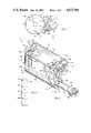
- FIG. 2is a perspective view on a much larger scale with parts broken away showing the ribbon cartridge in greater detail;
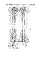
- FIG. 3is an exploded view in section on a still larger scale taken along line 3--3 of FIG. 2;
- FIG. 4is a scrap view on a small scale of the print ribbon in the FIG. 2 cartridge.
- color printing apparatusincludes a print head 10 which is positioned opposite a rotary drum 12. Located also opposite drum 12 adjacent to the head 10 is a print ribbon cartridge shown generally at 14 made in accordance with our invention.
- Cartridge 14is located properly relative to the print head 10 and drum 12 by placing it in a fitted receptacle or pocket 15a of the printing apparatus frame or base 15.
- Cartridge 14includes a print or thermal transfer ribbon 14a that extends into the gap between head 10 and the surface of drum 12.
- the length of ribbon 14ais composed of a repeating set of different color bands C, M and Y (FIG. 4) and a planar stretch of ribbon 14a opposite head 10 is exposed by the cartridge 14 to both the print head 10 and the drum surface.
- a recording mediumsuch as a sheet of paper S shown in dot-dash lines in FIG. 1 whose leading edge is secured to the drum 12 by a clip 16 incorporated into the drum 12.
- the head 10is moved between a "print” position in which the head 10 presses ribbon 14a and sheet S against the drum 12 and a "feed” position in which the head 10 is retracted from the drum 12 so that the ribbon 14a and drum 12 can be moved relative to the head 10.
- the printing apparatusis designed to print on a standard size sheet S, e.g. 81/2 ⁇ 11 inches. Therefore, the head 10 and drum 12 are at least 81/2 inches long and the drum 12 has a circumference in excess of 111/2 inches.
- the ribbon 14ais slightly less than 81/2 inches wide and its length may be as long as 3300 inches or even longer. This specific ribbon length accomodates 100 sets of three color bands Y, M, C, each such band being 11 inches long.
- the printing apparatusincludes a paper sheet feed path in the form of a guide 22 for guiding a paper sheet S shown in solid lines in FIG. 1 from a sheet feeder (not shown) in the direction of arrow 24 such that its leading edge is directed into clip 16 when the drum 12 is stopped by its drive means (not shown) at its so-called “release position” and the clip 16 is open as shown in solid lines in FIG. 1.
- the apparatusalso has a paper discharge path in the form of a second guide 26 positioned with one end adjacent clip 16, when the drum 12 is oriented as in FIG. 1, to receive the paper sheet S as it is ejected from clip 16 in the direction of arrow 28.
- the drive means of the apparatusis also arranged to stop the drum 12 in a "top-of-sheet" position in which the closed clip 16 is located adjacent to the print head 10 as indicated by the dot-dash lines in FIG. 1 so that the print head 10 is positioned to print the first line on the paper sheet S.
- drum 12is stopped at its release position and clip 16 is open as shown in solid lines in FIG. 1.
- clip 16With the clip 16 in that position, a paper sheet S can be fed along guide 22 in the direction of arrow 24 so that its leading edge is received in the gap 38 present between the clip 16 and the drum surface.
- clip 16is closed thereby clamping that edge to the drum 12 and drum 12 is rotated in the printing direction indicated by arrow 32 to its top-of-sheet position so that sheet S becomes wrapped around the drum 12 as indicated by the dot-dash lines in FIG. 1.
- the circumference of drum 12is related to the length of sheet S and the placement of guide 26 such that, when the drum 12 is in its top-of-sheet position, the trailing edge margin S' of sheet S rests on the paper guide 26 as shown in FIG. 1.
- the printing apparatusnow commences the first printing sequence.
- the printer controller(not shown) moves the print head 10 to its print position so that it presses print ribbon 14a and the sheet S against the surface of drum 12.
- the wires (not shown) of print head 10are energized selectively and the drum 12 is stepped around following the above-described print-and-feed sequence until all of the line positions on sheet S are printed with first color dots.
- the ribbon 14a in cartridge 14is advanced so that the first color band Y in the first set of bands Y, M, C on the ribbon 14a is moved past the head 10.
- head 10is moved to its retracted feed position while drum 12 continues rotating in the printing direction indicated by arrow 32 to its top-of-sheet position.
- ribbon cartridge 14is driven to advance the print ribbon 14a therein to bring the beginning of the second color band M opposite the print head wires.
- head 10is returned to its print position to commence printing the second color on sheet S, with the print ribbon 14a being advanced to move the second color band M of the first set past the head 10. This process is repeated until the sheet S has been printed with all of the colors present in the repeating set of bands Y, M, C on the print ribbon 14a.
- drum 12Upon completion of printing, drum 12 is rotated once again to its top-of-sheet position placing the tail end S' of the sheet S on guide 26 as shown in dotted lines in FIG. 1.
- Drum 12is now rotated in its release direction shown by arrow 34 in FIG. 1, causing the sheet S wrapped around the drum 12 to be pushed outward along the paper guide 26 in the direction of arrow 28.
- clip 16When the drum 12 reaches its release position shown in FIG. 1, clip 16 is opened as shown, thereby releasing the leading edge of the sheet S so that the sheet S is ejected along guide 26 to the exit end of the printing apparatus.
- cartridge 14comprises a casing or housing 42 composed of four molded plastic sections to be described presently which interfit to form a protective enclosure and a guide path for the print ribbon 14a. More particularly, casing 42 includes a feed tube section 44, a take-up tube section 46 and a pair of left and right end sections 48 and 52 respectively.
- Feed tube section 44is essentially an open ended tube having a lengthwise rectangular slot 54 which must be long enough to accommodate ribbon 14a.
- the illustrated cartridge 14has a slot 54 which is at least 81/2 inches long.
- Casing section 46includes a tubular portion 56 which is open at both ends and has a ribbon-receiving slot 58 which is more or less the same size as slot 54.
- Section 46also includes a blade portion 62 integral with tube portion 56. As the cartridge 14 is oriented in FIG. 2, portion 62 projects out laterally from tube portion 56 at the lower edge of slot 58. The blade portion 62 extends the entire length of section 46 and its outer edge margin is beveled and notched to form a sharp-edged turnbar 62a for turning the print ribbon 14a in its path of travel from slot 54 to slot 58.
- the turnbar 62ais slightly longer than the width of the ribbon 14a and prevents the advancing ribbon 14a from wandering laterally.
- Section 48is composed of a pair of similar annular bushings 64 and 66 which plug into the adjacent open ends of the feed tube section 44 and the tubular portion 56 of the take-up tube section 46. When that end section 48 is in place, the bushing flanges 64a and 66a are more or less flush with the outside walls of sections 44 and 46. As best seen in FIG.
- section 48also includes a strap 68 whose lower end, along with a reinforcing web 69, is an integral extension of bushing flange 64a and whose upper end is connected to bushing flange 66a by way of an integral web 72.
- Strap 68lies in a plane that is more or less perpendicular to the nominal plane of section 48 and its upper end has a notch 68a to provide clearance for the adjacent end of turnbar 62a.
- one or more small tabs 74project from the ends of sections 44 and 46, including the latter's blade portion 62, into registering slots 76 present in end section 48 seen in FIG. 2.
- Section 48is secured to sections 44 and 46 by a circular array of clips 78 formed integrally with bushing 64. These clips 78 extend into the end of section 44 and have noses or barbs 78a which snap into small slots 82 formed in the wall of section 44. Similar clips 84 extend from bushing 66 into tube portion 56 with the barbs 84a at the ends of those clips 84 engaging in appropriately placed slots 86 present in the wall of portion 56.
- a second circular array of integral clips 87project from bushing 64 parallel to clips 78 and a similar array of clips 88 project from bushing 66 parallel to clips 84.
- the clips 87, 88 in these arrayshave barbed ends 87a and 88a respectively which overhang their respective bushing passages 64b and 66b respectively. The purpose of these clips 87 and 88 will be described later.
- a pair of locating pins 89project straight out from casing end section 48 at diametrically opposite locations adjacent its bushing 66.
- these pins 89project into holes 15b in the end wall of the receptacle 15a to fix the position of the cartridge 14.
- a small finger or post 92whose function will be described later extends out in the same direction from section 48 at a location adjacent its bushing 64.
- the casing section 52 that connects the opposite ends of sections 44 and 46comprises a pair of similar annular bushings 102 and 104 having peripheral flanges 102a and 104a and central passages 102b and 104b respectively.
- the bushings 102 and 104are arranged to plug into the adjacent open ends of section 44 and tubular portion 56 of section 46 respectively.
- the bushings 102 and 104are joined by an integral planar web portion 106 which bridges the adjacent end of blade portion 62. Small tabs 108 project from the adjacent end of blade portion 62 into registering slots 109 in end portion 106 as best seen in FIG. 2.
- Section 52is permanently secured to sections 44 and 46 by applying an appropriate cement or bonding agent (not shown) to section 52 at the location of holes 109 and around the bushings 102 and 104. If desired, a similar cement may be applied to the appropriate surfaces of the opposite casing end section 48 in order to permanently bond that section to sections 44 and 46.
- the casing end section 52also is formed with an integral handle 110 to facilitate loading cartridge 14 into and withdrawing it from its receptacle 15a in the apparatus frame 15.
- the handle 110is essentially a generally rectangular loop or strap whose opposite ends connect to the end section web portion 106 at spaced-apart locations thereon between bushings 102 and 104.
- a latch 112is also formed as an integral part of the handle 110 which is a latch 112 for releasably locking cartridge 14 in its receptacle 15a.
- the latch 112is basically a resilient clip member 114 which branches at 114a from one end of handle 110, curves and extends through a clearance hole 115 provided in the web portion 106.
- the clip member 114is terminated by a barb 114b spaced a short distance from the opposite face of web portion 106.
- a tab 116extends laterally from the clip member 114 at a location thereon between its connection at 114a and web portion 106.
- the clip member 114resiliently flexes at its bridging connection 114a to handle 110 causing the barb 114 b of the clip member 114 to swing away from tubular portion 56 of the casing section 46.
- the barb 114b of the clip member 114engages behind a fram edge 15c as shown in FIG.
- the cartridge 14can be removed from the apparatus simply by disengaging the clip member 114 from frame edge 15c by depressing tab 116 while pulling on the cartridge handle 110.
- cartridge 14also includes a pair of tubular open-ended ribbon spools or cores 122 and 124 positioned inside casing section 44 and the tubular portion 56 of casing section 46 respectively.
- the ends of those cores 122 and 124 adjacent to the casing end section 48are rotatively mounted to that section's bushings 64 and 66 by a pair of identical generally cylindrical plug members 126.
- Each plug member 126is formed with a circumferential flange 128 which divides the member 126 lengthwise into inner and outer segments 132 and 134.
- Segment 132is relatively long with a generally cylindrical portion 132a adjacent flange 128, an intermediate slightly smaller diameter portion 132b and a tapered or frustoconical portion 132c.
- Plug member 126is dimensioned to fit somewhat snugly into the end of the associated ribbon core 122 or 124 so that the tube end seats on the shoulder 132d present between the plug segment portions 132a and 132b as shown in the lower half of FIG. 3.
- a pair of lengthwise tapered splines or keys 136are formed at diametrically opposite locations on plug segment portion 132b.
- the plug member segment 134 on the opposite side of flange 128is generally cylindrical with open ends and dimensioned to fit rotatively in the central passage 64b or 66b of the associated bushing 64 or 66.
- the plug member segment 134is rotatively locked to the associated bushing 64 or 66 by the above-mentioned clips 87 or 88 projecting from that bushing 64 or 66.
- the plug member 126As the plug member 126 is slid into the bushing passage 64b or 66b, its flange 128 deflects those clips 87 or 88 radially outward until the flange 128 seats on the circular edge of the bushing passage 64b whereupon the clip barbs 87a or 88a engage over the flange 128 as shown in the lower half of FIG. 3.
- the ribbon core 122is rotatively coupled to bushing 64 and core 124 is similarly coupled to bushing 66.
- the plug members 126can still be installed or assembled into the casing sections 44 and 46 simply by fitting them into the ends of their respective ribbon cores 122 and 124 and sliding the plug members 126 and cores 122 and 124 into the casing sections 44 and 46 through the bushing passages 102b and 104b in casing end section 52 until the plug members 126 are coupled to section 48 as described above.
- Each cap assembly 144comprises a generally cylindrical plug-like friction member 146 which is divided lengthwise by a circumferential flange 148 into inner and outer segments 152 and 154. Segment 152 is generally cylindrical and is arranged to plug tightly into the adjacent end of the associated ribbon core 122 or 124.
- a lengthwise key or spline 156extends along one side of segment 152 which engages in a notch 158 present in the end wall of the ribbon core 122 or 124 to rotatively couple the friction member 146 to the core 122 or 124.
- the other drag member segment 154is also more or less cylindrical. However, it is slotted lengthwise to form a circular array of resilient fingers 162.
- a relatively long cylindrical post 164extends axially from member segment 154 beyond the ends of fingers 162 and the free end 164a of that post 164 is knurled so that it can function as a stem for manually turning the friction member 146 and the ribbon core 122 or 124 coupled thereto.
- the friction member segment 154 of member 146is rotatively connected to a cap 166 which constitutes the remaining component of the cap assembly 144.
- Cap 166is composed of a flanged disk portion 168 whose flange diameter is slightly larger than the diameters of the openings 102b and 104b in the casing end section 52.
- Projecting endwise from the inner face of disk portion 168is a tubular portion 172 which is dimensioned to engage snugly around the friction member segment 154.
- a central opening 174is provided in disk portion 168 to provide clearance for post 164.
- the friction member 146can be rotated relative to the cap 166, say, by turning the stem 164a projecting from the cap 166.
- the engagements of the friction member's resilient fingers 162 against the wall of tube portion 172provide a certain amount of resistance to such rotation.
- Each cap 166has a pair of tabs 178 which extend out diametrically from the edge of its disk portion 168. These tabs 178 are arranged to key into diametrically placed notches 182 at the edge of the bushing passage 102b or 104b which that cap 166 is intended to close.
- the locking tabs 178are aligned with notches 182 so that the core 122 or 124 and cap assembly 144 can be slid into the casing 42 until the disk portion 168 of that assembly 144 seats in and closes the bushing passage 102b or 104b.
- a pair of ramps 188are formed on the inside surface of the casing end section 52 adjacent to notches 182 as shown in the lower half of FIG.
- a knobmay be frictionally engaged over each stem 164a to make it easier to turn the stem 164a and to hold the friction member segment 154 and its cap 166 together as an assembled unit.
- One such knobindicated in dot-dash lines at 190, is affixed to the upper stem 164a in FIG. 2.
- each cap assembly 144is released from the casing 42 by rotating its cap 166 in the unlocking, i.e. counterclockwise, direction.
- the ribbon core 122 or 124 coupled to itwill be retracted also because the core 122 or 124 fits more tightly to the cap assembly 144 than to the plug member 126 at the opposite end of the casing 42.
- the empty core 122 or 124can then be separated from the cap assembly 144 and replaced by a similar core or spool 122 or 124 having a length of print ribbon 14a wrapped about the core 122 or 124.
- This spooled ribbon 14awould normally be provided in a sealed package with a strip of adhesive tape 192 (FIG. 3) securing the outer leading edge of the ribbon 14a. Then the new ribbon 14a and cover assembly 144 are inserted into the cartridge casing section 44 and locked in place as described above and an empty core 122 is similarly positioned in the tubular portion 56 of the take-up section 46. Next, the user draws the leading end of the ribbon 14a with the adhesive strip 192 still attached out through the casing section slot 54. That slot 54 is made large enough so that the user can insert his fingers into section 44 to grasp the ribbon 14a.
- the ribbon 14ais draped over the turnbar 62a and threaded in through the other large casing slot 58 and attached to the empty core 124 present in the casing section 46 using the adhesive strip as shown at 192 in FIG. 3. Then, by turning the stems 164a at the end of casing 42, the leading end of the ribbon 14a can be wrapped to some extent around core 124 and the ribbon 14a made taut.
- section 44 and portion 56 of cartridge 14are juxtaposed so that their longitudinal axes are parallel and define a first plane.
- the turnbar 62ais spaced from that plane and its edge together with the proximal edge of slot 54 defines a second plane which intercepts the first plane making an acute angle therewith. Consequently, a large unobstructed stretch of ribbon 14a is present between the slot 54 and turnbar 62a which is accessible from behind to a long print head 10 positioned between casing section 44 and portion 56 of section 46.
- the ribbon 14aWhen loading fresh ribbon 14a into the cartridge casing 42 thusly, the ribbon 14a should be fed from and taken up on the sides of the cores 122 and 124 facing the sides of the casing 42 as shown in FIG. 2 so that a segment of the ribbon 14a is stretched properly between the inner edge of slot 58 and the edge of turnbar 62a.
- the proper orientation of each ribbon core 122 and 124is assured because only the core end containing the two slots 138 will engage properly on each plug member 126 projecting from the casing end section 48.
- Assembly 194includes a small electric gear motor 196 which is mounted to the printing apparatus frame 15 at the inner end of the cartridge receptacle 15a adjacent the locating holes 15b.
- the gear motor 196has an armature 196a which is rotatively coupled to a drive member 200 by way of a simple, low cost mechanical slip clutch 201 which includes a spring-loaded plate 201a and a clutch pad 201b.
- the diameter of the driver member 200is such that, when the cartridge 14 is seated in its receptacle 15a, the driver member 200 can be slidably received in the segment 134 of the plug member 126 coupled to the bushing 66 of cartridge end section 48.
- a pair of lengthwise slots 200aare formed at diameterically opposite locations on the driver member 200. These slots 200a are arranged to receive diametrically opposite lengthwise splines or keys 202 projecting from the inner surface of plug member 126 as shown in FIG. 3, so as to rotatively couple the driver member 200 to the plug member 126 as well as to the ribbon core 124 attached thereto.
- motor 196When motor 196 is energized, the core 124 is rotated to wind the ribbon 14a onto that core 124, thereby advancing the print ribbon 14a over the turnbar 62a in the direction indicated by the arrow 206 in FIG. 2.
- the slip clutch 201is an important feature of the invention. It permits the use of a single gear motor 196 in place of an expensive servo motor (not shown) and its ancillary control circuitry (not shown) as the means for advancing ribbon 14a even though the ribbon 14a moves at different speeds during the operation of the printer. More particularly, it is desirable to advance the ribbon 14a rapidly when positioning the ribbon 14a prior to printing each different color. During printing, on the other hand, when the ribbon 14a is being advanced line by line, the ribbon movement is much slower. In addition, assuming the ribbon take-up core 124 is rotated at constant speed, the surface speed of the ribbon 14a at the print station will vary directly with the radius of the ribbon roll or core 124.
- motor 196can be run at a selected constant speed that will position the ribbon 14a promptly prior to printing even when core 122 is almost empty of ribbon 14a.
- the print head 10is in its retracted position during this time so that the ribbon 14a is free to move rapidly.
- the clutch 201will slip, permitting the motor armature 196a to overrun the driver member 200 whenever the torque exerted on the driver member 200 becomes excessive due to such retardation or to ribbon 14a buildup on core 124. Consequently, the motor 196 is never overloaded due to the different ribbon speeds or even if the ribbon 14a is stopped because of a jam.
- a microswitch 208is mounted on the end wall of receptacle 15a with its actuator 208a located directly opposite the finger 92 described above that projects from the end of the loaded cartridge 14. The closing of that switch 208 provides an indication to the apparatus controller (not shown) that the cartridge 14 is seated properly and is ready to commence printing.
- the cartridge 14is removed from its receptacle in the printer by depressing the latch tab 116 and pulling on the cartridge handle 110. Then the cap assemblies 144 at the end of the casing 42 are unlocked and withdrawn, along with the cores 122 and 124, from the casing 42. The used ribbon 14a is discarded, saving the core 124 if desired. Then the now empty core 122 in the casing section 44 can be repositioned in section 46 to serve as the take-up core 124 for a new spooled ribbon 14a inserted into section 44 as described above.
- cartridge assembly 14all of the components of cartridge assembly 14 except the print ribbon 14a are reusable so that the cost of the cartridge 14 can be amortized over a long period of time. Finally, the cartridge 14 is returned to and locked in its receptacle 15a using the convenient handle 110 and latch 112 provided on the cartridge 14.
- the cartridge 14normally contains a print ribbon 14a for color printing composed of repeating sets of color bands or fields having the colors yellow (Y), magenta (M) and cyan (C), as shown in FIG. 4.
- a typical ribbon 14amay have one hundred or more repeats of the three color set YMC.
- the bandis preceded with a black index stripe or marking 212 as shown in FIG. 4.
- the stripe 212a preceding each color set, i.e. ahead of each yellow band,is made longer than the stripe 212 to define the beginning of each set.
- a pair of detectors 214 and 214aare mounted on the apparatus frame 15 so that, when the cartridge 14 is seated in that receptacle 15a, the detectors 214 and 214a are located opposite the exposed segment of ribbon 14a at the print station as shown in FIGS. 1 and 2 in position to detect the stripes 212 and 212a respectively.
- the detector 214aprovides an indication to the apparatus controller that the ribbon 14a is positioned at the beginning of a three-color set and is thus ready to commence printing on a sheet S.
- the detection by detector 214 of a stripe 212 or 212aindicates to the controller that the ribbon 14a is positioned to print each successive color within a color set.
- the stripes 212 and 212aprovide initialization information at the beginning of a printing cycle as well as ribbon position information with respect to each of the color bands Y, M, C on the ribbon 14a within a given cycle while printing the different colors on sheet S.
- the detectors 214 and 214acan even be arranged to identify the particular color band Y, M or C present or moving into the print station of the apparatus.
- the controllercan then position the ribbon 14a selectively so that, as each color band is required, it is moved into the print station.
- the cartridge 14greatly facilitates the handling of print ribbons 14a and especially the large thermal transfer ribbons 14a customarily used in thermal printers.
- the cartridge 14is very user friendly in that it can be inserted into and removed from its receptacle 15a in the printing apparatus quite easily using the handle 110 and integral latch 112.
- the ribbon 14a in the cartridge 14is properly positioned prior to printing each different color on sheet S as well as during printing by a simple inexpensive gear motor assembly 194 instead of by a servo drive as is commonly done in conventional printers of this type, with the proper position of the ribbon 14a being assured by the detection of the position stripes 212 and 212a present on the ribbon 14a.
- the usercan remove the cartridge 14 from the printing apparatus and replace the ribbon 14a with a fresh one so that the same cartridge 14 can be used again and again.
- the construction of the cartridge 14 described aboveenables the user to remove the ribbon cores 122 and 124 from the cartridge casing 42, insert a fresh ribbon 14a into the casing 42 and reuse the empty core 124 as the take-up core 124 for the new ribbon 14a with minimum effort. Therefore, the present cartridge 14 should find wide application, particularly in thermal printers of the type requiring unusually large print ribbons 14a to print in color on successive sheets S of paper.
Landscapes
- Impression-Transfer Materials And Handling Thereof (AREA)
Abstract
Description
Claims (25)
Priority Applications (1)
| Application Number | Priority Date | Filing Date | Title |
|---|---|---|---|
| US06/765,077US4673304A (en) | 1985-08-13 | 1985-08-13 | Thermal printer ribbon cartridge for wide ribbons |
Applications Claiming Priority (1)
| Application Number | Priority Date | Filing Date | Title |
|---|---|---|---|
| US06/765,077US4673304A (en) | 1985-08-13 | 1985-08-13 | Thermal printer ribbon cartridge for wide ribbons |
Publications (1)
| Publication Number | Publication Date |
|---|---|
| US4673304Atrue US4673304A (en) | 1987-06-16 |
Family
ID=25072577
Family Applications (1)
| Application Number | Title | Priority Date | Filing Date |
|---|---|---|---|
| US06/765,077Expired - Fee RelatedUS4673304A (en) | 1985-08-13 | 1985-08-13 | Thermal printer ribbon cartridge for wide ribbons |
Country Status (1)
| Country | Link |
|---|---|
| US (1) | US4673304A (en) |
Cited By (52)
| Publication number | Priority date | Publication date | Assignee | Title |
|---|---|---|---|---|
| US4836697A (en)* | 1988-03-21 | 1989-06-06 | Kroy Inc. | Automated thermal transfer device and control system therefor |
| US4915516A (en)* | 1987-07-24 | 1990-04-10 | Hitachi, Ltd. | Thermal transfer recording apparatus with ink paper cassette |
| US4930911A (en)* | 1986-04-24 | 1990-06-05 | Taurus Impressions, Inc. | Flat-bed heated finger daisy wheel hot debossing stamper |
| US4944621A (en)* | 1988-12-22 | 1990-07-31 | Burdick Corporation | Self-contained printhead/paperdrive mechanism |
| US4944619A (en)* | 1987-06-08 | 1990-07-31 | Star Seimitsu Kabushiki Kaisha | Construction for mounting an ink ribbon cassette in a heat transferable line printer |
| EP0387699A1 (en)* | 1989-03-13 | 1990-09-19 | LEPTONS ITALIA S.p.A. | Cartridge of heat-sensitive material for thermal printers |
| US4997298A (en)* | 1989-03-08 | 1991-03-05 | Tokyo Electric Co., Ltd. | Method and apparatus for loading ink ribbon |
| US5009531A (en)* | 1989-01-20 | 1991-04-23 | Tokyo Electric Co., Ltd. | Color ink ribbon and printer using this ribbon |
| US5011310A (en)* | 1988-08-26 | 1991-04-30 | Siemens Aktiengesellschaft | Inked ribbon cartridge with removable carrier member |
| US5078523A (en)* | 1988-03-04 | 1992-01-07 | Varitronic Systems, Inc. | Tape cassette with identifying circuit element for printing machine |
| US5085529A (en)* | 1988-10-17 | 1992-02-04 | Insignia Systems, Inc. | Thermal printing system with encoded sheet set |
| US5160205A (en)* | 1991-06-17 | 1992-11-03 | Monarch Marking Systems, Inc. | Thermal printer with adjustable ink ribbon guide roll |
| US5174667A (en)* | 1990-03-30 | 1992-12-29 | Tokyo Electric Co., Ltd. | Transfer printer |
| US5186553A (en)* | 1986-07-15 | 1993-02-16 | Monarch Marking Systems, Inc. | Printer and method |
| US5238314A (en)* | 1990-07-13 | 1993-08-24 | Tokyo Electric Co., Ltd. | Transfer printer with ribbon lock |
| US5246298A (en)* | 1986-07-15 | 1993-09-21 | Monarch Marking Systems, Inc. | Ink ribbon cartridge and installation methods relating thereto |
| EP0515224A3 (en)* | 1991-05-24 | 1993-09-29 | Mitsubishi Denki Kabushiki Kaisha | Paper feed for printing apparatus |
| US5318370A (en)* | 1992-11-17 | 1994-06-07 | Varitronic Systems, Inc. | Cartridge with data memory system and method regarding same |
| US5352048A (en)* | 1988-12-23 | 1994-10-04 | Canon Kabushiki Kaisha | Ink sheet cassette and recording apparatus capable of loading the ink sheet cassette |
| US5366307A (en)* | 1988-10-17 | 1994-11-22 | Mcgourty Thomas K | Printing control system and method for scalably controlling print energy and cycle time |
| DE4332608A1 (en)* | 1993-09-24 | 1995-03-30 | Esselte Meto Int Gmbh | cassette |
| EP0666181A1 (en)* | 1994-02-02 | 1995-08-09 | Casio Computer Co., Ltd. | Ribbon cassette from which a supply reel or a take-up reel can be pulled out, and a thermal transfer printing apparatus using the ribbon cassette |
| EP0705708A2 (en) | 1994-10-05 | 1996-04-10 | Monarch Marking Systems, Inc. | Ink ribbon cartridge |
| US5588756A (en)* | 1993-10-15 | 1996-12-31 | Monarch Marking Systems, Inc. | Ink ribbon cartridge and method of installing same |
| US5752777A (en)* | 1992-10-06 | 1998-05-19 | Seiko Epson Corporation | Tape printing device and tape cartridge used therein |
| US5795083A (en)* | 1994-01-20 | 1998-08-18 | Imperial Chemical Industries Plc | Thermal transfer ribbon cassette |
| WO1999020471A3 (en)* | 1997-10-22 | 1999-07-01 | Ici Plc | Dyesheet cassette and printing apparatus |
| US5921687A (en)* | 1991-05-24 | 1999-07-13 | Mitsubishi Denki Kabushiki Kaisha | Printing apparatus |
| US6276849B1 (en)* | 1999-07-08 | 2001-08-21 | Brady Worldwide, Inc. | Printer spool and spool drive cone having radially extending teeth |
| US6307581B1 (en) | 1997-11-18 | 2001-10-23 | Matsushita Graphic Communication Systems, Inc. | Ink film unit and facsimile apparatus |
| US20020024583A1 (en)* | 2000-03-31 | 2002-02-28 | Brother Kogyo Kabushiki Kaisha | Ink sheet cartridge and exchangeable ink-sheet set mounted on the ink sheet cartridge |
| US6623192B1 (en) | 1998-01-06 | 2003-09-23 | Brother Kogyo Kabushiki Kaisha | Ink ribbon cartridge having protrusion and recessed portion |
| US6666597B1 (en)* | 2001-10-31 | 2003-12-23 | International Imaging Materials Inc. | Geared drive hub assembly for a printer cartridge |
| US6715946B2 (en) | 1998-01-06 | 2004-04-06 | Brother Kogyo Kabushiki Kaisha | Ink ribbon cartridge and printing device |
| US20040109715A1 (en)* | 1999-01-25 | 2004-06-10 | Fargo Electronics, Inc. | Identification card printer and ribbon cartridge |
| US20040114981A1 (en)* | 1999-01-25 | 2004-06-17 | Fargo Electronics, Inc. | Identification card printer ribbon cartridge |
| US20040237822A1 (en)* | 2003-05-30 | 2004-12-02 | Clemson University | Ink-jet printing of viable cells |
| US20050129444A1 (en)* | 1998-01-06 | 2005-06-16 | Brother Kogyo Kabushiki Kaisha | Ink ribbon cartridge |
| US20060071420A1 (en)* | 2003-08-19 | 2006-04-06 | Meier James R | Credential substrate rotator and processing module |
| US20080216688A1 (en)* | 2007-03-08 | 2008-09-11 | Fargo Electronics, Inc. | Inverted Reverse-Image Transfer Printing |
| US8192098B1 (en) | 2008-06-17 | 2012-06-05 | Stalsen LLC | Automatically loading printing device and method of printing |
| US8556205B2 (en) | 2011-01-28 | 2013-10-15 | Eastman Kodak Company | Printer web medium supply |
| US8646770B2 (en) | 2009-09-18 | 2014-02-11 | Hid Global Corporation | Card substrate rotator with lift mechanism |
| US8703216B2 (en) | 2011-07-26 | 2014-04-22 | The Curators Of The University Of Missouri | Engineered comestible meat |
| US8740131B2 (en) | 2011-01-28 | 2014-06-03 | Eastman Kodak Company | Printer web medium supply with drive system |
| US8910900B2 (en) | 2011-01-28 | 2014-12-16 | Eastman Kodak Company | Method for operating printer web medium supply |
| US9332779B2 (en) | 2014-02-05 | 2016-05-10 | Modern Meadow, Inc. | Dried food products formed from cultured muscle cells |
| US9752122B2 (en) | 2013-09-13 | 2017-09-05 | Modern Meadow, Inc. | Edible and animal-product-free microcarriers for engineered meat |
| US11001679B2 (en) | 2016-02-15 | 2021-05-11 | Modern Meadow, Inc. | Biofabricated material containing collagen fibrils |
| US11214844B2 (en) | 2017-11-13 | 2022-01-04 | Modern Meadow, Inc. | Biofabricated leather articles having zonal properties |
| US11352497B2 (en) | 2019-01-17 | 2022-06-07 | Modern Meadow, Inc. | Layered collagen materials and methods of making the same |
| US11913166B2 (en) | 2015-09-21 | 2024-02-27 | Modern Meadow, Inc. | Fiber reinforced tissue composites |
Citations (29)
| Publication number | Priority date | Publication date | Assignee | Title |
|---|---|---|---|---|
| US797888A (en)* | 1904-12-13 | 1905-08-22 | Wilbur I Follett | Ribbon-holder for time and other stamps. |
| DE386405C (en)* | 1921-04-03 | 1923-12-18 | Archo Schreibmaschinen Company | Device for fastening the ribbon reels of typewriters |
| US3026987A (en)* | 1958-11-27 | 1962-03-27 | Gather Rudolf | Ribbon feeding device for typewriting machine |
| US3393790A (en)* | 1966-07-29 | 1968-07-23 | Columbia Ribbon & Carbon | Ribbon spools |
| US3400800A (en)* | 1965-08-16 | 1968-09-10 | Data Products Corp | Printing ribbon support apparatus including ribbon guide means |
| US3774538A (en)* | 1970-11-27 | 1973-11-27 | Polaroid Corp | Ink web cassette for rotary printing system |
| US3807543A (en)* | 1971-09-27 | 1974-04-30 | Smc Corp | Ribbon spool spindle |
| US3855926A (en)* | 1973-08-06 | 1974-12-24 | J Dikoff | Signature writer |
| US3923267A (en)* | 1974-06-03 | 1975-12-02 | Honeywell Inf Systems | Ribbon feed mechanism for feeding type ribbon on type ribbon spools |
| US3952649A (en)* | 1974-04-25 | 1976-04-27 | Dikoff Joseph K | Check printer having ribbon cartridge |
| US3954167A (en)* | 1974-10-17 | 1976-05-04 | Extel Corporation | High speed printer |
| US3991676A (en)* | 1973-05-14 | 1976-11-16 | Oki Electric Industry Company, Ltd. | High speed printer with multicolor ink ribbon |
| US4160605A (en)* | 1977-09-26 | 1979-07-10 | Pitney Bowes Deutschland Gmbh | Ink ribbon box |
| JPS5667278A (en)* | 1979-11-06 | 1981-06-06 | Fujitsu Ltd | Heat transferring recording device |
| US4289069A (en)* | 1979-04-18 | 1981-09-15 | Trilog, Inc. | Method for producing a multiple color hard copy image |
| JPS5824478A (en)* | 1981-08-06 | 1983-02-14 | Fujitsu Ltd | Recorder |
| US4388628A (en)* | 1980-09-01 | 1983-06-14 | Fuji Xerox Co., Ltd. | Multi-color thermal transfer recorder |
| US4401390A (en)* | 1979-04-18 | 1983-08-30 | Trilog, Inc. | Ribbon control system for multiple color impact printer |
| JPS58173687A (en)* | 1982-04-06 | 1983-10-12 | Fuji Xerox Co Ltd | Transfer type heat sensitive recording apparatus |
| JPS58193184A (en)* | 1982-05-07 | 1983-11-10 | Seiko Instr & Electronics Ltd | Thermosensitive color transfer apparatus |
| US4496955A (en)* | 1981-06-05 | 1985-01-29 | Sony Corporation | Apparatus for thermal printing |
| DE3425953A1 (en)* | 1983-07-15 | 1985-01-31 | Kabushiki Kaisha Toshiba, Kawasaki, Kanagawa | PRINTING DEVICE |
| US4502057A (en)* | 1982-08-30 | 1985-02-26 | Shinko Electric Co., Ltd. | Method and apparatus for detecting errors in an ink ribbon in a thermal transfer type multicolor printer |
| US4505603A (en)* | 1982-02-16 | 1985-03-19 | Tokyo Shibaura Denki Kabushiki Kaisha | Thermal transfer color printer and a method relating thereto |
| US4534666A (en)* | 1983-06-13 | 1985-08-13 | Kabushiki Kaisha Toshiba | Transfer material feeding device |
| US4551729A (en)* | 1982-07-09 | 1985-11-05 | Shinko Electric Co., Ltd. | Method of making thermal transfer type multicolor printing |
| US4552470A (en)* | 1982-11-24 | 1985-11-12 | Tokyo Shibaura Denki Kabushiki Kaisha | Thermal transfer color printer for printing on sheets of paper |
| US4558329A (en)* | 1982-09-09 | 1985-12-10 | Sony Corporation | Ink carrier ribbon for sublimation transfer |
| US4594597A (en)* | 1985-08-13 | 1986-06-10 | Sanders Associates, Inc. | Thermal printer |
- 1985
- 1985-08-13USUS06/765,077patent/US4673304A/ennot_activeExpired - Fee Related
Patent Citations (29)
| Publication number | Priority date | Publication date | Assignee | Title |
|---|---|---|---|---|
| US797888A (en)* | 1904-12-13 | 1905-08-22 | Wilbur I Follett | Ribbon-holder for time and other stamps. |
| DE386405C (en)* | 1921-04-03 | 1923-12-18 | Archo Schreibmaschinen Company | Device for fastening the ribbon reels of typewriters |
| US3026987A (en)* | 1958-11-27 | 1962-03-27 | Gather Rudolf | Ribbon feeding device for typewriting machine |
| US3400800A (en)* | 1965-08-16 | 1968-09-10 | Data Products Corp | Printing ribbon support apparatus including ribbon guide means |
| US3393790A (en)* | 1966-07-29 | 1968-07-23 | Columbia Ribbon & Carbon | Ribbon spools |
| US3774538A (en)* | 1970-11-27 | 1973-11-27 | Polaroid Corp | Ink web cassette for rotary printing system |
| US3807543A (en)* | 1971-09-27 | 1974-04-30 | Smc Corp | Ribbon spool spindle |
| US3991676A (en)* | 1973-05-14 | 1976-11-16 | Oki Electric Industry Company, Ltd. | High speed printer with multicolor ink ribbon |
| US3855926A (en)* | 1973-08-06 | 1974-12-24 | J Dikoff | Signature writer |
| US3952649A (en)* | 1974-04-25 | 1976-04-27 | Dikoff Joseph K | Check printer having ribbon cartridge |
| US3923267A (en)* | 1974-06-03 | 1975-12-02 | Honeywell Inf Systems | Ribbon feed mechanism for feeding type ribbon on type ribbon spools |
| US3954167A (en)* | 1974-10-17 | 1976-05-04 | Extel Corporation | High speed printer |
| US4160605A (en)* | 1977-09-26 | 1979-07-10 | Pitney Bowes Deutschland Gmbh | Ink ribbon box |
| US4289069A (en)* | 1979-04-18 | 1981-09-15 | Trilog, Inc. | Method for producing a multiple color hard copy image |
| US4401390A (en)* | 1979-04-18 | 1983-08-30 | Trilog, Inc. | Ribbon control system for multiple color impact printer |
| JPS5667278A (en)* | 1979-11-06 | 1981-06-06 | Fujitsu Ltd | Heat transferring recording device |
| US4388628A (en)* | 1980-09-01 | 1983-06-14 | Fuji Xerox Co., Ltd. | Multi-color thermal transfer recorder |
| US4496955A (en)* | 1981-06-05 | 1985-01-29 | Sony Corporation | Apparatus for thermal printing |
| JPS5824478A (en)* | 1981-08-06 | 1983-02-14 | Fujitsu Ltd | Recorder |
| US4505603A (en)* | 1982-02-16 | 1985-03-19 | Tokyo Shibaura Denki Kabushiki Kaisha | Thermal transfer color printer and a method relating thereto |
| JPS58173687A (en)* | 1982-04-06 | 1983-10-12 | Fuji Xerox Co Ltd | Transfer type heat sensitive recording apparatus |
| JPS58193184A (en)* | 1982-05-07 | 1983-11-10 | Seiko Instr & Electronics Ltd | Thermosensitive color transfer apparatus |
| US4551729A (en)* | 1982-07-09 | 1985-11-05 | Shinko Electric Co., Ltd. | Method of making thermal transfer type multicolor printing |
| US4502057A (en)* | 1982-08-30 | 1985-02-26 | Shinko Electric Co., Ltd. | Method and apparatus for detecting errors in an ink ribbon in a thermal transfer type multicolor printer |
| US4558329A (en)* | 1982-09-09 | 1985-12-10 | Sony Corporation | Ink carrier ribbon for sublimation transfer |
| US4552470A (en)* | 1982-11-24 | 1985-11-12 | Tokyo Shibaura Denki Kabushiki Kaisha | Thermal transfer color printer for printing on sheets of paper |
| US4534666A (en)* | 1983-06-13 | 1985-08-13 | Kabushiki Kaisha Toshiba | Transfer material feeding device |
| DE3425953A1 (en)* | 1983-07-15 | 1985-01-31 | Kabushiki Kaisha Toshiba, Kawasaki, Kanagawa | PRINTING DEVICE |
| US4594597A (en)* | 1985-08-13 | 1986-06-10 | Sanders Associates, Inc. | Thermal printer |
Cited By (93)
| Publication number | Priority date | Publication date | Assignee | Title |
|---|---|---|---|---|
| US4930911A (en)* | 1986-04-24 | 1990-06-05 | Taurus Impressions, Inc. | Flat-bed heated finger daisy wheel hot debossing stamper |
| US5246298A (en)* | 1986-07-15 | 1993-09-21 | Monarch Marking Systems, Inc. | Ink ribbon cartridge and installation methods relating thereto |
| US5186553A (en)* | 1986-07-15 | 1993-02-16 | Monarch Marking Systems, Inc. | Printer and method |
| US4944619A (en)* | 1987-06-08 | 1990-07-31 | Star Seimitsu Kabushiki Kaisha | Construction for mounting an ink ribbon cassette in a heat transferable line printer |
| US4915516A (en)* | 1987-07-24 | 1990-04-10 | Hitachi, Ltd. | Thermal transfer recording apparatus with ink paper cassette |
| USRE34521E (en)* | 1987-07-24 | 1994-01-25 | Hitachi, Ltd. | Thermal transfer recording apparatus with ink paper cassette |
| US5078523A (en)* | 1988-03-04 | 1992-01-07 | Varitronic Systems, Inc. | Tape cassette with identifying circuit element for printing machine |
| US4836697A (en)* | 1988-03-21 | 1989-06-06 | Kroy Inc. | Automated thermal transfer device and control system therefor |
| US5011310A (en)* | 1988-08-26 | 1991-04-30 | Siemens Aktiengesellschaft | Inked ribbon cartridge with removable carrier member |
| US5085529A (en)* | 1988-10-17 | 1992-02-04 | Insignia Systems, Inc. | Thermal printing system with encoded sheet set |
| US5366307A (en)* | 1988-10-17 | 1994-11-22 | Mcgourty Thomas K | Printing control system and method for scalably controlling print energy and cycle time |
| US4944621A (en)* | 1988-12-22 | 1990-07-31 | Burdick Corporation | Self-contained printhead/paperdrive mechanism |
| US5352048A (en)* | 1988-12-23 | 1994-10-04 | Canon Kabushiki Kaisha | Ink sheet cassette and recording apparatus capable of loading the ink sheet cassette |
| US5009531A (en)* | 1989-01-20 | 1991-04-23 | Tokyo Electric Co., Ltd. | Color ink ribbon and printer using this ribbon |
| EP0386982A3 (en)* | 1989-03-08 | 1991-08-14 | Tokyo Electric Co., Ltd. | Method and apparatus for loading ink ribbon |
| US4997298A (en)* | 1989-03-08 | 1991-03-05 | Tokyo Electric Co., Ltd. | Method and apparatus for loading ink ribbon |
| USRE34629E (en)* | 1989-03-08 | 1994-06-07 | Tokyo Electric Co., Ltd. | Method and apparatus for loading ink ribbon |
| EP0387699A1 (en)* | 1989-03-13 | 1990-09-19 | LEPTONS ITALIA S.p.A. | Cartridge of heat-sensitive material for thermal printers |
| EP0654358A3 (en)* | 1990-03-30 | 1997-03-19 | Tokyo Electric Co Ltd | Transfer printer. |
| US5174667A (en)* | 1990-03-30 | 1992-12-29 | Tokyo Electric Co., Ltd. | Transfer printer |
| US5238314A (en)* | 1990-07-13 | 1993-08-24 | Tokyo Electric Co., Ltd. | Transfer printer with ribbon lock |
| EP0515224A3 (en)* | 1991-05-24 | 1993-09-29 | Mitsubishi Denki Kabushiki Kaisha | Paper feed for printing apparatus |
| US5921687A (en)* | 1991-05-24 | 1999-07-13 | Mitsubishi Denki Kabushiki Kaisha | Printing apparatus |
| US5474394A (en)* | 1991-05-24 | 1995-12-12 | Mitsubishi Denki Kabushiki Kaisha | Printing apparatus |
| US5160205A (en)* | 1991-06-17 | 1992-11-03 | Monarch Marking Systems, Inc. | Thermal printer with adjustable ink ribbon guide roll |
| US5752777A (en)* | 1992-10-06 | 1998-05-19 | Seiko Epson Corporation | Tape printing device and tape cartridge used therein |
| US5967678A (en)* | 1992-10-06 | 1999-10-19 | Seiko Epson Corp. | Tape printing device and tape cartridge used therein |
| US5765954A (en)* | 1992-10-06 | 1998-06-16 | Seiko Epson Corporation | Tape printing device and tape cartridge used therein |
| US5887993A (en)* | 1992-10-06 | 1999-03-30 | Seiko Epson Corporation | Tape printing device and tape cartridge used therein |
| US5318370A (en)* | 1992-11-17 | 1994-06-07 | Varitronic Systems, Inc. | Cartridge with data memory system and method regarding same |
| US5553952A (en)* | 1993-09-24 | 1996-09-10 | Esselte Meto International Gmbh | Reusable ink ribbon cassette for a label printer, the cassette being capable of accommodating ink ribbons having different widths |
| EP0645258A3 (en)* | 1993-09-24 | 1997-11-26 | ESSELTE METO INTERNATIONAL GmbH | Printing machine |
| EP0960742A1 (en)* | 1993-09-24 | 1999-12-01 | Esselte Meto International GmbH | Printing machine |
| DE4332608C2 (en)* | 1993-09-24 | 2003-01-09 | Meto International Gmbh | cassette |
| DE4332608A1 (en)* | 1993-09-24 | 1995-03-30 | Esselte Meto Int Gmbh | cassette |
| US6412996B1 (en) | 1993-10-15 | 2002-07-02 | Monarch Marking Systems, Inc. | Ink ribbon cartridge |
| US6386775B1 (en) | 1993-10-15 | 2002-05-14 | Monarch Marking Systems, Inc. | Printer and method |
| US6533476B2 (en) | 1993-10-15 | 2003-03-18 | Monarch Marking Systems, Inc. | Printer and methods |
| US5785442A (en)* | 1993-10-15 | 1998-07-28 | Monarch Marking Systems, Inc. | Printer housing structure |
| US5938351A (en)* | 1993-10-15 | 1999-08-17 | Monarch Marking Systems, Inc. | Ink ribbon cartridge with ribbon tensioning structure |
| US5772341A (en)* | 1993-10-15 | 1998-06-30 | Monarch Marking Systems, Inc. | Ink ribbon cartridge |
| US5588756A (en)* | 1993-10-15 | 1996-12-31 | Monarch Marking Systems, Inc. | Ink ribbon cartridge and method of installing same |
| US5795083A (en)* | 1994-01-20 | 1998-08-18 | Imperial Chemical Industries Plc | Thermal transfer ribbon cassette |
| EP0666181A1 (en)* | 1994-02-02 | 1995-08-09 | Casio Computer Co., Ltd. | Ribbon cassette from which a supply reel or a take-up reel can be pulled out, and a thermal transfer printing apparatus using the ribbon cassette |
| EP0705708A2 (en) | 1994-10-05 | 1996-04-10 | Monarch Marking Systems, Inc. | Ink ribbon cartridge |
| WO1999020471A3 (en)* | 1997-10-22 | 1999-07-01 | Ici Plc | Dyesheet cassette and printing apparatus |
| CN1117470C (en)* | 1997-11-18 | 2003-08-06 | 松下电送系统株式会社 | Ink film unit and facsimile apparatus |
| US6307581B1 (en) | 1997-11-18 | 2001-10-23 | Matsushita Graphic Communication Systems, Inc. | Ink film unit and facsimile apparatus |
| US20050129444A1 (en)* | 1998-01-06 | 2005-06-16 | Brother Kogyo Kabushiki Kaisha | Ink ribbon cartridge |
| US6623192B1 (en) | 1998-01-06 | 2003-09-23 | Brother Kogyo Kabushiki Kaisha | Ink ribbon cartridge having protrusion and recessed portion |
| US6991388B2 (en) | 1998-01-06 | 2006-01-31 | Brother Kogyo Kabushiki Kaisha | Ink ribbon cartridge having takeup-side cover with opening positioned beneath protrusion in cover |
| US6715946B2 (en) | 1998-01-06 | 2004-04-06 | Brother Kogyo Kabushiki Kaisha | Ink ribbon cartridge and printing device |
| US7344325B2 (en) | 1999-01-25 | 2008-03-18 | Fargo Electronics, Inc. | Identification card printer having ribbon cartridge with cleaner roller |
| US7018117B2 (en)* | 1999-01-25 | 2006-03-28 | Fargo Electronics, Inc. | Identification card printer ribbon cartridge |
| US20040109715A1 (en)* | 1999-01-25 | 2004-06-10 | Fargo Electronics, Inc. | Identification card printer and ribbon cartridge |
| US20040114981A1 (en)* | 1999-01-25 | 2004-06-17 | Fargo Electronics, Inc. | Identification card printer ribbon cartridge |
| US6276849B1 (en)* | 1999-07-08 | 2001-08-21 | Brady Worldwide, Inc. | Printer spool and spool drive cone having radially extending teeth |
| US20020024583A1 (en)* | 2000-03-31 | 2002-02-28 | Brother Kogyo Kabushiki Kaisha | Ink sheet cartridge and exchangeable ink-sheet set mounted on the ink sheet cartridge |
| US7758263B2 (en) | 2000-03-31 | 2010-07-20 | Brother Kogyo Kabushiki Kaisha | Ink ribbon cartridge having projections extending from connecting members |
| US6827510B2 (en) | 2000-03-31 | 2004-12-07 | Brother Kogyo Kabushiki Kaisha | Ink sheet cartridge having partitioning plate including at least two symmetrically positioned recesses |
| US20050063755A1 (en)* | 2000-03-31 | 2005-03-24 | Brother Kogyo Kabushiki Kaisha | Image forming device and ink sheet cartridge mounted on the image forming device |
| US20040136766A1 (en)* | 2000-03-31 | 2004-07-15 | Brother Kogyo Kabushiki Kaisha | Ink sheet cartridge and exchangeable ink-sheet set mounted on the ink sheet cartridge |
| US6621510B2 (en) | 2000-03-31 | 2003-09-16 | Brother Kogyo Kabushiki Kaisha | Ink sheet cartridge and exchangeable ink-sheet set mounted on the ink sheet cartridge |
| US20080181705A1 (en)* | 2000-03-31 | 2008-07-31 | Brother Kogyo Kabushiki Kaisha | Image forming device and ink sheet cartridge mounted on the image forming device |
| EP1182043A3 (en)* | 2000-03-31 | 2002-04-03 | Brother Kogyo Kabushiki Kaisha | Ink sheet cartridge and exchangeable ink-sheet set mounted on the ink sheet cartridge |
| US7079167B2 (en) | 2000-03-31 | 2006-07-18 | Brother Kogyo Kabushiki Kaisha | Ink sheet cartridge and exchangeable ink-sheet set mounted on the ink sheet cartridge |
| US7102659B2 (en) | 2000-03-31 | 2006-09-05 | Brother Kogyo Kabushiki Kaisha | Ink sheet cartridge and exchangeable ink-sheet set mounted on the ink sheet cartridge |
| US7367727B2 (en) | 2000-03-31 | 2008-05-06 | Brother Kogyo Kabushiki Kaisha | Ink sheet cartridge having paper guide |
| US6666597B1 (en)* | 2001-10-31 | 2003-12-23 | International Imaging Materials Inc. | Geared drive hub assembly for a printer cartridge |
| US20060204308A1 (en)* | 2003-04-02 | 2006-09-14 | Fargo Electronics, Inc. | Identification card printer ribbon cartridge |
| US7051654B2 (en) | 2003-05-30 | 2006-05-30 | Clemson University | Ink-jet printing of viable cells |
| US20040237822A1 (en)* | 2003-05-30 | 2004-12-02 | Clemson University | Ink-jet printing of viable cells |
| US7878505B2 (en) | 2003-08-19 | 2011-02-01 | Hid Global Corporation | Credential substrate rotator and processing module |
| US20060071420A1 (en)* | 2003-08-19 | 2006-04-06 | Meier James R | Credential substrate rotator and processing module |
| US8834046B2 (en) | 2007-03-08 | 2014-09-16 | Assa Abloy Ab | Inverted reverse-image transfer printing |
| US20080216688A1 (en)* | 2007-03-08 | 2008-09-11 | Fargo Electronics, Inc. | Inverted Reverse-Image Transfer Printing |
| US8192098B1 (en) | 2008-06-17 | 2012-06-05 | Stalsen LLC | Automatically loading printing device and method of printing |
| US8646770B2 (en) | 2009-09-18 | 2014-02-11 | Hid Global Corporation | Card substrate rotator with lift mechanism |
| US8910900B2 (en) | 2011-01-28 | 2014-12-16 | Eastman Kodak Company | Method for operating printer web medium supply |
| US8740131B2 (en) | 2011-01-28 | 2014-06-03 | Eastman Kodak Company | Printer web medium supply with drive system |
| US8556205B2 (en) | 2011-01-28 | 2013-10-15 | Eastman Kodak Company | Printer web medium supply |
| US8703216B2 (en) | 2011-07-26 | 2014-04-22 | The Curators Of The University Of Missouri | Engineered comestible meat |
| US11707077B2 (en) | 2011-07-26 | 2023-07-25 | The Curators Of The University Of Missouri | Engineered comestible meat |
| US9752122B2 (en) | 2013-09-13 | 2017-09-05 | Modern Meadow, Inc. | Edible and animal-product-free microcarriers for engineered meat |
| US9332779B2 (en) | 2014-02-05 | 2016-05-10 | Modern Meadow, Inc. | Dried food products formed from cultured muscle cells |
| US11913166B2 (en) | 2015-09-21 | 2024-02-27 | Modern Meadow, Inc. | Fiber reinforced tissue composites |
| US11525042B2 (en) | 2016-02-15 | 2022-12-13 | Modern Meadow, Inc. | Composite biofabricated material |
| US11286354B2 (en) | 2016-02-15 | 2022-03-29 | Modern Meadow, Inc. | Method for making a biofabricated material containing collagen fibrils |
| US11530304B2 (en) | 2016-02-15 | 2022-12-20 | Modern Meadow, Inc. | Biofabricated material containing collagen fibrils |
| US11542374B2 (en) | 2016-02-15 | 2023-01-03 | Modern Meadow, Inc. | Composite biofabricated material |
| US11001679B2 (en) | 2016-02-15 | 2021-05-11 | Modern Meadow, Inc. | Biofabricated material containing collagen fibrils |
| US11214844B2 (en) | 2017-11-13 | 2022-01-04 | Modern Meadow, Inc. | Biofabricated leather articles having zonal properties |
| US11352497B2 (en) | 2019-01-17 | 2022-06-07 | Modern Meadow, Inc. | Layered collagen materials and methods of making the same |
Similar Documents
| Publication | Publication Date | Title |
|---|---|---|
| US4673304A (en) | Thermal printer ribbon cartridge for wide ribbons | |
| EP1504916B1 (en) | Tape cassette | |
| JP4291778B2 (en) | Printing device and cassette | |
| US5496121A (en) | Transfer materials supplier | |
| EP0609107B1 (en) | Tape taking-up mechanism | |
| US5290114A (en) | Ink ribbon unit and ink ribbon cassette | |
| EP0891871B1 (en) | Print Cartridge | |
| GB2266276A (en) | Facilitating reloading of ink-sheet cassettes for printers. | |
| JP3549370B2 (en) | Cartridge and recording device using this cartridge | |
| US5807001A (en) | End of ribbon indicator for a cassette | |
| US5843270A (en) | Cassette for a label printer | |
| JPH1178190A (en) | Recorder | |
| JPH02208080A (en) | Ink ribbon loading device | |
| WO2003086772A1 (en) | Register control for printing on to a medium | |
| JP2004188810A (en) | Ink ribbon core | |
| JPS6230076A (en) | Color printer | |
| JP2006137194A (en) | Printer, feeding unit for printer, and member for storage in feeding unit | |
| JPH11157157A (en) | Cartridge | |
| GB2283724A (en) | Reloadable ink ribbon cassette | |
| JPH04331178A (en) | Method for detecting remaining quantity of ribbon | |
| HK1068115B (en) | Tape cassette | |
| HK1068116B (en) | Tape cassette | |
| HK1068118B (en) | Tape cassette | |
| HK1070864B (en) | Tape cassette | |
| HK1099733B (en) | Tape cassette |
Legal Events
| Date | Code | Title | Description |
|---|---|---|---|
| AS | Assignment | Owner name:SANDERS ASSOCIATES, INC., DANIEL WEBSTER HIGHWAY S Free format text:ASSIGNMENT OF ASSIGNORS INTEREST.;ASSIGNORS:LIU, DEAN-YUAN;SHOLTIS, ALBERT A.;REEL/FRAME:004446/0494 Effective date:19850812 | |
| AS | Assignment | Owner name:CALCOMP INC., 2411 WEST LA PALMA AVENUE, ANAHEIM, Free format text:ASSIGNMENT OF ASSIGNORS INTEREST.;ASSIGNOR:SANDERS ASSOCIATES, INC.,;REEL/FRAME:004891/0680 Effective date:19880429 Owner name:CALCOMP INC., CALIFORNIA Free format text:ASSIGNMENT OF ASSIGNORS INTEREST;ASSIGNOR:SANDERS ASSOCIATES, INC.,;REEL/FRAME:004891/0680 Effective date:19880429 | |
| FEPP | Fee payment procedure | Free format text:PAYOR NUMBER ASSIGNED (ORIGINAL EVENT CODE: ASPN); ENTITY STATUS OF PATENT OWNER: LARGE ENTITY | |
| FPAY | Fee payment | Year of fee payment:4 | |
| REMI | Maintenance fee reminder mailed | ||
| LAPS | Lapse for failure to pay maintenance fees | ||
| FP | Lapsed due to failure to pay maintenance fee | Effective date:19950621 | |
| STCH | Information on status: patent discontinuation | Free format text:PATENT EXPIRED DUE TO NONPAYMENT OF MAINTENANCE FEES UNDER 37 CFR 1.362 |