US4673058A - High performance automotive muffler - Google Patents
High performance automotive mufflerDownload PDFInfo
- Publication number
- US4673058A US4673058AUS06/861,525US86152586AUS4673058AUS 4673058 AUS4673058 AUS 4673058AUS 86152586 AUS86152586 AUS 86152586AUS 4673058 AUS4673058 AUS 4673058A
- Authority
- US
- United States
- Prior art keywords
- muffler
- tube
- outlet
- inlet
- high performance
- Prior art date
- Legal status (The legal status is an assumption and is not a legal conclusion. Google has not performed a legal analysis and makes no representation as to the accuracy of the status listed.)
- Expired - Lifetime
Links
Images


Classifications
- F—MECHANICAL ENGINEERING; LIGHTING; HEATING; WEAPONS; BLASTING
- F01—MACHINES OR ENGINES IN GENERAL; ENGINE PLANTS IN GENERAL; STEAM ENGINES
- F01N—GAS-FLOW SILENCERS OR EXHAUST APPARATUS FOR MACHINES OR ENGINES IN GENERAL; GAS-FLOW SILENCERS OR EXHAUST APPARATUS FOR INTERNAL-COMBUSTION ENGINES
- F01N1/00—Silencing apparatus characterised by method of silencing
- F01N1/08—Silencing apparatus characterised by method of silencing by reducing exhaust energy by throttling or whirling
- F01N1/084—Silencing apparatus characterised by method of silencing by reducing exhaust energy by throttling or whirling the exhaust gases flowing through the silencer two or more times longitudinally in opposite directions, e.g. using parallel or concentric tubes
- F—MECHANICAL ENGINEERING; LIGHTING; HEATING; WEAPONS; BLASTING
- F01—MACHINES OR ENGINES IN GENERAL; ENGINE PLANTS IN GENERAL; STEAM ENGINES
- F01N—GAS-FLOW SILENCERS OR EXHAUST APPARATUS FOR MACHINES OR ENGINES IN GENERAL; GAS-FLOW SILENCERS OR EXHAUST APPARATUS FOR INTERNAL-COMBUSTION ENGINES
- F01N1/00—Silencing apparatus characterised by method of silencing
- F01N1/02—Silencing apparatus characterised by method of silencing by using resonance
- F01N1/04—Silencing apparatus characterised by method of silencing by using resonance having sound-absorbing materials in resonance chambers
- F—MECHANICAL ENGINEERING; LIGHTING; HEATING; WEAPONS; BLASTING
- F01—MACHINES OR ENGINES IN GENERAL; ENGINE PLANTS IN GENERAL; STEAM ENGINES
- F01N—GAS-FLOW SILENCERS OR EXHAUST APPARATUS FOR MACHINES OR ENGINES IN GENERAL; GAS-FLOW SILENCERS OR EXHAUST APPARATUS FOR INTERNAL-COMBUSTION ENGINES
- F01N2210/00—Combination of methods of silencing
- F01N2210/04—Throttling-expansion and resonance
- F—MECHANICAL ENGINEERING; LIGHTING; HEATING; WEAPONS; BLASTING
- F01—MACHINES OR ENGINES IN GENERAL; ENGINE PLANTS IN GENERAL; STEAM ENGINES
- F01N—GAS-FLOW SILENCERS OR EXHAUST APPARATUS FOR MACHINES OR ENGINES IN GENERAL; GAS-FLOW SILENCERS OR EXHAUST APPARATUS FOR INTERNAL-COMBUSTION ENGINES
- F01N2450/00—Methods or apparatus for fitting, inserting or repairing different elements
- F01N2450/20—Methods or apparatus for fitting, inserting or repairing different elements by mechanical joints, e.g. by deforming housing, tube, baffle plate or parts thereof
- F—MECHANICAL ENGINEERING; LIGHTING; HEATING; WEAPONS; BLASTING
- F01—MACHINES OR ENGINES IN GENERAL; ENGINE PLANTS IN GENERAL; STEAM ENGINES
- F01N—GAS-FLOW SILENCERS OR EXHAUST APPARATUS FOR MACHINES OR ENGINES IN GENERAL; GAS-FLOW SILENCERS OR EXHAUST APPARATUS FOR INTERNAL-COMBUSTION ENGINES
- F01N2470/00—Structure or shape of exhaust gas passages, pipes or tubes
- F01N2470/02—Tubes being perforated
- F—MECHANICAL ENGINEERING; LIGHTING; HEATING; WEAPONS; BLASTING
- F01—MACHINES OR ENGINES IN GENERAL; ENGINE PLANTS IN GENERAL; STEAM ENGINES
- F01N—GAS-FLOW SILENCERS OR EXHAUST APPARATUS FOR MACHINES OR ENGINES IN GENERAL; GAS-FLOW SILENCERS OR EXHAUST APPARATUS FOR INTERNAL-COMBUSTION ENGINES
- F01N2470/00—Structure or shape of exhaust gas passages, pipes or tubes
- F01N2470/08—Exhaust gas passages being formed between the walls of an outer shell and an inner chamber
- F—MECHANICAL ENGINEERING; LIGHTING; HEATING; WEAPONS; BLASTING
- F01—MACHINES OR ENGINES IN GENERAL; ENGINE PLANTS IN GENERAL; STEAM ENGINES
- F01N—GAS-FLOW SILENCERS OR EXHAUST APPARATUS FOR MACHINES OR ENGINES IN GENERAL; GAS-FLOW SILENCERS OR EXHAUST APPARATUS FOR INTERNAL-COMBUSTION ENGINES
- F01N2490/00—Structure, disposition or shape of gas-chambers
- F01N2490/15—Plurality of resonance or dead chambers
- F01N2490/155—Plurality of resonance or dead chambers being disposed one after the other in flow direction
Definitions
- the principal object of an automotive exhaust muffleris to reduce the noise produced by exhaust gases to an acceptable level.
- the muffleris confined to a relatively small available space envelope on the underside of the vehicle. It becomes more difficult to attenuate noise in smaller mufflers.
- Another competing factoris the manufacturing cost. This often is an important factor in the highly competitive and mature exhaust industry.
- a third factor which competes directly with noise reductionis the effect of the muffler on engine performance. More particularly, mufflers inherently impede the flow of exhaust gases from the engine. This impedence creates a back pressure between the muffler and the engine, with a resulting negative effect upon the power production of the engine. Automotive engineers therefore must make design decisions that will achieve a selected noise level while minimizing back pressure and its effects on engine performance.
- a typical high performance mufflerincludes opposed inlet and outlet ends with corresponding inlet and outlet tubes or nipples which extend into the body of the muffler.
- the typical prior art high performance mufflerincludes three internal chambers spaced along the length of the muffler.
- the chambers nearest the inlet and outlet ends of the mufflerwill merely be referred to as the inlet end chamber and the outlet end chamber. These chambers often are referred to as flow chambers.
- the central chamberas explained below, often is a low frequency tuning chamber.
- the inlet tubewill extend through the inlet end chamber and the central chamber and will enter into the outlet end chamber.
- the inlet tubeoften will be of solid wall construction through the inlet end chamber but will be perforated in the central chamber of the muffler.
- the inlet tubetypically is offset with respect to the longitudinal axis of the muffler.
- the outlet tubewill extend through the outlet end chamber and the central chamber of the muffler and will open into the inlet end chamber thereof.
- the outlet tubegenerally will be of solid wall construction in the outlet end chamber, but may be perforated in the central chamber of the muffler.
- the outlet tubetypically is centrally located relative to the longitudinal axis of the muffler.
- a transfer tubeis provided to provide communication between the inlet end chamber and the outlet end chambers, or the chambers disposed on opposite ends of the muffler. This transfer tube may also be of perforated construction as it extends through the central chamber of the muffler.
- the central chamber of the prior art muffleroften is packed with a sound absorbing material around the three perforated tubes extending therethrough.
- a typical sound absorbing materialwould be fiberglass.
- Absorbing packings such as fiberglasscan be somewhat effective in reducing noise.
- the very hot exhaust gases flowing through the muffler at high speedstends to break up the absorbing materials. In most applications the absorbant will literally be blown out of the exhaust system well within the anticipated structural life of the muffler.
- the above described prior art high performance mufflersmay provide acceptable noise levels when they are first installed, they will become increasingly noisy over time.
- dish-shaped membersare intended to be of generally parabolic shape and are disposed such that the respective concave surfaces are inwardly facing.
- Each dish-shaped memberfurther includes a generally annular support wall which extends from the rim of the dish toward the associated end cap of the muffler.
- the sound waves produced by the exhaust gasesare not of a single frequency and wavelength but cover a fairly broad spectrum. Consequently, the dish-shaped deflectors can only be effective in cancelling a very narrow range of the sound produced by the exhaust gases. Furthermore, the dish-shaped deflectors extend outwardly from the associated muffler end caps and create an irregular internal surface for the muffler. This surface is believed to create turbulence with a somewhat negative effect on back pressure and engine performance. Furthermore, this additional turbulence is not believed to be engineered in a manner that will create a noise attenuation effect. In addition to the above described functional deficiencies of the dish-shaped deflectors, it is apparent that these structures add significantly to the manufacturing costs and time.
- Certain prior art mufflersthat are engineered primarily for their noise attenuation attributes rather than for high performance are known to include a plurality of internal chambers of varying dimensions.
- the varying size chamberseach have their own noise attenuation characteristics. More particularly, the small chambers tend to be effective in attenuating high frequency noises, while the larger chambers tend to be effective in attenuating low frequency noises.
- the prior art high performance mufflersgenerally have not been provided with these various chambers. Rather, as explained above, the prior art high performance mufflers have primarily been engineered to yield a fairly direct air flow path with minimum back pressure.
- Another object of the subject inventionis to provide a high performance muffler with an enhanced ability to attenuate high frequency sounds.
- Still another object of the subject inventionis to provide a high performance muffler that can be manufactured efficiently and inexpensively.
- the muffler of the subject inventionis of elongated configuration with a tubular outer shell defining a generally eliptical cross section.
- the opposed end caps of the mufflerare disposed generally parallel to one another and also are of generally eliptical shape. Both end caps are provided with generally circular apertures extending therethrough.
- the aperture in at least one end capmay be offset relative to the centerline of the muffler, while the aperture in the other end cap may be centrally disposed.
- Pipes or nipplesare fixedly mounted to the opposed muffler end caps at the respective apertures therein.
- an offset nipplewill define the inlet end of the muffler or the end closest to the engine and to which the exhaust pipe is connected.
- the centrally disposed nippletypically will define the outlet end of the muffler or the end furthest from the engine and to which the tail pipe is connected.
- the inside of the mufflerincludes a pair of baffles, which may be disposed substantially parallel to the opposed end caps of the muffler and which define three enclosed chambers within the muffler.
- the bafflesdefine an inlet end flow chamber adjacent the inlet end cap, an outlet end flow chamber adjacent the outlet end cap and a central low frequency tuning chamber.
- the sizes of the chambersmay be varied in accordance with the performance characteristics of the engine. Typically, however, the center chamber of the muffler will be slightly larger than either end chamber.
- the inlet pipe of the mufflerwill extend generally parallel to the longitudinal axis of the muffler through its associated end cap and through both internal baffles of the muffler.
- the in-flow pipewill enable exhaust gases to flow into the outlet end flow chamber.
- the portion of the inlet tube between the two internal baffles of the mufflermay be perforated or louvered to allow limited communication between the inlet tube and the central low frequency tuning chamber of the muffler. These perforations or louvers contribute to the sound attenuation of the muffler.
- the muffleralso is provided with a transfer tube extending generally parallel to the centerline of the muffler and providing direct communication between the opposed inlet end and outlet end flow chambers of the muffler.
- the transfer tubepreferably is offset from the centerline of the muffler a distance substantially equal to the offset of the inlet tube.
- the transfer tubealso preferably is perforated or louvered along its length to provide controlled communication to the central low frequency tuning chamber of the muffler. This limited communication by the perforations or louvers contributes to the noise attenuation.
- the combination of the inlet tube and the transfer tubeprovides for a primary flow of exhaust gas through the inlet nipple and inlet tube combination, into the outlet end flow chamber, then through the transfer tube and into the inlet end flow chamber.
- the mufflerfurther includes an outlet tube which extends from the outlet nipple to the inlet end flow chamber of the muffler. More particularly, the combination of the outlet nipple and outlet tube extends through the outlet end cap of the muffler and through both internal baffles.
- the outlet tubeprovides for the completion of the flow of exhaust gases from the muffler. Specifically, the exhaust gases which flow through the transfer tube and into the inlet end flow chamber of the muffler continue the flow through the outlet tube and ultimately through the outlet nipple.
- the portion of the outlet tube between the internal bafflesis perforated or louvered.
- the portion of the outlet tube intermediate the internal bafflesmay be surrounded by a solid wall tubular structure extending between the internal baffles and defining a high frequency tuning chamber.
- the subject high frequency tuning chambercan be provided within the existing space and cost limitations. More particularly, it has been found that the high frequency tuning chamber can be formed from a standard tubular member having an initially circular cross section. This tubular member then is flattened into an eliptical cross section.
- the eliptical tubeis mounted over the perforated portion of the outlet tube and the opposed ends are pinched inwardly to provide a mechanical interconnection that adequately prevents the escape of gas therefrom.
- This formation of the high frequency tuning chambercan be carried out efficiently and inexpensively with available materials and manufacturing equipment.
- the high frequency tuning chamberthen is mounted in the muffler such that the long cross-sectional axis of the eliptical high frequency tuning chamber is aligned orthogonal to the long axis of the eliptically cross-sectioned muffler.
- This unique configurationenables the presence of an efficiently dimensioned high frequency tuning chamber within the very limited space available in what would otherwise have been devoted entirely to a low frequency tuning chamber. Consequently, the subject high performance muffler is provided with both low and high frequency tuning chambers within a very small space envelope. Furthermore, the subject high frequency tuning chamber can be provided easily with available materials and available manufacturing equipment.
- the space intermediate the outlet tube and the high frequency tuning chamberis packed with a sound absorbant material, such as fiberglass.
- a sound absorbant materialsuch as fiberglass.
- the fiberglasswill at least initially contribute to the sound attenuation of the muffler.
- the absorbantmay eventually be destroyed and blown from the muffler by the high velocity heated exhaust gases.
- the high frequency tuning chamberwill remain intact and will continue to function. Consequently, whereas the prior art high performance mufflers relied substantially upon the absorbing materials, the subject muffler relies to a greater extent upon the presence of both a high frequency tuning chamber and a low frequency tuning chamber within a small available space envelope. These tuning chambers will continue to function efficiently even if the fiberglass is eventually destroyed.
- the mufflerwill be effective in dampening both high frequency and low frequency noises.
- the opposed end caps of the mufflerare generally parallel to one another and are mechanically connected to the outer shell or wrapper of the muffler.
- the end capsalso are provided with appropriately located apertures for the inlet and outlet nipples.
- the inlet nipplewill be offset from the centerline, while the outlet nipple will be disposed substantially along the centerline.
- the end capsare provided with outwardly bowed sections stamp formed therein. More particularly, the outlet end cap is provided with a generally circular outwardly bowed portion substantially directly opposite the internal end of the inlet tube.
- This outwardly bowed portion of the end capwill contribute to the directional change of the exhaust gases passing from the inlet tube through the flow chamber and into the transfer tube.
- This outwardly bowed configurationincludes no internal structure within this flow chamber. Consequently, there are no internal structures to contribute to additional turbulence within this flow chamber and a resulting increase in back pressure.
- the simple stamping of the end caps to define the outwardly bowed portioncan be carried out at substantially less cost than the prior art mufflers which included a separate internal structure secured to the inner surface of the end cap.
- the outlet end capmay also include an outwardly bowed portion substantially opposite the transfer tube. This outwardly bowed portion is believed to be somewhat less significant than the outwardly bowed portion opposite the inlet tube.
- the outwardly bowed portion opposite the transfer tubewill contribute somewhat to the efficient flow of the swirling gases within the flow chamber toward the transfer tube.
- the mufflerwill be reversed to accommodate certain unique design constraints of the vehicle. In these instances the gas flow will be reversed and the second outwardly bowed portion of the outlet end cap will be more important.
- the inlet end capalso is provided with an outwardly bowed portion.
- This outwardly bowed portioncontributes to the efficient flow of exhaust gases from the transfer tube through the flow chamber and into the outlet tube.
- the outwardly bowed portion on the inlet end capis at least partly opposite both the transfer tube and the outlet tube.
- the outwardly bowed portionwill be of generally elongated arcuate shape and will be of smaller depth and cross section at the portion thereof opposite the outlet tube.
- this outwardly bowed portionwill effectively be of "teardrop" shape. This unique shape contributes efficiently to the redirection of the exhaust gases flowing from the transfer tube to the outlet tube.
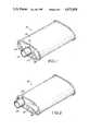
- FIG. 1is a perspective view of the muffler of the subject invention showing the outlet end thereof.
- FIG. 2is a second perspective view of the muffler of the subject invention showing the inlet end.
- FIG. 3is a cross-sectional view of the muffler of the subject invention.
- FIG. 4is an end view of the outlet end muffler of the subject invention.
- FIG. 5is a second end view of the inlet end muffler of the subject invention.
- FIG. 6is a cross-sectional view taken along line 6--6 in FIG. 3.
- the high performance muffler of the subject inventionis indicated generally by the numeral 10 in FIGS. 1 and 2.
- the muffler 10is a generally elongated structure having an outlet end cap 12 as shown in FIG. 1 and an inlet end cap 14 as shown in FIG. 2.
- the outlet and inlet end caps 12 and 14are of generally eliptical shape and are disposed generally parallel to one another and generally orthogonal to the centerline of the muffler 10.
- An outer shell 16defines the outer surface of the muffler 10. More particularly, the outer shell 16 defines an elongated tube of eliptical cross section, the opposed ends of which are connected respectively to the opposed outlet and inlet end caps 12 and 14.
- the connection between the outer shell 16 and the outlet and inlet end caps 12 and 14preferably is mechanical, and is formed by an interlocking of the respective edges.
- the outlet end cap 12 of the high performance muffler 10is provided with a generally centrally disposed circular aperture 18 through which a tubular outlet nipple 20 extends.
- the outlet nipple 20will be connected to the tail pipe of the vehicle on which the muffler 10 is mounted.
- the inlet end cap 14includes a generally circular aperture 22 through which a tubular inlet nipple 24 extends.
- the inlet nipple 24is offset relative to the centerline of the muffler 10.
- the inlet nipple 24will be connected to the exhaust pipe of the vehicle.
- the muffler 10includes internal baffles 26 and 28 which are of generally the same eliptical cross-sectional configuration as the opposed inlet and outlet end caps 14 and 12 respectively. More particularly, the internal baffles 26 and 28 are disposed parallel to the inlet and outlet end caps 14 and 12 and are mounted in supporting contact with the outer shell 16 of the muffler.
- an inlet end flow chamber 30is defined intermediate the inlet end cap 14 and the internal baffle 26.
- an outlet end flow chamber 32is defined intermediate the outlet end cap 12 and the internal baffle 28.
- a low frequency tuning chamber 34is defined intermediate the baffles 26 and 28.
- the internal baffles 26 and 28are provided respectively with apertures 36 and 38 which are disposed in an off center position relative to the centerline of the muffler 10, but which are generally aligned with the aperture 22 in the inlet end cap 14.
- the inlet nipple 24extends through the aperture 22 in the inlet end cap 14 and defines an inlet tube 40 inside the muffler 10.
- the inlet tube 40extends through the apertures 36 and 38 in the baffles 26 and 28 respectively.
- the portion 42 of the inlet tube 40 disposed within the flow chamber 30includes a plurality of tuning apertures 43.
- the portion 44 of the inlet tube 40 within the low frequency tuning chamber 34includes a plurality of perforations or louvers 45. The size and density of the louvers 45 are selected to achieve the desired attenuation of low frequency noise produced by the exhaust gases passing through the inlet tube 40.
- the internal baffles 26 and 28are provided with apertures 46 and 48 respectively.
- the apertures 46 and 48are off center an amount substantially equal to the off center alignment of the apertures 36 and 38.
- a transfer tube 50extends between the baffles 26 and 28 and is connected thereto at the respective apertures 46 and 48.
- the transfer tube 50provides for communication between the outlet end flow chamber 32 and the inlet end flow chamber 30.
- the transfer tube 50also is provided with an array of perforations or louvers 52, the size and density of which is selected to achieve the preferred low frequency noise attenuation.
- the baffles 26 and 28also are provided with apertures 56 and 58 respectively, which are centrally aligned with the aperture 18 in the outlet end cap 12.
- the outlet nipple 20extends into the internal portion of the muffler and defines an outlet tube 60 therein. More particularly, the outlet tube 60 includes a portion 62 of solid wall construction disposed within the outlet end flow chamber 32. Additionally, the portion 64 of the outlet tube 60 disposed intermediate the baffles 26 and 28 is defined by an array of perforations 66.
- the portion 64 of the outlet tube 60 between the baffles 26 and 28is surrounded by a solid wall generally tubular structure 68 which defines a high frequency tuning chamber 70 intermediate the tubular member 68 and the portion 64 of outlet tube 60. More particularly, the tubular member 68 is provided with pinches 71 adjacent the opposed ends thereof to achieve a secure interfit with the outlet tube 60 adjacent the baffles 26 and 28 respectively.
- the tubular member 68is formed to have a generally eliptical cross section as shown in FIG. 6.
- the long axis of the eliptically cross-sectioned tubular member 68is aligned orthogonal to the long axis of the eliptically cross-sectioned muffler 10.
- the short axis of the eliptically cross-sectioned tubular member 68will fit within the very limited space between the inlet tube 40 and the transfer tube 50.
- the long axis of the eliptically cross-sectioned tubular member 68will be able to extend substantially the entire distance toward the opposed surfaces of the outer shell 16. This greater height of the eliptical tubular member 68 enables an effective volume for the high frequency tuning chamber 70.
- the volume of the high frequency tuning chamber 70is packed with a sound absorbing material 74, such as fiberglass.
- the fiberglasswill contribute to the sound attenuation performance of the muffler 10 for at least the initial part of the life of muffler 10.
- the high volume of hot exhaust gases passing through muffler 10tends to break down the known sound absorbing materials.
- sound absorbing materialssuch as the absorbant packing 74 may eventually be drawn through the apertures 66 and blown from the muffler.
- the high frequency tuning chamber 70will remain effective even if all of the absorbing material 74 is evacuated therefrom.
- the muffler 10will have a low frequency tuning chamber 34 and a high frequency tuning chamber 70 its entire life.
- the exhaust gasestravel from the engine through the exhaust pipe and into the inlet nipple 24. These gases will flow through the inlet tube 40 and toward the outlet end flow chamber 32. The exhaust gases will then circulate through the outlet end flow chamber 32 and into the transfer tube 50.
- the transfer tube 50provides for the communication of the exhaust gases between the outlet end flow chamber 32 and the inlet end flow chamber 30. As the exhaust gases move through the portion 44 of inlet tube 40 and through the transfer tube 50, a limited amount of fluid communication is enabled through the respective perforations 45 and 52 into the low frequency tuning chamber 34. As noted previously, the dimensions of the low frequency tuning chamber and of the perforations 45 and 52 are selected to achieve the desired low frequency sound attenuation.
- the exhaust gases leaving the transfer tube 50will swirl through the inlet end flow chamber 30 and eventually into the outlet tube 60 to flow toward the exhaust pipe of the vehicle. The movement of the exhaust gases through the portion 64 of the outlet tube 60 will enable high frequency sound attenuation.
- the exact flow pattern of exhaust gases in the flow chambers 30 and 32is not known precisely. However, it is known that the precise flow patterns within the flow chambers 30 and 32 will vary in accordance with engine operating speeds and condition. It also is known that a substantial amount of turbulence and swirling action occurs as the exhaust gases move through the flow chambers 30 and 32. This turbulence can increase the back pressure produced by the muffler, and can thereby affect engine performance. On the other hand, back pressure can be reduced and engine performance improved if the flow of exhaust gases through the flow chambers 30 and 32 can be made more laminar.
- a more laminar exhaust gas flowis achieved in the outlet end flow chamber 32 of the subject high performance muffler 10 by an outwardly bowed portion 80 in the outlet end cap 12 generally opposite the inlet tube 40.
- the outwardly bowed portion 80is stamp formed in the outlet end cap 12 and defines a generally spherical section with a diameter equal to or greater than the diameter of the inlet tube. More particularly, this outwardly bowed portion contributes to the directional change that must occur in the exhaust gases exiting the inlet tube 40.
- a second outwardly bowed portion 82is stamp formed therein.
- the outwardly bowed portion 82is substantially identical to the outwardly bowed portion 80 described above. In a typical installation of muffler 10, it is believed that the outwardly bowed portion 82 will have a somewhat smaller effect on air flow than the outwardly bowed portion 80. However, in some situations, the muffler 10 may be installed in a reversed position to accommodate unique space limitations on the vehicle. On these installations, the outwardly bowed portion 82 will be more important in achieving the desired laminar flow through the outlet end flow chamber 32.
- the outwardly bowed portions 80 and 82are spaced from the outlet nipple 20 by a distance "a" which typically is 0.25 inch or more. Similarly, the outwardly bowed portions 80 and 82 are spaced from the outer shell 16 by a distance "b" of approximately 0.375 inch or more. This spacing insures that the mechanical connections of the outlet end cap 12 to the outer shell 16 and to the outlet nipple 20 are not complicated by the presence of an arcuate surface.
- the inlet end cap 14is provided with outwardly bowed portion 84 which is functionally similar to the outwardly bowed portions 80 and 82 described with reference to the outlet end cap 12. More particularly, the outwardly bowed portion 84 will contribute to a laminar directional change of exhaust gases flowing from the transfer tube 50 through the inlet end flow chamber 30 and into the outlet tube 60.
- the outwardly bowed portion 84is of generally elongated "teardrop" shape such that the end 86 thereof opposite the transfer tube 50 is larger than the end 88 thereof opposite the outlet tube 60.
- the end 86 of the outwardly bowed portion 84defines a diameter "c" of approximately 3.00 inches, while the end 88 thereof defines a diameter of "d” of approximately 1.50 inches or about one-half the diameter at end 86. Furthermore, the end 86 is approximately 0.375 inch deep, as indicated by dimension "e” while the end 88 is approximately 0.188 inch deep as indicated by dimension "f” or about one-half the depth at end 86.
- This unique configurationhas been found to be particularly effective in achieving a laminar flow of exhaust gases from the transfer tube 50 to the outlet tube 60.
- the outwardly bowed portion 84is spaced distance "g” of approximately 0.375 inch from the outer shell 16.
- the outwardly bowed portion 84is spaced distance "h” of approximately 0.50 inch from the inlet tube 20.
- a high performance mufflerwhich achieves a desirably low back pressure and acceptably low noise levels.
- the mufflerincludes opposed inlet and outlet end caps and a generally eliptically cross-sectioned outer shell.
- a pair of internal bafflesare disposed in spaced relationship inside the muffler to define opposed inlet end and outlet end flow chambers and a low frequency tuning chamber therebetween.
- An inlet tubeextends through the inlet end cap and through both internal baffles in an off center alignment to provide fluid communication from the engine of the vehicle to the outlet end flow chamber.
- a transfer tubeconnects the two flow chambers. The portions of the inlet tube and the transfer tube which pass through the low frequency tuning chamber are perforated.
- An outlet tubeextends through both internal baffles and the outlet end cap to provide fluid communication between the inlet end flow chamber and the tail pipe of the vehicle.
- the portion of the outlet tube disposed between the bafflesis perforated and is surrounded by a generally tubular member which defines a high frequency tuning chamber.
- the high frequency tuning chamberis of eliptical cross section, and has its long cross-sectional axis disposed orthogonal to the long axis of the eliptically cross-sectioned muffler.
- the high frequency tuning chamberis packed with a sound insulating material.
- the outlet end capis provided with generally spherical outwardly bowed portions disposed opposite the inlet tube and the transfer tube.
- the inlet end capis provided with an outwardly bowed arcuate portion opposite both the transfer tube and the outlet tube.
- the outwardly bowed portionsachieve a more laminar flow of exhaust gases through the flow chambers, thereby achieving a lower back pressure.
Landscapes
- Engineering & Computer Science (AREA)
- Chemical & Material Sciences (AREA)
- Combustion & Propulsion (AREA)
- Mechanical Engineering (AREA)
- General Engineering & Computer Science (AREA)
- Exhaust Silencers (AREA)
Abstract
Description
Claims (11)
Priority Applications (2)
| Application Number | Priority Date | Filing Date | Title |
|---|---|---|---|
| US06/861,525US4673058A (en) | 1986-05-09 | 1986-05-09 | High performance automotive muffler |
| CA000513159ACA1243264A (en) | 1986-05-09 | 1986-07-04 | High performance automotive muffler |
Applications Claiming Priority (1)
| Application Number | Priority Date | Filing Date | Title |
|---|---|---|---|
| US06/861,525US4673058A (en) | 1986-05-09 | 1986-05-09 | High performance automotive muffler |
Publications (1)
| Publication Number | Publication Date |
|---|---|
| US4673058Atrue US4673058A (en) | 1987-06-16 |
Family
ID=25336048
Family Applications (1)
| Application Number | Title | Priority Date | Filing Date |
|---|---|---|---|
| US06/861,525Expired - LifetimeUS4673058A (en) | 1986-05-09 | 1986-05-09 | High performance automotive muffler |
Country Status (2)
| Country | Link |
|---|---|
| US (1) | US4673058A (en) |
| CA (1) | CA1243264A (en) |
Cited By (36)
| Publication number | Priority date | Publication date | Assignee | Title |
|---|---|---|---|---|
| EP0682172A1 (en)* | 1994-05-14 | 1995-11-15 | ERNST-APPARATEBAU GmbH & Co. | Exhaust silencer |
| US5783782A (en)* | 1996-10-29 | 1998-07-21 | Tenneco Automotive Inc. | Multi-chamber muffler with selective sound absorbent material placement |
| US6053276A (en)* | 1998-06-09 | 2000-04-25 | D'amico, Jr.; John | Muffler packing method with injection of cartrided continuous filament fiberglass |
| US6068082A (en)* | 1997-11-21 | 2000-05-30 | D'amico, Jr.; John | Muffler packing method and apparatus |
| WO2000040841A1 (en)* | 1998-12-30 | 2000-07-13 | Volvo Personvagnar Ab | Perforated end pipe of silencer unit |
| US6135237A (en)* | 1998-04-03 | 2000-10-24 | Arvin Industries, Inc. | Stamp-formed muffler |
| US6415889B1 (en) | 1998-01-30 | 2002-07-09 | Arvinmeritor, Inc. | Stamped-formed muffler apparatus and assembly process |
| US6427802B1 (en)* | 1998-05-26 | 2002-08-06 | Sango Co., Ltd. | Muffler |
| US20040094360A1 (en)* | 2002-11-06 | 2004-05-20 | Calsonic Kansei Corporation | Acoustic dumper for exhaust system |
| US20040182643A1 (en)* | 2003-02-20 | 2004-09-23 | Youhei Toyoshima | Muffler |
| US20050031322A1 (en)* | 2003-08-04 | 2005-02-10 | David Boyle | Compressor control system for a portable ventilator |
| US20050051168A1 (en)* | 2003-08-04 | 2005-03-10 | Devries Douglas F. | Portable ventilator system |
| US20050112013A1 (en)* | 2003-08-04 | 2005-05-26 | Pulmonetic Systems, Inc. | Method and apparatus for reducing noise in a roots-type blower |
| US20050166921A1 (en)* | 2003-08-04 | 2005-08-04 | Pulmonetic Systems, Inc. | Method and apparatus for attenuating compressor noise |
| US20050224283A1 (en)* | 2002-02-20 | 2005-10-13 | Sango Co. Ltd. | Internal combustion engine silencer |
| US20060113145A1 (en)* | 2004-11-30 | 2006-06-01 | Honda Motor Co., Ltd. | Fuel cell vehicle |
| US20060249153A1 (en)* | 2003-08-04 | 2006-11-09 | Pulmonetic Systems, Inc. | Mechanical ventilation system utilizing bias valve |
| US20070125594A1 (en)* | 2005-12-01 | 2007-06-07 | Hill William E | Muffler assembly with sound absorbing member |
| US20090000863A1 (en)* | 2007-06-28 | 2009-01-01 | Share Win Industry Co., Ltd. | Exhaust pipe |
| US20090142213A1 (en)* | 2007-12-03 | 2009-06-04 | Pulmonetic Systems, Inc. | Roots-type blower reduced acoustic signature method and apparatus |
| US20090250059A1 (en)* | 2008-04-08 | 2009-10-08 | Pulmonetic Systems, Inc. | Flow sensor |
| US20100000821A1 (en)* | 2006-08-10 | 2010-01-07 | Woodrow Woods | Marine muffler with angularly disposed internal baffle |
| US20100116585A1 (en)* | 2006-08-10 | 2010-05-13 | Woodrow Woods | Marine muffler with angularly disposed internal baffle |
| US20110083924A1 (en)* | 2009-10-08 | 2011-04-14 | Park Kichul | Muffler for vehicle |
| US8156937B2 (en) | 2003-08-04 | 2012-04-17 | Carefusion 203, Inc. | Portable ventilator system |
| US8671671B1 (en) | 2011-07-14 | 2014-03-18 | Northern California Diagnostic Laboratories | Exhaust system for an internal combustion engine |
| US8707689B1 (en) | 2011-07-14 | 2014-04-29 | Northern California Diagnostic Laboratories, Inc. | Exhaust system for an internal combustion engine |
| US8820475B2 (en)* | 2012-12-05 | 2014-09-02 | Caterpillar Inc. | Exhaust muffler |
| US8905188B2 (en)* | 2012-11-23 | 2014-12-09 | Hyundai Motor Company | Muffler for motor vehicle |
| US8985270B2 (en) | 2013-03-11 | 2015-03-24 | Molded Acoustical Products Of Easton, Inc. | Clean burn muffler packing with stitched fiberglass envelope |
| US20170067379A1 (en)* | 2014-02-25 | 2017-03-09 | Bombardier Recreational Products Inc. | Muffler for an exhaust system of an internal combustion engine |
| US9631527B2 (en)* | 2015-04-23 | 2017-04-25 | Honda Motor Co., Ltd. | Exhaust system |
| US9758032B2 (en)* | 2015-05-29 | 2017-09-12 | Eberspächer Exhaust Technology GmbH & Co. KG | Exhaust muffler for transverse installation in a vehicle |
| EP3321486A1 (en)* | 2016-11-09 | 2018-05-16 | Yamaha Hatsudoki Kabushiki Kaisha | Straddled vehicle |
| CN112049710A (en)* | 2019-06-06 | 2020-12-08 | 卡特彼勒公司 | Exhaust muffler device |
| US11242782B2 (en)* | 2019-01-31 | 2022-02-08 | R&R Holding & Leasing | Muffler |
Citations (7)
| Publication number | Priority date | Publication date | Assignee | Title |
|---|---|---|---|---|
| US2041767A (en)* | 1931-06-20 | 1936-05-26 | Burgess Lab Inc C F | Silencer |
| US2088296A (en)* | 1935-04-05 | 1937-07-27 | Hayes Ind Inc | Muffler |
| US3289786A (en)* | 1965-05-17 | 1966-12-06 | Walker Mfg Co | Muffler with return bend tuning passage |
| US3389764A (en)* | 1966-07-18 | 1968-06-25 | Walker Mfg Co | Muffler with extended chamber |
| US3741336A (en)* | 1971-06-10 | 1973-06-26 | Tenneco Inc | Expansion type silencer |
| US4381045A (en)* | 1981-02-02 | 1983-04-26 | Cycles Peugeot | Exhaust gas silencer for a heat engine |
| US4467887A (en)* | 1981-11-14 | 1984-08-28 | Shelburne Incorporated | Exhaust mufflers for internal combustion engines |
- 1986
- 1986-05-09USUS06/861,525patent/US4673058A/ennot_activeExpired - Lifetime
- 1986-07-04CACA000513159Apatent/CA1243264A/ennot_activeExpired
Patent Citations (7)
| Publication number | Priority date | Publication date | Assignee | Title |
|---|---|---|---|---|
| US2041767A (en)* | 1931-06-20 | 1936-05-26 | Burgess Lab Inc C F | Silencer |
| US2088296A (en)* | 1935-04-05 | 1937-07-27 | Hayes Ind Inc | Muffler |
| US3289786A (en)* | 1965-05-17 | 1966-12-06 | Walker Mfg Co | Muffler with return bend tuning passage |
| US3389764A (en)* | 1966-07-18 | 1968-06-25 | Walker Mfg Co | Muffler with extended chamber |
| US3741336A (en)* | 1971-06-10 | 1973-06-26 | Tenneco Inc | Expansion type silencer |
| US4381045A (en)* | 1981-02-02 | 1983-04-26 | Cycles Peugeot | Exhaust gas silencer for a heat engine |
| US4467887A (en)* | 1981-11-14 | 1984-08-28 | Shelburne Incorporated | Exhaust mufflers for internal combustion engines |
Cited By (62)
| Publication number | Priority date | Publication date | Assignee | Title |
|---|---|---|---|---|
| EP0682172A1 (en)* | 1994-05-14 | 1995-11-15 | ERNST-APPARATEBAU GmbH & Co. | Exhaust silencer |
| US5783782A (en)* | 1996-10-29 | 1998-07-21 | Tenneco Automotive Inc. | Multi-chamber muffler with selective sound absorbent material placement |
| US6068082A (en)* | 1997-11-21 | 2000-05-30 | D'amico, Jr.; John | Muffler packing method and apparatus |
| US6415889B1 (en) | 1998-01-30 | 2002-07-09 | Arvinmeritor, Inc. | Stamped-formed muffler apparatus and assembly process |
| US6135237A (en)* | 1998-04-03 | 2000-10-24 | Arvin Industries, Inc. | Stamp-formed muffler |
| US6427802B1 (en)* | 1998-05-26 | 2002-08-06 | Sango Co., Ltd. | Muffler |
| US6053276A (en)* | 1998-06-09 | 2000-04-25 | D'amico, Jr.; John | Muffler packing method with injection of cartrided continuous filament fiberglass |
| WO2000040841A1 (en)* | 1998-12-30 | 2000-07-13 | Volvo Personvagnar Ab | Perforated end pipe of silencer unit |
| US6629580B2 (en) | 1998-12-30 | 2003-10-07 | Volvo Personvagnar Ab | Perforated end pipe of silencer unit |
| US20050224283A1 (en)* | 2002-02-20 | 2005-10-13 | Sango Co. Ltd. | Internal combustion engine silencer |
| US20040094360A1 (en)* | 2002-11-06 | 2004-05-20 | Calsonic Kansei Corporation | Acoustic dumper for exhaust system |
| US20040182643A1 (en)* | 2003-02-20 | 2004-09-23 | Youhei Toyoshima | Muffler |
| US7503427B2 (en)* | 2003-02-20 | 2009-03-17 | Calsonic Kansei Corporation | Muffler |
| US20060249153A1 (en)* | 2003-08-04 | 2006-11-09 | Pulmonetic Systems, Inc. | Mechanical ventilation system utilizing bias valve |
| US20050051168A1 (en)* | 2003-08-04 | 2005-03-10 | Devries Douglas F. | Portable ventilator system |
| US20050112013A1 (en)* | 2003-08-04 | 2005-05-26 | Pulmonetic Systems, Inc. | Method and apparatus for reducing noise in a roots-type blower |
| US8156937B2 (en) | 2003-08-04 | 2012-04-17 | Carefusion 203, Inc. | Portable ventilator system |
| US20060213518A1 (en)* | 2003-08-04 | 2006-09-28 | Devries Douglas F | Portable ventilator system |
| US8118024B2 (en) | 2003-08-04 | 2012-02-21 | Carefusion 203, Inc. | Mechanical ventilation system utilizing bias valve |
| US20070000490A1 (en)* | 2003-08-04 | 2007-01-04 | Devries Douglas F | Portable ventilator system |
| US7188621B2 (en) | 2003-08-04 | 2007-03-13 | Pulmonetic Systems, Inc. | Portable ventilator system |
| US8297279B2 (en) | 2003-08-04 | 2012-10-30 | Carefusion 203, Inc. | Portable ventilator system |
| US20080053438A1 (en)* | 2003-08-04 | 2008-03-06 | Devries Douglas F | Portable ventilator system |
| US10118011B2 (en) | 2003-08-04 | 2018-11-06 | Carefusion 203, Inc. | Mechanical ventilation system utilizing bias valve |
| US20050166921A1 (en)* | 2003-08-04 | 2005-08-04 | Pulmonetic Systems, Inc. | Method and apparatus for attenuating compressor noise |
| US7527053B2 (en) | 2003-08-04 | 2009-05-05 | Cardinal Health 203, Inc. | Method and apparatus for attenuating compressor noise |
| US9126002B2 (en) | 2003-08-04 | 2015-09-08 | Carefusion 203, Inc. | Mechanical ventilation system utilizing bias valve |
| US8683997B2 (en) | 2003-08-04 | 2014-04-01 | Carefusion 203, Inc. | Portable ventilator system |
| US7607437B2 (en) | 2003-08-04 | 2009-10-27 | Cardinal Health 203, Inc. | Compressor control system and method for a portable ventilator |
| US20050031322A1 (en)* | 2003-08-04 | 2005-02-10 | David Boyle | Compressor control system for a portable ventilator |
| US8522780B2 (en) | 2003-08-04 | 2013-09-03 | Carefusion 203, Inc. | Portable ventilator system |
| US8677995B2 (en) | 2003-08-04 | 2014-03-25 | Carefusion 203, Inc. | Compressor control system for a portable ventilator |
| US8627819B2 (en) | 2003-08-04 | 2014-01-14 | Carefusion 203, Inc. | Portable ventilator system |
| US7694778B2 (en)* | 2004-11-30 | 2010-04-13 | Honda Motor Co., Ltd. | Fuel cell vehicle |
| US20060113145A1 (en)* | 2004-11-30 | 2006-06-01 | Honda Motor Co., Ltd. | Fuel cell vehicle |
| US20070125594A1 (en)* | 2005-12-01 | 2007-06-07 | Hill William E | Muffler assembly with sound absorbing member |
| US20100000821A1 (en)* | 2006-08-10 | 2010-01-07 | Woodrow Woods | Marine muffler with angularly disposed internal baffle |
| US7942238B2 (en)* | 2006-08-10 | 2011-05-17 | Woodrow Woods | Marine muffler with angularly disposed internal baffle |
| US7905322B2 (en)* | 2006-08-10 | 2011-03-15 | Woodrow Woods | Marine muffler with angularly disposed internal baffle |
| US20100116585A1 (en)* | 2006-08-10 | 2010-05-13 | Woodrow Woods | Marine muffler with angularly disposed internal baffle |
| US20090000863A1 (en)* | 2007-06-28 | 2009-01-01 | Share Win Industry Co., Ltd. | Exhaust pipe |
| US7997885B2 (en) | 2007-12-03 | 2011-08-16 | Carefusion 303, Inc. | Roots-type blower reduced acoustic signature method and apparatus |
| US20090142213A1 (en)* | 2007-12-03 | 2009-06-04 | Pulmonetic Systems, Inc. | Roots-type blower reduced acoustic signature method and apparatus |
| US20090250059A1 (en)* | 2008-04-08 | 2009-10-08 | Pulmonetic Systems, Inc. | Flow sensor |
| US9713438B2 (en) | 2008-04-08 | 2017-07-25 | Carefusion 203, Inc. | Flow sensor |
| US8888711B2 (en) | 2008-04-08 | 2014-11-18 | Carefusion 203, Inc. | Flow sensor |
| US9375166B2 (en) | 2008-04-08 | 2016-06-28 | Carefusion 203, Inc. | Flow sensor |
| US20110083924A1 (en)* | 2009-10-08 | 2011-04-14 | Park Kichul | Muffler for vehicle |
| US8671671B1 (en) | 2011-07-14 | 2014-03-18 | Northern California Diagnostic Laboratories | Exhaust system for an internal combustion engine |
| US8707689B1 (en) | 2011-07-14 | 2014-04-29 | Northern California Diagnostic Laboratories, Inc. | Exhaust system for an internal combustion engine |
| US8905188B2 (en)* | 2012-11-23 | 2014-12-09 | Hyundai Motor Company | Muffler for motor vehicle |
| US8820475B2 (en)* | 2012-12-05 | 2014-09-02 | Caterpillar Inc. | Exhaust muffler |
| US8985270B2 (en) | 2013-03-11 | 2015-03-24 | Molded Acoustical Products Of Easton, Inc. | Clean burn muffler packing with stitched fiberglass envelope |
| US9267406B2 (en) | 2013-03-11 | 2016-02-23 | Molded Acoustical Products Of Easton, Inc. | Clean burn muffler packing with stitched fiberglass envelope |
| US20170067379A1 (en)* | 2014-02-25 | 2017-03-09 | Bombardier Recreational Products Inc. | Muffler for an exhaust system of an internal combustion engine |
| US9631527B2 (en)* | 2015-04-23 | 2017-04-25 | Honda Motor Co., Ltd. | Exhaust system |
| US9758032B2 (en)* | 2015-05-29 | 2017-09-12 | Eberspächer Exhaust Technology GmbH & Co. KG | Exhaust muffler for transverse installation in a vehicle |
| EP3321486A1 (en)* | 2016-11-09 | 2018-05-16 | Yamaha Hatsudoki Kabushiki Kaisha | Straddled vehicle |
| US11242782B2 (en)* | 2019-01-31 | 2022-02-08 | R&R Holding & Leasing | Muffler |
| US11746681B2 (en) | 2019-01-31 | 2023-09-05 | R&R Holding & Leasing | Muffler |
| CN112049710A (en)* | 2019-06-06 | 2020-12-08 | 卡特彼勒公司 | Exhaust muffler device |
| US11434794B2 (en)* | 2019-06-06 | 2022-09-06 | Caterpillar Inc. | Exhaust sound attenuation device |
Also Published As
| Publication number | Publication date |
|---|---|
| CA1243264A (en) | 1988-10-18 |
Similar Documents
| Publication | Publication Date | Title |
|---|---|---|
| US4673058A (en) | High performance automotive muffler | |
| US4909348A (en) | Stamp formed exhaust muffler with conformal outer shell | |
| EP0268728B1 (en) | Stamp formed muffler | |
| US4736817A (en) | Stamp formed muffler | |
| US4821840A (en) | Stamp formed exhaust muffler with conformal outer shell | |
| CA2030407C (en) | Stamp formed muffler with low back pressure | |
| US4109753A (en) | Muffler assembly | |
| JP2609875B2 (en) | Exhaust muffler | |
| US5783782A (en) | Multi-chamber muffler with selective sound absorbent material placement | |
| US5252788A (en) | Stamp formed muffler with in-line expansion chamber and arcuately formed effective flow tubes | |
| EP0975859B1 (en) | Improved muffler with partition array | |
| US7549511B2 (en) | Exhaust sound and emission control systems | |
| US8439159B1 (en) | Exhaust muffler for internal combustion engines | |
| US3454129A (en) | Sound muting and filtering device | |
| US20090014238A1 (en) | Muffler | |
| JPH0255820A (en) | Assembly of catalyst converter and exhaust muffler | |
| US4006793A (en) | Engine muffler apparatus providing acoustic silencer | |
| US4953660A (en) | Muffler with two part housing and flow tubes | |
| AU2232099A (en) | Improved high performance muffler | |
| EP1015739B1 (en) | Noise attenuating apparatus | |
| US11614009B2 (en) | Vehicle exhaust system | |
| US4153136A (en) | Muffler | |
| US5717173A (en) | Exhaust mufflers with stamp formed internal components and method of manufacture | |
| CA1198987A (en) | Muffler | |
| JPH0240243Y2 (en) |
Legal Events
| Date | Code | Title | Description |
|---|---|---|---|
| AS | Assignment | Owner name:G ENTERPRISES LIMITED, 172 BETHRIDGE ROAD, REXDALE Free format text:ASSIGNMENT OF ASSIGNORS INTEREST.;ASSIGNORS:ROBERTS, PETER;CHUNG, SYDNEY;REEL/FRAME:004570/0137 Effective date:19860430 | |
| STCF | Information on status: patent grant | Free format text:PATENTED CASE | |
| AS | Assignment | Owner name:MR. GASKET COMPANY, A CORP. OF OHIO Free format text:ASSIGNMENT OF ASSIGNORS INTEREST.;ASSIGNOR:G ENTERPRISES LIMITED;REEL/FRAME:004777/0453 Effective date:19871022 | |
| FEPP | Fee payment procedure | Free format text:PAYOR NUMBER ASSIGNED (ORIGINAL EVENT CODE: ASPN); ENTITY STATUS OF PATENT OWNER: LARGE ENTITY | |
| FPAY | Fee payment | Year of fee payment:4 | |
| AS | Assignment | Owner name:INTERNATIONAL AUTOMOBILE PRODUCTS HOLDINGS CORP., Free format text:SECURITY INTEREST;ASSIGNOR:A P PARTS MANUFACUTURING COMPANY, A CORP. OF DE;REEL/FRAME:005659/0117 Effective date:19910228 | |
| FEPP | Fee payment procedure | Free format text:PAYER NUMBER DE-ASSIGNED (ORIGINAL EVENT CODE: RMPN); ENTITY STATUS OF PATENT OWNER: LARGE ENTITY Free format text:PAYOR NUMBER ASSIGNED (ORIGINAL EVENT CODE: ASPN); ENTITY STATUS OF PATENT OWNER: LARGE ENTITY | |
| AS | Assignment | Owner name:AP PARTS MANUFACTURING COMPANY, OHIO Free format text:RELEASED BY SECURED PARTY;ASSIGNOR:INTERNATIONAL AUTOMOBILE PRODUCTS HOLDINGS CORP.;REEL/FRAME:006348/0803 Effective date:19920331 | |
| FPAY | Fee payment | Year of fee payment:8 | |
| FPAY | Fee payment | Year of fee payment:12 | |
| AS | Assignment | Owner name:WACHOVIA BANK, NATIONAL ASSOCIATION, AS COLLATERAL Free format text:AMENDMENT TO SECURITY INTEREST IN UNITED STATES PATENTS;ASSIGNORS:TENNECO AUTOMOTIVE INC.;TENNECO AUTOMOTIVE OPERATING COMPANY INC.;TENNECO INTERNATIONAL HOLDING CORP.;AND OTHERS;REEL/FRAME:015953/0848 Effective date:20050428 | |
| AS | Assignment | Owner name:JPMORGAN CHASE BANK,NEW YORK Free format text:AMENDMENT TO SECURITY INTEREST IN UNITED STATES PATENTS;ASSIGNORS:TENNECO AUTOMOTIVE OPERATING COMPANY INC.;TENNECO INTERNATIONAL HOLDING CORP.;TENNECO GLOBAL HOLDINGS INC.;AND OTHERS;REEL/FRAME:019009/0247 Effective date:20070312 Owner name:U.S. BANK NATIONAL ASSOCIATION,TEXAS Free format text:AMENDMENT TO SECURITY INTEREST IN UNITED STATES PATENTS;ASSIGNORS:TENNECO INC.;TENNECO AUTOMOTIVE OPERATING COMPANY INC.;TENNECO INTERNATIONAL HOLDING CORP.;AND OTHERS;REEL/FRAME:019009/0381 Effective date:20070308 Owner name:JPMORGAN CHASE BANK, NEW YORK Free format text:AMENDMENT TO SECURITY INTEREST IN UNITED STATES PATENTS;ASSIGNORS:TENNECO AUTOMOTIVE OPERATING COMPANY INC.;TENNECO INTERNATIONAL HOLDING CORP.;TENNECO GLOBAL HOLDINGS INC.;AND OTHERS;REEL/FRAME:019009/0247 Effective date:20070312 Owner name:U.S. BANK NATIONAL ASSOCIATION, TEXAS Free format text:AMENDMENT TO SECURITY INTEREST IN UNITED STATES PATENTS;ASSIGNORS:TENNECO INC.;TENNECO AUTOMOTIVE OPERATING COMPANY INC.;TENNECO INTERNATIONAL HOLDING CORP.;AND OTHERS;REEL/FRAME:019009/0381 Effective date:20070308 | |
| AS | Assignment | Owner name:TENNECO GLOBAL HOLDINGS INC., ILLINOIS Free format text:CONFIRMATION OF TERMINATION AND RELEASE OF SECURITY INTEREST IN PATENT RIGHTS (R/F 19009/0247);ASSIGNOR:JPMORGAN CHASE BANK, N.A., AS ADMINISTRATIVE AGENT;REEL/FRAME:055429/0284 Effective date:20210226 Owner name:CLEVITE INDUSTRIES INC., ILLINOIS Free format text:CONFIRMATION OF TERMINATION AND RELEASE OF SECURITY INTEREST IN PATENT RIGHTS (R/F 19009/0247);ASSIGNOR:JPMORGAN CHASE BANK, N.A., AS ADMINISTRATIVE AGENT;REEL/FRAME:055429/0284 Effective date:20210226 Owner name:TENNECO INC. (FORMERLY KNOWN AS TENNECO AUTOMOTIVE INC.), ILLINOIS Free format text:CONFIRMATION OF TERMINATION AND RELEASE OF SECURITY INTEREST IN PATENT RIGHTS (R/F 19009/0247);ASSIGNOR:JPMORGAN CHASE BANK, N.A., AS ADMINISTRATIVE AGENT;REEL/FRAME:055429/0284 Effective date:20210226 Owner name:THE PULLMAN COMPANY, ILLINOIS Free format text:CONFIRMATION OF TERMINATION AND RELEASE OF SECURITY INTEREST IN PATENT RIGHTS (R/F 19009/0247);ASSIGNOR:JPMORGAN CHASE BANK, N.A., AS ADMINISTRATIVE AGENT;REEL/FRAME:055429/0284 Effective date:20210226 Owner name:TENNECO INTERNATIONAL HOLDING CORP., ILLINOIS Free format text:CONFIRMATION OF TERMINATION AND RELEASE OF SECURITY INTEREST IN PATENT RIGHTS (R/F 19009/0247);ASSIGNOR:JPMORGAN CHASE BANK, N.A., AS ADMINISTRATIVE AGENT;REEL/FRAME:055429/0284 Effective date:20210226 Owner name:TENNECO AUTOMOTIVE OPERATING COMPANY INC., ILLINOIS Free format text:CONFIRMATION OF TERMINATION AND RELEASE OF SECURITY INTEREST IN PATENT RIGHTS (R/F 19009/0247);ASSIGNOR:JPMORGAN CHASE BANK, N.A., AS ADMINISTRATIVE AGENT;REEL/FRAME:055429/0284 Effective date:20210226 Owner name:TMC TEXAS INC., ILLINOIS Free format text:CONFIRMATION OF TERMINATION AND RELEASE OF SECURITY INTEREST IN PATENT RIGHTS (R/F 19009/0247);ASSIGNOR:JPMORGAN CHASE BANK, N.A., AS ADMINISTRATIVE AGENT;REEL/FRAME:055429/0284 Effective date:20210226 |