US4673043A - Hammer having a protective cover - Google Patents
Hammer having a protective coverDownload PDFInfo
- Publication number
- US4673043A US4673043AUS06/812,402US81240285AUS4673043AUS 4673043 AUS4673043 AUS 4673043AUS 81240285 AUS81240285 AUS 81240285AUS 4673043 AUS4673043 AUS 4673043A
- Authority
- US
- United States
- Prior art keywords
- hammer
- swing arms
- housing
- cover
- stops
- Prior art date
- Legal status (The legal status is an assumption and is not a legal conclusion. Google has not performed a legal analysis and makes no representation as to the accuracy of the status listed.)
- Expired - Lifetime
Links
Images
Classifications
- B—PERFORMING OPERATIONS; TRANSPORTING
- B25—HAND TOOLS; PORTABLE POWER-DRIVEN TOOLS; MANIPULATORS
- B25D—PERCUSSIVE TOOLS
- B25D17/00—Details of, or accessories for, portable power-driven percussive tools
- B25D17/04—Handles; Handle mountings
- B25D17/043—Handles resiliently mounted relative to the hammer housing
- B—PERFORMING OPERATIONS; TRANSPORTING
- B25—HAND TOOLS; PORTABLE POWER-DRIVEN TOOLS; MANIPULATORS
- B25D—PERCUSSIVE TOOLS
- B25D17/00—Details of, or accessories for, portable power-driven percussive tools
- B25D17/11—Arrangements of noise-damping means
Definitions
- the present inventionrelates to a motor-driven hammer having an impact mechanism that is driven by the motor via a crank drive.
- the hammerhas a protective cover that is provided with handgrips and is cushioned relative to the housing of the hammer. When viewed in the upright position of operation of the hammer, the cover covers, and is spaced from, the top, both sides, and the front of the motor and the crank drive, at least relative to an operator.
- the task of the coveris to protect the operator from heat radiating from the hot motor parts, and from direct contact with these parts.
- the coveris also intended for muffling radiation of noise from the motor into the environment, and especially to the operator.
- the coverprotects the operator from current pulses, which with apparatus of this type can be caused, for example, by striking an underground cable with the bit during breaking-up operations, or, with electric hammers, by carelessly damaging the actual electrical lead on the motor, thus conveying dangerous voltage to the motor parts of the hammer.
- the handgrips for guiding the hammer on the protective coverfulfills the additional task of cushioning the grip, and hence of avoiding damaging the health of the operator and of increasing the operating comfort for the latter.
- the protective coveris supported at a number of locations on the hammer housing via simple springs. As a result, under certain operating conditions, the cover can twist or tilt relative to the housing. The cover is then in direct contact with the housing, and to a large extent loses its ability to fulfill the aforementioned tasks. With the heretofore known hammers, the ability of the protective cover to function is also extensively impaired as the operating pressure exerted upon the handgrips by the operator increases.
- An object of the present inventiontherefore is to provide a hammer of the aforementioned general type that is designed in such a way that the protective cover has no possibility of coming into contact with the hammer housing, that both the left and the right handgrip are always uniformly cushioned independent of the size of the operator, that jarring blows of the cushioned cover with the housing are precluded even under high pressures and pulling forces exerted by the operator upon the handgrips, and that nevertheless the cushioning of the handgrips is very soft in the normal operating range during customary applications, so that the operator can hardly feel any vibration.
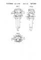
- FIG. 1shows a first embodiment of the inventive hammer from the rear, i.e. from the viewpoint of the operator, with the protective cover in section;
- FIG. 2is a side view of the embodiment of FIG. 1;
- FIG. 3is a plan view of the hammer of FIGS. 1 and 2, with the top of the protective cover being cut away;
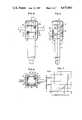
- FIG. 4shows a further embodiment of the inventive hammer, from the rear, with the protective cover again being in section;
- FIG. 5is a side view of the hammer of FIG. 4;
- FIG. 6is a plan view of the hammer of FIGS. 4 and 5, with the top of the protective cover being cut away;
- FIG. 7is a spring characteristic curve, with the spring force being plotted against the deflection, and applies to elastic foamed polyurethane that is used as the material for elastic stops of the inventive hammer.
- the hammer of the present inventionis characterized primarily by two pairs of swing arms that extend on both sides between the hammer housing and the protective cover for positively guiding the latter parallel to the longitudinal axis of the hammer.
- the swing arms of a given pair of armsare disposed parallel to one another, and are spaced apart one above the other.
- Each armhas two ends, one of which is pivotably mounted on the cover, and the other of which is pivotably mounted on the housing.
- This pivotable mountingis effected by pivot means, at least some of which are embodied in the form of soft torsion springs.
- the swing armshave a pivot range that is free except for the torsion spring effect.
- the inventive hammeris also characterized by stops for elastically delimiting this free pivot range of the swing arms. The stops cooperate in a cushioned manner, and are disposed on the housing and on the cover. The stops have a spring force that increases progressively outwardly from the free pivot range of the swing arms.
- the inventively provided and disposed swing armswhich are mounted on the protective cover and on the motor housing, effect a permanent and positive parallel guidance of the cover relative to the housing, and reliably prevent any twisting or tilting of the cover.
- the cushioning of the swing arms via torsional sleevesenables a very flat and extensively linear spring characteristic in the normal operating range.
- the delimiting of this normal operating range via elastic stops having a progressively increasing spring characteristicpermits high pulling forces and pressure to be exerted upon the handgrips beyond this normal operating range without the danger of jarring blows.
- the inventive protective coverprovides an optimum operability of hammers that up to now could not be achieved. This applies to hammers driven by a gasoline engine, as well as to hammers driven by an electric motor or other motors.
- the hammer of FIGS. 1 to 3is provided with a housing 1 that also includes the motor parts, on which other parts can be secured.
- the non-illustrated motorwhich is arranged at the top, can be a gasoline engine or an electric motor, and in principle could also be a different type of energy source, such as a hydraulic or a pneumatic motor.
- the top of the hammer housing 1is enclosed on all sides by a protective cover 2 that extends at least around the motor region, but can also extend over at least a portion of the hammer shaft 3, in which is disposed the impact mechanism.
- the cover 2is positively guided parallel to the longitudinal axis 4 of the hammer, and supports the customary handgrips 5 that are disposed on both sides.
- the cover 2also supports the supplemental handgrip 6 that is required by the operator for reversing the unit and directing the hammer.
- each of the arms 7a, 7b, 8a and 8bis provided with a shaft stub 9; these shaft stubs extend from the arms at right angles to the respective cover or housing.
- the shaft stubs 9 on the corresponding end of said armsmerely extend into bores in bearing blocks 10 disposed on the protective cover 2.
- the shaft stubs 9 on the corresponding opposite end of the swing armsare rigidly connected with torsional sleeves 11 that are secured in the hammer housing 1; the periphery of these sleeves may be rigidly secured to the housing 1.
- the torsional sleeves 11have a relatively great elasticity, so that they produce a soft shock absorption of the swing arms 7a, 7b, 8a, and 8b relative to the hammer housing 1, with the elasticity changing only slightly over a relatively large range of the reciprocal parallel displacement of the hammer housing 1 and the protective cover 2.
- the aforementioned range of movement, with soft shock absorption between the hammer housing 1 and the protective cover 2, in other words the corresponding pivot range of the swing arms,is elastically delimited by stops 12, 13 and 14, 15 that are disposed between the cover 2 and the housing 1 and cooperate in a cushioned manner.
- the stops 12, 13delimit movement in one direction
- the stops 14, 15delimit movement in the opposite direction.
- the two pairs of cooperating stops 12,13 on the one hand and 14, 15 on the other handeach comprise a rigid stop 12 or 14 that is disposed on the inside of the cover 2, and a cooperating stop 13 or 15 that is made of resilient material and is disposed on the hammer housing 1.
- These resilient stops 13 and 15are such that there results for the cooperating stops 12, 13 and 14, 15 a progressive spring characteristic, such as the one illustrated by the curve in FIG. 7.
- An example of the material that is particularly suitable for providing such a spring characteristicis elastic, foamed polyurethane.
- Elastic polyurethaneis also a particularly good material for the torsional sleeves 11, although in this case the polyurethane is not foamed.
- Both of the upper swing arms 7a, 8a, as well as both of the lower swing arms 7b, 8b,are respectively rigidly interconnected by connecting members 16 that form respective swivel brackets with the swing arms. Such a rigid interconnection of the swing arms is particularly suitable where the cover 2 does not have sufficient inherent rigidity to itself force a synchronous movement of the swing arms.
- the protective cover 2is high enough so that even when the greatest pressure or pulling is exerted upon the handgrips 5, the top of the cover 2 does not come into contact with the hammer housing 1.
- the cooperating stops 12, 13 on the one hand, and 14, 15 on the other handcan be provided with different progressive spring characteristics. It is also advisable to make the cooperating stops adjustable (not illustrated) in order to be able to adapt the spring characteristic to varying applications of the hammer.
- FIGS. 4-6coincides to a large extent to that illustrated in FIGS. 1-3.
- the differenceis merely in the arrangement of the pivot and spring points for the swing arms 7a, 7b, 8a, 8b.
- the shaft stubs 9' of both ends of the respective swing armsengage torsional sleeves 11'. At one end, these torsional sleeves are disposed in the hammer housing, and at the other end the sleeves are disposed in bearing blocks 10' provided on that wall of the cover 2 that faces the operator.
- both the upper and lower shaft stubs 9'are respectively interconnected to form continuous rods; these rods then effect the rigid interconnection between the swing arms 7a, 8a on the one hand, and 7b, 8b on the other hand.
Landscapes
- Engineering & Computer Science (AREA)
- Mechanical Engineering (AREA)
- Percussive Tools And Related Accessories (AREA)
Abstract
Description
Claims (8)
Applications Claiming Priority (2)
| Application Number | Priority Date | Filing Date | Title |
|---|---|---|---|
| DE19843447401DE3447401A1 (en) | 1984-12-24 | 1984-12-24 | HAMMER WITH COVER |
| DE3447401 | 1984-12-24 |
Publications (1)
| Publication Number | Publication Date |
|---|---|
| US4673043Atrue US4673043A (en) | 1987-06-16 |
Family
ID=6253896
Family Applications (1)
| Application Number | Title | Priority Date | Filing Date |
|---|---|---|---|
| US06/812,402Expired - LifetimeUS4673043A (en) | 1984-12-24 | 1985-12-23 | Hammer having a protective cover |
Country Status (4)
| Country | Link |
|---|---|
| US (1) | US4673043A (en) |
| EP (1) | EP0194347B1 (en) |
| JP (1) | JPS61159387A (en) |
| DE (1) | DE3447401A1 (en) |
Cited By (48)
| Publication number | Priority date | Publication date | Assignee | Title |
|---|---|---|---|---|
| US5095600A (en)* | 1989-04-01 | 1992-03-17 | Allan David T | Paving breakers and supports therefor |
| US5947211A (en)* | 1995-07-13 | 1999-09-07 | Atlas Copco Berema Aktiebolag | Vibration-damped machine driven tool |
| EP0849492A3 (en)* | 1996-12-18 | 2000-01-12 | Ingersoll-Rand Company | Parallel displacement single axis vibration absorber |
| US6082468A (en)* | 1998-04-20 | 2000-07-04 | Snap-On Tools Company | Interchangeable grips for power hand tools |
| US6286610B1 (en)* | 1997-07-15 | 2001-09-11 | Wacker-Werke Gmbh & Co. Kg | Percussion and/or drill hammer with oscillation damping |
| WO2003011532A1 (en)* | 2001-07-24 | 2003-02-13 | Robert Bosch Gmbh | Hand-held machine tool with vibration-damped handle |
| EP1166971A3 (en)* | 2000-06-27 | 2004-01-02 | Framatome Connectors International | Dampening system for tool handles |
| US6755260B1 (en)* | 1999-06-10 | 2004-06-29 | Macdonald Air Tools Limited | Pneumatic tool |
| US20040231867A1 (en)* | 2003-05-21 | 2004-11-25 | Reimund Becht | Vibration reduction apparatus for power tool and power tool incorporating such apparatus |
| EP1529602A2 (en) | 2003-11-04 | 2005-05-11 | BLACK & DECKER INC. | Vibration reduction apparatus for power tool and power tool incorporating such apparatus |
| US20050247464A1 (en)* | 2004-04-23 | 2005-11-10 | Manfred Hellbach | Power tool with a rotating and/or hammering drive mechanism |
| US20050284646A1 (en)* | 2004-06-04 | 2005-12-29 | Dorin Bacila | Vibration reduction apparatus for power tool and power tool incorporating such apparatus |
| US20060011365A1 (en)* | 2003-11-04 | 2006-01-19 | Michael Stirm | Vibration reduction apparatus for power tool and power tool incorporating such apparatus |
| WO2006021466A1 (en)* | 2004-08-26 | 2006-03-02 | Robert Bosch Gmbh | Manual machine tool handle device comprising a vibration-shielding unit |
| US20060144604A1 (en)* | 2004-12-23 | 2006-07-06 | Martin Soika | Power tool housing |
| US20060157263A1 (en)* | 2004-12-24 | 2006-07-20 | J.C. Bamford Excavators Limited | Percussion power tool apparatus |
| WO2006126944A1 (en)* | 2005-05-26 | 2006-11-30 | Atlas Copco Construction Tools Ab | Breaker tool with vibration riainnfid handle device. |
| GB2431133A (en)* | 2007-01-17 | 2007-04-18 | Black & Decker Inc | A power tool with vibration reduction apparatus |
| WO2006130940A3 (en)* | 2005-06-08 | 2007-07-26 | Embraer Aeronautica Sa | Anti-vibration coating for handles op pneumatic riveter tools used in aircraft assembly |
| CN100354073C (en)* | 2001-11-09 | 2007-12-12 | 山田机械工业有限公司 | Engine braker |
| US20080006419A1 (en)* | 2006-07-01 | 2008-01-10 | Black & Decker Inc. | Tool holder connector for powered hammer |
| US20080006423A1 (en)* | 2006-07-01 | 2008-01-10 | Black & Decker Inc. | Tool holder for a powered hammer |
| US20080006426A1 (en)* | 2006-07-01 | 2008-01-10 | Black & Decker Inc. | Powered hammer with vibration dampener |
| US20080006420A1 (en)* | 2006-07-01 | 2008-01-10 | Black & Decker Inc. | Lubricant system for powered hammer |
| US20080022817A1 (en)* | 2006-07-27 | 2008-01-31 | Axel Fischer | Hand-held power tool with a decoupling device |
| US7401661B2 (en) | 2006-07-01 | 2008-07-22 | Black & Decker Inc. | Lubricant pump for powered hammer |
| US20080190632A1 (en)* | 2003-12-10 | 2008-08-14 | Wacker Construction Equipment Ag | Percussion Hammer and/or Drill Hammer Comprising a Handle Which Can be Guided in a Linear Manner |
| US20080202785A1 (en)* | 2007-02-15 | 2008-08-28 | Axel Fischer | Hand-held power tool |
| US20080283261A1 (en)* | 2006-05-08 | 2008-11-20 | Lars Schmid | Hand-Held Power Tool with a Vibration-Damped Handle |
| US20090025950A1 (en)* | 2006-11-09 | 2009-01-29 | Hubert Steinke | Hand-held power tool with a vibration-damped rounded handle |
| EP2082844A1 (en)* | 2008-01-24 | 2009-07-29 | Black & Decker, Inc. | Hammer Drill |
| US20090277657A1 (en)* | 2001-12-21 | 2009-11-12 | Wacker Neuson Se | Drilling and/or Striking Hammer with a Lubricating Device |
| CN101415526B (en)* | 2006-04-07 | 2010-09-01 | 罗伯特·博世有限公司 | Portable power tool with vibration-damped handle |
| US20110127057A1 (en)* | 2008-05-16 | 2011-06-02 | Heiko Roehm | Portable power tool, particularly cordless screwdriver or cordless drill |
| EP2567780A1 (en)* | 2011-09-07 | 2013-03-13 | Makita Corporation | Power tool dust collecting device and power tool |
| US8590633B2 (en) | 2006-07-01 | 2013-11-26 | Black & Decker Inc. | Beat piece wear indicator for powered hammer |
| US20140332245A1 (en)* | 2011-12-23 | 2014-11-13 | Robert Bosch Gmbh | Machine Tool |
| US20170101747A1 (en)* | 2015-10-13 | 2017-04-13 | Black & Decker Inc. | Pavement Breaker |
| US9815186B2 (en) | 2014-10-09 | 2017-11-14 | Caterpillar Inc. | Shroud member for a powered hammer |
| US10675743B2 (en)* | 2017-02-23 | 2020-06-09 | The Hong Kong Polytechnic University | Passive vibration reducing apparatus |
| US20220290396A1 (en)* | 2019-08-28 | 2022-09-15 | Technische Universiteit Delft | Shaker for gentle driving of piles |
| US20230201931A1 (en)* | 2021-12-23 | 2023-06-29 | Klingelnberg Gmbh | Machine tool and method |
| US20230302597A1 (en)* | 2020-07-07 | 2023-09-28 | Seti-Tec | Carousel-type single-spindle multi-task device |
| CN116908983A (en)* | 2023-06-27 | 2023-10-20 | 昆山市建设工程质量检测中心 | Drilling direct-buried optical cable lowering anti-torsion device and method |
| US20240100673A1 (en)* | 2019-11-14 | 2024-03-28 | Hilti Aktiengesellschaft | Handle apparatus for a power tool |
| US20240157538A1 (en)* | 2021-04-07 | 2024-05-16 | Robert Bosch Gmbh | Hand-Held Power Tool Having an Activation Unit |
| US12109673B1 (en)* | 2023-03-22 | 2024-10-08 | City University Of Hong Kong | Vibration suppression bar handle structures for high-vibration handheld machines |
| US12275125B2 (en)* | 2023-03-22 | 2025-04-15 | City University Of Hong Kong | Vibration suppression split handle structures for high-vibration handheld |
Families Citing this family (9)
| Publication number | Priority date | Publication date | Assignee | Title |
|---|---|---|---|---|
| DK168471B1 (en)* | 1987-06-01 | 1994-04-05 | Breakers As | Two-hand, vibration-damped machine handle. |
| GB2230728B (en)* | 1989-04-17 | 1992-10-21 | Kioritz Corp | Engine hammer |
| DE4000861C3 (en)* | 1990-01-13 | 1999-04-08 | Atlas Copco Electric Tools | Hand-held impact drill with vibration damping |
| CA2034940A1 (en)* | 1990-01-27 | 1991-07-28 | David T. Allan | Pneumatic tools |
| DE102004048681A1 (en)* | 2004-10-06 | 2006-04-13 | Wacker Construction Equipment Ag | Hand-guided tool e.g. hammer has extra grip zones along main body and frame for fatigue-free handling by adjusting holding position |
| JP6125392B2 (en)* | 2013-09-27 | 2017-05-10 | 株式会社マキタ | Impact tool |
| JP6440118B2 (en)* | 2015-03-10 | 2018-12-19 | パナソニックIpマネジメント株式会社 | Impact rotary tool |
| CN106089029A (en)* | 2016-07-31 | 2016-11-09 | 成都聚合追阳科技有限公司 | A kind of light gathering photovoltaic power generating system stone ground puncher |
| CN106246100A (en)* | 2016-07-31 | 2016-12-21 | 成都聚合追阳科技有限公司 | A kind of light gathering photovoltaic power generating system stone ground drilling technology |
Citations (4)
| Publication number | Priority date | Publication date | Assignee | Title |
|---|---|---|---|---|
| US3275089A (en)* | 1963-11-05 | 1966-09-27 | Westinghouse Air Brake Co | Handle means for percussive tool |
| US4014392A (en)* | 1973-03-01 | 1977-03-29 | Ross Frederick W | Stabilized piston-cylinder impact device |
| US4060138A (en)* | 1976-07-08 | 1977-11-29 | Post Office | Vibratory tools |
| US4102410A (en)* | 1975-03-19 | 1978-07-25 | Ross Frederick W | Resilient work-coupled impact device |
Family Cites Families (6)
| Publication number | Priority date | Publication date | Assignee | Title |
|---|---|---|---|---|
| US2630784A (en)* | 1949-06-20 | 1953-03-10 | Lord Mfg Co | Cushion handle for percussive tools |
| DE1011819B (en)* | 1953-02-17 | 1957-07-04 | Goetzewerke | Pneumatic hammer |
| GB1071643A (en)* | 1964-09-15 | 1967-06-07 | Westinghouse Air Brake Co | An improved handle frame assembly for a percussive tool |
| SE420058B (en)* | 1980-01-24 | 1981-09-14 | Atlas Copco Ab | ATTENDANCY DEVICE AT HANDLING HANDLOWING MACHINERY |
| SU1017491A1 (en)* | 1980-07-16 | 1983-05-15 | Всесоюзный Научно-Исследовательский И Проектно-Конструкторский Институт Механизированного И Ручного Строительно-Монтажного Инструмента,Вибраторов И Строительно-Отделочных Машин | Percussion-action machine |
| DE3035351A1 (en)* | 1980-09-19 | 1982-05-06 | Wacker-Werke Gmbh & Co Kg, 8077 Reichertshofen | IC engine driven hammer - has protective cowling round crank drive and engine, sprung against hammer mechanism and carrying hand grips |
- 1984
- 1984-12-24DEDE19843447401patent/DE3447401A1/enactiveGranted
- 1985
- 1985-11-28EPEP85115109Apatent/EP0194347B1/ennot_activeExpired
- 1985-12-23USUS06/812,402patent/US4673043A/ennot_activeExpired - Lifetime
- 1985-12-24JPJP60289536Apatent/JPS61159387A/enactiveGranted
Patent Citations (4)
| Publication number | Priority date | Publication date | Assignee | Title |
|---|---|---|---|---|
| US3275089A (en)* | 1963-11-05 | 1966-09-27 | Westinghouse Air Brake Co | Handle means for percussive tool |
| US4014392A (en)* | 1973-03-01 | 1977-03-29 | Ross Frederick W | Stabilized piston-cylinder impact device |
| US4102410A (en)* | 1975-03-19 | 1978-07-25 | Ross Frederick W | Resilient work-coupled impact device |
| US4060138A (en)* | 1976-07-08 | 1977-11-29 | Post Office | Vibratory tools |
Cited By (85)
| Publication number | Priority date | Publication date | Assignee | Title |
|---|---|---|---|---|
| US5095600A (en)* | 1989-04-01 | 1992-03-17 | Allan David T | Paving breakers and supports therefor |
| US5947211A (en)* | 1995-07-13 | 1999-09-07 | Atlas Copco Berema Aktiebolag | Vibration-damped machine driven tool |
| EP0849492A3 (en)* | 1996-12-18 | 2000-01-12 | Ingersoll-Rand Company | Parallel displacement single axis vibration absorber |
| US6286610B1 (en)* | 1997-07-15 | 2001-09-11 | Wacker-Werke Gmbh & Co. Kg | Percussion and/or drill hammer with oscillation damping |
| US6155354A (en)* | 1998-04-20 | 2000-12-05 | Snap-On Tools Company | Interchangeable grips for power hand tools |
| US6082468A (en)* | 1998-04-20 | 2000-07-04 | Snap-On Tools Company | Interchangeable grips for power hand tools |
| US6755260B1 (en)* | 1999-06-10 | 2004-06-29 | Macdonald Air Tools Limited | Pneumatic tool |
| EP1166971A3 (en)* | 2000-06-27 | 2004-01-02 | Framatome Connectors International | Dampening system for tool handles |
| EP2216141A1 (en)* | 2001-07-24 | 2010-08-11 | Robert Bosch GmbH | Hand-held machine tool with vibration-damping handle |
| US20040040729A1 (en)* | 2001-07-24 | 2004-03-04 | Gerhard Meixner | Hand-held machine tool with vibration-damped handle |
| WO2003011532A1 (en)* | 2001-07-24 | 2003-02-13 | Robert Bosch Gmbh | Hand-held machine tool with vibration-damped handle |
| CN100352613C (en)* | 2001-07-24 | 2007-12-05 | 罗伯特·博施有限公司 | Hand-held machine tool with vibration-damped handle |
| US7076838B2 (en) | 2001-07-24 | 2006-07-18 | Robert Bosch Gmbh | Hand-held machine tool with vibration-damped handle |
| CN100354073C (en)* | 2001-11-09 | 2007-12-12 | 山田机械工业有限公司 | Engine braker |
| US20090277657A1 (en)* | 2001-12-21 | 2009-11-12 | Wacker Neuson Se | Drilling and/or Striking Hammer with a Lubricating Device |
| US8047302B2 (en)* | 2001-12-21 | 2011-11-01 | Wacker Neuson Produktion GmbH & Co. KG | Drilling and/or striking hammer with a lubricating device |
| US20040231867A1 (en)* | 2003-05-21 | 2004-11-25 | Reimund Becht | Vibration reduction apparatus for power tool and power tool incorporating such apparatus |
| US20080185163A1 (en)* | 2003-05-21 | 2008-08-07 | Reimund Becht | Vibration reduction apparatus for power tool and power tool incorporating such apparatus |
| US7789168B2 (en)* | 2003-05-21 | 2010-09-07 | Balck & Decker Inc. | Vibration reduction apparatus for power tool and power tool incorporating such apparatus |
| EP1529602A2 (en) | 2003-11-04 | 2005-05-11 | BLACK & DECKER INC. | Vibration reduction apparatus for power tool and power tool incorporating such apparatus |
| EP1529602A3 (en)* | 2003-11-04 | 2006-06-21 | BLACK & DECKER INC. | Vibration reduction apparatus for power tool and power tool incorporating such apparatus |
| US20070056757A1 (en)* | 2003-11-04 | 2007-03-15 | Michael Stirm | Vibration reduction apparatus for power tool and power tool incorporating such apparatus |
| US7472760B2 (en)* | 2003-11-04 | 2009-01-06 | Black & Decker Inc. | Vibration reduction apparatus for power tool and power tool incorporating such apparatus |
| CN100336632C (en)* | 2003-11-04 | 2007-09-12 | 百得有限公司 | Vibration reduction apparatus for a power tool and power tool therewith |
| CN100341674C (en)* | 2003-11-04 | 2007-10-10 | 百得有限公司 | Vibration reduction apparatus for a power tool and power tool therewith |
| US7762348B2 (en) | 2003-11-04 | 2010-07-27 | Black & Decker Inc. | Vibration reduction apparatus for power tool and power tool incorporating such apparatus |
| US20060011365A1 (en)* | 2003-11-04 | 2006-01-19 | Michael Stirm | Vibration reduction apparatus for power tool and power tool incorporating such apparatus |
| US20080190632A1 (en)* | 2003-12-10 | 2008-08-14 | Wacker Construction Equipment Ag | Percussion Hammer and/or Drill Hammer Comprising a Handle Which Can be Guided in a Linear Manner |
| US20050247464A1 (en)* | 2004-04-23 | 2005-11-10 | Manfred Hellbach | Power tool with a rotating and/or hammering drive mechanism |
| US7287601B2 (en)* | 2004-04-23 | 2007-10-30 | Robert Bosch Gmbh | Power tool with a rotating and/or hammering drive mechanism |
| US20050284646A1 (en)* | 2004-06-04 | 2005-12-29 | Dorin Bacila | Vibration reduction apparatus for power tool and power tool incorporating such apparatus |
| US7322428B2 (en) | 2004-06-04 | 2008-01-29 | Black & Decker Inc. | Vibration reduction apparatus for power tool and power tool incorporating such apparatus |
| CN101005928B (en)* | 2004-08-26 | 2013-02-13 | 罗伯特·博世有限公司 | Manual machine tool handle device comprising a vibration-shielding unit |
| WO2006021466A1 (en)* | 2004-08-26 | 2006-03-02 | Robert Bosch Gmbh | Manual machine tool handle device comprising a vibration-shielding unit |
| US20080000664A1 (en)* | 2004-08-26 | 2008-01-03 | Hubert Steinke | Hand-Held Power Tool Handle Device With a Vibration-Shielding Unit |
| US8430182B2 (en) | 2004-12-23 | 2013-04-30 | Black & Decker Inc. | Power tool housing |
| US20060144604A1 (en)* | 2004-12-23 | 2006-07-06 | Martin Soika | Power tool housing |
| US7404452B2 (en)* | 2004-12-24 | 2008-07-29 | J.C. Bamford Excavators Limited | Percussion power tool apparatus |
| US20060157263A1 (en)* | 2004-12-24 | 2006-07-20 | J.C. Bamford Excavators Limited | Percussion power tool apparatus |
| WO2006126944A1 (en)* | 2005-05-26 | 2006-11-30 | Atlas Copco Construction Tools Ab | Breaker tool with vibration riainnfid handle device. |
| US7640997B2 (en) | 2005-05-26 | 2010-01-05 | Atlas Copco Construction Tools Ab | Breaker tool with vibration damped handle device |
| CN101184589B (en)* | 2005-05-26 | 2010-11-17 | 阿特拉斯科普科建筑工具公司 | Breaker tool with vibration-damped handle device |
| WO2006130940A3 (en)* | 2005-06-08 | 2007-07-26 | Embraer Aeronautica Sa | Anti-vibration coating for handles op pneumatic riveter tools used in aircraft assembly |
| CN101415526B (en)* | 2006-04-07 | 2010-09-01 | 罗伯特·博世有限公司 | Portable power tool with vibration-damped handle |
| US20080283261A1 (en)* | 2006-05-08 | 2008-11-20 | Lars Schmid | Hand-Held Power Tool with a Vibration-Damped Handle |
| US8061438B2 (en)* | 2006-05-08 | 2011-11-22 | Robert Bosch Gmbh | Hand-held power tool with a vibration-damped handle |
| US7814986B2 (en) | 2006-07-01 | 2010-10-19 | Balck & Decker Inc. | Lubricant system for powered hammer |
| US8590633B2 (en) | 2006-07-01 | 2013-11-26 | Black & Decker Inc. | Beat piece wear indicator for powered hammer |
| US20080006426A1 (en)* | 2006-07-01 | 2008-01-10 | Black & Decker Inc. | Powered hammer with vibration dampener |
| US7624815B2 (en) | 2006-07-01 | 2009-12-01 | Black & Decker Inc. | Powered hammer with vibration dampener |
| US20080006419A1 (en)* | 2006-07-01 | 2008-01-10 | Black & Decker Inc. | Tool holder connector for powered hammer |
| US7726413B2 (en) | 2006-07-01 | 2010-06-01 | Black & Decker Inc. | Tool holder for a powered hammer |
| US7413026B2 (en) | 2006-07-01 | 2008-08-19 | Black & Decker Inc. | Lubricant system for powered hammer |
| US7401661B2 (en) | 2006-07-01 | 2008-07-22 | Black & Decker Inc. | Lubricant pump for powered hammer |
| US20080006423A1 (en)* | 2006-07-01 | 2008-01-10 | Black & Decker Inc. | Tool holder for a powered hammer |
| US20080006420A1 (en)* | 2006-07-01 | 2008-01-10 | Black & Decker Inc. | Lubricant system for powered hammer |
| US20080022817A1 (en)* | 2006-07-27 | 2008-01-31 | Axel Fischer | Hand-held power tool with a decoupling device |
| US7500527B2 (en)* | 2006-07-27 | 2009-03-10 | Hilti Aktiengesellschaft | Hand-held power tool with a decoupling device |
| US20090025950A1 (en)* | 2006-11-09 | 2009-01-29 | Hubert Steinke | Hand-held power tool with a vibration-damped rounded handle |
| US7971655B2 (en)* | 2006-11-09 | 2011-07-05 | Robert Bosch Gmbh | Hand-held power tool with a vibration-damped rounded handle |
| GB2431133A (en)* | 2007-01-17 | 2007-04-18 | Black & Decker Inc | A power tool with vibration reduction apparatus |
| US8443912B2 (en)* | 2007-02-15 | 2013-05-21 | Hilti Aktiengesellschaft | Hand-held power tool |
| US20080202785A1 (en)* | 2007-02-15 | 2008-08-28 | Axel Fischer | Hand-held power tool |
| EP2082844A1 (en)* | 2008-01-24 | 2009-07-29 | Black & Decker, Inc. | Hammer Drill |
| US8430181B2 (en) | 2008-01-24 | 2013-04-30 | Black & Decker Inc. | Hammer drill |
| US20090188689A1 (en)* | 2008-01-24 | 2009-07-30 | Black And Decker Inc. | Hammer drill |
| US20110127057A1 (en)* | 2008-05-16 | 2011-06-02 | Heiko Roehm | Portable power tool, particularly cordless screwdriver or cordless drill |
| EP2567780A1 (en)* | 2011-09-07 | 2013-03-13 | Makita Corporation | Power tool dust collecting device and power tool |
| US9193021B2 (en) | 2011-09-07 | 2015-11-24 | Makita Corporation | Power tool dust collecting device and power tool |
| US20140332245A1 (en)* | 2011-12-23 | 2014-11-13 | Robert Bosch Gmbh | Machine Tool |
| US9744661B2 (en)* | 2011-12-23 | 2017-08-29 | Robert Bosch Gmbh | Machine tool |
| US9815186B2 (en) | 2014-10-09 | 2017-11-14 | Caterpillar Inc. | Shroud member for a powered hammer |
| US11739481B2 (en)* | 2015-10-13 | 2023-08-29 | Black & Decker Inc. | Pavement breaker |
| US20170101747A1 (en)* | 2015-10-13 | 2017-04-13 | Black & Decker Inc. | Pavement Breaker |
| US10675743B2 (en)* | 2017-02-23 | 2020-06-09 | The Hong Kong Polytechnic University | Passive vibration reducing apparatus |
| US20220290396A1 (en)* | 2019-08-28 | 2022-09-15 | Technische Universiteit Delft | Shaker for gentle driving of piles |
| US12345013B2 (en)* | 2019-08-28 | 2025-07-01 | Technische Universiteit Delft | Shaker for gentle driving of piles |
| US20240100673A1 (en)* | 2019-11-14 | 2024-03-28 | Hilti Aktiengesellschaft | Handle apparatus for a power tool |
| US20230302597A1 (en)* | 2020-07-07 | 2023-09-28 | Seti-Tec | Carousel-type single-spindle multi-task device |
| US20240157538A1 (en)* | 2021-04-07 | 2024-05-16 | Robert Bosch Gmbh | Hand-Held Power Tool Having an Activation Unit |
| US20230201931A1 (en)* | 2021-12-23 | 2023-06-29 | Klingelnberg Gmbh | Machine tool and method |
| US12109673B1 (en)* | 2023-03-22 | 2024-10-08 | City University Of Hong Kong | Vibration suppression bar handle structures for high-vibration handheld machines |
| US12275125B2 (en)* | 2023-03-22 | 2025-04-15 | City University Of Hong Kong | Vibration suppression split handle structures for high-vibration handheld |
| CN116908983A (en)* | 2023-06-27 | 2023-10-20 | 昆山市建设工程质量检测中心 | Drilling direct-buried optical cable lowering anti-torsion device and method |
| CN116908983B (en)* | 2023-06-27 | 2024-05-31 | 昆山市建设工程质量检测中心 | Drilling direct-buried optical cable lowering anti-torsion device and method |
Also Published As
| Publication number | Publication date |
|---|---|
| JPH0375314B2 (en) | 1991-11-29 |
| DE3447401C2 (en) | 1988-09-08 |
| EP0194347B1 (en) | 1989-02-01 |
| EP0194347A1 (en) | 1986-09-17 |
| DE3447401A1 (en) | 1986-07-03 |
| JPS61159387A (en) | 1986-07-19 |
Similar Documents
| Publication | Publication Date | Title |
|---|---|---|
| US4673043A (en) | Hammer having a protective cover | |
| US3824417A (en) | Handle mounting construction for electric paving breaker | |
| EP1883507B1 (en) | Breaker tool with vibration damped handle device. | |
| US4478293A (en) | Hammer drill or chipping hammer | |
| EP1991397B1 (en) | Hammer drill with a handle damping system | |
| US7762348B2 (en) | Vibration reduction apparatus for power tool and power tool incorporating such apparatus | |
| EP1832394B1 (en) | Impact tool with vibration control mechanism | |
| US5769174A (en) | Parallel displacement single axis vibration isolator | |
| EP0457740B1 (en) | A vibrator damped hand held rotary grinding machine | |
| EP3381619B1 (en) | Reciprocating work machine | |
| GB2376913A (en) | Vibration isolated handle having restricted movement | |
| US7971655B2 (en) | Hand-held power tool with a vibration-damped rounded handle | |
| JP4022256B2 (en) | Vibration-damping machine drive tool | |
| US20050263307A1 (en) | Vibration reduction apparatus for power tool and power tool incorporating such apparatus | |
| EP0455618A1 (en) | A vibration damped hand held rotary grinding machine | |
| GB2171045A (en) | Hand tool which generates vibrations eg a drill or chisel | |
| US7472760B2 (en) | Vibration reduction apparatus for power tool and power tool incorporating such apparatus | |
| PL153240B1 (en) | Vibration damping arrangement for hand tools | |
| CA2157786C (en) | Pneumatic hammer | |
| KR20000069435A (en) | Wiper system | |
| CN113665701A (en) | Leg Structure and Mechanisms | |
| DE102022103791A1 (en) | POWER TOOL WITH A HAMMER MECHANISM | |
| JP2022122765A (en) | impact tool | |
| CA2033108A1 (en) | Shock absorbing motor mount for a rotary cutter | |
| CN214561553U (en) | Servo limiting device for cutting machine |
Legal Events
| Date | Code | Title | Description |
|---|---|---|---|
| AS | Assignment | Owner name:WACKER-WERKE GMBH & CO. KG, PREUSSENSTRASSE 41, 80 Free format text:ASSIGNMENT OF ASSIGNORS INTEREST.;ASSIGNOR:GREPPMAIR, MARTIN;REEL/FRAME:004498/0962 Effective date:19851126 | |
| STCF | Information on status: patent grant | Free format text:PATENTED CASE | |
| FEPP | Fee payment procedure | Free format text:PAYOR NUMBER ASSIGNED (ORIGINAL EVENT CODE: ASPN); ENTITY STATUS OF PATENT OWNER: LARGE ENTITY | |
| FPAY | Fee payment | Year of fee payment:4 | |
| REMI | Maintenance fee reminder mailed | ||
| FPAY | Fee payment | Year of fee payment:8 | |
| FEPP | Fee payment procedure | Free format text:PAYOR NUMBER ASSIGNED (ORIGINAL EVENT CODE: ASPN); ENTITY STATUS OF PATENT OWNER: LARGE ENTITY Free format text:PAYER NUMBER DE-ASSIGNED (ORIGINAL EVENT CODE: RMPN); ENTITY STATUS OF PATENT OWNER: LARGE ENTITY | |
| FPAY | Fee payment | Year of fee payment:12 | |
| AS | Assignment | Owner name:WACKER CONSTRUCTION EQUIPMENT AG, GERMANY Free format text:ASSIGNMENT OF ASSIGNORS INTEREST;ASSIGNOR:WACKER-WERKE GMBH & CO. KG;REEL/FRAME:013496/0853 Effective date:20021030 |