US4672955A - Orthosis, method of making and kit therefor - Google Patents
Orthosis, method of making and kit thereforDownload PDFInfo
- Publication number
- US4672955A US4672955AUS06/869,522US86952286AUS4672955AUS 4672955 AUS4672955 AUS 4672955AUS 86952286 AUS86952286 AUS 86952286AUS 4672955 AUS4672955 AUS 4672955A
- Authority
- US
- United States
- Prior art keywords
- subassemblies
- posterior
- thigh
- subassembly
- calf
- Prior art date
- Legal status (The legal status is an assumption and is not a legal conclusion. Google has not performed a legal analysis and makes no representation as to the accuracy of the status listed.)
- Expired - Fee Related
Links
Images

Classifications
- A—HUMAN NECESSITIES
- A61—MEDICAL OR VETERINARY SCIENCE; HYGIENE
- A61F—FILTERS IMPLANTABLE INTO BLOOD VESSELS; PROSTHESES; DEVICES PROVIDING PATENCY TO, OR PREVENTING COLLAPSING OF, TUBULAR STRUCTURES OF THE BODY, e.g. STENTS; ORTHOPAEDIC, NURSING OR CONTRACEPTIVE DEVICES; FOMENTATION; TREATMENT OR PROTECTION OF EYES OR EARS; BANDAGES, DRESSINGS OR ABSORBENT PADS; FIRST-AID KITS
- A61F5/00—Orthopaedic methods or devices for non-surgical treatment of bones or joints; Nursing devices ; Anti-rape devices
- A61F5/01—Orthopaedic devices, e.g. long-term immobilising or pressure directing devices for treating broken or deformed bones such as splints, casts or braces
- A61F5/0102—Orthopaedic devices, e.g. long-term immobilising or pressure directing devices for treating broken or deformed bones such as splints, casts or braces specially adapted for correcting deformities of the limbs or for supporting them; Ortheses, e.g. with articulations
- A61F5/0123—Orthopaedic devices, e.g. long-term immobilising or pressure directing devices for treating broken or deformed bones such as splints, casts or braces specially adapted for correcting deformities of the limbs or for supporting them; Ortheses, e.g. with articulations for the knees
- A61F5/0125—Orthopaedic devices, e.g. long-term immobilising or pressure directing devices for treating broken or deformed bones such as splints, casts or braces specially adapted for correcting deformities of the limbs or for supporting them; Ortheses, e.g. with articulations for the knees the device articulating around a single pivot-point
Definitions
- a knee orthosisis a leg brace having an upper section removably attached about the upper leg and a lower section removably attached about the lower leg.
- the two sectionsare hinged together by sidebars on the medial (inner) and lateral (outer) side of the leg to allow for knee movement.
- Itis termed a knee-ankle-foot orthosis (KAFO) when the lower orthosis section extends down around the ankle and underneath the foot to provide greater attachment stability and to transmit forces from the foot to the upper leg.
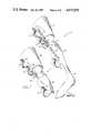
- a medial calf band subassembly 48Cextending from the posterior side around the medial side of the patient's calf;
- the sidebar portions 60 of the subassembliesare trimmed after curing to form a lug 60A (corresponding to the lug 24 of FIG. 1), or a clevis 60B (corresponding to the clevis 18 of FIG. 1).
- a clevisFor prefabricating a clevis, the two innermost layers 54 and 55 of the sidebar portion 60 are separated (spaced-apart) prior to the aforementioned curing thereof, either by a removeable mandrel, by inserting a suitable wedgelike plug made of prepreg plies, or a translucent material such as PLEXIGLAS®.
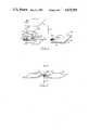
- FIG. 5shows the steps A-E for fabricating a drop lock ring in-situ.
- a first step Athe clevis 60B and the lug 60A are aligned in the stretched-out, or in-line, position.
- the clevisis wrapped with Teflon® tape 66 in an area that overlaps the lug.
- preimpregnated composite tape 68 of suitable material and dimensionis wrapped about the Teflon® tape 66 a sufficient number of turns to provide the required drop lock ring thickness.
- the lug and clevis of the medial thigh and calf subassemblies 48A,48C, and similarly the lug and clevis of the lateral thigh and calf subassemblies 48B,48Dare assembled with bushings 62, and are placed in a kit.
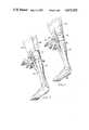
- FIG. 6shows a patient's leg 70 fitted with a joint fixture 72 in preparation for fitting the knee orthosis 32 of this invention.
- the joint fixture 72is essentially a U-shaped bracket having the following elements:
Landscapes
- Health & Medical Sciences (AREA)
- Nursing (AREA)
- Orthopedic Medicine & Surgery (AREA)
- Engineering & Computer Science (AREA)
- Biomedical Technology (AREA)
- Heart & Thoracic Surgery (AREA)
- Vascular Medicine (AREA)
- Life Sciences & Earth Sciences (AREA)
- Animal Behavior & Ethology (AREA)
- General Health & Medical Sciences (AREA)
- Public Health (AREA)
- Veterinary Medicine (AREA)
- Orthopedics, Nursing, And Contraception (AREA)
Abstract
Description
Claims (7)
Priority Applications (1)
| Application Number | Priority Date | Filing Date | Title |
|---|---|---|---|
| US06/869,522US4672955A (en) | 1986-06-02 | 1986-06-02 | Orthosis, method of making and kit therefor |
Applications Claiming Priority (1)
| Application Number | Priority Date | Filing Date | Title |
|---|---|---|---|
| US06/869,522US4672955A (en) | 1986-06-02 | 1986-06-02 | Orthosis, method of making and kit therefor |
Publications (1)
| Publication Number | Publication Date |
|---|---|
| US4672955Atrue US4672955A (en) | 1987-06-16 |
Family
ID=25353702
Family Applications (1)
| Application Number | Title | Priority Date | Filing Date |
|---|---|---|---|
| US06/869,522Expired - Fee RelatedUS4672955A (en) | 1986-06-02 | 1986-06-02 | Orthosis, method of making and kit therefor |
Country Status (1)
| Country | Link |
|---|---|
| US (1) | US4672955A (en) |
Cited By (24)
| Publication number | Priority date | Publication date | Assignee | Title |
|---|---|---|---|---|
| EP0486241A1 (en)* | 1990-11-13 | 1992-05-20 | Minnesota Mining And Manufacturing Company | Off-the-shelf custom knee brace |
| US5344390A (en)* | 1992-09-16 | 1994-09-06 | Motloch & Peterson | Body-worn orthopedic device that includes individual connected modules |
| US5372145A (en)* | 1992-09-16 | 1994-12-13 | Berger; J. Lee | Surgical hand support apparatus |
| US5425700A (en)* | 1994-02-18 | 1995-06-20 | Omni Scientific | Gravity operated orthotic brace drop lock |
| WO1996020659A1 (en)* | 1995-01-03 | 1996-07-11 | Smith & Nephew Donjoy Inc. | Orthopaedic brace having one-piece cuff |
| US5547463A (en)* | 1994-10-07 | 1996-08-20 | United States Surgical Corporation | Surgical hand support apparatus |
| US5681267A (en)* | 1995-04-10 | 1997-10-28 | Molino; Joseph L. | Arrangement for joining/separating distal orthotic device to/from pelvic interface |
| US5693007A (en)* | 1996-02-21 | 1997-12-02 | Townsend Design | Pre-assembled custom fit knee orthosis and method of making same |
| US5881730A (en)* | 1992-09-16 | 1999-03-16 | Burger; J. Lee | Surgical hand support apparatus |
| US6517505B1 (en) | 1999-10-26 | 2003-02-11 | Bernie T. Veldman | Pliable orthotic device |
| US6692453B2 (en) | 2001-10-22 | 2004-02-17 | Board Of Regents, University Of Nebraska Medical Center | Two piece wrist-hand-finger orthosis |
| US7311866B1 (en)* | 2002-06-25 | 2007-12-25 | Ebi, L.P. | Method for creating a mold for a knee brace and a knee brace |
| WO2008092443A1 (en)* | 2007-01-31 | 2008-08-07 | Otto Bock Healthcare Gmbh | Method for producing an orthesis |
| US20080300525A1 (en)* | 2007-06-04 | 2008-12-04 | Yaad Advanced Orthopedics Ltd | Ankle Foot Orthosis Device |
| US20090198166A1 (en)* | 2007-06-04 | 2009-08-06 | Ya'ad Advanced Orthopedics Ltd. | Ankle Foot Orthosis |
| US20100130946A1 (en)* | 2008-11-25 | 2010-05-27 | Geraldine Price Medley | Heel cap for skin treatment |
| US8882690B2 (en) | 2010-11-16 | 2014-11-11 | Fred W. Toenges | Orthotic device and method of manufacture |
| WO2019175589A1 (en)* | 2018-03-14 | 2019-09-19 | Orthotic Composites Limited | Medical device |
| US10814571B2 (en) | 2016-04-14 | 2020-10-27 | Becker Orthopedic Appliance Company | Curable, conformable composite precursors, conformable core structures, resulting products and methods |
| US10874539B2 (en) | 2017-05-05 | 2020-12-29 | Becker Orthopedic Appliance Company | Configurable orthosis and method of definitive orthotic design, fabrication and validation |
| WO2021173686A1 (en)* | 2020-02-24 | 2021-09-02 | Arctic Bracing, LLC | Orthopedic brace with custom-fitted framework of light-curable material |
| US11273060B2 (en) | 2005-03-31 | 2022-03-15 | Massachusetts Institute Of Technology | Artificial ankle-foot system with spring, variable-damping, and series-elastic actuator components |
| US11278433B2 (en)* | 2005-03-31 | 2022-03-22 | Massachusetts Institute Of Technology | Powered ankle-foot prosthesis |
| US11491032B2 (en) | 2005-03-31 | 2022-11-08 | Massachusetts Institute Of Technology | Artificial joints using agonist-antagonist actuators |
Citations (5)
| Publication number | Priority date | Publication date | Assignee | Title |
|---|---|---|---|---|
| CA870150A (en)* | 1971-05-04 | Solar Laboratories | Method and application of orthopedic appliances with an ultraviolet curable plastic impregnated bandage | |
| US4553535A (en)* | 1983-09-07 | 1985-11-19 | Alan Finnieston | Thigh brace |
| US4565190A (en)* | 1984-07-13 | 1986-01-21 | Northwestern University | Knee orthosis with swivel-action supracondular cuff |
| US4572167A (en)* | 1981-03-25 | 1986-02-25 | Sumner Brunswick | Orthopedic device and process |
| US4572169A (en)* | 1984-04-03 | 1986-02-25 | Kenneth D. Driver | Removable lower leg brace |
- 1986
- 1986-06-02USUS06/869,522patent/US4672955A/ennot_activeExpired - Fee Related
Patent Citations (5)
| Publication number | Priority date | Publication date | Assignee | Title |
|---|---|---|---|---|
| CA870150A (en)* | 1971-05-04 | Solar Laboratories | Method and application of orthopedic appliances with an ultraviolet curable plastic impregnated bandage | |
| US4572167A (en)* | 1981-03-25 | 1986-02-25 | Sumner Brunswick | Orthopedic device and process |
| US4553535A (en)* | 1983-09-07 | 1985-11-19 | Alan Finnieston | Thigh brace |
| US4572169A (en)* | 1984-04-03 | 1986-02-25 | Kenneth D. Driver | Removable lower leg brace |
| US4565190A (en)* | 1984-07-13 | 1986-01-21 | Northwestern University | Knee orthosis with swivel-action supracondular cuff |
Non-Patent Citations (22)
| Title |
|---|
| "Carbon Fibre Reinforced Plastic Applied to Prosthetics and Orthotics", Nelham, J. Biomed. Engng. 1981, vol. 3, Oct., pp. 305-314. |
| "Knee-Ankle-Foot Orthosis", United States Manufacturing Company, 1 page. |
| "Mold-A-Brace", C. H. Martin Company, 4 pages. |
| "PSSI Ankle Stabilizer", Physical Support Systems, Inc., 1 page. |
| "Scott-Craig™ Paraplegic Orthoses", Scott Orthotic Labs, 4 pages. |
| "Spiral Ankle-Foot Orthosis (AFO)", RTC, 2 pages. |
| "The ACL Dilemma", Townsend Industries, Inc., 13 pages. |
| "The Genucentric Knee Orthosis-A New Concept", R. Foster, J. Milani, Orthotics and Prosthetics, vol. 33, No. 2, pp. 31-44, Jun. 1979. |
| "The Only Self Molding Immediate Fit Orthotic", Dr. A. Blomer, 14 pages. |
| "Warm'n Form", Thermo Mold Medical Products, Inc.--brochure, 6 pages, 1974. |
| Carbon Fibre Reinforced Plastic Applied to Prosthetics and Orthotics , Nelham, J. Biomed. Engng. 1981, vol. 3, Oct., pp. 305 314.* |
| Dobi Symplex, Inc., Winter Park, Fla. (Catalogue complete).* |
| Dobi-Symplex, Inc., Winter Park, Fla. (Catalogue-complete). |
| Knee Ankle Foot Orthosis , United States Manufacturing Company, 1 page.* |
| Mold A Brace , C. H. Martin Company, 4 pages.* |
| PSSI Ankle Stabilizer , Physical Support Systems, Inc., 1 page.* |
| Scott Craig Paraplegic Orthoses , Scott Orthotic Labs, 4 pages.* |
| Spiral Ankle Foot Orthosis (AFO) , RTC, 2 pages.* |
| The ACL Dilemma , Townsend Industries, Inc., 13 pages.* |
| The Genucentric Knee Orthosis A New Concept , R. Foster, J. Milani, Orthotics and Prosthetics, vol. 33, No. 2, pp. 31 44, Jun. 1979.* |
| The Only Self Molding Immediate Fit Orthotic , Dr. A. Blomer, 14 pages.* |
| Warm n Form , Thermo Mold Medical Products, Inc. brochure, 6 pages, 1974.* |
Cited By (37)
| Publication number | Priority date | Publication date | Assignee | Title |
|---|---|---|---|---|
| EP0486241A1 (en)* | 1990-11-13 | 1992-05-20 | Minnesota Mining And Manufacturing Company | Off-the-shelf custom knee brace |
| US5344390A (en)* | 1992-09-16 | 1994-09-06 | Motloch & Peterson | Body-worn orthopedic device that includes individual connected modules |
| US5372145A (en)* | 1992-09-16 | 1994-12-13 | Berger; J. Lee | Surgical hand support apparatus |
| US5881730A (en)* | 1992-09-16 | 1999-03-16 | Burger; J. Lee | Surgical hand support apparatus |
| US5425700A (en)* | 1994-02-18 | 1995-06-20 | Omni Scientific | Gravity operated orthotic brace drop lock |
| US5813977A (en)* | 1994-10-07 | 1998-09-29 | United States Surgical Corporation | Surgical hand support apparatus |
| US5547463A (en)* | 1994-10-07 | 1996-08-20 | United States Surgical Corporation | Surgical hand support apparatus |
| WO1996020659A1 (en)* | 1995-01-03 | 1996-07-11 | Smith & Nephew Donjoy Inc. | Orthopaedic brace having one-piece cuff |
| US6110137A (en)* | 1995-01-03 | 2000-08-29 | Dj Orthopedics, Llc | Orthopaedic brace having one-piece cuff |
| US5681267A (en)* | 1995-04-10 | 1997-10-28 | Molino; Joseph L. | Arrangement for joining/separating distal orthotic device to/from pelvic interface |
| EP0791346A3 (en)* | 1996-02-21 | 1997-12-29 | Townsend Industries, Inc. | Pre-assembled custom fit knee orthosis and method of making same |
| US5693007A (en)* | 1996-02-21 | 1997-12-02 | Townsend Design | Pre-assembled custom fit knee orthosis and method of making same |
| US6517505B1 (en) | 1999-10-26 | 2003-02-11 | Bernie T. Veldman | Pliable orthotic device |
| US6692453B2 (en) | 2001-10-22 | 2004-02-17 | Board Of Regents, University Of Nebraska Medical Center | Two piece wrist-hand-finger orthosis |
| US7311866B1 (en)* | 2002-06-25 | 2007-12-25 | Ebi, L.P. | Method for creating a mold for a knee brace and a knee brace |
| US20080105994A1 (en)* | 2002-06-25 | 2008-05-08 | Ebi, L.P. | Method for creating a mold for a knee brace and a knee brace |
| US8123993B2 (en) | 2002-06-25 | 2012-02-28 | Ebi, Llc | Method for creating a mold for a knee brace and a knee brace |
| US11278433B2 (en)* | 2005-03-31 | 2022-03-22 | Massachusetts Institute Of Technology | Powered ankle-foot prosthesis |
| US11491032B2 (en) | 2005-03-31 | 2022-11-08 | Massachusetts Institute Of Technology | Artificial joints using agonist-antagonist actuators |
| US11273060B2 (en) | 2005-03-31 | 2022-03-15 | Massachusetts Institute Of Technology | Artificial ankle-foot system with spring, variable-damping, and series-elastic actuator components |
| US8673199B2 (en)* | 2007-01-31 | 2014-03-18 | Otto Bock Healthcare Gmbh | Method for producing an orthesis |
| US20100186885A1 (en)* | 2007-01-31 | 2010-07-29 | Michael Ottleben | Method for producing an orthesis |
| US20110232837A9 (en)* | 2007-01-31 | 2011-09-29 | Michael Ottleben | Method for producing an orthesis |
| WO2008092443A1 (en)* | 2007-01-31 | 2008-08-07 | Otto Bock Healthcare Gmbh | Method for producing an orthesis |
| CN101600405B (en)* | 2007-01-31 | 2012-09-05 | 奥托·博克保健有限公司 | Method for producing an orthesis |
| US20090198166A1 (en)* | 2007-06-04 | 2009-08-06 | Ya'ad Advanced Orthopedics Ltd. | Ankle Foot Orthosis |
| US8323224B2 (en) | 2007-06-04 | 2012-12-04 | Ya'ad Advanced Orthopedics Ltd. | Ankle foot orthosis |
| US20080300525A1 (en)* | 2007-06-04 | 2008-12-04 | Yaad Advanced Orthopedics Ltd | Ankle Foot Orthosis Device |
| US20100130946A1 (en)* | 2008-11-25 | 2010-05-27 | Geraldine Price Medley | Heel cap for skin treatment |
| US8882690B2 (en) | 2010-11-16 | 2014-11-11 | Fred W. Toenges | Orthotic device and method of manufacture |
| US10814571B2 (en) | 2016-04-14 | 2020-10-27 | Becker Orthopedic Appliance Company | Curable, conformable composite precursors, conformable core structures, resulting products and methods |
| US10874539B2 (en) | 2017-05-05 | 2020-12-29 | Becker Orthopedic Appliance Company | Configurable orthosis and method of definitive orthotic design, fabrication and validation |
| US11786391B2 (en) | 2017-05-05 | 2023-10-17 | Becker Orthopedic Appliance Company | Configurable orthosis and method of definitive orthotic design, fabrication and validation |
| WO2019175589A1 (en)* | 2018-03-14 | 2019-09-19 | Orthotic Composites Limited | Medical device |
| WO2021173686A1 (en)* | 2020-02-24 | 2021-09-02 | Arctic Bracing, LLC | Orthopedic brace with custom-fitted framework of light-curable material |
| US20230148303A1 (en)* | 2020-02-24 | 2023-05-11 | Arctic Bracing Llc | Orthopedic brace with custom-fitted framework of light-curable material |
| EP4110243A4 (en)* | 2020-02-24 | 2024-06-05 | Arctic Bracing, LLC | ORTHOPEDIC SUPPORT WITH INDIVIDUALLY ADAPTED FRAME MADE OF LIGHT-CURING MATERIAL |
Similar Documents
| Publication | Publication Date | Title |
|---|---|---|
| US4672955A (en) | Orthosis, method of making and kit therefor | |
| US5897515A (en) | Ankle-foot orthosis | |
| DE60315698T2 (en) | FUßGELENKORTHOSE | |
| US9554923B2 (en) | Prosthesis socket and system comprising a prosthesis socket and prosthesis device | |
| US8591446B2 (en) | Ortho training device | |
| DE69719374T2 (en) | BOOTS FOR AN ORTHOPEDIC ASSOCIATION | |
| US5312669A (en) | Thermoplastic composite reinforcement and method for orthotic, prosthetic and other devices | |
| EP0269946B1 (en) | Ankle joint support | |
| US8465445B2 (en) | Ankle and foot orthosis | |
| DE69004768T2 (en) | Stroller support. | |
| US6059834A (en) | Suspended/orthopaedic sleeves with internal adhesive to prevent sleeve migration | |
| DE69820214T2 (en) | Adjustable foot and ankle orthosis | |
| US20060270958A1 (en) | Ankle and foot orthosis | |
| US20050187505A1 (en) | Spherical joint orthosis | |
| KR20030090748A (en) | Ankle-foot orthosis | |
| US9295575B1 (en) | Braided orthotic products and methods of manufacture | |
| US5382223A (en) | Contoured orthopaedic support having reduced skin irritation properties | |
| GB2571965A (en) | Medical device | |
| US7749423B2 (en) | Method of producing an orthotic brace or prosthetic device | |
| US20150011924A1 (en) | Carbon fiber orthosis and associated method | |
| EP1227774B1 (en) | Ankle/foot orthosis | |
| US12042414B2 (en) | Splint device | |
| WO1995031950A1 (en) | Prefabricated orthosis of composite material | |
| US10376390B1 (en) | Prosthetic limb kit and method of manufacture | |
| Nelham | Carbon fibre reinforced plastic applied to prosthetics and orthotics |
Legal Events
| Date | Code | Title | Description |
|---|---|---|---|
| AS | Assignment | Owner name:UNITED TECHNOLOGIES CORPORATION, HARTFORD, CONNECT Free format text:ASSIGNMENT OF ASSIGNORS INTEREST.;ASSIGNOR:COOPER, ADRIAAN;REEL/FRAME:004561/0514 Effective date:19860523 Owner name:UNITED TECHNOLOGIES CORPORATION, CONNECTICUT Free format text:ASSIGNMENT OF ASSIGNORS INTEREST;ASSIGNOR:COOPER, ADRIAAN;REEL/FRAME:004561/0514 Effective date:19860523 | |
| FEPP | Fee payment procedure | Free format text:PAYOR NUMBER ASSIGNED (ORIGINAL EVENT CODE: ASPN); ENTITY STATUS OF PATENT OWNER: LARGE ENTITY | |
| FPAY | Fee payment | Year of fee payment:4 | |
| FEPP | Fee payment procedure | Free format text:PAYOR NUMBER ASSIGNED (ORIGINAL EVENT CODE: ASPN); ENTITY STATUS OF PATENT OWNER: LARGE ENTITY Free format text:PAYER NUMBER DE-ASSIGNED (ORIGINAL EVENT CODE: RMPN); ENTITY STATUS OF PATENT OWNER: LARGE ENTITY | |
| FPAY | Fee payment | Year of fee payment:8 | |
| REMI | Maintenance fee reminder mailed | ||
| LAPS | Lapse for failure to pay maintenance fees | ||
| FP | Lapsed due to failure to pay maintenance fee | Effective date:19990616 | |
| STCH | Information on status: patent discontinuation | Free format text:PATENT EXPIRED DUE TO NONPAYMENT OF MAINTENANCE FEES UNDER 37 CFR 1.362 |