US4672366A - Subterranean tank leak containment and detection system - Google Patents
Subterranean tank leak containment and detection systemDownload PDFInfo
- Publication number
- US4672366A US4672366AUS06/792,737US79273785AUS4672366AUS 4672366 AUS4672366 AUS 4672366AUS 79273785 AUS79273785 AUS 79273785AUS 4672366 AUS4672366 AUS 4672366A
- Authority
- US
- United States
- Prior art keywords
- tank
- leak
- enclosure
- body sheet
- leakage
- Prior art date
- Legal status (The legal status is an assumption and is not a legal conclusion. Google has not performed a legal analysis and makes no representation as to the accuracy of the status listed.)
- Expired - Fee Related
Links
- 238000001514detection methodMethods0.000titleclaimsabstractdescription36
- 229920001903high density polyethylenePolymers0.000claimsabstractdescription24
- 239000004700high-density polyethyleneSubstances0.000claimsabstractdescription24
- 239000003209petroleum derivativeSubstances0.000claimsabstractdescription19
- 238000000034methodMethods0.000claimsdescription14
- 238000005260corrosionMethods0.000claimsdescription13
- 230000007797corrosionEffects0.000claimsdescription13
- 229910000831SteelInorganic materials0.000claimsdescription11
- 239000004020conductorSubstances0.000claimsdescription11
- 239000010959steelSubstances0.000claimsdescription11
- 230000015556catabolic processEffects0.000claimsdescription9
- 238000006731degradation reactionMethods0.000claimsdescription9
- 239000000126substanceSubstances0.000claimsdescription8
- 239000004746geotextileSubstances0.000claimsdescription7
- 238000009413insulationMethods0.000claimsdescription7
- 239000003502gasolineSubstances0.000claimsdescription6
- 238000007789sealingMethods0.000claimsdescription6
- 238000010438heat treatmentMethods0.000claimsdescription4
- 239000007788liquidSubstances0.000claimsdescription4
- 238000012544monitoring processMethods0.000claimsdescription3
- 239000003208petroleumSubstances0.000claims5
- 239000003112inhibitorSubstances0.000claims3
- 239000000463materialSubstances0.000abstractdescription8
- 229920004889linear high-density polyethylenePolymers0.000abstractdescription3
- 230000002745absorbentEffects0.000abstractdescription2
- 239000002250absorbentSubstances0.000abstractdescription2
- 238000009434installationMethods0.000description8
- 230000008901benefitEffects0.000description6
- 238000004210cathodic protectionMethods0.000description6
- 239000000945fillerSubstances0.000description6
- 239000000446fuelSubstances0.000description6
- 238000009412basement excavationMethods0.000description5
- 238000011109contaminationMethods0.000description5
- XLYOFNOQVPJJNP-UHFFFAOYSA-NwaterSubstancesOXLYOFNOQVPJJNP-UHFFFAOYSA-N0.000description5
- 239000003673groundwaterSubstances0.000description4
- 239000002689soilSubstances0.000description4
- 238000003466weldingMethods0.000description4
- 239000006096absorbing agentSubstances0.000description3
- 239000003921oilSubstances0.000description3
- 239000004927claySubstances0.000description2
- 231100001010corrosiveToxicity0.000description2
- 239000003599detergentSubstances0.000description2
- 230000008439repair processEffects0.000description2
- 230000000717retained effectEffects0.000description2
- XUIMIQQOPSSXEZ-UHFFFAOYSA-NSiliconChemical compound[Si]XUIMIQQOPSSXEZ-UHFFFAOYSA-N0.000description1
- 239000002253acidSubstances0.000description1
- 150000007513acidsChemical class0.000description1
- 230000015572biosynthetic processEffects0.000description1
- 238000009933burialMethods0.000description1
- 239000003518causticsSubstances0.000description1
- 230000006378damageEffects0.000description1
- 230000000694effectsEffects0.000description1
- 238000004880explosionMethods0.000description1
- 239000004744fabricSubstances0.000description1
- 239000011152fibreglassSubstances0.000description1
- 239000012530fluidSubstances0.000description1
- 238000011010flushing procedureMethods0.000description1
- 238000005755formation reactionMethods0.000description1
- 239000002828fuel tankSubstances0.000description1
- 239000004519greaseSubstances0.000description1
- 239000012774insulation materialSubstances0.000description1
- 239000012212insulatorSubstances0.000description1
- 230000007246mechanismEffects0.000description1
- 239000003348petrochemical agentSubstances0.000description1
- 238000004023plastic weldingMethods0.000description1
- 230000002028prematureEffects0.000description1
- 238000003825pressingMethods0.000description1
- 230000008569processEffects0.000description1
- 230000001681protective effectEffects0.000description1
- 238000009420retrofittingMethods0.000description1
- 230000000630rising effectEffects0.000description1
- 239000004576sandSubstances0.000description1
- 229910052710siliconInorganic materials0.000description1
- 239000010703siliconSubstances0.000description1
- 239000002904solventSubstances0.000description1
Images


Classifications
- G—PHYSICS
- G01—MEASURING; TESTING
- G01M—TESTING STATIC OR DYNAMIC BALANCE OF MACHINES OR STRUCTURES; TESTING OF STRUCTURES OR APPARATUS, NOT OTHERWISE PROVIDED FOR
- G01M3/00—Investigating fluid-tightness of structures
- G01M3/02—Investigating fluid-tightness of structures by using fluid or vacuum
- G01M3/04—Investigating fluid-tightness of structures by using fluid or vacuum by detecting the presence of fluid at the leakage point
- G01M3/042—Investigating fluid-tightness of structures by using fluid or vacuum by detecting the presence of fluid at the leakage point by using materials which expand, contract, disintegrate, or decompose in contact with a fluid
- G01M3/045—Investigating fluid-tightness of structures by using fluid or vacuum by detecting the presence of fluid at the leakage point by using materials which expand, contract, disintegrate, or decompose in contact with a fluid with electrical detection means
- B—PERFORMING OPERATIONS; TRANSPORTING
- B65—CONVEYING; PACKING; STORING; HANDLING THIN OR FILAMENTARY MATERIAL
- B65D—CONTAINERS FOR STORAGE OR TRANSPORT OF ARTICLES OR MATERIALS, e.g. BAGS, BARRELS, BOTTLES, BOXES, CANS, CARTONS, CRATES, DRUMS, JARS, TANKS, HOPPERS, FORWARDING CONTAINERS; ACCESSORIES, CLOSURES, OR FITTINGS THEREFOR; PACKAGING ELEMENTS; PACKAGES
- B65D90/00—Component parts, details or accessories for large containers
- B65D90/48—Arrangements of indicating or measuring devices
- B65D90/50—Arrangements of indicating or measuring devices of leakage-indicating devices
- B65D90/501—Arrangements of indicating or measuring devices of leakage-indicating devices comprising hollow spaces within walls
- B65D90/503—Arrangements of indicating or measuring devices of leakage-indicating devices comprising hollow spaces within walls under pressure or vacuum
- G—PHYSICS
- G01—MEASURING; TESTING
- G01M—TESTING STATIC OR DYNAMIC BALANCE OF MACHINES OR STRUCTURES; TESTING OF STRUCTURES OR APPARATUS, NOT OTHERWISE PROVIDED FOR
- G01M3/00—Investigating fluid-tightness of structures
- G01M3/02—Investigating fluid-tightness of structures by using fluid or vacuum
- G01M3/04—Investigating fluid-tightness of structures by using fluid or vacuum by detecting the presence of fluid at the leakage point
- G01M3/16—Investigating fluid-tightness of structures by using fluid or vacuum by detecting the presence of fluid at the leakage point using electric detection means
- G01M3/18—Investigating fluid-tightness of structures by using fluid or vacuum by detecting the presence of fluid at the leakage point using electric detection means for pipes, cables or tubes; for pipe joints or seals; for valves; for welds; for containers, e.g. radiators
- G01M3/186—Investigating fluid-tightness of structures by using fluid or vacuum by detecting the presence of fluid at the leakage point using electric detection means for pipes, cables or tubes; for pipe joints or seals; for valves; for welds; for containers, e.g. radiators for containers, e.g. radiators
Definitions
- the present inventionrelates to the field of leak containment and detection, and is concerned with improvements in containment and detection of leaks from underground storage tanks, for example, tanks used for storage of gasoline or other petrochemicals.
- the present inventionprovides a method of containing and detecting leakage from a subterranean tank containing a petroleum product such as gasoline or heating oil, by providing adjacent the tank an electrical leak detecting cable of the type that has an insulator that is subject to degradation by the petroleum product, enclosing the cable and tank together in an enclosure impervious to the product, sealing the enclosure to prevent the ingress of the product due to accidental spillage or from other sources of the product, and connecting the cable to an electrical sensor whereby leakage from the tank into the sealed enclosure is detected by the cable and electrical sensor.
- a petroleum productsuch as gasoline or heating oil
- Leakagemay occur from underground storage tanks from a number of causes. Since most tanks are steel, internal and external corrosion resulting in perforation of the tank is probably the primary causes of leakage. Internal corrosion results from the presence of water or acids in the stored products. External corrosion is due to groundwater and other soil-borne corrosives. Leaks may also be caused by cracks or by punctures due to sharp stones, pressing on the tank wall. In extremely dry, porous soils punctures might occur in such a way as to prevent leakage from the tank reaching the leak detector. In order to prevent this, and to ensure that any leak from the tank reaches the leak sensor in a minimum time, the present invention provides two additional important features.
- a drainage mestis wrapped around the tank, inside the enclosures, and secondly, an absorbent geotextile is placed along the bottom of the tank. This latter material collects and hold leaking products so that it cannot escape to the enviroment without being detected.
- An acceptable form of drainage meshis sold by Tensar Corporation, Marrow Ga., as TENSAR drainage net.
- a suitable geotextile absorberis sold by American Engineering Fabrics Inc. 1 Coffin Avenue, New Bedford, Mass., 02746 U.S.A.
- the leak sensoris positioned in a perforated duct inside the enclosure adjacent the tank so that leakage from the tank will penetrate the duct, and be detected by the leak sensor.
- the perforated ductthus can be used to gain access to the leak detection cable.
- both ends of the cablemay extend outside the enclosure (in suitable protective sleeves), one end being connected to a suitable monitor, for example, the Total Containment Inc. model M105B, the other end being terminated by a fixed resistance.
- a suitable monitorfor example, the Total Containment Inc. model M105B
- the cablemay be replaced after destruction by leakage by using the destroyed cable to pull a new cable through the duct, after the source of leakage has been pinpointed and the leaking container repaired and resealed.
- the enclosuremay be cleansed using a flushing technique with detergents, to rehabilitate the interior of the enclosure, thus avoiding the necessity of excavation.
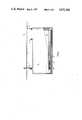
- FIG. 1is a vertical longitudinal section through a typical cylindrical subterranean tank protected in accordance with the present invention
- FIG. 2is a transverse vertical section of the tank of FIG. 1,
- FIG. 3is a detailed view of the filler pipe in FIG. 1,
- FIG. 4is a view partly in section of an alternative form of enclosure and leak detection system in accordance with the invention.
- FIG. 5is a detailed view on the line A--A of FIG. 4,
- FIG. 6is a perspective view illustrating the assembly of an alternate form of leak detection enclosure
- FIG. 7is a detailed view of the Pump Piping of FIG. 4,
- FIG. 8illustrates the application of cathodic protection to a tank
- FIG. 9is a perspective view illustrating the application of a preferred form of secondary containment to a fuel storage tank
- FIG. 10is a cross-section through a fuel tank with the secondary containment system in place.
- FIG. 1there is shown a tank 10 sealed within a secondary containment enclosure. Extending through the enclosure is a fill pipe 12 and a leak detection duct 13. Located within the duct 13 is a leak sensor cable 14 terminated with a resistor 15. The entire installation is below ground level 16.
- FIG. 3illustrates one way in which the enclosure 11 may be sealed to the filler pipe 12. As illustrated the enclosure 11 is drawn up around the filler pipe 12 to a point 19, and screw clamps 20 may be used together with a suitable sealer to complete the sealing of the enclosure 11 about the filler pipe 12. Clay might be added to completely isolate this whole section from contaminated ground.
- a principal advantageis that it is now possible to use a bare steel tank in an underground location without premature failure of the tank due to corrosion.
- Such bare steel tankis the least expensive container for storing fuels, but is not presently used because of leakage caused by corrosion.
- the tank 10 being entirely sealed in the enclosure 11is completely isolated from any of the corrosive effects due to its environment.
- One form of the enclosure material particularly suitable for use with the inventionis linear high density polyethylene (HDPE).
- Linear HDPEmay, of course, be welded with commercially available plastic welding tools, available for example from Munsch Chemiepumpen GmbH.
- the leak detection duct 13 used in FIG. 1 and FIG. 3can be formed for example from one inch diameter perforated HDPE pipe.
- the use of the duct containing the sensor cablealso provides a significant further feature for the invention since, should petroleum products for any unforesen reason other than by a leak get into the space between the tank and the enclosure, it is quite simple to circulate water with or without detergent added through the duct and flush out the product and replace the sensor cable.
- the system of the present inventionprovides a significant further advantage in the event of a leak in that the enclosure is capable of retaining the leak and avoiding unnecessary contamination of the surrounding environment.
- underground storage tankscan be maintained in a controlled environment free from moisture and harmful chemicals in the surrounding ground.
- corrosion of tankscan be kept to a minimum.
- a further advantage of the inventionis that in the event of a leak or sudden failure of the tank any product in the tank will not be lost to the environment where it is able to pollute the surrounding ground water.
- the enclosureretains all of the lost product within its walls so that it may be removed safely and without contamination of the product or of the surrounding area.
- the material used for the enclosure of the present inventionis strong, water and oil resistant.
- the enclosureis formed from three prefabricated sections; two end caps which are of the desired diameter with a six inch lip and one body sheet the same length as the tank, as wide as the circumference of the tank plus two feet.
- the enclosureis welded together on site using a commercially available HDPE welding process. In a typical installation, the site excavation is dug in the normal manner with a six inch layer of compacted sand placed on the bottom.
- the leak detection duct 13may be laid in the form of a letter L or preferably the letter U with the vertical end(s) rising to the ground level 16, while a horizontal run is along the bottom, right on the material of the enclosure.
- the enclosurecan be welded together. Prior to sealing it is also possible to add chemicals in the bottom of the enclosure to inhibit corrosion of the steel storage tank. When the top flaps are sealed, holes are cut for fill pipes, vent pipes and pump pipes. Special sleeves or “chimneys” may be made for these pipes and welded to the enclosure so that all connections are protected to the ground surface as illustrated in FIG. 3. These sleeves may be clamped with a screw clamp 20 approximately six inches below the ground level 16, filled with silicon grease and then sealed with a second clamp as illustrated in FIG. 3. Impervious clay can then be used to further isolate this area to prevent liquids from entering the bag.
- the enclosureAfter sealing the upper end of the top flap 17, the enclosure should be completely sealed so that no moisture is able to get into the liner where it is able to affect the tank 10.
- a man-hole(not shown) may be placed so that it will be slightly below final grade and not affected by any surface equipment such as snowplows or the like.
- a sensor cable 14is installed within the leak detection duct 13.
- a suitable form of cableis disclosed in Canadian Pat. No. 775,758 of Jan. 9, 1968 to E. O. Butts (corresponding to U.S. Pat. No. 3,564,526) and Canadian Pat. No. 978,614 of Nov. 25, 1975 to Wolkowski, contents of all of which are incorporated hereinto by reference.
- a twisted pair of conductorsare separated by insulation materials which are subject to degradation upon contact with petroleum products such as gasoline or heating oil. Sufficient degradation alters the resistance between conductors and ultimately allows the conductors to come into contact with each other and thereby energize an alarm.
- preassemble the enclosure, duct, sensor, and tankto factory seal the preassembled unit, which may then be installed in a suitable excavation, and connected to filler pipes and leak detection monitors.
- the tankis now in a moisture and chemical free controlled environment.
- Leaking tankscan be accurately identified.
- Old steel tankscan be reclaimed and used again since corrosion can now be controlled. This makes retrofitting older gas stations for example a feasible solution because their tanks will probably not require changing but can merely be excavated, fitted with an enclsoure, duct and sensor and reinstalled. Additionally, all fittings and piping are enclosed in the enclosure so that these can be monitored for leaks also.
- FIG. 4illustrates an alternative form of enclosure for use with a bare steel tank, particularly useful for example in the service station environment.
- the tank 30is enclosed in a linear HDPE enclosure consisting of a pair of molded end caps 31 and a body sheet 32.
- the end of the cylindrical tank 33is spaced from the inner end of the end cap 31, to provide a space for the applicant's preferred one inch perforated duct containing the leak detection cable 34.
- the leak detection cable and duct 34extend to the bottom edge of the tank to provide the earliest possible sensing of any leakage which may occur from within the tank.
- the duct 34is connected to a test point at the surface 35 by an impervious HDPE chimney fitting 36 welded to the end cap 31.
- the fill pipe 37 and vent pipe 38are both encased in HDPE chimney fittings similarly welded to the body sheet 32.
- the piping to pumps 39may be similarly protected with an appropriate chimney fitting of HDPE, and in addition in accordance with a further feature of the invention may be provided with leak detection cable for sensing leaks in the piping to the pumps which leak detection cable may be connected via a further impervious HDPE pipe 40 to the test point 35.
- the detail of the interconnection of the piping to pumps 39 and the pipe 40is illustrated in FIG. 7.
- FIG. 5illustrates a detail of the junction between the end cap 31 and the body sheet 32 at the point A--A of FIG. 4. As illustrated, the end cap 31 overlaps the body sheet 32 and is welded thereto with an HDPE weld at 41.
- the perforated duct 34 containing the sensor cable 42passes along the bottom edge of the end cap 31 such that any leakage from the tank 30 will contact the sensor cable 42 at the earliest opportunity, to give indication of such a leak.
- FIG. 6illustrates the assembly of the applicant's enclosure to a typcial gasoline storage tank.
- a typcial gasoline storage tankSuch tank 30 is equipped with lifting lugs 43 for lifting and positioning the tank.
- the body sheet 32is positioned in the excavation in which the tank 30 is to be installed, the tank is placed on the body sheet 32, and the ends of the sheet are then wrapped around the tank, appropriate slits 44 being provided to accommodate the lifting lugs 43.
- the body sheet 32is then welded to itself with the tank inside the sheet.
- the end caps 31 containing the perforated duct 34 and leak detection cable 42are mounted on the ends of the tank, and the end caps 31 are welded to the body sheet using known high density polyethylene welding techniques. Patches are welded over the lifting lugs. With the tank entirely sealed in the high density polyethylene container all leakage from the tank is completely prevented.
- a preferable material for use as the body sheet and end capsis linear high density polyethylene the thickness of the sheet material is at least 0.100 inch.
- the enclosure componentsmay be prefabricated to the tank dimensions and shipped to the tank manufacturer where the components are permanently attached to the tank to protect the tank during transportation. On site the tank may be pressure tested according to local requirements. If the enclosure is to be applied on site, the body sheet and end caps can be shipped as a kit and welded to the tank. The leak detection cable is fitted into the end fittings, and the entire enclosure is welded together on the tank prior to burial. The piping to the pumps, filler pipes and vent pipes can also be fitted with separate leak detection systems. Special chimney fittings are designed to fit over the tank piping and are clamped to the pipes with the bases welded to the enclosure so as to prevent liquids from entering the enclosure at these locations. All wiring connections are done after backfilling so as to allow the tanks and piping systems to be monitored by a single monitor.
- FIG. 7illustrates a detail of FIG. 4 in which a tank 30 sealed within a body sheet 32 is provided with a chimney fitting 45 also welded to the body sheet 32 through which piping to the fuel dispensing pumps is passed.
- the chimney fitting 45is clamped to the pipe 46 by a clamp 47, and a further HDPE sleeve 48 is fitted over the piping 46 and the chimney 45, and is clamped by a screw clamp 49 about the piping 46.
- a further leak detection cable 50 contained within a non-perforated duct 40is looped around the piping 46 just above the clamp 49, to provide a mechanism for detecting leaks in the piping 46 which might otherwise go undetected, or which, if clamps 47 and 49 were not provided on the piping 46, leak back into the enclosure to give an erroneous detection of a leak in the tank per se.
- FIG. 8illustrates the application of cathodic protection to a tank positioned in an enclosure in accordance with the invention.
- the tank 30is provided with a standard cathodic protection cable 62 welded at 61 to the tank 30.
- the other end of cable 62is attached to a bag of chemicals 64.
- the cable 62is fed through the HDPE pipe 36 together with the leak detection cable 34.
- the chemical bag 64is buried in the ground and acts as a sacrificial anode in the usual way.
- the system of the present inventionspecifically lends itself to replacement of the sensor cable without any excavation, and the system can be filled with water, causing the petroleum product to float out through the test point.
- the watermay be pumped out from the system, and a new cable installed and the system reactivated. This technique is particularly attractive in the case of large tanks, which are frequently repaired from the inside for example by re-welding previously cracked welds, or welding plates over leak locations.
- FIGS. 9 and 10illustrate a preferred form of secondary containment system of the present invention.
- a cylindrical tank 30, preferably without lifting lugs,is wrapped in a body sheet 32 of HDPE the sheet 32 is rectangular when flat and is of sufficient width and length to completely cover the tank except for the ends. As before the sheet 32 is wrapped around the tank and welded in place.
- Between the tank 30 and the body sheet 32are a geotextile absorber 120 and a drainage mesh 121.
- the mesh 121provides channels for the flow of leakage from the tank 30 to the absorber 120 which ensures that any leakage is retained in the vicinity of the leak sensor located in one of the end caps 122.
- the end caps 122 and 123are welded to the body sheet to complete the secondary containment system.
- the interior surface of the body sheetcould be suitably ribbed to provide the required flow channels.
- the tankshould be installed with the end containing the leak sensor lower than the other end, to assist in early detection of leakage.
- One of the end caps 122is provided with a perforated tube or well in which the leak sensor may be located.
Landscapes
- Physics & Mathematics (AREA)
- General Physics & Mathematics (AREA)
- Engineering & Computer Science (AREA)
- Mechanical Engineering (AREA)
- Examining Or Testing Airtightness (AREA)
Abstract
Description
Claims (13)
Priority Applications (6)
| Application Number | Priority Date | Filing Date | Title |
|---|---|---|---|
| CA000521160ACA1316579C (en) | 1985-10-29 | 1986-10-22 | Subterranean tank leak containment and detection system and method |
| JP61253881AJPS62182091A (en) | 1985-10-29 | 1986-10-27 | Method and system of detecting and inhibiting leakage of petroleum product from underground tank |
| PL86262106APL161650B1 (en) | 1985-10-29 | 1986-10-29 | Protecting system for an underground liquid product storage tank |
| DE8686115040TDE3686389T2 (en) | 1985-10-29 | 1986-10-29 | DEVICE FOR LEAK DETECTION AND LEAK MONITORING FOR UNDERGROUND CONTAINERS. |
| NO864327ANO172819C (en) | 1985-10-29 | 1986-10-29 | SECONDARY BARRIER FOR AN UNDERGROUND STOCK TANK |
| EP86115040AEP0220730B1 (en) | 1985-10-29 | 1986-10-29 | Subterranean tank leak containment and detection system |
Applications Claiming Priority (2)
| Application Number | Priority Date | Filing Date | Title |
|---|---|---|---|
| CA000368169ACA1120131A (en) | 1981-01-09 | 1981-01-09 | Subterranean tank leak detection system and method |
| CA368169 | 1981-01-09 |
Related Parent Applications (1)
| Application Number | Title | Priority Date | Filing Date |
|---|---|---|---|
| US06/514,615Continuation-In-PartUS4568925A (en) | 1981-01-09 | 1983-07-18 | Subterranean tank leak detection system and method |
Publications (1)
| Publication Number | Publication Date |
|---|---|
| US4672366Atrue US4672366A (en) | 1987-06-09 |
Family
ID=4118869
Family Applications (2)
| Application Number | Title | Priority Date | Filing Date |
|---|---|---|---|
| US06/514,615Expired - LifetimeUS4568925A (en) | 1981-01-09 | 1983-07-18 | Subterranean tank leak detection system and method |
| US06/792,737Expired - Fee RelatedUS4672366A (en) | 1981-01-09 | 1985-10-29 | Subterranean tank leak containment and detection system |
Family Applications Before (1)
| Application Number | Title | Priority Date | Filing Date |
|---|---|---|---|
| US06/514,615Expired - LifetimeUS4568925A (en) | 1981-01-09 | 1983-07-18 | Subterranean tank leak detection system and method |
Country Status (4)
| Country | Link |
|---|---|
| US (2) | US4568925A (en) |
| EP (1) | EP0057973A1 (en) |
| JP (1) | JPS57136134A (en) |
| CA (1) | CA1120131A (en) |
Cited By (37)
| Publication number | Priority date | Publication date | Assignee | Title |
|---|---|---|---|---|
| US4796676A (en)* | 1987-06-05 | 1989-01-10 | Hendershot John A | Fluid storage tank system |
| US4798496A (en)* | 1987-02-10 | 1989-01-17 | Nippon Engineer Service Kabushiki Kaisha | Underground tank with leak detection mechanism |
| EP0220730A3 (en)* | 1985-10-29 | 1989-04-05 | Total Containment International, Inc. | Subterranean tank leak containment and detection system and method |
| US4905501A (en)* | 1987-12-24 | 1990-03-06 | Kabushiki Kaisha Nippon Automation | Jig for leak check |
| US4916939A (en)* | 1986-11-28 | 1990-04-17 | Moegel Helmut | Protective lining arrangement |
| US4922232A (en)* | 1988-10-21 | 1990-05-01 | Bosich Joseph F | Leakage containment and detection systems |
| US4973946A (en)* | 1989-03-09 | 1990-11-27 | Cowden Ii Roger H | Underground liquid storage tank leak containment, detection and alarm system |
| US5036287A (en)* | 1989-02-17 | 1991-07-30 | Dipl.-Ing. Wrede & Niedecken Verwaltung Gmbh | Procedure and device for corrosion determination |
| US5072623A (en)* | 1991-06-25 | 1991-12-17 | World Enviro Systems, Inc. | Double bladder fluid containment system |
| US5174150A (en)* | 1991-10-29 | 1992-12-29 | In-Situ, Inc. | Device and method for reducing false indications of leakage in a double-wall tank |
| US5269173A (en)* | 1990-05-11 | 1993-12-14 | Klaus Henneck | Flat bottomed tanks and process to detect leakages |
| US5400646A (en)* | 1992-09-30 | 1995-03-28 | Mepco, Inc. | Fluid containment monitoring system |
| WO1995032026A1 (en)* | 1994-05-20 | 1995-11-30 | Stir-Melter, Inc. | Apparatus and method for vitrifying hazardous waste |
| WO1995032025A1 (en)* | 1994-05-20 | 1995-11-30 | Stir-Melter, Inc. | Apparatus and method for vitrification of hazardous waste |
| WO1997002991A1 (en)* | 1995-07-12 | 1997-01-30 | Rudolph Caparros | Containment and delivery apparatus for hazardous fluids |
| EP0764596A1 (en) | 1995-09-20 | 1997-03-26 | WALTER TOSTO SERBATOI S.p.A. | An outer protection and secondary containment system for an underground metal tank for liquid hydrocarbons and a structural element thereof |
| US5711635A (en)* | 1994-05-20 | 1998-01-27 | Stir-Melter, Inc. | Apparatus for hazardous waste vitrification |
| US5863152A (en)* | 1996-02-01 | 1999-01-26 | Ingalls; Peter Wayne | Mechanical gas vent |
| KR100315080B1 (en)* | 1999-07-14 | 2001-11-26 | 김수환 | An oil tank laid under the ground |
| US20030054309A1 (en)* | 2001-08-24 | 2003-03-20 | King Joseph Henry | Oil tank thermal stability system |
| US20040045343A1 (en)* | 2002-09-10 | 2004-03-11 | Hutchinson Ray J. | Secondary containment system and method |
| US20040149017A1 (en)* | 2002-09-10 | 2004-08-05 | Hutchinson Ray J. | Secondary containment leak prevention and detection system and method |
| US20040154380A1 (en)* | 2001-04-26 | 2004-08-12 | Walker Ian C. | Method and apparatus for leak detection and location |
| US20040182136A1 (en)* | 2003-03-17 | 2004-09-23 | Don Halla | Fuel storage tank leak prevention and detection system and method |
| US20040200525A1 (en)* | 2003-04-11 | 2004-10-14 | Goodson H. Dean | Thread protection system with weather barrier |
| US20040201131A1 (en)* | 2003-04-11 | 2004-10-14 | Goodson H. Dean | Thread protection system and article of manufacture |
| US20040232620A1 (en)* | 2003-04-01 | 2004-11-25 | Eberhard Bock | Leak detection means |
| US20040261504A1 (en)* | 2002-09-10 | 2004-12-30 | Hutchinson Ray J | Secondary containment leak prevention and detection system and method in fuel dispenser |
| US20040261503A1 (en)* | 2002-09-10 | 2004-12-30 | Hutchinson Ray J. | Power head secondary containment leak prevention and detection system and method |
| US20060118563A1 (en)* | 2004-12-03 | 2006-06-08 | Travis John R Ii | Storage tank |
| US20090026212A1 (en)* | 2007-07-25 | 2009-01-29 | Robbins Jess A | Underground storage tank for flammable liquids |
| US20090320566A1 (en)* | 2004-09-03 | 2009-12-31 | Russell David D | Systems and Methods for Monitoring the Integrity of a Tank |
| US9194856B2 (en) | 2012-12-17 | 2015-11-24 | Industrial Technology Research Institute | Method for diagnosing corrosion of underground storage tank system |
| US9399183B2 (en) | 2014-04-01 | 2016-07-26 | Dometic Corporation | Vent filter |
| US20170363501A1 (en)* | 2016-06-17 | 2017-12-21 | Hewlett Packard Enterprise Development Lp | Rope leak sensor holder |
| US10578716B1 (en) | 2018-10-03 | 2020-03-03 | Pony Ai Inc. | Sensor enclosure drainage |
| US11733072B2 (en) | 2018-10-03 | 2023-08-22 | Pony Ai Inc. | Sensor enclosure drainage |
Families Citing this family (49)
| Publication number | Priority date | Publication date | Assignee | Title |
|---|---|---|---|---|
| CA1120131A (en)* | 1981-01-09 | 1982-03-16 | Nicholas E. Butts | Subterranean tank leak detection system and method |
| US4696186A (en)* | 1983-10-21 | 1987-09-29 | Sharp Bruce R | Storage tanks having secondary containment means |
| US4653312A (en)* | 1983-10-21 | 1987-03-31 | Sharp Bruce R | Storage tanks having formed rigid jacket for secondary containment |
| US4673926A (en)* | 1985-02-12 | 1987-06-16 | Gorman Walter T | Liquid containment and leak detection system |
| JPS6294599A (en)* | 1985-10-18 | 1987-05-01 | 株式会社タツノ・メカトロニクス | underground tank |
| US4712505A (en)* | 1985-10-18 | 1987-12-15 | In-Situ, Inc. | Combination hazardous liquid and water sensor |
| US5196341A (en)* | 1986-03-19 | 1993-03-23 | Cmb Foodcan Plc | Apparatus for detecting micro-organisms |
| US4985682A (en)* | 1986-11-20 | 1991-01-15 | Leak Sensors, Inc. | Leak monitor for secondary containment of liquid stored in underground storage tanks |
| US4770028A (en)* | 1987-09-21 | 1988-09-13 | Flippo Jr W J B | Hydrocarbon tank leak detection system |
| US5060817A (en)* | 1987-09-22 | 1991-10-29 | Trusco Tank, Inc. | Secondary containment capsule for underground storage tank and method for fabricating the same |
| US5102005A (en)* | 1987-09-22 | 1992-04-07 | Trusco Tank, Inc. | Underground storage tank assembly and method for fabricating the same |
| US4932257A (en)* | 1987-10-01 | 1990-06-12 | Webb Michael C | Double wall piping system |
| US5060509B1 (en)* | 1987-10-01 | 1994-09-20 | Total Containment Inc | Secondary containment system using flexible piping |
| US4819821A (en)* | 1988-03-30 | 1989-04-11 | Sharp Bruce R | Cylindrical-shaped storage tanks with formed outer jacket |
| US4939923A (en)* | 1988-05-25 | 1990-07-10 | Sharp Bruce R | Method of retrofitting a primary pipeline system with a semi-rigid pipeline |
| US4870856A (en)* | 1988-05-25 | 1989-10-03 | Sharp Bruce R | Split fittings useful in forming a secondary semi-rigid pipeline over primary pipelines |
| US4911326A (en)* | 1988-08-11 | 1990-03-27 | Mcgouran Jr Frances J | Containment system |
| US5010776A (en)* | 1989-05-04 | 1991-04-30 | Iit Research Institute | Environmental contamination detection and analyzing system and method |
| US4951844A (en)* | 1989-12-14 | 1990-08-28 | Sharp Bruce R | Double walled cylindrical-shaped storage tank with independent monitoring of tank areas |
| US5152859A (en)* | 1989-12-14 | 1992-10-06 | Sharp Bruce R | Method of making a double walled cylindrical-shaped storage tank with independent monitoring of tank areas |
| US5184504A (en)* | 1990-05-30 | 1993-02-09 | Spring G Everett | Leak detection |
| CA2047354A1 (en)* | 1990-07-18 | 1992-01-19 | Rodney E. Brancher | Flexible entry seal arrangement |
| US5176025A (en)* | 1991-02-19 | 1993-01-05 | E. O. Butts Consultants Ltd. | Pipeline secondary containment system and method |
| US5494374A (en) | 1992-03-27 | 1996-02-27 | Youngs; Andrew | Secondary containment flexible underground piping system |
| US5423447A (en)* | 1993-09-10 | 1995-06-13 | Advanced Polymer Technology, Inc. | Adjustable water-tight sump |
| GB2304221B (en)* | 1995-08-04 | 1999-09-22 | Petrotechnik Ltd | Leak detection apparatus |
| US5865216A (en) | 1995-11-08 | 1999-02-02 | Advanced Polymer Technology, Inc. | System for housing secondarily contained flexible piping |
| US5833392A (en)* | 1996-06-11 | 1998-11-10 | Advanced Polymer Technology, Inc. | One-piece tank sump with integral dust cover |
| USD383763S (en)* | 1996-06-13 | 1997-09-16 | Advanced Polymer Technology, Inc. | Combined one-piece tank sump with integral dust cover |
| US5975132A (en)* | 1996-06-25 | 1999-11-02 | Total Containment, Inc. | Preassembled underground secondary containment system for containing fuel |
| US5810400A (en)* | 1996-07-11 | 1998-09-22 | Advanced Polymer Technology, Inc. | Flexible entry boot |
| US6173997B1 (en) | 1996-07-11 | 2001-01-16 | Advanced Polymer Technology, Inc. | Flexible entry boot |
| US6086117A (en)* | 1998-05-05 | 2000-07-11 | Advanced Polymer Technology, Inc. | Double booted flexible entry boot |
| US5967567A (en)* | 1998-01-15 | 1999-10-19 | Advanced Polymer Technology, Inc. | Matingly engaged flexible entry boot |
| USD429735S (en)* | 1998-07-23 | 2000-08-22 | Advanced Polymer Technology, Inc. | Integrally formed tank sump with lid |
| US6189717B1 (en) | 1998-09-14 | 2001-02-20 | Advanced Polymer Technology, Inc. | Integrally formed tank sump with water resistant lid assembly |
| NO994044D0 (en)* | 1999-08-20 | 1999-08-20 | Kvaerner Oilfield Prod As | Device and methods of production / injection pipeline |
| US6729797B2 (en) | 2001-08-15 | 2004-05-04 | Delaware Capital Formation, Inc. | Testable sump apparatus |
| US7475791B2 (en)* | 2004-11-08 | 2009-01-13 | Lee Jaslow | Toroidal tank |
| US7453367B2 (en)* | 2005-12-12 | 2008-11-18 | Veyance Technologies, Inc. | Leak detection system and method for offshore hose lines |
| US8402817B2 (en)* | 2008-05-28 | 2013-03-26 | Franklin Fueling Systems, Inc. | Method and apparatus for monitoring for leaks in a stage II fuel vapor recovery system |
| PT2291322E (en) | 2008-05-28 | 2012-04-13 | Franklin Fueling Systems Inc | Method and apparatus for monitoring for arestriction in a stage ii fuel vapor recovery system |
| EP2433109B1 (en) | 2009-05-18 | 2019-12-18 | Franklin Fueling Systems, Inc. | Method and apparatus for detecting a leak in a fuel delivery system |
| GB201017238D0 (en)* | 2010-10-13 | 2010-11-24 | Univ Leuven Kath | Sensor for planes |
| IL227289B (en)* | 2013-07-01 | 2019-05-30 | Dr Frucht Systems Ltd | Method and system for detecting a leak of fluid from a fluid-carrying duct |
| US10444107B1 (en) | 2016-06-17 | 2019-10-15 | United Services Automobile Association (Usaa) | Systems and methods for detecting water leaks |
| CN110080310A (en)* | 2019-04-30 | 2019-08-02 | 安徽省通源环境节能股份有限公司 | A kind of online leakage orienting monitoring system of hazardous waste landfill |
| EP3984914A1 (en)* | 2020-10-15 | 2022-04-20 | Poner Sp. z o.o. | Cylindrical tank with vertical axis, with a shell being a wall consisting of sheets welded with vertical joints only |
| US11808663B2 (en) | 2021-06-09 | 2023-11-07 | Saudi Arabian Oil Company | In situ leakage detection system for buried nonmetallic pipeline |
Citations (12)
| Publication number | Priority date | Publication date | Assignee | Title |
|---|---|---|---|---|
| CA690249A (en)* | 1964-07-07 | Continental Oil Company | Underground storage installation | |
| CA775758A (en)* | 1968-01-09 | O. Butts Ernest | Pipeline leak detection device | |
| CA775748A (en)* | 1968-01-09 | L. Duvivier Charles | Telemetry and control system | |
| US3564526A (en)* | 1966-12-23 | 1971-02-16 | Butts Ernest Otto | Pipeline leak detection device |
| DE2329525A1 (en)* | 1973-06-07 | 1975-01-02 | Mannesmann Ag | Double skinned heating oil tank with leak indicator - has detector in base of perforated annular profiled section between skins |
| CA978614A (en)* | 1973-07-19 | 1975-11-25 | Stanley Wolkowski | Leak detection cable |
| US3995472A (en)* | 1975-06-26 | 1976-12-07 | Murgor Electric Company, Inc. | Detector system |
| US4161957A (en)* | 1975-10-06 | 1979-07-24 | Ironflex Ag | Leakage protective apparatus for storage containers or the like |
| US4288653A (en)* | 1979-06-18 | 1981-09-08 | Blom H | District-heating line and a method of manufacturing the same |
| US4305068A (en)* | 1980-02-07 | 1981-12-08 | Klein William T | Detector system |
| CA1120131A (en)* | 1981-01-09 | 1982-03-16 | Nicholas E. Butts | Subterranean tank leak detection system and method |
| JPS6133A (en)* | 1984-06-08 | 1986-01-06 | Mitsubishi Rayon Co Ltd | Method for producing methallyl alcohol |
Family Cites Families (7)
| Publication number | Priority date | Publication date | Assignee | Title |
|---|---|---|---|---|
| NL130002C (en)* | 1960-08-04 | |||
| CH411633A (en)* | 1962-03-21 | 1966-04-15 | Kugler Hans | Leak warning device and use of the same for monitoring an oil tank |
| FR1585645A (en)* | 1967-08-18 | 1970-01-30 | ||
| CH533556A (en)* | 1972-07-01 | 1973-02-15 | H Schaerer Max | Storage container for water-polluting liquids |
| JPS53135689A (en)* | 1977-05-02 | 1978-11-27 | Furukawa Electric Co Ltd:The | Leaking liquid detecting system |
| JPS54155886A (en)* | 1978-05-29 | 1979-12-08 | Hitachi Cable Ltd | Leakage position detector of liquid transport pipe |
| JPS566133A (en)* | 1979-06-28 | 1981-01-22 | Hitachi Cable Ltd | Oil-leakage detection cable |
- 1981
- 1981-01-09CACA000368169Apatent/CA1120131A/ennot_activeExpired
- 1981-12-29JPJP56216084Apatent/JPS57136134A/enactivePending
- 1982
- 1982-01-08EPEP82300093Apatent/EP0057973A1/ennot_activeCeased
- 1983
- 1983-07-18USUS06/514,615patent/US4568925A/ennot_activeExpired - Lifetime
- 1985
- 1985-10-29USUS06/792,737patent/US4672366A/ennot_activeExpired - Fee Related
Patent Citations (13)
| Publication number | Priority date | Publication date | Assignee | Title |
|---|---|---|---|---|
| CA690249A (en)* | 1964-07-07 | Continental Oil Company | Underground storage installation | |
| CA775758A (en)* | 1968-01-09 | O. Butts Ernest | Pipeline leak detection device | |
| CA775748A (en)* | 1968-01-09 | L. Duvivier Charles | Telemetry and control system | |
| US3564526A (en)* | 1966-12-23 | 1971-02-16 | Butts Ernest Otto | Pipeline leak detection device |
| DE2329525A1 (en)* | 1973-06-07 | 1975-01-02 | Mannesmann Ag | Double skinned heating oil tank with leak indicator - has detector in base of perforated annular profiled section between skins |
| CA978614A (en)* | 1973-07-19 | 1975-11-25 | Stanley Wolkowski | Leak detection cable |
| US3995472A (en)* | 1975-06-26 | 1976-12-07 | Murgor Electric Company, Inc. | Detector system |
| US4161957A (en)* | 1975-10-06 | 1979-07-24 | Ironflex Ag | Leakage protective apparatus for storage containers or the like |
| US4288653A (en)* | 1979-06-18 | 1981-09-08 | Blom H | District-heating line and a method of manufacturing the same |
| US4305068A (en)* | 1980-02-07 | 1981-12-08 | Klein William T | Detector system |
| CA1120131A (en)* | 1981-01-09 | 1982-03-16 | Nicholas E. Butts | Subterranean tank leak detection system and method |
| US4568925A (en)* | 1981-01-09 | 1986-02-04 | Butts Nicholas E | Subterranean tank leak detection system and method |
| JPS6133A (en)* | 1984-06-08 | 1986-01-06 | Mitsubishi Rayon Co Ltd | Method for producing methallyl alcohol |
Cited By (65)
| Publication number | Priority date | Publication date | Assignee | Title |
|---|---|---|---|---|
| EP0220730A3 (en)* | 1985-10-29 | 1989-04-05 | Total Containment International, Inc. | Subterranean tank leak containment and detection system and method |
| US4916939A (en)* | 1986-11-28 | 1990-04-17 | Moegel Helmut | Protective lining arrangement |
| US4798496A (en)* | 1987-02-10 | 1989-01-17 | Nippon Engineer Service Kabushiki Kaisha | Underground tank with leak detection mechanism |
| US4796676A (en)* | 1987-06-05 | 1989-01-10 | Hendershot John A | Fluid storage tank system |
| US4905501A (en)* | 1987-12-24 | 1990-03-06 | Kabushiki Kaisha Nippon Automation | Jig for leak check |
| US4922232A (en)* | 1988-10-21 | 1990-05-01 | Bosich Joseph F | Leakage containment and detection systems |
| US5036287A (en)* | 1989-02-17 | 1991-07-30 | Dipl.-Ing. Wrede & Niedecken Verwaltung Gmbh | Procedure and device for corrosion determination |
| US4973946A (en)* | 1989-03-09 | 1990-11-27 | Cowden Ii Roger H | Underground liquid storage tank leak containment, detection and alarm system |
| US5269173A (en)* | 1990-05-11 | 1993-12-14 | Klaus Henneck | Flat bottomed tanks and process to detect leakages |
| US5072623A (en)* | 1991-06-25 | 1991-12-17 | World Enviro Systems, Inc. | Double bladder fluid containment system |
| US5174150A (en)* | 1991-10-29 | 1992-12-29 | In-Situ, Inc. | Device and method for reducing false indications of leakage in a double-wall tank |
| US5400646A (en)* | 1992-09-30 | 1995-03-28 | Mepco, Inc. | Fluid containment monitoring system |
| WO1995032026A1 (en)* | 1994-05-20 | 1995-11-30 | Stir-Melter, Inc. | Apparatus and method for vitrifying hazardous waste |
| US5873675A (en)* | 1994-05-20 | 1999-02-23 | Stir-Melter, Inc. | Method for hazardous waste vitrification |
| US5536114A (en)* | 1994-05-20 | 1996-07-16 | Stir-Melter, Inc. | Apparatus for vitrifcation of hazardous waste |
| US5562363A (en)* | 1994-05-20 | 1996-10-08 | Stir-Melter, Inc. | Apparatus for vitrifying hazardous waste |
| US5603684A (en)* | 1994-05-20 | 1997-02-18 | Stir-Melter, Inc. | Method for vitrification of hazardous waste |
| WO1995032025A1 (en)* | 1994-05-20 | 1995-11-30 | Stir-Melter, Inc. | Apparatus and method for vitrification of hazardous waste |
| US5647833A (en)* | 1994-05-20 | 1997-07-15 | Stir-Melter, Inc. | Method for vitrifying hazardous waste |
| US5711635A (en)* | 1994-05-20 | 1998-01-27 | Stir-Melter, Inc. | Apparatus for hazardous waste vitrification |
| WO1997002991A1 (en)* | 1995-07-12 | 1997-01-30 | Rudolph Caparros | Containment and delivery apparatus for hazardous fluids |
| US5607384A (en)* | 1995-07-12 | 1997-03-04 | Caparros; Rudolph | Apparatus and process for safely containing and delivering hazardous fluid substances from supply cylinders |
| EP0764596A1 (en) | 1995-09-20 | 1997-03-26 | WALTER TOSTO SERBATOI S.p.A. | An outer protection and secondary containment system for an underground metal tank for liquid hydrocarbons and a structural element thereof |
| US5863152A (en)* | 1996-02-01 | 1999-01-26 | Ingalls; Peter Wayne | Mechanical gas vent |
| KR100315080B1 (en)* | 1999-07-14 | 2001-11-26 | 김수환 | An oil tank laid under the ground |
| US20040154380A1 (en)* | 2001-04-26 | 2004-08-12 | Walker Ian C. | Method and apparatus for leak detection and location |
| US20030054309A1 (en)* | 2001-08-24 | 2003-03-20 | King Joseph Henry | Oil tank thermal stability system |
| US7051576B2 (en) | 2002-09-10 | 2006-05-30 | Gilbarco Inc. | Secondary containment leak prevention and detection system and method |
| US6978660B2 (en) | 2002-09-10 | 2005-12-27 | Gilbarco Inc. | Power head secondary containment leak prevention and detection system and method |
| US7080546B2 (en) | 2002-09-10 | 2006-07-25 | Gilbarco Inc. | Secondary containment leak prevention and detection system and method |
| US20040045343A1 (en)* | 2002-09-10 | 2004-03-11 | Hutchinson Ray J. | Secondary containment system and method |
| US7251983B2 (en) | 2002-09-10 | 2007-08-07 | Gilbarco Inc. | Secondary containment system and method |
| US7225664B2 (en) | 2002-09-10 | 2007-06-05 | Gilbarco Inc. | Secondary containment leak prevention and detection system and method |
| US20060090547A1 (en)* | 2002-09-10 | 2006-05-04 | Gilbarco Inc. | Power head secondary containment leak prevention and detection system and method |
| US7010961B2 (en) | 2002-09-10 | 2006-03-14 | Gilbarco Inc. | Power head secondary containment leak prevention and detection system and method |
| US20040261504A1 (en)* | 2002-09-10 | 2004-12-30 | Hutchinson Ray J | Secondary containment leak prevention and detection system and method in fuel dispenser |
| US20040261503A1 (en)* | 2002-09-10 | 2004-12-30 | Hutchinson Ray J. | Power head secondary containment leak prevention and detection system and method |
| US20040149017A1 (en)* | 2002-09-10 | 2004-08-05 | Hutchinson Ray J. | Secondary containment leak prevention and detection system and method |
| US20050039518A1 (en)* | 2002-09-10 | 2005-02-24 | Hutchinson Ray J. | Secondary containment leak prevention and detection system and method |
| US20050145015A1 (en)* | 2002-09-10 | 2005-07-07 | Gilbarco Inc. | Secondary containment leak prevention and detection system and method |
| US20050145016A1 (en)* | 2002-09-10 | 2005-07-07 | Gilbarco Inc. | Secondary containment leak prevention and detection system and method |
| US20050247111A1 (en)* | 2002-09-10 | 2005-11-10 | Gilbarco Inc. | Secondary containment leak prevention and detection system and method |
| US20050247112A1 (en)* | 2002-09-10 | 2005-11-10 | Gilbarco Inc. | Power head secondary containment leak prevention and detection system and method |
| US7076994B2 (en) | 2002-09-10 | 2006-07-18 | Gilbarco Inc. | Power head secondary containment leak prevention and detection system and method |
| US6978661B2 (en) | 2002-09-10 | 2005-12-27 | Gilbarco Inc. | Secondary containment leak prevention and detection system and method in fuel dispenser |
| US6997042B2 (en) | 2002-09-10 | 2006-02-14 | Gilbarco Inc. | Secondary containment leak prevention and detection system and method |
| US6834534B2 (en) | 2003-03-17 | 2004-12-28 | Veeder-Root Company | Fuel storage tank leak prevention and detection system and method |
| WO2004083887A2 (en) | 2003-03-17 | 2004-09-30 | Veeder-Root Company, Inc. | Fuel storage tank leak prevention and detection system and method |
| US20040182136A1 (en)* | 2003-03-17 | 2004-09-23 | Don Halla | Fuel storage tank leak prevention and detection system and method |
| US20040232620A1 (en)* | 2003-04-01 | 2004-11-25 | Eberhard Bock | Leak detection means |
| US7073794B2 (en)* | 2003-04-01 | 2006-07-11 | Carl Freudenberg Kg | Leak detection means |
| WO2004092629A3 (en)* | 2003-04-11 | 2005-01-20 | Hunting Energy Services Lp | Thread protection system with weather barrier |
| US7281546B2 (en) | 2003-04-11 | 2007-10-16 | Hunting Energy Services, Inc. | Thread protection system with weather barrier |
| US20040201131A1 (en)* | 2003-04-11 | 2004-10-14 | Goodson H. Dean | Thread protection system and article of manufacture |
| US20040200525A1 (en)* | 2003-04-11 | 2004-10-14 | Goodson H. Dean | Thread protection system with weather barrier |
| US8117900B2 (en)* | 2004-09-03 | 2012-02-21 | David D Russell | Systems and methods for monitoring the integrity of a tank |
| US20090320566A1 (en)* | 2004-09-03 | 2009-12-31 | Russell David D | Systems and Methods for Monitoring the Integrity of a Tank |
| US20060118563A1 (en)* | 2004-12-03 | 2006-06-08 | Travis John R Ii | Storage tank |
| US20090026212A1 (en)* | 2007-07-25 | 2009-01-29 | Robbins Jess A | Underground storage tank for flammable liquids |
| US9194856B2 (en) | 2012-12-17 | 2015-11-24 | Industrial Technology Research Institute | Method for diagnosing corrosion of underground storage tank system |
| US9399183B2 (en) | 2014-04-01 | 2016-07-26 | Dometic Corporation | Vent filter |
| US20170363501A1 (en)* | 2016-06-17 | 2017-12-21 | Hewlett Packard Enterprise Development Lp | Rope leak sensor holder |
| US10031041B2 (en)* | 2016-06-17 | 2018-07-24 | Hewlett Packard Enterprise Development Lp | Rope leak sensor holder |
| US10578716B1 (en) | 2018-10-03 | 2020-03-03 | Pony Ai Inc. | Sensor enclosure drainage |
| US11733072B2 (en) | 2018-10-03 | 2023-08-22 | Pony Ai Inc. | Sensor enclosure drainage |
Also Published As
| Publication number | Publication date |
|---|---|
| US4568925A (en) | 1986-02-04 |
| CA1120131A (en) | 1982-03-16 |
| JPS57136134A (en) | 1982-08-23 |
| EP0057973A1 (en) | 1982-08-18 |
Similar Documents
| Publication | Publication Date | Title |
|---|---|---|
| US4672366A (en) | Subterranean tank leak containment and detection system | |
| US4110947A (en) | Storage tank installation | |
| US5176025A (en) | Pipeline secondary containment system and method | |
| US4685327A (en) | Total containment storage tank system | |
| US5288168A (en) | Method and apparatus for lining outdoor fluid containment areas to facilitate electrical leak detection | |
| US5911155A (en) | Connecting device for pipe assemblies | |
| US4708015A (en) | Storage tanks with secondary containment means and non-visual leak detection means | |
| US4449853A (en) | Flexible sleeve elbow for gas service lines | |
| US4912966A (en) | Total containment means for storage tank systems | |
| US4936705A (en) | Reservoir for an underground tank | |
| US6823886B2 (en) | Dispenser containment | |
| US4978249A (en) | Safe, fluid-storage system | |
| AU2014200967B2 (en) | A Pipeline Leak Detection System | |
| US4653958A (en) | Modular secondary containment kit for housing pipelines | |
| CA1316579C (en) | Subterranean tank leak containment and detection system and method | |
| US4973946A (en) | Underground liquid storage tank leak containment, detection and alarm system | |
| US20210381656A1 (en) | System and method for leak containment, leak detection, and corrosion mitigation in a pipeline environment | |
| US5664696A (en) | Installation of tanks for storing fuel or chemical products in service stations and the like | |
| US5052216A (en) | Containment means for storage tank systems | |
| US20190203887A1 (en) | System and method for secondary containment of products conveyed by pipeline transport | |
| US4985682A (en) | Leak monitor for secondary containment of liquid stored in underground storage tanks | |
| Harris et al. | Reducing the Risk of Ground Water Contamination by Improving Petroleum Product Storage | |
| JP3093462B2 (en) | Waterproof sheet leakage monitoring device | |
| JP3013912B2 (en) | Double tank leak detection device | |
| US5136877A (en) | Storage tank systems with auxiliary enclosure assembly |
Legal Events
| Date | Code | Title | Description |
|---|---|---|---|
| AS | Assignment | Owner name:TOTAL CONTAINMENT INTERNATIONAL INC., 215 COLONNAD Free format text:ASSIGNMENT OF ASSIGNORS INTEREST.;ASSIGNOR:BUTTS, NICHOLAS E.;REEL/FRAME:004481/0588 Effective date:19851018 | |
| AS | Assignment | Owner name:TOTAL CONTAINMENT INC., 75 E. UWCHLAN AVENUE, SUIT Free format text:ASSIGNMENT OF ASSIGNORS INTEREST.;ASSIGNOR:TOTAL CONTAINMENT INTERNATIONAL INC.,;REEL/FRAME:004787/0843 Effective date:19871109 Owner name:TOTAL CONTAINMENT INC., 75 E. UWCHLAN AVENUE, SUIT Free format text:ASSIGNMENT OF ASSIGNORS INTEREST;ASSIGNOR:TOTAL CONTAINMENT INTERNATIONAL INC.,;REEL/FRAME:004787/0843 Effective date:19871109 | |
| FEPP | Fee payment procedure | Free format text:PAYOR NUMBER ASSIGNED (ORIGINAL EVENT CODE: ASPN); ENTITY STATUS OF PATENT OWNER: SMALL ENTITY | |
| AS | Assignment | Owner name:ROYAL BANK CAPITAL CORPORATION Free format text:SECURITY INTEREST;ASSIGNOR:TOTAL CONTAINMENT, INC.;REEL/FRAME:005333/0547 Effective date:19900504 | |
| AS | Assignment | Owner name:MERIDIAN BANK, A PA BANKING CORP. Free format text:SECURITY INTEREST;ASSIGNOR:TOTAL CONTAINMENT, INC., A DE CORP.;REEL/FRAME:005379/0825 Effective date:19900725 | |
| AS | Assignment | Owner name:PLACEMENT CMI INC., QUEBEC Free format text:ASSIGNMENT OF ASSIGNORS INTEREST.;ASSIGNOR:FOURTAKE SYSTEMS LTD.;REEL/FRAME:005461/0598 Effective date:19900807 Owner name:FOURTAKE SYSTEMS LTD., CANADA Free format text:CHANGE OF NAME;ASSIGNOR:TOTAL CONTAINMENT INTERNATIONAL INC.;REEL/FRAME:005461/0602 Effective date:19871123 | |
| FPAY | Fee payment | Year of fee payment:4 | |
| AS | Assignment | Owner name:PLACEMENTS CMI INC., C/O CANAM MANAC GROUP INC.,, Free format text:ASSIGNMENT OF ASSIGNORS INTEREST.;ASSIGNOR:FOURTAKE SYSTEMS LTD.;REEL/FRAME:005600/0494 Effective date:19910119 | |
| FPAY | Fee payment | Year of fee payment:4 | |
| SULP | Surcharge for late payment | ||
| AS | Assignment | Owner name:TOTAL CONTAINMENT, INC., PENNSYLVANIA Free format text:ASSIGNMENT OF ASSIGNORS INTEREST.;ASSIGNOR:PLACEMENTS CMI INC.;REEL/FRAME:006062/0704 Effective date:19911202 | |
| FEPP | Fee payment procedure | Free format text:PAT HLDR NO LONGER CLAIMS SMALL ENT STAT AS SMALL BUSINESS (ORIGINAL EVENT CODE: LSM2); ENTITY STATUS OF PATENT OWNER: SMALL ENTITY | |
| AS | Assignment | Owner name:TOTAL CONTAINMENT, INC., PENNSYLVANIA Free format text:TERMINATION AGREEMENT;ASSIGNOR:ROYAL BANK CAPITAL CORPORATION;REEL/FRAME:006965/0529 Effective date:19940304 | |
| FPAY | Fee payment | Year of fee payment:8 | |
| FEPP | Fee payment procedure | Free format text:PAT HOLDER CLAIMS SMALL ENTITY STATUS - SMALL BUSINESS (ORIGINAL EVENT CODE: SM02); ENTITY STATUS OF PATENT OWNER: SMALL ENTITY | |
| FEPP | Fee payment procedure | Free format text:PAYER NUMBER DE-ASSIGNED (ORIGINAL EVENT CODE: RMPN); ENTITY STATUS OF PATENT OWNER: SMALL ENTITY Free format text:PAYOR NUMBER ASSIGNED (ORIGINAL EVENT CODE: ASPN); ENTITY STATUS OF PATENT OWNER: SMALL ENTITY | |
| AS | Assignment | Owner name:CORESTATES BANK, N.A., PENNSYLVANIA Free format text:SECURITY INTEREST;ASSIGNOR:TOTAL CONTAINMENT, INC.;REEL/FRAME:009360/0908 Effective date:19970403 | |
| REMI | Maintenance fee reminder mailed | ||
| LAPS | Lapse for failure to pay maintenance fees | ||
| FP | Lapsed due to failure to pay maintenance fee | Effective date:19990609 | |
| AS | Assignment | Owner name:TALLERS INDRIALAS POTOSINOS S.A. DE C.V., TEXAS Free format text:ASSIGNMENT OF ASSIGNORS INTEREST;ASSIGNOR:TOTAL CONTAINMENT, INC.;REEL/FRAME:014901/0181 Effective date:20031013 | |
| AS | Assignment | Owner name:MARSAN INVESTMENT, LLC, CANADA Free format text:PATENT COLLATERAL ASSIGNMENT AND SECURITY AGREEMENT;ASSIGNOR:MILLER, GEORGE AS TRUSTEE FOR TOTAL CONTAINMENT, INC.;REEL/FRAME:015878/0749 Effective date:20040914 Owner name:MARSAN INVESTMENT, LLC, CANADA Free format text:ASSIGNMENT OF ASSIGNORS INTEREST;ASSIGNOR:MILLER, GEORGE AS TRUSTEE FOR TOTAL CONTAINMENT, INC.;REEL/FRAME:015878/0929 Effective date:20040914 | |
| AS | Assignment | Owner name:CANAM STEEL CORPORATION, MARYLAND Free format text:CORRECTIVE COVERSHEET TO CORRECT THE NAMES OF THE ASSIGNOR AND ASSIGNEE PREVIOUSLY RECORDED ON REEL 015878, FRAME 0749.;ASSIGNOR:MARSAN INVESTMENT, LLC;REEL/FRAME:016522/0851 Effective date:20040914 | |
| AS | Assignment | Owner name:CANAM GROUP INC., QUEBEC Free format text:ASSIGNMENT OF PATENT COLLATERAL ASSIGNMENT AND SECURITY AGREEMENT;ASSIGNOR:CANAM STEEL CORPORATION;REEL/FRAME:016926/0755 Effective date:20050326 | |
| AS | Assignment | Owner name:PLACEMENTS CMI INC., CANADA Free format text:CORRECTIVE ASSIGNMENT TO CORRECT THE POSTAL CODE AND PATENT NUMBERS, PREVIOUSLY RECORDED ON REEL 022708 FRAME 0799;ASSIGNOR:CANAM GROUP INC.;REEL/FRAME:022757/0575 Effective date:20071221 | |
| STCH | Information on status: patent discontinuation | Free format text:PATENT EXPIRED DUE TO NONPAYMENT OF MAINTENANCE FEES UNDER 37 CFR 1.362 |