US4672324A - Flame protection circuit - Google Patents
Flame protection circuitDownload PDFInfo
- Publication number
- US4672324A US4672324AUS06/718,053US71805385AUS4672324AUS 4672324 AUS4672324 AUS 4672324AUS 71805385 AUS71805385 AUS 71805385AUS 4672324 AUS4672324 AUS 4672324A
- Authority
- US
- United States
- Prior art keywords
- voltage
- flame
- input
- protection circuit
- parallel
- Prior art date
- Legal status (The legal status is an assumption and is not a legal conclusion. Google has not performed a legal analysis and makes no representation as to the accuracy of the status listed.)
- Expired - Lifetime
Links
- 239000000523sampleSubstances0.000claimsabstractdescription19
- 230000000694effectsEffects0.000claimsabstractdescription5
- 239000003990capacitorSubstances0.000claimsdescription23
- 230000001360synchronised effectEffects0.000claimsdescription13
- 238000004804windingMethods0.000claimsdescription9
- 230000001419dependent effectEffects0.000claimsdescription6
- 230000000903blocking effectEffects0.000claimsdescription2
- 230000000737periodic effectEffects0.000claims5
- 230000008878couplingEffects0.000claims2
- 238000010168coupling processMethods0.000claims2
- 238000005859coupling reactionMethods0.000claims2
- 230000002950deficientEffects0.000claims1
- 238000001514detection methodMethods0.000abstractdescription2
- 238000010586diagramMethods0.000description18
- 238000005070samplingMethods0.000description5
- 238000007689inspectionMethods0.000description2
- 238000002485combustion reactionMethods0.000description1
- 239000000446fuelSubstances0.000description1
- 238000010438heat treatmentMethods0.000description1
- 238000005259measurementMethods0.000description1
- 230000007704transitionEffects0.000description1
Images

Classifications
- F—MECHANICAL ENGINEERING; LIGHTING; HEATING; WEAPONS; BLASTING
- F23—COMBUSTION APPARATUS; COMBUSTION PROCESSES
- F23N—REGULATING OR CONTROLLING COMBUSTION
- F23N5/00—Systems for controlling combustion
- F23N5/02—Systems for controlling combustion using devices responsive to thermal changes or to thermal expansion of a medium
- F23N5/12—Systems for controlling combustion using devices responsive to thermal changes or to thermal expansion of a medium using ionisation-sensitive elements, i.e. flame rods
- F23N5/123—Systems for controlling combustion using devices responsive to thermal changes or to thermal expansion of a medium using ionisation-sensitive elements, i.e. flame rods using electronic means
Definitions
- This inventionrelates to a flame protection circuit having a first input terminal for a flame probe and a second input terminal for a burner bed, the circuit comprising an alternating voltage source and a parallel-combination of a resistor and a capacitor connected to the input terminals in such a manner that in the presence of a flame between the burner bed and the flame probe an ionization current flow which, because of the rectifying effect of the flame, comprises a direct current component which produces a measuring direct voltage across the capacitor.
- the circuitfurther comprises a comparison circuit having a first input connected to the said parallel-combination to compare the measuring direct voltage with a first reference value applied to a second input of the comparison circuit to produce a final output signal having a first value corresponding to a first measuring direct voltage in the absence of the flame and a second value corresponding to a second measuring direct voltage in the presence of the flame, the first reference value lying between the first and second measuring direct voltages.
- FIGS. 1 and 2 of that Patent Specificationcomprise a comparison circuit which can be operative only in one phase of an alternating supply voltage.
- the comparison circuitdetermines whether the measuring direct voltage is larger or smaller than the first reference value.
- the measuring direct voltagesare obtained in the other phase and are preserved across the capacitor of the parallel-combination. If there is no flame, the first measuring direct voltage is zero and the triode V1 will convey current in one phase. If there is a shortcircuit between the probe and the burner bed, the capacitor cannot store a direct voltage so that in one phase the grid voltage of the triode is zero in FIG. 1 and is slightly positive in FIG. 2. Current then continues to flow in the triode.
- the triode V2will convey current representing the said second value.
- this currentalso flows when the grid resistance R4 of the triode V2 erroneously does not cause a sufficient voltage drop, as is the case when no current flows through R4 due to a wire rupture in the winding T2 or with too small a current through R4 when in FIG. 1 a shortcircuit between the probe 4 and the burner bed 1 has a sufficiently high resistance to produce a certain direct voltage at the capacitor C1, which is also the case for an interruption in R3.
- the fuel valveremains energized, while the flame is still absent or the flame is no longer present. This may lead to dangerous situations and for this reason the known flame protection circuit, which is therefore in fact only a flame control circuit, does not satisfy the requirements imposed on these circuits by inspection boards for combustion apparatus using continuously operating burners.
- the inventionprovides a circuit which is self-controlling and in which phase detection possibilities are utilized to advantage.
- this circuitdangerous situations as described are avoided, the final output signal having a second value, corresponding to the presence of the flame, only if the flame is indeed present and if the circuit is operating correctly, while an output signal having a first value is supplied if there is no flame and, independently of the flame, if components in the circuit do not operate at all or operate unsatisfactorily.
- a flame protection circuit of the kind mentioned in the opening paragraphis characterized in that the comparison circuit comprises a comparator connected through its non-inverting input to the first input and through its inverting input to the second input and a synchronous detector connected to an output of the comparator and arranged to supply the said final output signal. Furthermore, a reference source is connected to the said second input and periodically switches the reference value between the first reference value and a second reference value at a frequency and a phase equal to those of the alternating voltage source.
- the second measuring direct voltagelies between the first and second reference values and the synchronous detector has an input for receiving a synchronization signal derived from the reference source and supplies the final output signal having the second value if the signal at the output of the comparator is in phase opposition to the reference value signal.
- a very simple circuit for the safe control of a flame and of the associated measurement partis then obtained for which the said inspection boards will issue a certificate of approval.
- a preferred embodimentis characterized in that the resistor of the parallel-combination comprises a voltage-dependent resistor which limits the second measuring direct voltage to a value lying between the first and second reference values.
- the voltage-dependent resistormay advantageously be constituted by a few diodes connected in series in the forward direction.
- the second measuring direct voltagethen has a well defined value.
- the synchronous detectorcan be composed of analog components, such as a sample and hold circuit and a synchronously controlled comparator.
- a voltageis held for substantially one cycle of the alternating voltage of the reference source, and has the value of the output signal of the comparator approximately halfway through the first half cycle, for which purpose the sample is taken for a short time at a time determined by the synchronization signal.
- a second sample and hold circuita voltage is held which has the value of the comparator output signal approximately halfway through the subsequent half cycle, for which purpose it is also sampled for a short time.
- the synchronously controlled comparatorcan then compare, for a time shorter than a half cycle and derived from the synchronization signal, the two signals at the hold circuits and can supply only the final output signal having the second value if one hold circuit has a given signal value, for example corresponding to a defined digital value "0", while the other hold circuit has a signal value corresponding to a value "1". With other signal value combinations, the comparator supplies the first voltage corresponding to absence of the flame.
- the synchronous detectorcan form part of this system because the signal values in the circuit are in fact already digital and the operation of the detector can be simply taken over by the microprocessor system.
- the flame protection circuit according to the inventionis further provided in two preferred embodiments, which will be described, in which attention is paid to air and creapage paths (because of the high voltage of the alternating voltage source), the location of the voltage level of the common line of the circuit with respect to the grounded burner bed, and the fact whether the circuit will be applied at a high voltage with respect to the environment.
- FIG. 1shows a first embodiment
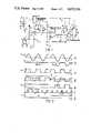
- FIG. 2shows an associated waveform diagram
- FIG. 3shows a second embodiment
- FIG. 4shows an associated waveform diagram
- a first input terminal 1is connected to a flame probe 2 and a second input terminal 3 is connected to a burner bed 4, which is nearly always connected to ground 5.
- This burner bed 4may be an outlet opening for the ignition flame 6, which when alight surrounds the probe 2, or may be the main flame grating, such as used in heating boilers and in large industrial burners.
- An alternating voltage source 7is provided in the form of a secondary of a transformer 8, the primary 9 of which is connected via terminals 10 and 11 to AC supply mains of 50 or 60 Hz, although other sources, for example of 400 Hz, are, of course, also possible.
- Source 7is connected on one end 12 to the common line 13 of the circuit and on the other end 14 to a capacitor 15 and a reference source 16.
- the capacitor 15is connected to the junction 17 of two resistors 18 and 19, one of which (18) is connected to the first input terminal 1, while the other (19) is connected to a parallel-combination of a capacitor 20 and a resistor 21 comprising a resistor 22 of a normal linear character and a voltage-dependent resistor 23 comprising two series-connected diodes a and b.
- the other side 24 of the parallel-combinationis connected to a positive voltage source 25.
- a comparison circuit 26comprises a first input 27 connected to the parallel-combination 20 and 21 and to the non-inverting input of a comparator 28 and a second input 29 connected to the inverting input and to the junction of a voltage divider comprising two resistors 30 and 31 that are connected to the reference source.
- the reference sourceproduces a rectangular waveform signal derived from the alternating voltage on the side 14 of source 7 and having the same frequency and the same phase.
- the source 16may be an amplifier which is overdriven by the input signal.
- the comparison circuithas an output 32 for the final output signal which has the first value in the absence of the flame and has the second value in the presence of the flame.
- the output 33 of the comparator 28is connected to the input 34 of a synchronous detector 35 having an output 36 connected to the final output 32 and an input 37 connected to the reference source 16 for receiving the synchronization signal.
- the synchronous detectorcan be included in a microprocessor system because of its digital decision character. However, in FIG. 1, the detector 35 is represented by a few functional blocks in order to illustrate the operation.
- a first sample and hold circuit 38receives the signal from the input 34 and from the input 37 at its inputs 39 and 40, respectively, and derives therefrom the signal value of the output signal of the comparator 28 approximately halfway through each first half cycle. This signal value is preserved for substantially one cycle and is supplied to a first input 41 of a synchronously controlled comparator 42.
- a second sample and hold circuit 43receives the said signal value from the input 34 at its input 44 and the synchronization signal at its input 45 in order to supply to the second input 46 of the comparator 42 the signal value for substantially one period shifted by a half cycle with respect to the half cycle just mentioned.
- the comparator 42decides in the time elapsing between the end of the sampling signal of the second half cycle and the subsequent sampling signal of a first half cycle, and determined by the synchronization signal at the input 47, which output signal has to be supplied via the output 36 to the final output 32, i.e. a first value for the absence of a flame or a second value for the presence of a flame.
- FIG. 2the diagrams (a) to (g) illustrate the operation of the circuit shown in FIG. 1, in which the various quantities are plotted against the time t.
- the diagram (a)shows the alternating voltage supplied by the transformer winding 7.
- Diagram (b)shows the current I flowing through the resistor 19 in the indicated direction.
- a very small alternating currentflows, which substantially does not produce any alternating voltage across the capacitor 20.
- current Iis very small in the positive part of the alternating voltage cycle, while the capacitor 15 is charged due to the rectifying effect of the flame, as indicated in dotted outline in the flame 6.
- the capacitor voltage across the capacitor 15 and the source 7 voltage between the sides 14 and 12are polarized in the same sense and give rise to a large negative current I, which charges the capacitor 20 with the indicated polarity.
- Diagram (c)shows the reference voltage, as produced by the reference source 16.
- Diagram (d)represents the input voltages at the inputs 27 and 29 of the comparison circuit 26.
- V27is the measuring direct voltage which has a first value in the absence of the flame. This first value exceeds the value of the reference voltage at the input 29 and is determined by the voltage of the source 25.
- the capacitor 20is charged and the measuring direct voltage V27 is polarized in the negative sense, as indicated by an arrow 50.
- the voltage V27is then lower than the first reference value 51 and is periodically exceeded at the frequency and phase of the alternating voltage source 7, via the reference source 16, by the reference voltage, which then assumes the value 52 (equal to zero). Since the first input 27 with receiver the voltage V27 and is connected to the non-inverting input "+" of the comparator 28, there is produced at its output 33 a rectangular signal which is in phase opposition to the reference value signal.
- Diagram (e)illustrates this output signal V33 which is a continuous positive voltage in the absence of the flame and a rectangular signal 53 in the presence of the flame.
- Diagram (f)shows sampling pulses V38-40 and V43-45.
- the result of the sampling of the signal V33is indicated by “0” and “1” within the pulses.
- the synchronously controlled comparator 42compares the signals at the inputs 41 and 46 and the output 36 supplies the second value only if V41 originating from the hold circuit 38 is a "0” and V46 originating from the hold circuit 43 is a "1", while it supplies the first value with any other combination.
- Diagram (g)represents these values. In the absence of the flame, the first value 54 is equal to zero, while in the presence of the flame the second value 55 is positive.
- FIG. 3the parts corresponding to those in FIG. 1 are designated by the same reference numerals.
- the common line or ground of the circuitis connected to the burner bed, which is grounded. However, a blocking capacitor 15 is then required.
- the circuitcan be simplified, but it then floats with respect to ground.
- FIG. 3this version is shown.
- the side 14 of the winding 7is connected through a limiting resistor 56 to the input terminal 1, while the input terminal 3 is now connected to the resistor 19.
- the parallel-combination 21is connected at side 24 to the common line 13.
- the first input 27is connected to the non-inverting input of the comparator 28 and the resistor 30 is connected to a positive voltage at the point 57.
- the circuit in which the ionization current flowsconsists of the following points and components: 13-12-7-14-56-1-2-6-4-3-19-21-24-13.
- Diagram (a)shows the alternating voltage between the points 14 and 12.
- Diagram (b)shows the current I in the absence and in the presence of the flame. Because of the direction of the current, the capacitor 20 is charged positively.
- Diagram (c)shows the reference voltage of the source 16.
- Diagram (d)shows that the first measuring direct voltage V27 is zero in the absence of the flame, that at the transition between absence of a flame and presence of a flame the measuring direct voltage is polarized in the positive sense according to the arrow 50 and that the first reference value 51 is exceeded when the second measuring direct voltage is reached.
- This first reference valueis equal to the voltage at the point 57.
- the second reference value 52is again larger than the second measuring direct voltage.
- the output 33supplies a rectangular signal which is in phase opposition to the reference signal Vref.
- Diagram (e)shows this rectangular signal 53.
- Diagram (f)illustrates the sampling pulses with the result at the hold circuit expressed in "0" and "1".
- Diagram (g)shows the final output signal 54, which is zero in the absence of the flame and has the second value 55 in the presence of the flame because the unit 42 ascertained during the period A that the signal at the input 41 was "0" and the signal at the input 46 had the value "1".
- the various supply voltagescan be controlled as to shortcircuit and interruption or against too high or too low a voltage and that for the resistors in the circuit generally, so-called film resistors (spirallized) are specified, for which open circuit is the only likely fault to occur.
Landscapes
- Engineering & Computer Science (AREA)
- Chemical & Material Sciences (AREA)
- Combustion & Propulsion (AREA)
- Mechanical Engineering (AREA)
- General Engineering & Computer Science (AREA)
- Control Of Combustion (AREA)
Abstract
Description
Claims (16)
Applications Claiming Priority (2)
| Application Number | Priority Date | Filing Date | Title |
|---|---|---|---|
| NL8401173 | 1984-04-12 | ||
| NL8401173ANL8401173A (en) | 1984-04-12 | 1984-04-12 | FLAME PROTECTION CIRCUIT. |
Publications (1)
| Publication Number | Publication Date |
|---|---|
| US4672324Atrue US4672324A (en) | 1987-06-09 |
Family
ID=19843796
Family Applications (1)
| Application Number | Title | Priority Date | Filing Date |
|---|---|---|---|
| US06/718,053Expired - LifetimeUS4672324A (en) | 1984-04-12 | 1985-03-29 | Flame protection circuit |
Country Status (6)
| Country | Link |
|---|---|
| US (1) | US4672324A (en) |
| EP (1) | EP0159748B1 (en) |
| JP (1) | JPH0721331B2 (en) |
| DE (1) | DE3567957D1 (en) |
| DK (1) | DK159485A (en) |
| NL (1) | NL8401173A (en) |
Cited By (46)
| Publication number | Priority date | Publication date | Assignee | Title |
|---|---|---|---|---|
| US4871307A (en)* | 1988-11-02 | 1989-10-03 | Harris George W | Flame ignition and monitoring system and method |
| US4955806A (en)* | 1987-09-10 | 1990-09-11 | Hamilton Standard Controls, Inc. | Integrated furnace control having ignition switch diagnostics |
| US5073104A (en)* | 1985-09-02 | 1991-12-17 | The Broken Hill Proprietary Company Limited | Flame detection |
| US5244379A (en)* | 1991-01-22 | 1993-09-14 | Henny Penny Corporation | Control system for a gas cooking device |
| US5439374A (en)* | 1993-07-16 | 1995-08-08 | Johnson Service Company | Multi-level flame curent sensing circuit |
| US5472337A (en)* | 1994-09-12 | 1995-12-05 | Guerra; Romeo E. | Method and apparatus to detect a flame |
| US5472336A (en)* | 1993-05-28 | 1995-12-05 | Honeywell Inc. | Flame rectification sensor employing pulsed excitation |
| US5578828A (en)* | 1994-11-15 | 1996-11-26 | General Electric Company | Flame sensor window coating compensation |
| US5925819A (en)* | 1995-05-10 | 1999-07-20 | Nippon Soken, Inc. | Combustion monitoring apparatus for internal combustion engine |
| US6020742A (en)* | 1996-02-09 | 2000-02-01 | Nippon Soken Inc | Combustion monitoring apparatus for internal combustion engine |
| US6104195A (en)* | 1995-05-10 | 2000-08-15 | Denso Corporation | Apparatus for detecting a condition of burning in an internal combustion engine |
| AU742228B2 (en)* | 1997-10-10 | 2001-12-20 | Siemens Schweiz Ag | Method and device for monitoring a flame |
| US6676404B2 (en)* | 2000-05-12 | 2004-01-13 | Siemens Building Technologies Ag | Measuring device for a flame |
| EP1211460A3 (en)* | 2000-12-01 | 2004-04-14 | Vaillant GmbH | Flame monitoring circuit |
| EP1460338A1 (en)* | 2003-03-21 | 2004-09-22 | Honeywell B.V. | Circuit arrangement for determining the flame current of a burner |
| US20060199122A1 (en)* | 2005-02-24 | 2006-09-07 | Alstom Technology Ltd | Self diagonostic flame ignitor |
| US20060257802A1 (en)* | 2005-05-12 | 2006-11-16 | Honeywell International Inc. | Flame sensing system |
| US20070019361A1 (en)* | 2005-05-06 | 2007-01-25 | Siemens Aktiengesellschaft | Method and device for flame monitoring |
| US20070188971A1 (en)* | 2006-02-15 | 2007-08-16 | Honeywell International Inc. | Circuit diagnostics from flame sensing ac component |
| US20090009344A1 (en)* | 2007-07-03 | 2009-01-08 | Honeywell International Inc. | Flame rod drive signal generator and system |
| US20090136883A1 (en)* | 2007-07-03 | 2009-05-28 | Honeywell International Inc. | Low cost high speed spark voltage and flame drive signal generator |
| US20100013644A1 (en)* | 2005-05-12 | 2010-01-21 | Honeywell International Inc. | Flame sensing voltage dependent on application |
| US20100265075A1 (en)* | 2005-05-12 | 2010-10-21 | Honeywell International Inc. | Leakage detection and compensation system |
| US20100291494A1 (en)* | 2009-05-15 | 2010-11-18 | Branecky Brian T | Flame rod analysis system |
| US8066508B2 (en) | 2005-05-12 | 2011-11-29 | Honeywell International Inc. | Adaptive spark ignition and flame sensing signal generation system |
| US20120268100A1 (en)* | 2011-04-21 | 2012-10-25 | Langer George O | Error compensation for current transformer sensors |
| US20130162269A1 (en)* | 2011-12-21 | 2013-06-27 | Microchip Technology Incorporated | Current Sensing with Internal ADC Capacitor |
| US8601861B1 (en)* | 2012-08-10 | 2013-12-10 | General Electric Company | Systems and methods for detecting the flame state of a combustor of a turbine engine |
| US9252769B2 (en) | 2011-10-07 | 2016-02-02 | Microchip Technology Incorporated | Microcontroller with optimized ADC controller |
| US9257980B2 (en) | 2011-10-06 | 2016-02-09 | Microchip Technology Incorporated | Measuring capacitance of a capacitive sensor with a microcontroller having digital outputs for driving a guard ring |
| US9467141B2 (en) | 2011-10-07 | 2016-10-11 | Microchip Technology Incorporated | Measuring capacitance of a capacitive sensor with a microcontroller having an analog output for driving a guard ring |
| US9494320B2 (en) | 2013-01-11 | 2016-11-15 | Honeywell International Inc. | Method and system for starting an intermittent flame-powered pilot combustion system |
| US9805572B2 (en) | 2011-10-06 | 2017-10-31 | Microchip Technology Incorporated | Differential current measurements to determine ion current in the presence of leakage current |
| US20180119955A1 (en)* | 2016-10-31 | 2018-05-03 | Robertshaw Controls Company | Flame rectification circuit using operational amplifier |
| US10042375B2 (en) | 2014-09-30 | 2018-08-07 | Honeywell International Inc. | Universal opto-coupled voltage system |
| US10208954B2 (en) | 2013-01-11 | 2019-02-19 | Ademco Inc. | Method and system for controlling an ignition sequence for an intermittent flame-powered pilot combustion system |
| US10288286B2 (en) | 2014-09-30 | 2019-05-14 | Honeywell International Inc. | Modular flame amplifier system with remote sensing |
| US10402358B2 (en) | 2014-09-30 | 2019-09-03 | Honeywell International Inc. | Module auto addressing in platform bus |
| US10473329B2 (en) | 2017-12-22 | 2019-11-12 | Honeywell International Inc. | Flame sense circuit with variable bias |
| US10678204B2 (en) | 2014-09-30 | 2020-06-09 | Honeywell International Inc. | Universal analog cell for connecting the inputs and outputs of devices |
| US10935237B2 (en) | 2018-12-28 | 2021-03-02 | Honeywell International Inc. | Leakage detection in a flame sense circuit |
| CN113446623A (en)* | 2021-06-15 | 2021-09-28 | 深圳市合信达控制系统有限公司 | Combustion state detection method and device, gas device and storage medium |
| US11236930B2 (en) | 2018-05-01 | 2022-02-01 | Ademco Inc. | Method and system for controlling an intermittent pilot water heater system |
| CN116068257A (en)* | 2023-04-06 | 2023-05-05 | 广东美智智能科技有限公司 | Flame ion current detection circuit and gas appliance |
| US11656000B2 (en) | 2019-08-14 | 2023-05-23 | Ademco Inc. | Burner control system |
| US11739982B2 (en) | 2019-08-14 | 2023-08-29 | Ademco Inc. | Control system for an intermittent pilot water heater |
Families Citing this family (10)
| Publication number | Priority date | Publication date | Assignee | Title |
|---|---|---|---|---|
| JPS60232422A (en)* | 1984-05-02 | 1985-11-19 | Matsushita Electric Ind Co Ltd | Flame current detection device |
| JPS6336838U (en)* | 1986-08-28 | 1988-03-09 | ||
| GB2252436A (en)* | 1991-02-04 | 1992-08-05 | Black Automatic Controls Limit | Flame detection circuit and method |
| KR950005093B1 (en)* | 1991-06-28 | 1995-05-18 | 삼성전자주식회사 | Flame load |
| DE4122636C2 (en)* | 1991-07-09 | 1999-08-12 | Bosch Gmbh Robert | Device and method for monitoring a flame |
| GB2286888A (en)* | 1994-02-23 | 1995-08-30 | Cambridge Consultants | Capacitive combustion sensor |
| AT410172B (en) | 2000-03-21 | 2003-02-25 | Igeneon Gmbh | METHOD FOR PRODUCING VACCINE FORMULATION |
| GB2367172B (en)* | 2000-04-26 | 2004-02-18 | Pektron Group Ltd | Detection apparatus and a method of detection |
| DE102007018122B4 (en)* | 2007-04-16 | 2013-10-17 | Viessmann Werke Gmbh & Co Kg | Flame monitoring device with a voltage generating and measuring arrangement and method for monitoring a burner by means of the flame monitoring device |
| DE102020108006A1 (en) | 2020-03-24 | 2021-09-30 | Ebm-Papst Landshut Gmbh | Circuit device and method for monitoring a burner flame |
Citations (2)
| Publication number | Priority date | Publication date | Assignee | Title |
|---|---|---|---|---|
| US4300099A (en)* | 1978-06-07 | 1981-11-10 | Hochiki Corporation | Fire detecting system |
| US4527125A (en)* | 1981-11-13 | 1985-07-02 | Hitachi, Ltd. | Flame detecting apparatus |
Family Cites Families (6)
| Publication number | Priority date | Publication date | Assignee | Title |
|---|---|---|---|---|
| GB730619A (en)* | 1953-04-13 | 1955-05-25 | Rheostatic Co Ltd | Improvements in devices for protecting furnaces at times of flame failure |
| US4000961A (en)* | 1975-08-26 | 1977-01-04 | Eclipse, Inc. | Primary flame safeguard system |
| JPS54125537A (en)* | 1978-03-24 | 1979-09-29 | Hitachi Ltd | Lighting-fire detection device |
| US4188181A (en)* | 1978-04-24 | 1980-02-12 | Emerson Electric Co. | Gas burner control system |
| JPS5714122A (en)* | 1980-07-01 | 1982-01-25 | Mitsubishi Electric Corp | Oxygen density detecting apparatus for burner |
| JPS60232422A (en)* | 1984-05-02 | 1985-11-19 | Matsushita Electric Ind Co Ltd | Flame current detection device |
- 1984
- 1984-04-12NLNL8401173Apatent/NL8401173A/ennot_activeApplication Discontinuation
- 1985
- 1985-03-29USUS06/718,053patent/US4672324A/ennot_activeExpired - Lifetime
- 1985-04-01DEDE8585200509Tpatent/DE3567957D1/ennot_activeExpired
- 1985-04-01EPEP85200509Apatent/EP0159748B1/ennot_activeExpired
- 1985-04-09DKDK159485Apatent/DK159485A/ennot_activeIP Right Cessation
- 1985-04-09JPJP60073628Apatent/JPH0721331B2/ennot_activeExpired - Lifetime
Patent Citations (2)
| Publication number | Priority date | Publication date | Assignee | Title |
|---|---|---|---|---|
| US4300099A (en)* | 1978-06-07 | 1981-11-10 | Hochiki Corporation | Fire detecting system |
| US4527125A (en)* | 1981-11-13 | 1985-07-02 | Hitachi, Ltd. | Flame detecting apparatus |
Cited By (63)
| Publication number | Priority date | Publication date | Assignee | Title |
|---|---|---|---|---|
| US5073104A (en)* | 1985-09-02 | 1991-12-17 | The Broken Hill Proprietary Company Limited | Flame detection |
| US4955806A (en)* | 1987-09-10 | 1990-09-11 | Hamilton Standard Controls, Inc. | Integrated furnace control having ignition switch diagnostics |
| US4871307A (en)* | 1988-11-02 | 1989-10-03 | Harris George W | Flame ignition and monitoring system and method |
| US5244379A (en)* | 1991-01-22 | 1993-09-14 | Henny Penny Corporation | Control system for a gas cooking device |
| US5472336A (en)* | 1993-05-28 | 1995-12-05 | Honeywell Inc. | Flame rectification sensor employing pulsed excitation |
| US5439374A (en)* | 1993-07-16 | 1995-08-08 | Johnson Service Company | Multi-level flame curent sensing circuit |
| US5472337A (en)* | 1994-09-12 | 1995-12-05 | Guerra; Romeo E. | Method and apparatus to detect a flame |
| US5578828A (en)* | 1994-11-15 | 1996-11-26 | General Electric Company | Flame sensor window coating compensation |
| US5925819A (en)* | 1995-05-10 | 1999-07-20 | Nippon Soken, Inc. | Combustion monitoring apparatus for internal combustion engine |
| US6104195A (en)* | 1995-05-10 | 2000-08-15 | Denso Corporation | Apparatus for detecting a condition of burning in an internal combustion engine |
| US6020742A (en)* | 1996-02-09 | 2000-02-01 | Nippon Soken Inc | Combustion monitoring apparatus for internal combustion engine |
| AU742228B2 (en)* | 1997-10-10 | 2001-12-20 | Siemens Schweiz Ag | Method and device for monitoring a flame |
| US6676404B2 (en)* | 2000-05-12 | 2004-01-13 | Siemens Building Technologies Ag | Measuring device for a flame |
| EP1211460A3 (en)* | 2000-12-01 | 2004-04-14 | Vaillant GmbH | Flame monitoring circuit |
| EP1460338A1 (en)* | 2003-03-21 | 2004-09-22 | Honeywell B.V. | Circuit arrangement for determining the flame current of a burner |
| US20060199122A1 (en)* | 2005-02-24 | 2006-09-07 | Alstom Technology Ltd | Self diagonostic flame ignitor |
| US7492269B2 (en)* | 2005-02-24 | 2009-02-17 | Alstom Technology Ltd | Self diagonostic flame ignitor |
| US7382140B2 (en)* | 2005-05-06 | 2008-06-03 | Siemens Building Technologies Hvac Products Gmbh | Method and device for flame monitoring |
| US20070019361A1 (en)* | 2005-05-06 | 2007-01-25 | Siemens Aktiengesellschaft | Method and device for flame monitoring |
| US7764182B2 (en)* | 2005-05-12 | 2010-07-27 | Honeywell International Inc. | Flame sensing system |
| US8659437B2 (en) | 2005-05-12 | 2014-02-25 | Honeywell International Inc. | Leakage detection and compensation system |
| US20100013644A1 (en)* | 2005-05-12 | 2010-01-21 | Honeywell International Inc. | Flame sensing voltage dependent on application |
| US20060257802A1 (en)* | 2005-05-12 | 2006-11-16 | Honeywell International Inc. | Flame sensing system |
| US20100265075A1 (en)* | 2005-05-12 | 2010-10-21 | Honeywell International Inc. | Leakage detection and compensation system |
| US8310801B2 (en) | 2005-05-12 | 2012-11-13 | Honeywell International, Inc. | Flame sensing voltage dependent on application |
| US8066508B2 (en) | 2005-05-12 | 2011-11-29 | Honeywell International Inc. | Adaptive spark ignition and flame sensing signal generation system |
| US8875557B2 (en) | 2006-02-15 | 2014-11-04 | Honeywell International Inc. | Circuit diagnostics from flame sensing AC component |
| US20070188971A1 (en)* | 2006-02-15 | 2007-08-16 | Honeywell International Inc. | Circuit diagnostics from flame sensing ac component |
| US8300381B2 (en) | 2007-07-03 | 2012-10-30 | Honeywell International Inc. | Low cost high speed spark voltage and flame drive signal generator |
| US8085521B2 (en) | 2007-07-03 | 2011-12-27 | Honeywell International Inc. | Flame rod drive signal generator and system |
| US20090136883A1 (en)* | 2007-07-03 | 2009-05-28 | Honeywell International Inc. | Low cost high speed spark voltage and flame drive signal generator |
| US20090009344A1 (en)* | 2007-07-03 | 2009-01-08 | Honeywell International Inc. | Flame rod drive signal generator and system |
| US20100291494A1 (en)* | 2009-05-15 | 2010-11-18 | Branecky Brian T | Flame rod analysis system |
| US10697921B2 (en)* | 2009-05-15 | 2020-06-30 | A. O. Smith Corporation | Flame rod analysis system |
| US10132770B2 (en)* | 2009-05-15 | 2018-11-20 | A. O. Smith Corporation | Flame rod analysis system |
| US9053852B2 (en)* | 2011-04-21 | 2015-06-09 | Magnelab, Inc. | Error compensation for current transformer sensors |
| US20120268100A1 (en)* | 2011-04-21 | 2012-10-25 | Langer George O | Error compensation for current transformer sensors |
| US9805572B2 (en) | 2011-10-06 | 2017-10-31 | Microchip Technology Incorporated | Differential current measurements to determine ion current in the presence of leakage current |
| US9257980B2 (en) | 2011-10-06 | 2016-02-09 | Microchip Technology Incorporated | Measuring capacitance of a capacitive sensor with a microcontroller having digital outputs for driving a guard ring |
| US9252769B2 (en) | 2011-10-07 | 2016-02-02 | Microchip Technology Incorporated | Microcontroller with optimized ADC controller |
| US9467141B2 (en) | 2011-10-07 | 2016-10-11 | Microchip Technology Incorporated | Measuring capacitance of a capacitive sensor with a microcontroller having an analog output for driving a guard ring |
| US9823280B2 (en)* | 2011-12-21 | 2017-11-21 | Microchip Technology Incorporated | Current sensing with internal ADC capacitor |
| US20130162269A1 (en)* | 2011-12-21 | 2013-06-27 | Microchip Technology Incorporated | Current Sensing with Internal ADC Capacitor |
| US8601861B1 (en)* | 2012-08-10 | 2013-12-10 | General Electric Company | Systems and methods for detecting the flame state of a combustor of a turbine engine |
| US10429068B2 (en) | 2013-01-11 | 2019-10-01 | Ademco Inc. | Method and system for starting an intermittent flame-powered pilot combustion system |
| US10208954B2 (en) | 2013-01-11 | 2019-02-19 | Ademco Inc. | Method and system for controlling an ignition sequence for an intermittent flame-powered pilot combustion system |
| US11268695B2 (en) | 2013-01-11 | 2022-03-08 | Ademco Inc. | Method and system for starting an intermittent flame-powered pilot combustion system |
| US9494320B2 (en) | 2013-01-11 | 2016-11-15 | Honeywell International Inc. | Method and system for starting an intermittent flame-powered pilot combustion system |
| US11719436B2 (en) | 2013-01-11 | 2023-08-08 | Ademco Inc. | Method and system for controlling an ignition sequence for an intermittent flame-powered pilot combustion system |
| US10042375B2 (en) | 2014-09-30 | 2018-08-07 | Honeywell International Inc. | Universal opto-coupled voltage system |
| US10288286B2 (en) | 2014-09-30 | 2019-05-14 | Honeywell International Inc. | Modular flame amplifier system with remote sensing |
| US10402358B2 (en) | 2014-09-30 | 2019-09-03 | Honeywell International Inc. | Module auto addressing in platform bus |
| US10678204B2 (en) | 2014-09-30 | 2020-06-09 | Honeywell International Inc. | Universal analog cell for connecting the inputs and outputs of devices |
| US20180119955A1 (en)* | 2016-10-31 | 2018-05-03 | Robertshaw Controls Company | Flame rectification circuit using operational amplifier |
| US10890326B2 (en)* | 2016-10-31 | 2021-01-12 | Robertshaw Controls Company | Flame rectification circuit using operational amplifier |
| US10473329B2 (en) | 2017-12-22 | 2019-11-12 | Honeywell International Inc. | Flame sense circuit with variable bias |
| US11236930B2 (en) | 2018-05-01 | 2022-02-01 | Ademco Inc. | Method and system for controlling an intermittent pilot water heater system |
| US11719467B2 (en) | 2018-05-01 | 2023-08-08 | Ademco Inc. | Method and system for controlling an intermittent pilot water heater system |
| US10935237B2 (en) | 2018-12-28 | 2021-03-02 | Honeywell International Inc. | Leakage detection in a flame sense circuit |
| US11656000B2 (en) | 2019-08-14 | 2023-05-23 | Ademco Inc. | Burner control system |
| US11739982B2 (en) | 2019-08-14 | 2023-08-29 | Ademco Inc. | Control system for an intermittent pilot water heater |
| CN113446623A (en)* | 2021-06-15 | 2021-09-28 | 深圳市合信达控制系统有限公司 | Combustion state detection method and device, gas device and storage medium |
| CN116068257A (en)* | 2023-04-06 | 2023-05-05 | 广东美智智能科技有限公司 | Flame ion current detection circuit and gas appliance |
Also Published As
| Publication number | Publication date |
|---|---|
| DK159485D0 (en) | 1985-04-09 |
| EP0159748B1 (en) | 1989-01-25 |
| DK159485A (en) | 1985-10-13 |
| EP0159748A1 (en) | 1985-10-30 |
| JPH0721331B2 (en) | 1995-03-08 |
| JPS60233422A (en) | 1985-11-20 |
| DE3567957D1 (en) | 1989-03-02 |
| NL8401173A (en) | 1985-11-01 |
Similar Documents
| Publication | Publication Date | Title |
|---|---|---|
| US4672324A (en) | Flame protection circuit | |
| US6676404B2 (en) | Measuring device for a flame | |
| US3995200A (en) | Ground monitor and circuit breaker actuating device | |
| US6501383B1 (en) | Method and device for monitoring a flame | |
| EP0241903A2 (en) | Ground fault detector for high-voltage DC power supplies | |
| EP0071067A1 (en) | Combustion control device | |
| GB2051446A (en) | Detecting broken filaments in lamps | |
| US2748846A (en) | Combustion safeguard apparatus | |
| US4527125A (en) | Flame detecting apparatus | |
| US2556961A (en) | Flame detection apparatus | |
| CN108006694B (en) | Flame rectification circuit using operational amplifier | |
| US2528589A (en) | Control apparatus | |
| US5194728A (en) | Circuit for detecting firing of an ultraviolet radiation detector tube | |
| GB2153126A (en) | Self-monitoring flame monitor | |
| US4024438A (en) | Delta phase loss detector | |
| US2632102A (en) | Flame detection apparatus | |
| JPS61260598A (en) | Gas discharge lamp lighting circuit array | |
| US3060351A (en) | Voltage responsive control circuit | |
| CA2231893C (en) | Inspecting system for welding apparatus | |
| US3534349A (en) | Data transmission systems | |
| EP0573223A1 (en) | Heating appliances | |
| RU2440536C2 (en) | Device to measure intensive flame | |
| KR0146927B1 (en) | Electric Rice Cooker | |
| KR930005833Y1 (en) | Beam current automatic control circuit | |
| AU654900B2 (en) | Infrared-based sensing circuit providing an output simulating the output of a flame rod sensor |
Legal Events
| Date | Code | Title | Description |
|---|---|---|---|
| AS | Assignment | Owner name:U.S. PHILIPS CORPORATON, 100 EAST 42ND STREET, NEW Free format text:ASSIGNMENT OF ASSIGNORS INTEREST.;ASSIGNOR:VAN KAMPEN, JAN;REEL/FRAME:004415/0850 Effective date:19850528 | |
| STCF | Information on status: patent grant | Free format text:PATENTED CASE | |
| FEPP | Fee payment procedure | Free format text:PAYOR NUMBER ASSIGNED (ORIGINAL EVENT CODE: ASPN); ENTITY STATUS OF PATENT OWNER: LARGE ENTITY | |
| FPAY | Fee payment | Year of fee payment:4 | |
| FEPP | Fee payment procedure | Free format text:PAYER NUMBER DE-ASSIGNED (ORIGINAL EVENT CODE: RMPN); ENTITY STATUS OF PATENT OWNER: LARGE ENTITY | |
| AS | Assignment | Owner name:GASMODUL B.V, NETHERLANDS Free format text:ASSIGNMENT OF ASSIGNORS INTEREST;ASSIGNOR:U.S. PHILIPS CORPORATION;REEL/FRAME:006773/0743 Effective date:19931102 | |
| FPAY | Fee payment | Year of fee payment:8 | |
| FEPP | Fee payment procedure | Free format text:PAYOR NUMBER ASSIGNED (ORIGINAL EVENT CODE: ASPN); ENTITY STATUS OF PATENT OWNER: LARGE ENTITY | |
| FEPP | Fee payment procedure | Free format text:PAT HOLDER CLAIMS SMALL ENTITY STATUS - SMALL BUSINESS (ORIGINAL EVENT CODE: SM02); ENTITY STATUS OF PATENT OWNER: LARGE ENTITY | |
| AS | Assignment | Owner name:GASMODUL, B.V., NETHERLANDS Free format text:CHANGE OF ADDRESS OF ASSIGNEE;ASSIGNOR:GASMODUL, B.V.;REEL/FRAME:008423/0594 Effective date:19961023 | |
| FEPP | Fee payment procedure | Free format text:PAT HLDR NO LONGER CLAIMS SMALL ENT STAT AS SMALL BUSINESS (ORIGINAL EVENT CODE: LSM2); ENTITY STATUS OF PATENT OWNER: LARGE ENTITY | |
| FPAY | Fee payment | Year of fee payment:12 |