US4671276A - Apparatus for corneal curvature adjustment - Google Patents
Apparatus for corneal curvature adjustmentDownload PDFInfo
- Publication number
- US4671276A US4671276AUS06/579,480US57948084AUS4671276AUS 4671276 AUS4671276 AUS 4671276AUS 57948084 AUS57948084 AUS 57948084AUS 4671276 AUS4671276 AUS 4671276A
- Authority
- US
- United States
- Prior art keywords
- ring
- cornea
- cutting member
- dissecting
- adjusting
- Prior art date
- Legal status (The legal status is an assumption and is not a legal conclusion. Google has not performed a legal analysis and makes no representation as to the accuracy of the status listed.)
- Expired - Lifetime
Links
- 210000004087corneaAnatomy0.000claimsabstractdescription93
- 238000003780insertionMethods0.000claimsabstractdescription15
- 230000037431insertionEffects0.000claimsabstractdescription15
- 229920003023plasticPolymers0.000abstractdescription5
- 230000000007visual effectEffects0.000abstractdescription5
- 239000002184metalSubstances0.000abstractdescription4
- 238000012876topographyMethods0.000abstractdescription3
- 230000008859changeEffects0.000abstractdescription2
- 238000000034methodMethods0.000description26
- 210000001525retinaAnatomy0.000description24
- 210000001519tissueAnatomy0.000description10
- 230000003287optical effectEffects0.000description7
- 241000446313LamellaSpecies0.000description6
- 230000000694effectsEffects0.000description6
- 239000012530fluidSubstances0.000description5
- 239000010410layerSubstances0.000description5
- 239000000463materialSubstances0.000description5
- 208000014733refractive errorDiseases0.000description5
- 238000012937correctionMethods0.000description4
- 230000006870functionEffects0.000description4
- 230000000860keratorefractive effectEffects0.000description4
- 230000004379myopiaEffects0.000description4
- 208000001491myopiaDiseases0.000description4
- 206010020675HypermetropiaDiseases0.000description3
- 210000004556brainAnatomy0.000description3
- 230000001886ciliary effectEffects0.000description3
- 210000003683corneal stromaAnatomy0.000description3
- 230000004305hyperopiaEffects0.000description3
- 201000006318hyperopiaDiseases0.000description3
- 210000005036nerveAnatomy0.000description3
- 210000001328optic nerveAnatomy0.000description3
- CURLTUGMZLYLDI-UHFFFAOYSA-NCarbon dioxideChemical compoundO=C=OCURLTUGMZLYLDI-UHFFFAOYSA-N0.000description2
- 230000004430ametropiaEffects0.000description2
- 210000002159anterior chamberAnatomy0.000description2
- 201000009310astigmatismDiseases0.000description2
- 210000004045bowman membraneAnatomy0.000description2
- 210000004027cellAnatomy0.000description2
- 210000003161choroidAnatomy0.000description2
- 210000004240ciliary bodyAnatomy0.000description2
- 230000007423decreaseEffects0.000description2
- 210000002919epithelial cellAnatomy0.000description2
- 238000002513implantationMethods0.000description2
- 208000014674injuryDiseases0.000description2
- 238000012986modificationMethods0.000description2
- 230000004048modificationEffects0.000description2
- 210000003205muscleAnatomy0.000description2
- 230000008569processEffects0.000description2
- 210000004129prosencephalonAnatomy0.000description2
- 210000001747pupilAnatomy0.000description2
- 210000003786scleraAnatomy0.000description2
- 238000001356surgical procedureMethods0.000description2
- 238000012546transferMethods0.000description2
- 230000008733traumaEffects0.000description2
- 102000004190EnzymesHuman genes0.000description1
- 108090000790EnzymesProteins0.000description1
- 229920002527GlycogenPolymers0.000description1
- VVQNEPGJFQJSBK-UHFFFAOYSA-NMethyl methacrylateChemical compoundCOC(=O)C(C)=CVVQNEPGJFQJSBK-UHFFFAOYSA-N0.000description1
- 208000037273Pathologic ProcessesDiseases0.000description1
- 229920005372Plexiglas®Polymers0.000description1
- 208000029091Refraction diseaseDiseases0.000description1
- 229910000831SteelInorganic materials0.000description1
- 206010044625TrichorrhexisDiseases0.000description1
- 206010047513Vision blurredDiseases0.000description1
- OIPILFWXSMYKGL-UHFFFAOYSA-NacetylcholineChemical compoundCC(=O)OCC[N+](C)(C)COIPILFWXSMYKGL-UHFFFAOYSA-N0.000description1
- 229960004373acetylcholineDrugs0.000description1
- 238000004026adhesive bondingMethods0.000description1
- 230000004075alterationEffects0.000description1
- 229910002092carbon dioxideInorganic materials0.000description1
- 239000001569carbon dioxideSubstances0.000description1
- 239000011248coating agentSubstances0.000description1
- 238000000576coating methodMethods0.000description1
- 210000000795conjunctivaAnatomy0.000description1
- 210000002555descemet membraneAnatomy0.000description1
- 238000011161developmentMethods0.000description1
- 238000010586diagramMethods0.000description1
- 238000009792diffusion processMethods0.000description1
- 230000003467diminishing effectEffects0.000description1
- 229940088598enzymeDrugs0.000description1
- 210000000981epitheliumAnatomy0.000description1
- 230000004438eyesightEffects0.000description1
- 239000000835fiberSubstances0.000description1
- 239000011521glassSubstances0.000description1
- 229940096919glycogenDrugs0.000description1
- 239000007943implantSubstances0.000description1
- 239000000696magnetic materialSubstances0.000description1
- 238000005259measurementMethods0.000description1
- 210000004379membraneAnatomy0.000description1
- 239000012528membraneSubstances0.000description1
- 230000005499meniscusEffects0.000description1
- 239000007769metal materialSubstances0.000description1
- 210000004126nerve fiberAnatomy0.000description1
- 230000000050nutritive effectEffects0.000description1
- 230000009054pathological processEffects0.000description1
- 108091008695photoreceptorsProteins0.000description1
- 230000001681protective effectEffects0.000description1
- 238000011160researchMethods0.000description1
- 230000002207retinal effectEffects0.000description1
- 231100000241scarToxicity0.000description1
- 230000037390scarringEffects0.000description1
- 230000035807sensationEffects0.000description1
- 238000004904shorteningMethods0.000description1
- 239000002356single layerSubstances0.000description1
- 239000007787solidSubstances0.000description1
- 229910001220stainless steelInorganic materials0.000description1
- 239000010935stainless steelSubstances0.000description1
- 239000010959steelSubstances0.000description1
- 230000007704transitionEffects0.000description1
- 230000002792vascularEffects0.000description1
- XLYOFNOQVPJJNP-UHFFFAOYSA-NwaterSubstancesOXLYOFNOQVPJJNP-UHFFFAOYSA-N0.000description1
Images


Classifications
- A—HUMAN NECESSITIES
- A61—MEDICAL OR VETERINARY SCIENCE; HYGIENE
- A61F—FILTERS IMPLANTABLE INTO BLOOD VESSELS; PROSTHESES; DEVICES PROVIDING PATENCY TO, OR PREVENTING COLLAPSING OF, TUBULAR STRUCTURES OF THE BODY, e.g. STENTS; ORTHOPAEDIC, NURSING OR CONTRACEPTIVE DEVICES; FOMENTATION; TREATMENT OR PROTECTION OF EYES OR EARS; BANDAGES, DRESSINGS OR ABSORBENT PADS; FIRST-AID KITS
- A61F2/00—Filters implantable into blood vessels; Prostheses, i.e. artificial substitutes or replacements for parts of the body; Appliances for connecting them with the body; Devices providing patency to, or preventing collapsing of, tubular structures of the body, e.g. stents
- A61F2/02—Prostheses implantable into the body
- A61F2/14—Eye parts, e.g. lenses or corneal implants; Artificial eyes
- A61F2/147—Implants to be inserted in the stroma for refractive correction, e.g. ring-like implants
- A—HUMAN NECESSITIES
- A61—MEDICAL OR VETERINARY SCIENCE; HYGIENE
- A61F—FILTERS IMPLANTABLE INTO BLOOD VESSELS; PROSTHESES; DEVICES PROVIDING PATENCY TO, OR PREVENTING COLLAPSING OF, TUBULAR STRUCTURES OF THE BODY, e.g. STENTS; ORTHOPAEDIC, NURSING OR CONTRACEPTIVE DEVICES; FOMENTATION; TREATMENT OR PROTECTION OF EYES OR EARS; BANDAGES, DRESSINGS OR ABSORBENT PADS; FIRST-AID KITS
- A61F9/00—Methods or devices for treatment of the eyes; Devices for putting in contact-lenses; Devices to correct squinting; Apparatus to guide the blind; Protective devices for the eyes, carried on the body or in the hand
- A61F9/007—Methods or devices for eye surgery
- A61F9/013—Instruments for compensation of ocular refraction ; Instruments for use in cornea removal, for reshaping or performing incisions in the cornea
- B—PERFORMING OPERATIONS; TRANSPORTING
- B21—MECHANICAL METAL-WORKING WITHOUT ESSENTIALLY REMOVING MATERIAL; PUNCHING METAL
- B21F—WORKING OR PROCESSING OF METAL WIRE
- B21F45/00—Wire-working in the manufacture of other particular articles
- B21F45/008—Wire-working in the manufacture of other particular articles of medical instruments, e.g. stents, corneal rings
Definitions
- This inventionrelates to a method and apparatus for adjusting the shape of components of the eye and more particularly to making fixed changes in the corneal curvature.
- Deviations form the normal shape of the corneal surfaceproduce errors of refraction in the visual process.
- the eye in a state of rest, without accomodationfocuses the image of distant objects exactly on the retina. Such an eye enjoys distinct vision for distant objects without effort.
- Any variation from this standardconstitutes ametropia, a condition in which the eye at rest is unable to focus the image of a distant object on the retina.
- Hyperopiais an error of refraction in which, with the eye at rest, parallel rays from distant objects are brought to focus behind the retina. Divergent rays from near objects are focused still further back.
- the corneal surfaceis flattened which decreases the angle of refraction of rays as they pass through the refractive surfaces of the cornea, causing a convergence or focus of the rays at a point behind the retina.
- the retinais comprised partially of nerve fibers which are an expansion of the optic nerve. Waves of light falling on the retina are converted into nerve impulses and carried by the optic nerve to the brain to produce the sensation of light.
- the hyperopic eyemust either accomodate, i.e., increase the convexity of its lens, or a convex lens of sufficient strength to focus rays on the retina must be placed before the eye.
- Myopiais that refractive condition in which, with accomodation completely relaxed, parallel rays are brought to focus in front of the retina.
- One condition which commonly causes myopiais when the corneal curvature is steepened, thus the refraction of rays is greater as they pass through the refractive surfaces of the cornea, and the over refracted rays converge or focus in front of the retina in the vitreous of the eye.
- the raysreach the retina they become divergent, forming a circle of diffusion and consequently a blurred image.
- a concave lensis used to correct the focus of the eye for myopia.
- KeratophakiaThe normal treatment of these classic forms of refractive error of the eye is with the use of eyeglasses or contact lenses, both of which have well-known disadvantages to the user.
- Recent researchhas been directed to operative techniques to change the refractive condition of the eye. Such techniques are generally referred to "keratorefractive techniques". Two such techniques are more particularly called keratophakia and keratomileusis. Keralomileusis involves the regrinding of a corneal lamella into a meniscus or hyperopic lens to correct myopia or hyperopia.
- a corneal optical lathehas been especially developed for this procedure and is also used in the keratophakia procedure, when a homograft ground into a convex lens is placed interlamellarly to correct aphakic hypermetropia.
- the homograft tissue(corneal lamella) is frozen with carbon dioxide.
- the homograftis cut as a contact lens would be, i.e., to the optical power required to effect the desired optical correction of the cornea.
- the anterior corneal lamellais shaped by the lathe and in keratophobia, it is the corneal stroma of a donor eye that is shaped by the lathe.
- the effect of a peripherical distoring forcemay be easily visualized by imagining an inflated balloon with a spherical surface being compressed between the palms of the hands. Because the volume of air in the balloon is constant, the surface area remains constant. The previously spherical anterior surface is distorted meridianally as a result of compressing the diameter between the hands so that the curvature changes without changing the circumference of the surface. The meridian passing over the balloon between the extended fingers steepens, while the uncompressed meridian at right angles thereto flattens as its diameter lengthens in proportion to the shortening of the compressed diameter.
- Another aspect of the inventioninvolves an ovaloid cross sectional shape of the adjusting ring which when inserted in the cornea is arranged to have its major cross sectional axis aligned with a corneal arc extending through the anterior pole of the cornea.
- An additional aspect of the inventioninvolves a dissecting ring which has split end portions, with one end being inserted into the cornea prior to insertion of the adjusting ring. Such one end is then moved in a circular path about the interior of the cornea until it reaches the insertion point, whereupon the one end of the adjusting ring is releasably attached to the one end of the dissecting ring and the dissecting ring is then moved in a reversed circular path, pulling the now attached adjusting ring behind it until the one end of the dissecting ring has returned to the insertion point.
- the one end of the adjusting ringhas also circularly moved about the interior of the cornea until its one leading end has reached the insertion point to implant the adjusting ring in the cornea and withdraw the dissecting ring.
- the corneal curvature adjusting procedure and ring end fixing procedureare then performed.
- Still another aspect of the inventionis the shape of the one leading end of the respective dissecting ring and adjusting ring which is asymmetrically rounded into a sled shape to maintain a transverse bias on the one ends as they are moved within the corneal tissue.
- Yet another aspect of the inventionpertains to a connecting system for releasably attaching the leading ends of the respective dissecting and adjusting rings, including holes near the tip ends of the one end of the rings with longitudinal grooves extending from the holes to the tip ends, and an inverted "U-shaped" clip which is inserted in the holes of both rings to hold the ring ends together while they are being moved about the interior of the cornea.
- a ring holder and moving devicewhich is comprised of an elongated cylindrical member having a concave surface formed concentrically within its lower end and sized to fit over the curvature of the cornea, with a circular groove in the face of the concave surface, which groove is sized to hold the dissecting ring in its circular configuration, and a means for exerting a magnetic force on the dissecting ring to cause the ring to follow the rotational path of the holder when it is rotated over the eye after the one end of the dissecting ring is inserted into the corneal tissue.
- This magnetic forcealso pulls the dissecting ring toward the anterior of the corneal stroma into which it is being inserted.
- a pinextends outwardly from the groove and serves to engage a blunt trailing end of the dissecting ring as it is being inserted to further facilitate its movement in and about the cornea as the holder is rotated.
- a cylindrical sleevemay be fitted over a portion of the elongated cylindrical member to facilitate holding the holding device steady as the cylindrical member is rotated in the adjusting ring insertion procedure.
- Yet still another aspect of the inventionresides in providing visual indication of the present shape of the cornea together with an indication of a desired shape and comparing the indications while the adjusting ring ends are being adjusted to aid in fixing the ends of the adjusting ring at a place to provide the desired corneal topography.
- FIG. 1is a schematic illustration of a horizontal section of the eye
- FIG. 2is a schematic illustration of an eye system showing adjustment of the cornea to steepen the corneal slope
- FIG. 3is a schematic illustration of an eye system showing adjustment of the cornea to flatten the corneal slope
- FIG. 4is a more detailed schematic illustration of a horizontal section of the frontal portion of the eye showing an adjusting ring positioned in the stroma of the cornea;
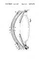
- FIG. 5is a plan view of a dissecting ring showing its end portions
- FIG. 6is a plan view of an adjustment ring showing its end portions
- FIG. 7is an elevational view showing the inserting ends of the respective dissecting ring and adjustment rings positioned for receiving a releasable connecting clip
- FIG. 8is an elevational view of the adjusting ring taken along lines 8--8 of FIG. 6;
- FIG. 9is a partial perspective view of the cornea of an eye with incisions for receiving the dissecting and adjusting rings and the rings positioned for releasable attachment to one another just prior to implanting the adjusting ring;
- FIG. 10is a side elevational cross sectional view of a dissecting ring holding and rotating tool.
- FIG. 11is a schematic representation of a cornea-scope type image superimposed with a target image for comparing the present shape of the cornea with a desired shape to permit accurate fixing of the adjustment ring to fix the shape of the cornea.
- FIG. 1 of the drawingsa horizontal section of the eye shows the globe of the eye resembling a sphere with an anterior bulged spherical portion 12 representing the cornea.
- the eyeis actually comprised of two somewhat modified spheres placed one in front of the other. The anterior of these two segments is the smaller more curved cornea.
- the globe of the eyeconsists of three concentric coverings enclosing the various transparent media through which the light must pass before reaching the sensitive retina.
- the outermost coveringis a fibrous protective portion the posterior five-sixths of which is white and opaque and called the sclera 13, and sometimes referred to as the white of the eye where visable to the front.
- the anterior one-sixth of this outer layeris the transparent cornea 12.
- a middle coveringis mainly vascular and nutritive in function and is comprised of the choroid 14, cibiary body 15 and iris 17.
- the choroidgenerally functions to maintain the retina.
- the ciliary muscleis involved in suspending the lens and accomodation of the lens.
- the irisis the most anterior portion of the middle covering of the eye and is arranged in a frontal plane. It is a thin circular disc corresponding to the diaphram of a camera, and is perforated near its center by a circular aperature called the pupil 19.
- the size of the pupilvaries to regulate the amount of light which reaches the retina. It contracts also to accomodation, which serves to sharpen the focus by diminishing spherical aberration.
- the irisdivides the space between the cornea 12 and the lens 21 into an anterior chamber 22 and posterior chamber 23.
- the innermost portion of coveringis the retina 18, consisting of nerve elements which form the true receptive portion for visual impressions.
- the retinais a part of the brain arising as an outgrowth from the fore-brain, with the optic nerve 24 serving as a fibre tract connecting the retina part of the brain with the fore-brain.
- the vitreous 26is a transparent gelatinous mass which fills the posterior four-fifths of the globe. At its sides it supports the ciliary body 16 and the retina 18. A frontal saucer-shaped depression houses the lens 21.
- the lens 21 of the eyeis a transparent bi-convex body of crystalline appearance placed between the iris 17 and vitreous 26. Its axial diameter varies markedly with accomodation.
- a ciliary zonule 27, consisting of transparent fibres passing between the ciliary body 16 and lens 21serves to hold the lens in position and enable the ciliary muscle to act on it.
- this outermost fibrous transparent coatingresembles a watch glass. Its curvature is somewhat greater than the rest of the globe and is ideally spherical in nature. However, often it is more curved in one meridian than another giving rise to astigmatism. A central third of the cornea is called the optical zone with a slight flattening taking place outwardly thereof as the cornea thickens towards its periphery. Most of the refraction of the eye takes place on the surface of the cornea.
- a more detailed drawing of the anterior portion of the globeshows the various layers of the cornea comprising an epitheluim 31.
- Epithelial cells on the surface thereoffunction to maintain transparency of the cornea. These epithelial cells are rich in glycogen, enzymes and acetylcholine and their activity regulates the corneal corpuscles and controls the transport of water and electrolyles through the lamellae of the stroma 32 of the cornea.
- An anterior limiting lamina 33is positioned between the epithelium 31 and the substantia intestinal or stroma 32 of the cornea.
- the stromais comprised of lamella having bands of fibrils parallel to each other and crossing the whole of the cornea. While most of the fibrous bands are parallel to the surface, some are oblique, especially anteriorly. The fibrous bands within alternate lamella are at a near right angle to bands in the adjacent lamella.
- a posterior limiting lamina 34is referred to as Descemet's membrane. It is a strong membrane sharply defined from the stroma and resistant to pathological processes of the cornea.
- the endotheluim 36is the most posterior layer of the cornea and consists of a single layer of cells.
- the limbus 37is the transition zone between the conjunctiva 38 and sclera 13 on the one hand and the cornea 12 on the other.
- FIG. 2 of the drawingsthe globe of an eye is shown having a cornea 12 with a normal curvature represented by the solid line 39. If parallel rays of light 41 pass through the corneal surface 39 of FIG. 2 they are refracted by the corneal surfaces to converge eventually near the retina 18 of the eye.
- the diagram of FIG. 2discounts, for the purposes of this discussion, the refractive effect of the lens or other portions of the eye.
- the eye depicted in FIG. 2is hyperopic and thus the rays of light 41 are refracted to converge at point 42 behind the retina. If a peripherial band of pressure is applied inwardly at the chord 43 of the cornea, the walls of the cornea are caused to steepen.
- the volume of fluids within the anterior chamber 22remains constant, thus the anterior portion of the cornea, including the optical zone (inner third of the cornea) steepens in slope to form a curvature (shown in exaggeration) following the dotted line 44.
- the rays of light 41are then refracted from the steeper surface 44 at a greater angle to direct the refracted rays into focus at a shorter distance, such as directly on the retina 18.
- FIG. 3shows a similar eye system to that of FIG. 2 except that the so called normal corneal curvature of FIG. 3 causes the light rays 41 to refract into focus at a point 46 in the vitreous which is short of the retinal surface 18. This is typical of a myopic eye. If chord 43 of the cornea is expanded uniformly outwardly as shown by the arrows, the walls of the cornea are flattened. Light rays 41 refracted by the now flattened corneal surface will be refracted at a smaller angle and thus converge at a more distant point such as directly on the retina 18.
- the methods and apparatus of the present inventionare concerned with a system for adjusting an annular chord of the cornea as suggested by the processes shown in FIGS. 2 and 3 to thereby correct refractive errors of the eye.
- a ring 47having an ovaloid cross sectional shape is shown implanted in the stroma layer of the cornea.
- the diameter of such a ring in the cornea and fixing that diameter at a discrete valuethe rays refracted by the cornea and other eye components can be brought to focus directly on the retina 18.
- Such a ring placed approximately at the 8 mm chord of the corneaprovides a means for making such a corrective adjustment. Apparatus and methods for making this adjustment are hereinafter described.
- the adjusting ring 47is comprised of a generally circular member having split end portions 48 and 49.
- the ringis comprised of a material which has sufficient stiffness to maintain its generally circular shape and sufficient resiliency to permit its ends 48 and 49 to be adjusted relative to one another to thereby enlarge or decrease the normal diameter of the ring at rest.
- the materialshould have properties that render it physiologically compatible with the tissue of the cornea. Two such materials are plastic type materials sold under the trade names PLEXIGLASS and SAUFLON.
- the cross sectional shape of the ringsis that of an oval generally dimensioned to be about 1 mm across its major axis and 0.2 mm across its minor axis.
- the one insertion end or leading end 48 of the adjusting ringis tapered asymmetrically to a rounded tip end (See FIG. 7).
- the major axis of the oval ring 47is formed at an angle sloping inwardly to the center of the ring.
- the angular disposition of the major axis of the ovaloid ringcorresponds to the intended implantation position of the ring 47 in the cornea.
- the ringis implanted in the stroma 32 of the cornea as shown in FIG. 4.
- One function of the stromais to transfer fluids through the eye.
- the ringis positioned so that its major axis is parallel to the lamellae of the stroma.
- the ringis implanted at a slope corresponding to the slope of a corneal arc extending through the anterior pole 20 (FIG. 1) of the cornea.
- This slope of the adjusting ringalso corresponds to the direction of lamellae within the corneal stroma.
- the ringmay be inserted between the lamellae to produce a minimum of trauma to the eye.
- a circular adjusting ringwas used. It was found however that the circular ring, when expanded or contracted to adjust its size (See FIGS. 2 & 3), creates a sufficient pressure between the corneal tissue and the ring, to cause the ring to cut through the tissue.
- an enlarged surfaceis presented in the direction of pressure of the ring to prevent cutting of the tissue.
- the major axis of the ringacts against the lamellae of the stroma in the direction of pressure and the minor axis is aligned with the lamellae to provide a minimum of interruption to fluid flow.
- FIG. 5 of the drawingsshows a dissecting ring 51 which is circular in cross section and has overlapping split end portions 52 and 53. The ends of the ring overlap approximately one half a diameter of the ring.
- Ring 51may be constructed of a metallic material such as stainless steel and in any event a magnetic material for purposes to be hereinafter described.
- Ring 51also is provided with an asymmetrically rounded end portion 52 having a lower tapered surface to resemble the shape of a sled runner.
- the trailing end 53 of the dissecting ring 51has a blunt end surface 54.
- both the dissecting ring 41 and the adjusting ringshave transverse substantially vertical holes 56 and 57 respectively through their ends, near the tip ends thereof.
- Longitudinal grooves 58are formed in the top surface of each of the rings 47, 51 and extend from the holes 56, 57 to the respective tip ends of the rings.
- An inverted U-shaped clip member 61is shown positioned in FIG. 7 for reception of its downardly projecting leg portions 62 into the holes 56 and 57 of the dissecting and adjusting rings respectively and its body portion 63 into the longitudinal grooves 58 in the top end of the respective rings.
- a dissecting ring holding and rotating apparatus 71including a solid cylindrical rotating member 72 having a knurled upper end surface 73.
- the cylindrical rotating member 72is slip fitted with a cylindrical holding sleeve 74 to permit relative rotation between the member 72 and sleeve 74.
- the lower end of the rotating member 72has a concentrically arranged concave surface 76 having its concave shape as well as the proportions of the surface 76 arranged to be matingly received over the anterior corneal surface of the eye.
- An annular groove 77is formed in the concave surface 76 near the peripherial edge of the rotating member 72.
- This groove 77is sized to receive and hold the dissecting ring at its nominal diameter for insertion into and around the cornea at the 8 mm chord of the eye as shown in FIG. 4. This chord is located within a plane across the cornea which measures approximately 8 mm in diameter. Thus the groove 77 itself has an internal diameter of approximately 8 mm.
- the rotatable holding member 72is constructed of a magnetized material or has a means for being magnetized. The magnetic nature of the member 72 holds the ring 51 in place on the tool during the keratorefractive procedure to be described.
- a small pin 78is vertically arranged to project downwardly from a point in the groove. This pin contacts the trailing blunt end 54 of the dissecting ring.
- FIG. 11shows a target image comprised of indicia 81.
- This target grid 81may be made by reflecting light from placido rings from a standard spherical surface the same size as the eye in question and at a fixed distance.
- An imageis made of this "correct" topographic map of the eye, referred to herein as a target or target image.
- the target indiciais in the form of vertical lines or grids 81 as shown in FIG. 11 which of course may be drawn in other radial meridians as well as the horizontal meridian as shown.
- the spacings between the grids 81represents a topographic survey of an eye having a corrected curvature, as pertain to the specific eye in question.
- a dissecting ring 51is next placed in the groove 77 on the concave surface 76 of the rotatable holding member 72.
- the blunt end 54 of ring 51is contacted against the pin 78 extending outwardly from the groove.
- the magnetic attraction between the magnetic member 72 and steel ring 51holds the ring in place on the end of the member 72.
- a small (approximately 1 mm long and 2 mm deep) incision 82(FIG. 9) is made in the cornea through the epithilium and Bowman's membrane. This incision is approximately the same size as the adjusting ring to be implanted.
- the leading end 52 of the dissecting ring 51is then moved through the incision and into the stroma of the cornea.
- the holding member 72is then rotated to progressively thread the ring around the cornea between the adjacent lamellae within the anterior portion of the stroma.
- the lamellae of fibrils near the anterior of the stromaare more lossely formed, making this a desirable location in the stroma for insertion of the dissecting ring and for implantation of the adjusting ring.
- the sled shaped nose portion on the end 52 of the dissecting ringcauses the end 52 to be continuously biased upwardly sufficiently to maintain the ring 52 in a path in the anterior lamellae of the stroma.
- the magnetic force between the holder 72 and the dissecting ringalso causes the dissecting ring to maintain its path within the anterior lamellae.
- Rotation of the holding member 72is continued with the pin 78 and magnetic attraction between the ring 51 and holder 72 serving to drive the ring about the cornea until the end portion 52 reaches the incision 83.
- a second incision(FIG. 9) is made perpendicular to the first incision, with the second incision being approximately 1 mm long.
- the second incisionextends from a position just above the hole 57 in the dissecting ring to a normal intersection with the first incision 83.
- the leading end 48 of the adjusting ring 47is then brought into position with its tip end adjacent the tip 52 of the dissecting ring now lying below the corneal surface. As shown in FIG.
- the clip member or link 61is now placed with its leg portions 62 projecting into the holes 56 and 57 in the respective adjusting and dissecting rings and the body portion 63 of clip 61 is passed through the second incision 82 into position in the grooves 58 in the top side of the respective rings.
- the holding member 72is rotated in an opposite direction pulling the leading end 48 of the adjusting ring through the incision 83 and around the circular path previously made by the insertion of the dissecting ring.
- the dissecting ringis moved in reverse rotation with the member 72 by means of the magnetic force between the holder 72 and ring 51.
- the plastic adjusting ring 47is pulled by the metal dissecting ring.
- the adjusting ring 47is drawn into the cornea, the dissecting ring is being progressively withdrawn or "backed-out" until the leading end 48 of the adjusting ring is brought circularly back around to the incision 83, at which time the dissecting ring is fully withdrawn.
- the link 61is then removed from the holes 56, 57 and slots 58 to release the connection between the dissecting and adjusting rings.
- the tip ends of the split ends 48, 49 of the adjusting ringare then grasped, such as by the ends of an adjustable caliper, and adjusted longitudinally endwise relative to one another to adjust the diameter of the ring and thereby bring the shape of the cornea into coincidence with the indicia 81 on the target image (FIG. 11).
- FIG. 11Also shown in FIG. 11 is an image of somewhat concentric circles 83 similar to that projected from a viewing surface by a corneascope.
- the ringsare produced by reflecting light from placido rings onto the present corneal surface being worked on. The distances from placido rings to cornea to image surface is the same as for constructing the target image.
- the concentricity and spacings of the rings 83represents the topography of the eye being worked on.
- perfect corrections of the corneal shapemay be affected by manipulating the ends of the adjusting ring until the indicia 81 and circles 83 are brought into coincidence.
- the ends 48, 49 of the adjusting ring 47are then fixed together such as by gluing or the like to permanently fix the correct shape of the cornea.
Landscapes
- Health & Medical Sciences (AREA)
- Heart & Thoracic Surgery (AREA)
- Ophthalmology & Optometry (AREA)
- General Health & Medical Sciences (AREA)
- Vascular Medicine (AREA)
- Engineering & Computer Science (AREA)
- Public Health (AREA)
- Biomedical Technology (AREA)
- Life Sciences & Earth Sciences (AREA)
- Animal Behavior & Ethology (AREA)
- Veterinary Medicine (AREA)
- Transplantation (AREA)
- Oral & Maxillofacial Surgery (AREA)
- Cardiology (AREA)
- Mechanical Engineering (AREA)
- Nuclear Medicine, Radiotherapy & Molecular Imaging (AREA)
- Surgery (AREA)
- Prostheses (AREA)
Abstract
Description
Claims (19)
Priority Applications (4)
| Application Number | Priority Date | Filing Date | Title |
|---|---|---|---|
| US06/579,480US4671276A (en) | 1982-01-04 | 1984-02-13 | Apparatus for corneal curvature adjustment |
| US07/594,379US5188125A (en) | 1982-01-04 | 1990-10-05 | Method for corneal curvature adjustment |
| US07/919,499US5312424A (en) | 1982-01-04 | 1992-07-24 | Conreal curvature adjustment ring |
| US08/282,846US5505722A (en) | 1982-01-04 | 1994-07-28 | Corneal curvature adjusting ring |
Applications Claiming Priority (2)
| Application Number | Priority Date | Filing Date | Title |
|---|---|---|---|
| US06/336,919US4452235A (en) | 1982-01-04 | 1982-01-04 | Method for corneal curvature adjustment |
| US06/579,480US4671276A (en) | 1982-01-04 | 1984-02-13 | Apparatus for corneal curvature adjustment |
Related Parent Applications (2)
| Application Number | Title | Priority Date | Filing Date |
|---|---|---|---|
| US06/336,919DivisionUS4452235A (en) | 1982-01-04 | 1982-01-04 | Method for corneal curvature adjustment |
| US07/010,400Continuation-In-PartUS4766895A (en) | 1982-01-04 | 1987-02-03 | Apparatus for corneal curvature adjustment |
Related Child Applications (5)
| Application Number | Title | Priority Date | Filing Date |
|---|---|---|---|
| US06/336,919Continuation-In-PartUS4452235A (en) | 1982-01-04 | 1982-01-04 | Method for corneal curvature adjustment |
| US07/010,400DivisionUS4766895A (en) | 1982-01-04 | 1987-02-03 | Apparatus for corneal curvature adjustment |
| US07/357,700Continuation-In-PartUS4961744A (en) | 1982-01-04 | 1989-05-26 | Holder for inserting corneal curvature adjustable ring |
| US07/594,379Continuation-In-PartUS5188125A (en) | 1982-01-04 | 1990-10-05 | Method for corneal curvature adjustment |
| US07/919,499Continuation-In-PartUS5312424A (en) | 1982-01-04 | 1992-07-24 | Conreal curvature adjustment ring |
Publications (1)
| Publication Number | Publication Date |
|---|---|
| US4671276Atrue US4671276A (en) | 1987-06-09 |
Family
ID=26990455
Family Applications (1)
| Application Number | Title | Priority Date | Filing Date |
|---|---|---|---|
| US06/579,480Expired - LifetimeUS4671276A (en) | 1982-01-04 | 1984-02-13 | Apparatus for corneal curvature adjustment |
Country Status (1)
| Country | Link |
|---|---|
| US (1) | US4671276A (en) |
Cited By (49)
| Publication number | Priority date | Publication date | Assignee | Title |
|---|---|---|---|---|
| US4976719A (en)* | 1988-11-21 | 1990-12-11 | Siepser Steven B | Device used to change corneal curvature |
| US5090955A (en)* | 1990-07-12 | 1992-02-25 | University Of Miami | Gel injection adjustable keratoplasty |
| US5090425A (en)* | 1990-03-02 | 1992-02-25 | Stahl Norman O | Method of controlling astigmatism during eye surgery |
| AU626529B2 (en)* | 1987-06-15 | 1992-08-06 | Keravision, Inc. | Holder for inserting corneal curvature adjustment ring |
| WO1994006381A1 (en)* | 1992-09-21 | 1994-03-31 | Keravision Inc. | Overlapping ring device for corneal curvature adjustment |
| WO1994006504A1 (en)* | 1992-09-21 | 1994-03-31 | Keravision Inc. | Adjustable devices for corneal curvature adjustment |
| US5372580A (en)* | 1990-07-12 | 1994-12-13 | University Of Miami | Gel injection adjustable keratoplasty |
| WO1995034247A1 (en) | 1994-06-15 | 1995-12-21 | Keravision, Inc. | Laser surgical procedure and device for cornea treatment |
| US5653752A (en)* | 1995-02-28 | 1997-08-05 | Keravision, Inc. | Adjustable devices for corneal curvature adjustment |
| US5766171A (en)* | 1994-02-09 | 1998-06-16 | Keravision, Inc. | Electrosurgical procedure for the treatment of the cornea |
| US5824086A (en)* | 1993-08-02 | 1998-10-20 | Keravision, Inc. | Segmented pre-formed intrastromal corneal insert |
| WO1998046192A2 (en) | 1997-04-14 | 1998-10-22 | Keravision, Inc. | Radial pocket forming and insert positioning instruments, corneal marker, and method for using same |
| US5843105A (en)* | 1994-01-07 | 1998-12-01 | Keravision Inc | System for inserting material into corneal stroma |
| US5888243A (en)* | 1992-08-07 | 1999-03-30 | Keravision, Inc. | Hybrid intrastromal corneal ring |
| WO1999030656A1 (en) | 1997-12-18 | 1999-06-24 | Keravision, Inc. | Corneal pocketing tool |
| US5944752A (en)* | 1992-09-03 | 1999-08-31 | Kera Vision, Inc. | Astigmatic correcting intrastromal corneal insert |
| US6015417A (en)* | 1996-01-25 | 2000-01-18 | Reynolds, Jr.; Walker | Surgical fastener |
| WO2000009027A1 (en) | 1998-08-13 | 2000-02-24 | Keravision, Inc. | Corneal electrosurgical probe with a variable-height active site |
| US6051023A (en)* | 1987-06-15 | 2000-04-18 | Keravision, Inc. | Corneal curvature adjustment ring and apparatus for making a cornea |
| US6079417A (en)* | 1999-03-23 | 2000-06-27 | Fugo; Richard J. | Method of altering the shape of the cornea of the eye |
| US6175754B1 (en) | 1995-06-07 | 2001-01-16 | Keravision, Inc. | Method and apparatus for measuring corneal incisions |
| SG85138A1 (en)* | 1992-01-14 | 2001-12-19 | Keravision Inc | Split ring refractive correction implants |
| US6565584B1 (en) | 1992-04-10 | 2003-05-20 | Addition Technology, Inc. | Device and method for inserting a biocompatible material into the corneal stroma |
| EP1424047A2 (en) | 1993-08-02 | 2004-06-02 | Addition Technology, Inc | Segmented pliable intrastromal corneal insert |
| US20050178394A1 (en)* | 2003-08-21 | 2005-08-18 | Intralens Vision, Inc. | Method for keratophakia surgery |
| US6966927B1 (en) | 1992-08-07 | 2005-11-22 | Addition Technology, Inc. | Hybrid intrastromal corneal ring |
| US7166117B2 (en) | 1996-02-07 | 2007-01-23 | Hellenkamp Johann F | Automatic surgical device and control assembly for cutting a cornea |
| US20070219631A1 (en)* | 2006-03-17 | 2007-09-20 | Addition Technology, Inc. | Pre-formed intrastromal corneal insert for corneal abnormalities or dystrophies |
| US7776086B2 (en) | 2004-04-30 | 2010-08-17 | Revision Optics, Inc. | Aspherical corneal implant |
| US7780689B2 (en) | 2003-04-07 | 2010-08-24 | Technolas Perfect Vision Gmbh | Bar-link drive system for a microkeratome |
| US8057541B2 (en) | 2006-02-24 | 2011-11-15 | Revision Optics, Inc. | Method of using small diameter intracorneal inlays to treat visual impairment |
| US8162953B2 (en) | 2007-03-28 | 2012-04-24 | Revision Optics, Inc. | Insertion system for corneal implants |
| WO2012160236A1 (en)* | 2011-05-26 | 2012-11-29 | Imexclinic, S.L. | Implantation device for intrastromal prostheses |
| WO2012164129A1 (en)* | 2011-05-27 | 2012-12-06 | Imexclinic, S.L. | Intrastromal segment manipulator |
| US8469948B2 (en) | 2010-08-23 | 2013-06-25 | Revision Optics, Inc. | Methods and devices for forming corneal channels |
| US8668735B2 (en) | 2000-09-12 | 2014-03-11 | Revision Optics, Inc. | Corneal implant storage and delivery devices |
| US8900296B2 (en) | 2007-04-20 | 2014-12-02 | Revision Optics, Inc. | Corneal inlay design and methods of correcting vision |
| US9005280B2 (en) | 2000-09-12 | 2015-04-14 | Revision Optics, Inc. | System for packaging and handling an implant and method of use |
| US9271828B2 (en) | 2007-03-28 | 2016-03-01 | Revision Optics, Inc. | Corneal implant retaining devices and methods of use |
| US9345569B2 (en) | 2011-10-21 | 2016-05-24 | Revision Optics, Inc. | Corneal implant storage and delivery devices |
| US9539143B2 (en) | 2008-04-04 | 2017-01-10 | Revision Optics, Inc. | Methods of correcting vision |
| US9549848B2 (en) | 2007-03-28 | 2017-01-24 | Revision Optics, Inc. | Corneal implant inserters and methods of use |
| US20180310929A1 (en)* | 2015-10-20 | 2018-11-01 | National University Of Singapore | Expander for holding apart an opening in a tissue and method of operating the same |
| US10555805B2 (en) | 2006-02-24 | 2020-02-11 | Rvo 2.0, Inc. | Anterior corneal shapes and methods of providing the shapes |
| US10583041B2 (en) | 2015-03-12 | 2020-03-10 | RVO 2.0 Inc. | Methods of correcting vision |
| US10835371B2 (en) | 2004-04-30 | 2020-11-17 | Rvo 2.0, Inc. | Small diameter corneal inlay methods |
| IT202000011524A1 (en) | 2020-05-19 | 2021-11-19 | Edoardo Grosso | CORNEAL IMPLANT |
| IT202000011536A1 (en) | 2020-05-19 | 2021-11-19 | Edoardo Grosso | CORNEAL IMPLANT |
| EP4574092A2 (en) | 2018-06-08 | 2025-06-25 | Recornea S.r.l. | Corneal implant |
Citations (3)
| Publication number | Priority date | Publication date | Assignee | Title |
|---|---|---|---|---|
| DE295962C (en)* | ||||
| US4345601A (en)* | 1980-04-07 | 1982-08-24 | Mamoru Fukuda | Continuous suturing device |
| US4382444A (en)* | 1978-08-21 | 1983-05-10 | Oscar Malmin | Hair replacement method |
- 1984
- 1984-02-13USUS06/579,480patent/US4671276A/ennot_activeExpired - Lifetime
Patent Citations (3)
| Publication number | Priority date | Publication date | Assignee | Title |
|---|---|---|---|---|
| DE295962C (en)* | ||||
| US4382444A (en)* | 1978-08-21 | 1983-05-10 | Oscar Malmin | Hair replacement method |
| US4345601A (en)* | 1980-04-07 | 1982-08-24 | Mamoru Fukuda | Continuous suturing device |
Cited By (70)
| Publication number | Priority date | Publication date | Assignee | Title |
|---|---|---|---|---|
| AU626529B2 (en)* | 1987-06-15 | 1992-08-06 | Keravision, Inc. | Holder for inserting corneal curvature adjustment ring |
| US6051023A (en)* | 1987-06-15 | 2000-04-18 | Keravision, Inc. | Corneal curvature adjustment ring and apparatus for making a cornea |
| US4976719A (en)* | 1988-11-21 | 1990-12-11 | Siepser Steven B | Device used to change corneal curvature |
| US5090425A (en)* | 1990-03-02 | 1992-02-25 | Stahl Norman O | Method of controlling astigmatism during eye surgery |
| US5372580A (en)* | 1990-07-12 | 1994-12-13 | University Of Miami | Gel injection adjustable keratoplasty |
| US5090955A (en)* | 1990-07-12 | 1992-02-25 | University Of Miami | Gel injection adjustable keratoplasty |
| SG85138A1 (en)* | 1992-01-14 | 2001-12-19 | Keravision Inc | Split ring refractive correction implants |
| US6565584B1 (en) | 1992-04-10 | 2003-05-20 | Addition Technology, Inc. | Device and method for inserting a biocompatible material into the corneal stroma |
| US5888243A (en)* | 1992-08-07 | 1999-03-30 | Keravision, Inc. | Hybrid intrastromal corneal ring |
| US6966927B1 (en) | 1992-08-07 | 2005-11-22 | Addition Technology, Inc. | Hybrid intrastromal corneal ring |
| US6214044B1 (en) | 1992-08-07 | 2001-04-10 | Keravision, Inc. | Hybrid intrastromal corneal ring |
| US6096076A (en)* | 1992-08-07 | 2000-08-01 | Silvestrini; Thomas A. | Hybrid intrastromal corneal ring |
| US5944752A (en)* | 1992-09-03 | 1999-08-31 | Kera Vision, Inc. | Astigmatic correcting intrastromal corneal insert |
| US5645582A (en)* | 1992-09-21 | 1997-07-08 | Keravision, Inc. | Overlapping ring device for corneal curvature adjustment |
| US5693092A (en)* | 1992-09-21 | 1997-12-02 | Keravision, Inc. | Adjustable devices for corneal curvature adjustment |
| AU684723B2 (en)* | 1992-09-21 | 1998-01-08 | Keravision, Inc. | Adjustable devices for corneal curvature adjustment |
| US5466260A (en)* | 1992-09-21 | 1995-11-14 | Keravision, Inc. | Adjustable devices for corneal curvature adjustment |
| US5323788A (en)* | 1992-09-21 | 1994-06-28 | Keravision | Overlapping split ring device for corneal curvature adjustment |
| US5300118A (en)* | 1992-09-21 | 1994-04-05 | Keravision | Adjustable devices for corneal curvature adjustment |
| WO1994006504A1 (en)* | 1992-09-21 | 1994-03-31 | Keravision Inc. | Adjustable devices for corneal curvature adjustment |
| WO1994006381A1 (en)* | 1992-09-21 | 1994-03-31 | Keravision Inc. | Overlapping ring device for corneal curvature adjustment |
| EP1424047A2 (en) | 1993-08-02 | 2004-06-02 | Addition Technology, Inc | Segmented pliable intrastromal corneal insert |
| US5824086A (en)* | 1993-08-02 | 1998-10-20 | Keravision, Inc. | Segmented pre-formed intrastromal corneal insert |
| US6508837B1 (en) | 1993-08-02 | 2003-01-21 | Addition Technology, Inc. | Segmented pre-formed intrastromal corneal insert |
| US5843105A (en)* | 1994-01-07 | 1998-12-01 | Keravision Inc | System for inserting material into corneal stroma |
| US5766171A (en)* | 1994-02-09 | 1998-06-16 | Keravision, Inc. | Electrosurgical procedure for the treatment of the cornea |
| US5599341A (en)* | 1994-06-15 | 1997-02-04 | Keravision, Inc. | Laser surgical procedure and device for treatment of the cornea |
| WO1995034247A1 (en) | 1994-06-15 | 1995-12-21 | Keravision, Inc. | Laser surgical procedure and device for cornea treatment |
| US5653752A (en)* | 1995-02-28 | 1997-08-05 | Keravision, Inc. | Adjustable devices for corneal curvature adjustment |
| US6175754B1 (en) | 1995-06-07 | 2001-01-16 | Keravision, Inc. | Method and apparatus for measuring corneal incisions |
| US6015417A (en)* | 1996-01-25 | 2000-01-18 | Reynolds, Jr.; Walker | Surgical fastener |
| US7166117B2 (en) | 1996-02-07 | 2007-01-23 | Hellenkamp Johann F | Automatic surgical device and control assembly for cutting a cornea |
| US6251118B1 (en)* | 1997-04-14 | 2001-06-26 | Keravision, Inc. | Radial pocket forming and insert positioning instruments, corneal marker, and method for using same |
| WO1998046192A2 (en) | 1997-04-14 | 1998-10-22 | Keravision, Inc. | Radial pocket forming and insert positioning instruments, corneal marker, and method for using same |
| US6231582B1 (en) | 1997-12-18 | 2001-05-15 | Keravision, Inc. | Corneal pocketing tool |
| WO1999030656A1 (en) | 1997-12-18 | 1999-06-24 | Keravision, Inc. | Corneal pocketing tool |
| WO2000009027A1 (en) | 1998-08-13 | 2000-02-24 | Keravision, Inc. | Corneal electrosurgical probe with a variable-height active site |
| US6079417A (en)* | 1999-03-23 | 2000-06-27 | Fugo; Richard J. | Method of altering the shape of the cornea of the eye |
| US9889000B2 (en) | 2000-09-12 | 2018-02-13 | Revision Optics, Inc. | Corneal implant applicators |
| US8668735B2 (en) | 2000-09-12 | 2014-03-11 | Revision Optics, Inc. | Corneal implant storage and delivery devices |
| US9005280B2 (en) | 2000-09-12 | 2015-04-14 | Revision Optics, Inc. | System for packaging and handling an implant and method of use |
| US7780689B2 (en) | 2003-04-07 | 2010-08-24 | Technolas Perfect Vision Gmbh | Bar-link drive system for a microkeratome |
| US20050178394A1 (en)* | 2003-08-21 | 2005-08-18 | Intralens Vision, Inc. | Method for keratophakia surgery |
| US7776086B2 (en) | 2004-04-30 | 2010-08-17 | Revision Optics, Inc. | Aspherical corneal implant |
| US10835371B2 (en) | 2004-04-30 | 2020-11-17 | Rvo 2.0, Inc. | Small diameter corneal inlay methods |
| US8057541B2 (en) | 2006-02-24 | 2011-11-15 | Revision Optics, Inc. | Method of using small diameter intracorneal inlays to treat visual impairment |
| US10555805B2 (en) | 2006-02-24 | 2020-02-11 | Rvo 2.0, Inc. | Anterior corneal shapes and methods of providing the shapes |
| US20070219631A1 (en)* | 2006-03-17 | 2007-09-20 | Addition Technology, Inc. | Pre-formed intrastromal corneal insert for corneal abnormalities or dystrophies |
| US8394140B2 (en) | 2006-03-17 | 2013-03-12 | Addition Technology, Inc. | Pre-formed intrastromal corneal insert for corneal abnormalities or dystrophies |
| US8162953B2 (en) | 2007-03-28 | 2012-04-24 | Revision Optics, Inc. | Insertion system for corneal implants |
| US8540727B2 (en) | 2007-03-28 | 2013-09-24 | Revision Optics, Inc. | Insertion system for corneal implants |
| US9271828B2 (en) | 2007-03-28 | 2016-03-01 | Revision Optics, Inc. | Corneal implant retaining devices and methods of use |
| US9877823B2 (en) | 2007-03-28 | 2018-01-30 | Revision Optics, Inc. | Corneal implant retaining devices and methods of use |
| US9549848B2 (en) | 2007-03-28 | 2017-01-24 | Revision Optics, Inc. | Corneal implant inserters and methods of use |
| US8900296B2 (en) | 2007-04-20 | 2014-12-02 | Revision Optics, Inc. | Corneal inlay design and methods of correcting vision |
| US9539143B2 (en) | 2008-04-04 | 2017-01-10 | Revision Optics, Inc. | Methods of correcting vision |
| US8469948B2 (en) | 2010-08-23 | 2013-06-25 | Revision Optics, Inc. | Methods and devices for forming corneal channels |
| ES2397474A1 (en)* | 2011-05-26 | 2013-03-07 | Imexclinic, S.L. | Implantation device for intrastromal prostheses |
| US9579190B2 (en) | 2011-05-26 | 2017-02-28 | Imex Clinic, S.L. | Implantation device for intrastromal prostheses |
| WO2012160236A1 (en)* | 2011-05-26 | 2012-11-29 | Imexclinic, S.L. | Implantation device for intrastromal prostheses |
| WO2012164129A1 (en)* | 2011-05-27 | 2012-12-06 | Imexclinic, S.L. | Intrastromal segment manipulator |
| US9345569B2 (en) | 2011-10-21 | 2016-05-24 | Revision Optics, Inc. | Corneal implant storage and delivery devices |
| US9987124B2 (en) | 2011-10-21 | 2018-06-05 | Revision Optics, Inc. | Corneal implant storage and delivery devices |
| US10583041B2 (en) | 2015-03-12 | 2020-03-10 | RVO 2.0 Inc. | Methods of correcting vision |
| US20180310929A1 (en)* | 2015-10-20 | 2018-11-01 | National University Of Singapore | Expander for holding apart an opening in a tissue and method of operating the same |
| US10716555B2 (en)* | 2015-10-20 | 2020-07-21 | National University Of Singapore | Expander for holding apart an opening in a tissue and method of operating the same |
| EP4574092A2 (en) | 2018-06-08 | 2025-06-25 | Recornea S.r.l. | Corneal implant |
| EP4574091A2 (en) | 2018-06-08 | 2025-06-25 | Recornea S.r.l. | Corneal implant |
| IT202000011524A1 (en) | 2020-05-19 | 2021-11-19 | Edoardo Grosso | CORNEAL IMPLANT |
| IT202000011536A1 (en) | 2020-05-19 | 2021-11-19 | Edoardo Grosso | CORNEAL IMPLANT |
Similar Documents
| Publication | Publication Date | Title |
|---|---|---|
| US4671276A (en) | Apparatus for corneal curvature adjustment | |
| US4452235A (en) | Method for corneal curvature adjustment | |
| US4766895A (en) | Apparatus for corneal curvature adjustment | |
| US5188125A (en) | Method for corneal curvature adjustment | |
| US4961744A (en) | Holder for inserting corneal curvature adjustable ring | |
| US5312424A (en) | Conreal curvature adjustment ring | |
| US5505722A (en) | Corneal curvature adjusting ring | |
| US5693092A (en) | Adjustable devices for corneal curvature adjustment | |
| US6051023A (en) | Corneal curvature adjustment ring and apparatus for making a cornea | |
| US5323788A (en) | Overlapping split ring device for corneal curvature adjustment | |
| US5318047A (en) | Method for corneal curvature variation | |
| US5653752A (en) | Adjustable devices for corneal curvature adjustment | |
| EP0398874B1 (en) | Corneal curvature adjustment ring | |
| EP0746272B1 (en) | Method of choosing a device for altering corneal refractive properties | |
| AU626529B2 (en) | Holder for inserting corneal curvature adjustment ring |
Legal Events
| Date | Code | Title | Description |
|---|---|---|---|
| AS | Assignment | Owner name:KERA ASSOCIATES, 762 MORA DRIVE, LOS ALTOS, CA. A Free format text:ASSIGNMENT OF ASSIGNORS INTEREST.;ASSIGNOR:REYNOLDS, ALVIN E.;REEL/FRAME:004643/0610 Effective date:19861116 Owner name:KERA ASSOCIATES, A PARTNERSHIP OF CA., CALIFORNIA Free format text:ASSIGNMENT OF ASSIGNORS INTEREST;ASSIGNOR:REYNOLDS, ALVIN E.;REEL/FRAME:004643/0610 Effective date:19861116 | |
| STCF | Information on status: patent grant | Free format text:PATENTED CASE | |
| AS | Assignment | Owner name:KERA CORNEAL DEVICES, INC. A CORP OF CA Free format text:ASSIGNMENT OF ASSIGNORS INTEREST.;ASSIGNOR:KERA ASSOCIATES, A CA PARTNERSHIP;REEL/FRAME:004710/0501 Effective date:19870420 | |
| AS | Assignment | Owner name:KERAVISION INC., A CORP. OF CA. Free format text:CHANGE OF NAME;ASSIGNOR:KERA CORNEAL DEVICES, INC.;REEL/FRAME:005136/0804 Effective date:19870427 | |
| FPAY | Fee payment | Year of fee payment:4 | |
| FEPP | Fee payment procedure | Free format text:PAYOR NUMBER ASSIGNED (ORIGINAL EVENT CODE: ASPN); ENTITY STATUS OF PATENT OWNER: SMALL ENTITY | |
| FEPP | Fee payment procedure | Free format text:PAYOR NUMBER ASSIGNED (ORIGINAL EVENT CODE: ASPN); ENTITY STATUS OF PATENT OWNER: SMALL ENTITY Free format text:PAYER NUMBER DE-ASSIGNED (ORIGINAL EVENT CODE: RMPN); ENTITY STATUS OF PATENT OWNER: SMALL ENTITY | |
| FPAY | Fee payment | Year of fee payment:8 | |
| FPAY | Fee payment | Year of fee payment:12 | |
| AS | Assignment | Owner name:ADDITION TECHNOLOGY, INC., CALIFORNIA Free format text:ASSIGNMENT OF ASSIGNORS INTEREST;ASSIGNOR:KERAVISION, INC.;REEL/FRAME:011911/0395 Effective date:20010604 |