US4670697A - Low cost, load and speed sensitive motor control starting circuit - Google Patents
Low cost, load and speed sensitive motor control starting circuitDownload PDFInfo
- Publication number
- US4670697A US4670697AUS06/885,087US88508786AUS4670697AUS 4670697 AUS4670697 AUS 4670697AUS 88508786 AUS88508786 AUS 88508786AUS 4670697 AUS4670697 AUS 4670697A
- Authority
- US
- United States
- Prior art keywords
- voltage
- voltage comparator
- comparator
- turn
- output
- Prior art date
- Legal status (The legal status is an assumption and is not a legal conclusion. Google has not performed a legal analysis and makes no representation as to the accuracy of the status listed.)
- Expired - Fee Related
Links
Images

Classifications
- H—ELECTRICITY
- H02—GENERATION; CONVERSION OR DISTRIBUTION OF ELECTRIC POWER
- H02P—CONTROL OR REGULATION OF ELECTRIC MOTORS, ELECTRIC GENERATORS OR DYNAMO-ELECTRIC CONVERTERS; CONTROLLING TRANSFORMERS, REACTORS OR CHOKE COILS
- H02P1/00—Arrangements for starting electric motors or dynamo-electric converters
- H02P1/16—Arrangements for starting electric motors or dynamo-electric converters for starting dynamo-electric motors or dynamo-electric converters
- H02P1/42—Arrangements for starting electric motors or dynamo-electric converters for starting dynamo-electric motors or dynamo-electric converters for starting an individual single-phase induction motor
- H02P1/44—Arrangements for starting electric motors or dynamo-electric converters for starting dynamo-electric motors or dynamo-electric converters for starting an individual single-phase induction motor by phase-splitting with a capacitor
Definitions
- the inventionrelates to disconnect switches for use with the start or auxiliary winding of a single phase AC induction motor.
- the inventionparticularly relates to improvements in reduced cost and part content over commonly owned co-pending allowed U.S. application Ser. No. 680,489, filed Dec. 11, 1984, "Load and Speed Sensitive Motor Control Starting Circuit", Shemanske et al, hereby incorporated herein by reference.
- the present inventioneliminates the flip flop of the above noted Shemanske et al circuit and uses the fourth remaining comparator of the quad comparator chip with a hard wired configuration to perform the flip flop function.
- the inventionalso provides simplified main and auxiliary winding voltage detectors and power supply circuitry, with reduced part content.
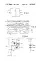
- FIG. 1schematically shows a typical environment in which the preferred embodiment of the invention is used.
- FIG. 2is a circuit diagram of a motor control starting circuit in accordance with the invention.
- FIG. 3is a wave form diagram illustrating operation of the circuitry of FIG. 2.
- FIG. 4is a partial isolated circuit diagram of a modification of FIG. 2.
- a single phase AC induction motorhas a main winding for running the motor, and a start or auxiliary winding for a capacitor start or capacitor start-run type motor and/or for starting the motor wherein the auxiliary winding is energized when starting the motor from rest and then disconnected at a given motor speed.
- the fields in the main and auxiliary windingsare phase shifted, for example by capacitance, inductance, resistance or the like, to establish a rotating magnetic field for starting and/or running torque.
- FIG. 1shows main winding 1 and auxiliary 2 of a single phase AC induction motor connectable through a switch 3 to an AC power source 4.
- Capacitor 5provides the phase shift for starting torque.
- switch 6is opened to disconnect auxiliary winding 2 from power source 4.
- FIG. 2shows circuitry in accordance with the invention for controlling disconnect switch 6.
- a main voltage detector circuit including diode 10is connected across main winding 1 for sensing the magnitude of the AC main winding voltage.
- An auxiliary voltage detector circuit including diode 12is connected across auxiliary winding 2 for sensing the magnitude of the AC auxiliary winding voltage.
- Main winding voltageis sensed through rectifying diodes 14 and 10 and resistors 16, 18, 20 and 28 and filtered by capacitors 22 and 24.
- the voltage at node 26is reduced by the voltage divider provided by resistor 16 on one side of the node and the parallel combination of resistor 28 and series resistors 18 and 20 on the other side of the node.
- the voltage at node 30is the voltage at node 26 less the drop across diode 10.
- the voltage at node 32is the voltage at node 30 reduced by the voltage divider provided by resistors 18 and 20.
- the voltages at nodes 30 and 32are derived from the AC line and provide reference voltages relative thereto for the cut-out comparator 61 and for the cut-in restart or comparator 62, to be described.
- cut-out and cut-in reference voltagesvary with the line voltage and thus provide compensation of same, and allow the cut-out speed and the cut-in restart speed of the motor to be relatively independent of line voltage.
- the cut-in restart voltage at node 32is less than the cut-out voltage at node 30.
- the auxiliary winding voltageis reduced by the voltage divider network provided by resistors 34 and 36 and sensed through half wave rectifying diode 12 and resistor 38 and filtered by capacitor 40.
- the sensed auxiliary winding voltage at node 42is supplied to both the cut-out comparator 61 and the cut-in restart comparator 62 for comparison against the respective floating main winding AC line reference voltages.
- a half wave rectified DC power supplyis provided from the AC source through diode 14 and resistors 44, 46 and 94 clamped by zener diode 48 and filtered by capacitor 50 to provide a fixed DC reference voltage at node 52, in this case 12 volts, for powering the control circuitry, to be described.
- the circuitry in FIG. 2utilizes a quad comparator chip, such as an LM339, wherein manufacturer designated pin number assignments are shown for clarity.
- First, second, third and fourth comparators on the chipare respectively shown at 61, 62, 63 and 64.
- the flip flop 21 in FIG. 4 of the noted Shemanske et al applicationis eliminated, and the flip flop function is provided by a hard wire connection between the comparators, to be described.
- the minus input at pin 10 of comparator 61is used as the reference input and is connected to node 30.
- the plus input at pin 11 of comparator 61is the comparing input and is connected to node 42.
- the output of comparator 61 at pin 13provides a turn-off signal by going high.
- Third comparator 63has a plus input at pin 7 which is used as the reference input and is connected through resistor 66 to the regulated DC supply at node 52.
- the minus input at pin 6 of comparator 63is the comparing input and receives the turn-off high signal from comparator 61 through diode 68, which high signal at pin 6 causes the output of comparator 63 at pin 1 to go low.
- Comparator 63compares the output of comparator 61 against the reference voltage from node 52 and outputs a low turn-off signal at pin 1 when the high turn-off signal at pin 6 rises in a given polarity direction to or above a predetermined value relative to the reference voltage at pin 7.
- the low turn-off signal at pin 1is supplied through resistor 70 to the fourth comparator 64 at pin 4 which is the minus input and is used as the comparing input for comparator 64.
- the plus input of comparator 64 at pin 5is the reference input and is connected with pin 7 of comparator 63 at a common node 72 and connected through resistor 66 to the regulated DC supply at node 52.
- output pin 1 of comparator 63goes low
- the input pin 4 of comparator 64likewise goes low
- in turn output pin 2 of comparator 64goes high which provides a turn-off signal to switch 6, which in turn disconnects auxiliary winding 2 from AC source 4, to be described.
- Voltage comparator 64compares at input pin 4 the output of comparator 63 against the reference voltage at pin 5 and outputs the high turn-off signal at pin 2 when the low turn-off signal from comparator 63 decreases in a given polarity direction to or below a predetermined value relative to the reference voltage at pin 5.
- Switch 6is an optically isolated triac driver, as know in the art, for example an MOC3023, and will be only briefly described.
- Triac 74is in series with capacitor 5 and auxiliary winding 2 across AC source 4, and has a gate circuit including a light responsive triac 76 for controlling conduction of triac 74.
- Triac terminal 78is connected to one plate of capacitor 5 and triac terminal 80 is connected to AC source 4.
- terminal 78is positive with respect to terminal 80, and triac 74 is conductive, current flows from terminal 78 through limiting resistors 82 and 84 and through triac 76 to the gate 86 of triac 74 to bias the latter into conduction such that starting current may flow through triac 74 between terminals 78 and 80.
- Capacitor 88 and resistor 82provide a snubber network for optotriac driver 76.
- Resistor 90provides gate stability.
- Light responsive triac 76is optically coupled to LED 92 and is activated by the latter to initiate conduction of triac 76 and in turn conduction of triac 74.
- output pin 2 of comparator 64goes low, a circuit is completed from the regulated DC supply at node 52 through LED 92 and resistor 96, whereby light is emitted from LED 92 to light responsive triac 76 to activate the latter.
- Initialization meansis provided by an RC timing circuit including capacitor 98 and resistor 100.
- a positive pulseis generated from node 52 through capacitor 98 and diode 102 to input pin 4 of comparator 64 causing the latter's output at pin 2 to go low which turns on LED 92 and triacs 76 and 74, hence connecting auxiliary winding 2 to AC power source 4 at initial energization of the motor.
- FIG. 3shows the AC line voltage across main winding 1 as appearing at node 104, and also shows the auxiliary winding voltage as appearing at node 106.
- FIG. 3also shows the filtered half wave rectified AC line cut-out reference voltage at node 30, the filtered half wave rectified AC line cut-in reference voltage at node 32, and the filtered half wave rectified auxiliary winding voltage at node 42.
- the filtered half wave rectified auxiliary winding voltage at node 42rises to the filtered half wave rectified AC line cut-out reference voltage at node 30, as shown at cross-over 108, and auxiliary winding 2 is disconnected from AC source 4 as above described.
- auxiliary winding 2is disconnected when the auxiliary winding voltage at node 42, including the components from AC source 4 and from rotationally induced voltage due to rotation of the rotor, increases to a predetermined cut-out value such as 108 relative to the main winding voltage at node 30.
- Restart or cut-in comparator 62senses rotationally induced voltage in the auxiliary winding during running of the motor after starting, i.e., after auxiliary winding 2 is disconnected from AC source 4. Cut-in or restart comparator 62 detects a given decrease in the induced auxiliary winding voltage, as at cut-in inverse cross-over 110, FIG.
- the low state at output pin 2 of comparator 64is also applied through resistor 116 to input pin 6 of comparator 63 to cause output pin 1 to go high, which high level is applied through resistor 70 to input pin 4 of comparator 64 to complete the flip flop or latching action and provide a latched condition.
- Resistor 118provides a voltage divider network with resistor 66 to provide a reduced voltage level at node 72.
- Resistors 120, 122 and 124provide pull-up resistors at the outputs of the respective comparators.
- FIG. 4shows a further application of the invention in a capacitor run motor with a run capacitor 130 connected between nodes 80 and 106 in series with auxiliary winding 2, where like reference numerals are used from FIG. 2 where appropriate to facilitate clarity.
- a higher voltage withstand capabilityis provided in the gate circuit of the power triac 74 by a pair of light responsive triacs 76a and 76b in series and optically triggered into conduction by respective LEDs 92a and 92b in series between resistors 94 and 96.
- Capacitor 88may be eliminated because of the presence of parallel capacitor 130 already in the circuit.
- Resistors 132 and 134equalize and share voltage spikes or transients to prevent unwanted dv/dt turn-on.
Landscapes
- Engineering & Computer Science (AREA)
- Power Engineering (AREA)
- Control Of Ac Motors In General (AREA)
Abstract
Description
Claims (8)
Priority Applications (1)
| Application Number | Priority Date | Filing Date | Title |
|---|---|---|---|
| US06/885,087US4670697A (en) | 1986-07-14 | 1986-07-14 | Low cost, load and speed sensitive motor control starting circuit |
Applications Claiming Priority (1)
| Application Number | Priority Date | Filing Date | Title |
|---|---|---|---|
| US06/885,087US4670697A (en) | 1986-07-14 | 1986-07-14 | Low cost, load and speed sensitive motor control starting circuit |
Publications (1)
| Publication Number | Publication Date |
|---|---|
| US4670697Atrue US4670697A (en) | 1987-06-02 |
Family
ID=25386108
Family Applications (1)
| Application Number | Title | Priority Date | Filing Date |
|---|---|---|---|
| US06/885,087Expired - Fee RelatedUS4670697A (en) | 1986-07-14 | 1986-07-14 | Low cost, load and speed sensitive motor control starting circuit |
Country Status (1)
| Country | Link |
|---|---|
| US (1) | US4670697A (en) |
Cited By (35)
| Publication number | Priority date | Publication date | Assignee | Title |
|---|---|---|---|---|
| US4719399A (en)* | 1986-09-24 | 1988-01-12 | Pt Components, Inc. | Quick discharge motor starting circuit |
| US4745347A (en)* | 1986-09-24 | 1988-05-17 | Pt Components, Inc. | Low cost instant reversing circuit |
| US4751450A (en)* | 1986-09-24 | 1988-06-14 | Pt Components, Inc. | Low cost, protective start from coast circuit |
| US4751449A (en)* | 1986-09-24 | 1988-06-14 | Pt Components, Inc. | Start from coast protective circuit |
| US4782278A (en)* | 1987-07-22 | 1988-11-01 | Pt Components, Inc. | Motor starting circuit with low cost comparator hysteresis |
| US4874974A (en)* | 1987-12-09 | 1989-10-17 | Wu Yao Yu | Motor with an auto output adjusting device |
| US4958118A (en)* | 1989-08-28 | 1990-09-18 | A. O. Smith Corporation | Wide range, self-starting single phase motor speed control |
| US4967131A (en)* | 1988-08-16 | 1990-10-30 | Kim In S | Electronic motor starter |
| US5017853A (en)* | 1990-02-27 | 1991-05-21 | Rexnord Corporation | Spikeless motor starting circuit |
| US5051681A (en)* | 1989-11-28 | 1991-09-24 | Empresa Brasileira De Compressores S/A Embarco | Electronic circuit for a single phase induction motor starting |
| US5235265A (en)* | 1992-01-27 | 1993-08-10 | Rexnord Corporation, Stearns Division | Multi-level motor load sensing circuit |
| US5296795A (en)* | 1992-10-26 | 1994-03-22 | Texas Instruments Incorporated | Method and apparatus for starting capacitive start, induction run and capacitive start, capacitive run electric motors |
| US5598080A (en)* | 1992-02-14 | 1997-01-28 | Grundfos A/S | Starting device for a single-phase induction motor |
| US5811955A (en)* | 1996-08-29 | 1998-09-22 | Flint & Walling Industries, Inc. | Electro-start motor switch |
| US5892349A (en)* | 1996-10-29 | 1999-04-06 | Therm-O-Disc, Incorporated | Control circuit for two speed motors |
| US6756756B1 (en) | 2002-10-04 | 2004-06-29 | Rexnard Corporation | Phase detector motor start switch |
| US20050007062A1 (en)* | 2003-07-09 | 2005-01-13 | Mehlhorn William L. | Switch assembly, electric machine having the switch assembly, and method of controlling the same |
| WO2006131937A2 (en) | 2005-06-09 | 2006-12-14 | Abhishek Singh | Switching system for controlling the starting of an electrical motor. |
| US20070035897A1 (en)* | 2005-07-29 | 2007-02-15 | Simon Jeffrey J | Motor protection inhibit circuit |
| EP1995205A1 (en)* | 2007-05-21 | 2008-11-26 | Müller Martini Holding AG | Hoisting gear with a single-phase electric motor |
| US8508374B1 (en) | 2003-09-29 | 2013-08-13 | Sje-Rhombus | Motor power module |
| US9328727B2 (en) | 2003-12-08 | 2016-05-03 | Pentair Water Pool And Spa, Inc. | Pump controller system and method |
| US9404500B2 (en) | 2004-08-26 | 2016-08-02 | Pentair Water Pool And Spa, Inc. | Control algorithm of variable speed pumping system |
| US9551344B2 (en) | 2004-08-26 | 2017-01-24 | Pentair Water Pool And Spa, Inc. | Anti-entrapment and anti-dead head function |
| US9556874B2 (en) | 2009-06-09 | 2017-01-31 | Pentair Flow Technologies, Llc | Method of controlling a pump and motor |
| US9568005B2 (en) | 2010-12-08 | 2017-02-14 | Pentair Water Pool And Spa, Inc. | Discharge vacuum relief valve for safety vacuum release system |
| US9726184B2 (en) | 2008-10-06 | 2017-08-08 | Pentair Water Pool And Spa, Inc. | Safety vacuum release system |
| US9777733B2 (en) | 2004-08-26 | 2017-10-03 | Pentair Water Pool And Spa, Inc. | Flow control |
| US9885360B2 (en) | 2012-10-25 | 2018-02-06 | Pentair Flow Technologies, Llc | Battery backup sump pump systems and methods |
| US9932984B2 (en) | 2004-08-26 | 2018-04-03 | Pentair Water Pool And Spa, Inc. | Pumping system with power optimization |
| US10240604B2 (en) | 2004-08-26 | 2019-03-26 | Pentair Water Pool And Spa, Inc. | Pumping system with housing and user interface |
| US10465676B2 (en) | 2011-11-01 | 2019-11-05 | Pentair Water Pool And Spa, Inc. | Flow locking system and method |
| US10731655B2 (en) | 2004-08-26 | 2020-08-04 | Pentair Water Pool And Spa, Inc. | Priming protection |
| US10871001B2 (en) | 2004-08-26 | 2020-12-22 | Pentair Water Pool And Spa, Inc. | Filter loading |
| US10947981B2 (en) | 2004-08-26 | 2021-03-16 | Pentair Water Pool And Spa, Inc. | Variable speed pumping system and method |
Citations (4)
| Publication number | Priority date | Publication date | Assignee | Title |
|---|---|---|---|---|
| US3421064A (en)* | 1966-03-25 | 1969-01-07 | Century Electric Co | Electric motor that deenergizes starting winding thereof when difference between voltages across running and starting windings thereof changes as rotor speed increases |
| US3671830A (en)* | 1970-06-24 | 1972-06-20 | Westinghouse Electric Corp | Single phase motor starting control apparatus |
| US3761792A (en)* | 1972-02-07 | 1973-09-25 | Franklin Electric Co Inc | Switching circuit for motor start winding |
| US3792324A (en)* | 1972-10-30 | 1974-02-12 | Reliance Electric Co | Single phase motor starting circuit |
- 1986
- 1986-07-14USUS06/885,087patent/US4670697A/ennot_activeExpired - Fee Related
Patent Citations (4)
| Publication number | Priority date | Publication date | Assignee | Title |
|---|---|---|---|---|
| US3421064A (en)* | 1966-03-25 | 1969-01-07 | Century Electric Co | Electric motor that deenergizes starting winding thereof when difference between voltages across running and starting windings thereof changes as rotor speed increases |
| US3671830A (en)* | 1970-06-24 | 1972-06-20 | Westinghouse Electric Corp | Single phase motor starting control apparatus |
| US3761792A (en)* | 1972-02-07 | 1973-09-25 | Franklin Electric Co Inc | Switching circuit for motor start winding |
| US3792324A (en)* | 1972-10-30 | 1974-02-12 | Reliance Electric Co | Single phase motor starting circuit |
Cited By (66)
| Publication number | Priority date | Publication date | Assignee | Title |
|---|---|---|---|---|
| US4719399A (en)* | 1986-09-24 | 1988-01-12 | Pt Components, Inc. | Quick discharge motor starting circuit |
| US4745347A (en)* | 1986-09-24 | 1988-05-17 | Pt Components, Inc. | Low cost instant reversing circuit |
| US4751450A (en)* | 1986-09-24 | 1988-06-14 | Pt Components, Inc. | Low cost, protective start from coast circuit |
| US4751449A (en)* | 1986-09-24 | 1988-06-14 | Pt Components, Inc. | Start from coast protective circuit |
| US4782278A (en)* | 1987-07-22 | 1988-11-01 | Pt Components, Inc. | Motor starting circuit with low cost comparator hysteresis |
| US4874974A (en)* | 1987-12-09 | 1989-10-17 | Wu Yao Yu | Motor with an auto output adjusting device |
| US4967131A (en)* | 1988-08-16 | 1990-10-30 | Kim In S | Electronic motor starter |
| US4958118A (en)* | 1989-08-28 | 1990-09-18 | A. O. Smith Corporation | Wide range, self-starting single phase motor speed control |
| US5051681A (en)* | 1989-11-28 | 1991-09-24 | Empresa Brasileira De Compressores S/A Embarco | Electronic circuit for a single phase induction motor starting |
| US5017853A (en)* | 1990-02-27 | 1991-05-21 | Rexnord Corporation | Spikeless motor starting circuit |
| US5235265A (en)* | 1992-01-27 | 1993-08-10 | Rexnord Corporation, Stearns Division | Multi-level motor load sensing circuit |
| US5598080A (en)* | 1992-02-14 | 1997-01-28 | Grundfos A/S | Starting device for a single-phase induction motor |
| US5296795A (en)* | 1992-10-26 | 1994-03-22 | Texas Instruments Incorporated | Method and apparatus for starting capacitive start, induction run and capacitive start, capacitive run electric motors |
| US5811955A (en)* | 1996-08-29 | 1998-09-22 | Flint & Walling Industries, Inc. | Electro-start motor switch |
| US5892349A (en)* | 1996-10-29 | 1999-04-06 | Therm-O-Disc, Incorporated | Control circuit for two speed motors |
| US6756756B1 (en) | 2002-10-04 | 2004-06-29 | Rexnard Corporation | Phase detector motor start switch |
| US20050007062A1 (en)* | 2003-07-09 | 2005-01-13 | Mehlhorn William L. | Switch assembly, electric machine having the switch assembly, and method of controlling the same |
| US20050158177A1 (en)* | 2003-07-09 | 2005-07-21 | A.O. Smith Corporation | Switch assembly, electric machine having the switch assembly, and method of controlling the same |
| US20050156557A1 (en)* | 2003-07-09 | 2005-07-21 | A. O. Smith Corporation | Switch assembly, electric machine having the switch assembly, and method of controlling the same |
| US6989649B2 (en) | 2003-07-09 | 2006-01-24 | A. O. Smith Corporation | Switch assembly, electric machine having the switch assembly, and method of controlling the same |
| US7042192B2 (en) | 2003-07-09 | 2006-05-09 | A.O. Smith Corporation | Switch assembly, electric machine having the switch assembly, and method of controlling the same |
| US7183741B2 (en) | 2003-07-09 | 2007-02-27 | A. O. Smith Corporation | Switch assembly, electric machine having the switch assembly, and method of controlling the same |
| US20070113647A1 (en)* | 2003-07-09 | 2007-05-24 | A.O. Smith Corporation | Switch assembly, electric machine having the switch assembly, and method of controlling the same |
| US7427844B2 (en) | 2003-07-09 | 2008-09-23 | A. O. Smith Corporation | Switch assembly, electric machine having the switch assembly, and method of controlling the same |
| US8508374B1 (en) | 2003-09-29 | 2013-08-13 | Sje-Rhombus | Motor power module |
| US9328727B2 (en) | 2003-12-08 | 2016-05-03 | Pentair Water Pool And Spa, Inc. | Pump controller system and method |
| US10642287B2 (en) | 2003-12-08 | 2020-05-05 | Pentair Water Pool And Spa, Inc. | Pump controller system and method |
| US10416690B2 (en) | 2003-12-08 | 2019-09-17 | Pentair Water Pool And Spa, Inc. | Pump controller system and method |
| US10409299B2 (en) | 2003-12-08 | 2019-09-10 | Pentair Water Pool And Spa, Inc. | Pump controller system and method |
| US10289129B2 (en) | 2003-12-08 | 2019-05-14 | Pentair Water Pool And Spa, Inc. | Pump controller system and method |
| US10241524B2 (en) | 2003-12-08 | 2019-03-26 | Pentair Water Pool And Spa, Inc. | Pump controller system and method |
| US9399992B2 (en) | 2003-12-08 | 2016-07-26 | Pentair Water Pool And Spa, Inc. | Pump controller system and method |
| US9371829B2 (en) | 2003-12-08 | 2016-06-21 | Pentair Water Pool And Spa, Inc. | Pump controller system and method |
| US10415569B2 (en) | 2004-08-26 | 2019-09-17 | Pentair Water Pool And Spa, Inc. | Flow control |
| US10240604B2 (en) | 2004-08-26 | 2019-03-26 | Pentair Water Pool And Spa, Inc. | Pumping system with housing and user interface |
| US9404500B2 (en) | 2004-08-26 | 2016-08-02 | Pentair Water Pool And Spa, Inc. | Control algorithm of variable speed pumping system |
| US9551344B2 (en) | 2004-08-26 | 2017-01-24 | Pentair Water Pool And Spa, Inc. | Anti-entrapment and anti-dead head function |
| US11391281B2 (en) | 2004-08-26 | 2022-07-19 | Pentair Water Pool And Spa, Inc. | Priming protection |
| US11073155B2 (en) | 2004-08-26 | 2021-07-27 | Pentair Water Pool And Spa, Inc. | Pumping system with power optimization |
| US9605680B2 (en) | 2004-08-26 | 2017-03-28 | Pentair Water Pool And Spa, Inc. | Control algorithm of variable speed pumping system |
| US10947981B2 (en) | 2004-08-26 | 2021-03-16 | Pentair Water Pool And Spa, Inc. | Variable speed pumping system and method |
| US9777733B2 (en) | 2004-08-26 | 2017-10-03 | Pentair Water Pool And Spa, Inc. | Flow control |
| US10871001B2 (en) | 2004-08-26 | 2020-12-22 | Pentair Water Pool And Spa, Inc. | Filter loading |
| US9932984B2 (en) | 2004-08-26 | 2018-04-03 | Pentair Water Pool And Spa, Inc. | Pumping system with power optimization |
| US10527042B2 (en) | 2004-08-26 | 2020-01-07 | Pentair Water Pool And Spa, Inc. | Speed control |
| US10240606B2 (en) | 2004-08-26 | 2019-03-26 | Pentair Water Pool And Spa, Inc. | Pumping system with two way communication |
| US10502203B2 (en) | 2004-08-26 | 2019-12-10 | Pentair Water Pool And Spa, Inc. | Speed control |
| US10480516B2 (en) | 2004-08-26 | 2019-11-19 | Pentair Water Pool And Spa, Inc. | Anti-entrapment and anti-deadhead function |
| US10871163B2 (en) | 2004-08-26 | 2020-12-22 | Pentair Water Pool And Spa, Inc. | Pumping system and method having an independent controller |
| US10731655B2 (en) | 2004-08-26 | 2020-08-04 | Pentair Water Pool And Spa, Inc. | Priming protection |
| WO2006131937A3 (en)* | 2005-06-09 | 2007-06-28 | Abhishek Singh | Switching system for controlling the starting of an electrical motor. |
| WO2006131937A2 (en) | 2005-06-09 | 2006-12-14 | Abhishek Singh | Switching system for controlling the starting of an electrical motor. |
| US20090128082A1 (en)* | 2005-06-09 | 2009-05-21 | Abhishek Singh | Switching system for controlling the starting of an electrical motor |
| US7652440B2 (en) | 2005-06-09 | 2010-01-26 | Abhishek Singh | Switching system for controlling the starting of an electrical motor |
| US7208909B2 (en)* | 2005-07-29 | 2007-04-24 | Rockwell Automation Technologies, Inc. | Motor protection inhibit circuit |
| US20070035897A1 (en)* | 2005-07-29 | 2007-02-15 | Simon Jeffrey J | Motor protection inhibit circuit |
| EP1995205A1 (en)* | 2007-05-21 | 2008-11-26 | Müller Martini Holding AG | Hoisting gear with a single-phase electric motor |
| US10724263B2 (en) | 2008-10-06 | 2020-07-28 | Pentair Water Pool And Spa, Inc. | Safety vacuum release system |
| US9726184B2 (en) | 2008-10-06 | 2017-08-08 | Pentair Water Pool And Spa, Inc. | Safety vacuum release system |
| US10590926B2 (en) | 2009-06-09 | 2020-03-17 | Pentair Flow Technologies, Llc | Method of controlling a pump and motor |
| US9556874B2 (en) | 2009-06-09 | 2017-01-31 | Pentair Flow Technologies, Llc | Method of controlling a pump and motor |
| US11493034B2 (en) | 2009-06-09 | 2022-11-08 | Pentair Flow Technologies, Llc | Method of controlling a pump and motor |
| US9568005B2 (en) | 2010-12-08 | 2017-02-14 | Pentair Water Pool And Spa, Inc. | Discharge vacuum relief valve for safety vacuum release system |
| US10465676B2 (en) | 2011-11-01 | 2019-11-05 | Pentair Water Pool And Spa, Inc. | Flow locking system and method |
| US10883489B2 (en) | 2011-11-01 | 2021-01-05 | Pentair Water Pool And Spa, Inc. | Flow locking system and method |
| US9885360B2 (en) | 2012-10-25 | 2018-02-06 | Pentair Flow Technologies, Llc | Battery backup sump pump systems and methods |
Similar Documents
| Publication | Publication Date | Title |
|---|---|---|
| US4670697A (en) | Low cost, load and speed sensitive motor control starting circuit | |
| US4782278A (en) | Motor starting circuit with low cost comparator hysteresis | |
| US5017853A (en) | Spikeless motor starting circuit | |
| US4622506A (en) | Load and speed sensitive motor starting circuit | |
| US4751450A (en) | Low cost, protective start from coast circuit | |
| US4719399A (en) | Quick discharge motor starting circuit | |
| US4604563A (en) | Electronic switch for starting AC motor | |
| US4786850A (en) | Motor starting circuit with time delay cut-out and restart | |
| KR930005880B1 (en) | Motor control circuit with automatic restart or cut-in. | |
| KR0140227B1 (en) | Electronic control circuits electronically commutated motor systems | |
| US4937731A (en) | Power supply with automatic input voltage doubling | |
| EP0356310B1 (en) | Electronic motor starter | |
| US4751449A (en) | Start from coast protective circuit | |
| US6181092B1 (en) | Current control circuit for a reluctance machine | |
| US5589753A (en) | Rate effect motor start circuit | |
| US5654620A (en) | Sensorless speed detection circuit and method for induction motors | |
| US4496895A (en) | Universal single phase motor starting control apparatus | |
| EP1240709A1 (en) | Time rate of change motor start circuit | |
| US4740734A (en) | Control apparatus for brushless dc motors | |
| CA1129496A (en) | Power supply and control circuit for series connected controller | |
| US4687982A (en) | Instant reversing circuit | |
| US4486700A (en) | Universal single phase motor starting control apparatus | |
| US6756756B1 (en) | Phase detector motor start switch | |
| US4745347A (en) | Low cost instant reversing circuit | |
| EP1176707B1 (en) | Voltage converter circuit with self oscillating half bridge configuration and with protection against hard switching |
Legal Events
| Date | Code | Title | Description |
|---|---|---|---|
| AS | Assignment | Owner name:PT COMPONENTS, INC., WILWAUKEE, WI, A CORP OF DE, Free format text:ASSIGNMENT OF ASSIGNORS INTEREST;ASSIGNORS:WREGE, RICHARD A.;CHMIEL, STEVEN F.;MURN, VICTOR A.;SIGNING DATES FROM 19860916 TO 19860923;REEL/FRAME:004608/0751 Owner name:PT COMPONENTS, INC., WILWAUKEE, WI, A CORP OF DE Free format text:ASSIGNMENT OF ASSIGNORS INTEREST.;ASSIGNORS:WREGE, RICHARD A.;CHMIEL, STEVEN F.;MURN, VICTOR A.;REEL/FRAME:004608/0751;SIGNING DATES FROM 19860916 TO 19860923 | |
| AS | Assignment | Owner name:WILMINGTON TRUST COMPANY, RODNEY SQUARE NORTH, WIL Free format text:SECURITY INTEREST;ASSIGNOR:PT COMPONENTS, INC.;REEL/FRAME:004932/0146 Effective date:19880816 | |
| FEPP | Fee payment procedure | Free format text:PAYOR NUMBER ASSIGNED (ORIGINAL EVENT CODE: ASPN); ENTITY STATUS OF PATENT OWNER: LARGE ENTITY | |
| FPAY | Fee payment | Year of fee payment:4 | |
| AS | Assignment | Owner name:REXNORD CORPORATION, A CORP. OF DE Free format text:MERGER;ASSIGNOR:PT COMPONENTS INC., A CORP. OF DE;REEL/FRAME:006149/0608 Effective date:19920512 | |
| AS | Assignment | Owner name:WILMINGTON TRUST COMPANY A DE CORP., DELAWARE Free format text:SECURITY INTEREST;ASSIGNOR:REXNORD CORPORATION A DE CORP.;REEL/FRAME:006188/0942 Effective date:19920709 Owner name:WADE, WILLIAM J., DELAWARE Free format text:SECURITY INTEREST;ASSIGNOR:REXNORD CORPORATION A DE CORP.;REEL/FRAME:006188/0942 Effective date:19920709 | |
| AS | Assignment | Owner name:REXNORD CORPORATION, A DE CORP., STATELESS Free format text:MERGER;ASSIGNORS:REXNORD CORPORATION, A DE CORP.;REX-PT HOLDINGS, INC., A CORP. OF DE;REEL/FRAME:006253/0090 Effective date:19920707 | |
| REMI | Maintenance fee reminder mailed | ||
| LAPS | Lapse for failure to pay maintenance fees | ||
| FP | Lapsed due to failure to pay maintenance fee | Effective date:19950607 | |
| STCH | Information on status: patent discontinuation | Free format text:PATENT EXPIRED DUE TO NONPAYMENT OF MAINTENANCE FEES UNDER 37 CFR 1.362 |