US4667682A - Cardiac ambulatory monitor - Google Patents
Cardiac ambulatory monitorDownload PDFInfo
- Publication number
- US4667682A US4667682AUS06/751,016US75101685AUS4667682AUS 4667682 AUS4667682 AUS 4667682AUS 75101685 AUS75101685 AUS 75101685AUS 4667682 AUS4667682 AUS 4667682A
- Authority
- US
- United States
- Prior art keywords
- counter
- time
- accumulator
- pulse
- preset
- Prior art date
- Legal status (The legal status is an assumption and is not a legal conclusion. Google has not performed a legal analysis and makes no representation as to the accuracy of the status listed.)
- Expired - Fee Related
Links
- 230000000747cardiac effectEffects0.000titleclaimsdescription8
- 208000001871TachycardiaDiseases0.000claimsabstractdescription22
- 230000006794tachycardiaEffects0.000claimsabstractdescription22
- 208000006218bradycardiaDiseases0.000claimsabstractdescription21
- 230000036471bradycardiaEffects0.000claimsabstractdescription21
- 206010003119arrhythmiaDiseases0.000claimsabstractdescription10
- 230000006793arrhythmiaEffects0.000claimsabstractdescription10
- 238000001514detection methodMethods0.000claimsabstractdescription4
- 238000000718qrs complexMethods0.000claimsdescription7
- 230000033764rhythmic processEffects0.000claimsdescription3
- 238000001914filtrationMethods0.000claims2
- 230000003213activating effectEffects0.000claims1
- 230000004913activationEffects0.000abstractdescription2
- 230000008859changeEffects0.000description3
- 239000003990capacitorSubstances0.000description2
- 238000012544monitoring processMethods0.000description2
- 230000003321amplificationEffects0.000description1
- 230000007812deficiencyEffects0.000description1
- 238000010586diagramMethods0.000description1
- 230000009977dual effectEffects0.000description1
- 230000000977initiatory effectEffects0.000description1
- 238000012806monitoring deviceMethods0.000description1
- 238000003199nucleic acid amplification methodMethods0.000description1
- 230000037081physical activityEffects0.000description1
- 230000004044responseEffects0.000description1
- 238000001228spectrumMethods0.000description1
Images
Classifications
- A—HUMAN NECESSITIES
- A61—MEDICAL OR VETERINARY SCIENCE; HYGIENE
- A61B—DIAGNOSIS; SURGERY; IDENTIFICATION
- A61B5/00—Measuring for diagnostic purposes; Identification of persons
- A61B5/24—Detecting, measuring or recording bioelectric or biomagnetic signals of the body or parts thereof
- A61B5/316—Modalities, i.e. specific diagnostic methods
- A61B5/318—Heart-related electrical modalities, e.g. electrocardiography [ECG]
- A61B5/346—Analysis of electrocardiograms
- A61B5/349—Detecting specific parameters of the electrocardiograph cycle
- A61B5/363—Detecting tachycardia or bradycardia
- A—HUMAN NECESSITIES
- A61—MEDICAL OR VETERINARY SCIENCE; HYGIENE
- A61B—DIAGNOSIS; SURGERY; IDENTIFICATION
- A61B5/00—Measuring for diagnostic purposes; Identification of persons
- A61B5/24—Detecting, measuring or recording bioelectric or biomagnetic signals of the body or parts thereof
- A61B5/316—Modalities, i.e. specific diagnostic methods
- A61B5/318—Heart-related electrical modalities, e.g. electrocardiography [ECG]
- A61B5/333—Recording apparatus specially adapted therefor
- A61B5/336—Magnetic recording apparatus
Definitions
- the present inventionis directed toward a heart monitoring device and more particularly toward such a device which is intended to be carried by a patient and which detects arrhythmias and records the patient's ECG in response thereto.
- Cardiac monitoring apparatuseswhich detect arryhthmias have been known for many years. These are described, for example, in U.S. Pat. Nos. 3,144,019; 3,552,386; 3,587,563; 3,608,545; 3,823,708; 3,824,990; 3,881,467; 4,231,374; 4,261,370 and 4,457,315. It is known that the detection of two particular arrhythmias, tachycardia or high heartbeat rate and bradycardia or low heartbeat rate, are useful in providing information to a physician concerning the general condition of a patient's heart. Many of the foregoing patents describe systems for detecting tachycardia and/or bradycardia.
- the present inventionis designed to overcome the deficiencies of the prior art described above to provide a highly reliable and inexpensive cardiac ambulatory monitor.
- the ambulatory arrhythmia detection and ECG recorder of the present inventionsenses both tachycardia and bradycardia conditions and activates a tape recorder to record the ECG for a period of 15 seconds after an arrhythmia is detected.
- Tachycardia and bradycardia conditionsare sensed by converting the QRS component signals of the ECG into a pulse train which is a real time representation of the patient's actual heartbeat and then measuring the time between pulses utilizing two different oscillator controlled counter circuits.
- the first circuitindicates a tachycardia condition if the time between pulses is less the 500 milliseconds (120 beats per minute) or some other time preset by a doctor and the second circuit indicates a bradycardia condition if the time between pulses is greater than 1200 milliseconds (50 beats per minute) or some other time preset by a doctor.
- the recordermay also record the ECG waveform for 15 seconds upon a manual activation thereof and at preset intervals such as every half hour or hour in accordance with a preset program.
- FIG. 1is a schematic representation shown primarily in block form of a cardiac ambulatory monitor constructed in accordance with the principles of the present invention
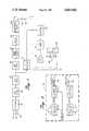
- FIG. 2is a schematic diagram showing the tachycardia and bradycardia condition sensing circuits of FIG. 1.
- FIG. 1an overall schematic view primarily in block form of an ambulatory heart monitor constructed in accordance with the principles of the present invention and designated generally as 10.
- the monitor 10is intended to be battery operated and relatively compact and light so that it can be carried by a patient in a pocket or attached to the patient's belt or the like.
- Three electrodes 12, 14 and 16are adapted to be positioned on a patient's body. Preferably, they are arranged in what is commonly referred to as a "Marquette arrangement" wherein the positive electrode is positioned over the heart, the ground electrode is positioned over the left shoulder and the negative electrode is positioned over the right shoulder.
- the three electrodesdevelop an electrical signal which is indicative of the patient's cardiac rhythm as is well known in the art.
- the three electrodesare connected to an input amplifier 18 which is a dual differential amplifier producing a single ended amplified signal of the cardiac rhythm. In the preferred embodiment, amplifier 18 has an amplification factor of approximately 10 times.
- the output of amplifier 18is fed to high-pass filter 20 which filters out the low frequency base line drift due to physical activity which results from impedance mismatching between the three electrode leads.
- the output of high-pass filter 20is then fed to the low-pass filter 22 which removes artifacts above the frequency range of approximately 125 Hz.
- Tape recorder 26is preferably of the micro or mini cassette type and may either be built directly into the same housing which carries the remaining components of the ambulatory heart monitor 10 or it may be a separate cassette recorder which is also carried by the patient.
- the frequency modulated ECG signalis constantly applied to the audio input terminal of the tape recorder 26.
- the tape recorder driveis only activated for 15-second intervals at selected times or when certain conditions are met. Accordingly, the frequency modulated ECG signal is only recorded during these 15-second intervals.
- the output of low-pass filter 22is also fed into band-pass filter 28 which removes the P and T waves from the ECG leaving only the QRS complex which is between approximately 5 Hz and 40 Hz. Thereafter, the signal is fed to single-ended differentiator 30 which differentiates the QRS complex leaving a waveform representing the true frequency components of the QRS signal.
- the output of differentiator 30is fed into pulse generator 32 which is essentially a voltage detector which produces a positive voltage pulse which falls in the frequency spectrum of the QRS frequency levels. Therefore, the output from the pulse generator 32 is a digital pulse whose analog relationship is effectively centered around the frequency components of the QRS complex. In other words, pulse generator 32 generates a pulse train in real time relationship with the ECG wherein each pulse represents the actual occurrence of a QRS complex and, thus, a different heartbeat.
- the pulse train from pulse generator 32is fed to the tachycardia and bradycardia condition sensing circuit 34, the details of which will be described more fully hereinafter.
- a normal heart rateis approximately 80 beats per minute. If circuit 34 senses the pulse train from pulse generator 32 to be well in excess of 80 beats per minute, for example, above 120 beats per minute, a first control signal indicating a tachycardia condition will appear on tachycardia output 36 of circuit 34. Similarly, if circuit 34 senses that the pulse train from pulse generator 32 is considerably below the normal heart rate, for example, below 50 beats per minute, a bradycardia condition control signal will appear on bradycardia output 38 of circuit 34.
- the tachycardia control output 36 and bradycardia control output 38 of circuit 34are connected to different control inputs of OR gate 40.
- OR gate 40will conduct initiating the 15-second timer 42.
- Timer 42will activate the drive circuit of the tape recorder 26 so that the tape recorder will now record the actual ECG for the 15 seconds next following the occurrence of a control signal to the OR gate 40. Thereafter, the timer 42 will automatically deactivate tape recorder 26.
- the OR gate 40which in combination with the timer 42 functions as the recorder controller, has two other control inputs. One of these control inputs is connected to a manually operable momentary contact push button switch 44. Should the patient believe that he has sensed an arrhythmia or should he merely wish to test the device, he simply depresses switch 44 whereby the recorder controller OR gate 40 and timer 42 will activate the tape recorder 26 for 15 seconds.
- interval timer 46is also connected to one of the control inputs of the OR gate 40.
- Interval timer 46has a plurality of selectable outputs and generates a pulse every 15 minutes, 30 minutes, 60 minutes or 120 minutes depending on which output is selected by interval selector switch 48.
- interval selector switch 48if the physician places interval selector switch 48 at 30 minutes, for example, the tape recorder 26 will record the ECG every 30 minutes during the day. Each recording will, of course, be 15 seconds long as determined by the timer 42.
- the tachycardia and bradycardia condition determining circuit 34will now be described in further detail with reference to FIG. 2.
- the upper portion of FIG. 2is utilized to determine a tachycardia condition whereas the lower portion of the circuit of FIG. 2 determines a bradycardia condition.
- the tachycardia condition sensing circuitincludes a first oscillator controlled counter 50 which counts at a first predetermined rate. As is known in the art, the counting rate will be determined by the value of the resistor R1 and capacitor C1. The oscillator counter 50 will count to a predetermined number and generates a first output signal each time it reaches the predetermined number. The pulse train from pulse generator 32 is connected to the reset input of the oscillator counter 50 so that the counter is reset upon the receipt of each pulse from the pulse generator 32.
- the output signal from the oscillator counter 50is connected to the reset of a first counter accumulator 52.
- the accumulator 52also has a clock input which is connected to the output of pulse generator 32.
- the counter accumulator 52is incremented by one.
- a control signalis generated at the output of accumulator 52, i.e. on line 36, whenever the accumulator is incremented to a first preset number.
- the accumulator 52will be incremented past one only if the time between the pulses from pulse generator 32 is less than the time it takes for the oscillator counter 50 to reach the predetermined number to which it is to count. Otherwise, the counter 50 will reset the accumulator 52 to zero before it can be incremented to two.
- a tachycardia conditionis determined by the physician to be a heartbeat rate of above 120 beats per minute, then the predetermined number to which the counter 50 is to count and the rate at which it is to count are set so that the counter 50 reaches the predetermined number in 500 milliseconds which is equivalent to 120 beats per minute.
- the counter 50be a multistage counter and that the oscillator have a frequency of approximately 31,000 cycles per second. In this case, the first predetermined number to which the counter 50 must count in order to generate an output signal would be approximately 15,500.
- either the frequency rate or predetermined number or bothbe manually adjustable by the physician so that a tachycardia condition can be set to be above or below 120 beats per minute as desired. This can be accomplished by making R1 and/or C1 variable or by providing means for allowing the physician to change the taps on the multistage counter.
- the counter accumulator 52can be preset to generate a control signal each time a pair of pulses from the pulse generator 32 occur in less than the 500 milliseconds or other predetermined time, it is preferred that the accumulator 52 must be incremented to a higher preset number such as four in order to avoid errors. It is not uncommon, even with normal heartbeat rates, for there to occasionally be a pair of pulses having a time duration between them of less than 500 milliseconds. With the accumulator 52 set at four, four pulses in a row having a time duration between them of less than 500 milliseconds must occur before a tachycardia control signal is generated. Preferably, the preset number in accumulator 52 will be able to be varied by the physician.
- the bradycardia condition sensing circuit shown in FIG. 2includes a second oscillator controlled counter 54.
- Oscillator control counter 54is similar to counter 50 and preferably also counts to approximately 15,500.
- Resistor R2 and capacitor C2are selected so that the counter 54 counts to the second predetermined number (approximately 15,500) at a second predetermined rate of approximately 13,000 counts per second. This is the equivalent of a heartbeat rate of approximately 50 beats per minute or a time duration between beats of approximately 1200 milliseconds.
- the reset input to the oscillator counter 54is also connected to the pulse generator 32 so that the same is reset to zero each time a pulse is received from the pulse generator 32.
- the oscillator counter 54generates a second output signal each time it counts out without being reset and applies this second output signal to the clock input of a second counter accumulator 56.
- the oscillator counter 54will only reach its full count and thereby increment counter accumulator 56 if the pulse rate from the pulse train generated by pulse generator 32 is less than 50 beats per minute, i.e. a time duration between pulses of greater than 1200 milliseconds.
- the counter accumulator 56is preset so that a second control signal is generated on control line 38 only if the accumulator is incremented to a preselected second preset number such as eight.
- the second oscillator counter 54 and the second counter accumulator 56are variable so that the physician can change the pulse rate which will be considered to be a bradycardia condition and can change the number of second output signals from the oscillator counter 54 which are needed in order to increment the counter accumulator 56 to generate a bradycardia control signal.
Landscapes
- Health & Medical Sciences (AREA)
- Life Sciences & Earth Sciences (AREA)
- Cardiology (AREA)
- Heart & Thoracic Surgery (AREA)
- Molecular Biology (AREA)
- Pathology (AREA)
- Engineering & Computer Science (AREA)
- Biomedical Technology (AREA)
- Physics & Mathematics (AREA)
- Medical Informatics (AREA)
- Biophysics (AREA)
- Surgery (AREA)
- Animal Behavior & Ethology (AREA)
- General Health & Medical Sciences (AREA)
- Public Health (AREA)
- Veterinary Medicine (AREA)
- Measurement And Recording Of Electrical Phenomena And Electrical Characteristics Of The Living Body (AREA)
- Measuring Pulse, Heart Rate, Blood Pressure Or Blood Flow (AREA)
Abstract
Description
Claims (13)
Priority Applications (1)
| Application Number | Priority Date | Filing Date | Title |
|---|---|---|---|
| US06/751,016US4667682A (en) | 1985-07-02 | 1985-07-02 | Cardiac ambulatory monitor |
Applications Claiming Priority (1)
| Application Number | Priority Date | Filing Date | Title |
|---|---|---|---|
| US06/751,016US4667682A (en) | 1985-07-02 | 1985-07-02 | Cardiac ambulatory monitor |
Publications (1)
| Publication Number | Publication Date |
|---|---|
| US4667682Atrue US4667682A (en) | 1987-05-26 |
Family
ID=25020118
Family Applications (1)
| Application Number | Title | Priority Date | Filing Date |
|---|---|---|---|
| US06/751,016Expired - Fee RelatedUS4667682A (en) | 1985-07-02 | 1985-07-02 | Cardiac ambulatory monitor |
Country Status (1)
| Country | Link |
|---|---|
| US (1) | US4667682A (en) |
Cited By (27)
| Publication number | Priority date | Publication date | Assignee | Title |
|---|---|---|---|---|
| US4794532A (en)* | 1986-11-10 | 1988-12-27 | Hewlett-Packard Company | Virtual arrhythmia system |
| US4958641A (en)* | 1989-03-10 | 1990-09-25 | Instromedix, Inc. | Heart data monitoring method and apparatus |
| US5012814A (en)* | 1989-11-09 | 1991-05-07 | Instromedix, Inc. | Implantable-defibrillator pulse detection-triggered ECG monitoring method and apparatus |
| EP0463698A1 (en)* | 1990-06-29 | 1992-01-02 | Koninklijke Philips Electronics N.V. | QRS filter for NMR imaging apparatus and NMR imaging employing such filter |
| EP0450341A3 (en)* | 1990-04-05 | 1992-09-23 | Hewlett-Packard Company | Cardiac analyzer with rem sleep detection |
| EP0552009A1 (en)* | 1992-01-13 | 1993-07-21 | Oxford Medical Limited | ECG analyser |
| US5309920A (en)* | 1991-11-12 | 1994-05-10 | Stuart Medical Inc. | Ambulatory electrocardiographic patient monitoring system and method therefor |
| US5655540A (en)* | 1995-04-06 | 1997-08-12 | Seegobin; Ronald D. | Noninvasive method for identifying coronary artery disease utilizing electrocardiography derived data |
| US5683423A (en)* | 1996-03-14 | 1997-11-04 | Hewlett-Packard Company | Defibrillator and method for storing selected segments of audio data |
| US5738104A (en)* | 1995-11-08 | 1998-04-14 | Salutron, Inc. | EKG based heart rate monitor |
| US5857977A (en)* | 1996-08-08 | 1999-01-12 | The Regents Of The University Of Michigan | Method and apparatus for separation of ventricular tachycardia from ventricular fibrillation for implantable cardioverter defibrillators |
| US5954664A (en)* | 1995-04-06 | 1999-09-21 | Seegobin; Ronald D. | Noninvasive system and method for identifying coronary disfunction utilizing electrocardiography derived data |
| US6014578A (en)* | 1998-08-06 | 2000-01-11 | Meotronic, Inc. | Ambulatory recorder having method of configuring size of data subject to loss in volatile memory |
| US6077223A (en)* | 1998-08-06 | 2000-06-20 | Medtronic, Inc. | Ambulatory recorder having control screen to present dual interface for dual users |
| US6115622A (en)* | 1998-08-06 | 2000-09-05 | Medtronic, Inc. | Ambulatory recorder having enhanced sampling technique |
| US6119029A (en)* | 1998-08-06 | 2000-09-12 | Medtronic, Inc. | Ambulatory recorder having splash resistant sensor ports |
| US6128520A (en)* | 1998-08-06 | 2000-10-03 | Medtronic, Inc. | Ambulatory recorder having volatile and non-volatile memories |
| US6141574A (en)* | 1998-08-06 | 2000-10-31 | Medtronic, Inc. | Ambulatory recorder having sliding period switches |
| US6142938A (en)* | 1998-08-06 | 2000-11-07 | Medtronic Inc. | Ambulatory data recorder having ergonomically shaped housing |
| US6154668A (en)* | 1998-08-06 | 2000-11-28 | Medtronics Inc. | Ambulatory recorder having a real time and non-real time processors |
| US6200264B1 (en) | 1998-08-06 | 2001-03-13 | Medtronic Inc. | Ambulatory recorder having wireless data transfer with a multi-plane lens |
| US6245013B1 (en) | 1998-12-14 | 2001-06-12 | Medtronic, Inc. | Ambulatory recorder having synchronized communication between two processors |
| US6370423B1 (en) | 1998-10-05 | 2002-04-09 | Juan R. Guerrero | Method for analysis of biological voltage signals |
| US20070179734A1 (en)* | 2005-09-28 | 2007-08-02 | Chmiel Alan J | Transfer function control for biometric monitoring system and related method |
| US20090018457A1 (en)* | 2007-07-11 | 2009-01-15 | Chin-Yeh Hung | Clip-type monitoring device for wirelessly transmitting the heart rate |
| US20090171163A1 (en)* | 2007-12-31 | 2009-07-02 | Mates John W | Modular medical devices |
| EP1722680B1 (en)* | 2004-02-17 | 2013-04-10 | CardioNet, Inc. | Distributed cardiac activity monitoring with selective filtering |
Citations (10)
| Publication number | Priority date | Publication date | Assignee | Title |
|---|---|---|---|---|
| US3513833A (en)* | 1967-03-17 | 1970-05-26 | Birtcher Corp | Medical monitoring system |
| US3648689A (en)* | 1968-09-05 | 1972-03-14 | Burdick Corp | Cardiac monitoring apparatus for a plurality of patients |
| US3650263A (en)* | 1969-11-03 | 1972-03-21 | Marquette Electronics Inc | Monitoring system |
| US3773038A (en)* | 1972-04-07 | 1973-11-20 | Nasa | Digital computing cardiotachometer |
| US3858574A (en)* | 1972-11-03 | 1975-01-07 | Robert E Page | Pulse rate and amplitude monitor |
| US3978856A (en)* | 1975-03-20 | 1976-09-07 | Michel Walter A | Heart beat waveform monitoring apparatus |
| US4022192A (en)* | 1974-10-21 | 1977-05-10 | Laukien Gunther R | Apparatus for measuring the frequency of cardiac pulses |
| US4034745A (en)* | 1976-03-15 | 1977-07-12 | Bloom Kenneth A | Cardiotachometer |
| US4083366A (en)* | 1976-06-16 | 1978-04-11 | Peter P. Gombrich | Heart beat rate monitor |
| US4184487A (en)* | 1977-04-18 | 1980-01-22 | U.S. Philips Corporation | Electrocardiograph |
- 1985
- 1985-07-02USUS06/751,016patent/US4667682A/ennot_activeExpired - Fee Related
Patent Citations (10)
| Publication number | Priority date | Publication date | Assignee | Title |
|---|---|---|---|---|
| US3513833A (en)* | 1967-03-17 | 1970-05-26 | Birtcher Corp | Medical monitoring system |
| US3648689A (en)* | 1968-09-05 | 1972-03-14 | Burdick Corp | Cardiac monitoring apparatus for a plurality of patients |
| US3650263A (en)* | 1969-11-03 | 1972-03-21 | Marquette Electronics Inc | Monitoring system |
| US3773038A (en)* | 1972-04-07 | 1973-11-20 | Nasa | Digital computing cardiotachometer |
| US3858574A (en)* | 1972-11-03 | 1975-01-07 | Robert E Page | Pulse rate and amplitude monitor |
| US4022192A (en)* | 1974-10-21 | 1977-05-10 | Laukien Gunther R | Apparatus for measuring the frequency of cardiac pulses |
| US3978856A (en)* | 1975-03-20 | 1976-09-07 | Michel Walter A | Heart beat waveform monitoring apparatus |
| US4034745A (en)* | 1976-03-15 | 1977-07-12 | Bloom Kenneth A | Cardiotachometer |
| US4083366A (en)* | 1976-06-16 | 1978-04-11 | Peter P. Gombrich | Heart beat rate monitor |
| US4184487A (en)* | 1977-04-18 | 1980-01-22 | U.S. Philips Corporation | Electrocardiograph |
Cited By (33)
| Publication number | Priority date | Publication date | Assignee | Title |
|---|---|---|---|---|
| US4794532A (en)* | 1986-11-10 | 1988-12-27 | Hewlett-Packard Company | Virtual arrhythmia system |
| US4958641A (en)* | 1989-03-10 | 1990-09-25 | Instromedix, Inc. | Heart data monitoring method and apparatus |
| US5012814A (en)* | 1989-11-09 | 1991-05-07 | Instromedix, Inc. | Implantable-defibrillator pulse detection-triggered ECG monitoring method and apparatus |
| EP0450341A3 (en)* | 1990-04-05 | 1992-09-23 | Hewlett-Packard Company | Cardiac analyzer with rem sleep detection |
| EP0463698A1 (en)* | 1990-06-29 | 1992-01-02 | Koninklijke Philips Electronics N.V. | QRS filter for NMR imaging apparatus and NMR imaging employing such filter |
| US5309920A (en)* | 1991-11-12 | 1994-05-10 | Stuart Medical Inc. | Ambulatory electrocardiographic patient monitoring system and method therefor |
| US5568814A (en)* | 1991-11-12 | 1996-10-29 | Protocol Systems, Inc. | Ambulatory patient monitoring system |
| EP0552009A1 (en)* | 1992-01-13 | 1993-07-21 | Oxford Medical Limited | ECG analyser |
| US5355891A (en)* | 1992-01-13 | 1994-10-18 | Oxford Medical Limited | ECG analyzer |
| US5655540A (en)* | 1995-04-06 | 1997-08-12 | Seegobin; Ronald D. | Noninvasive method for identifying coronary artery disease utilizing electrocardiography derived data |
| US5954664A (en)* | 1995-04-06 | 1999-09-21 | Seegobin; Ronald D. | Noninvasive system and method for identifying coronary disfunction utilizing electrocardiography derived data |
| US5738104A (en)* | 1995-11-08 | 1998-04-14 | Salutron, Inc. | EKG based heart rate monitor |
| US5876350A (en)* | 1995-11-08 | 1999-03-02 | Salutron, Inc. | EKG based heart rate monitor with digital filter and enhancement signal processor |
| US5683423A (en)* | 1996-03-14 | 1997-11-04 | Hewlett-Packard Company | Defibrillator and method for storing selected segments of audio data |
| US5857977A (en)* | 1996-08-08 | 1999-01-12 | The Regents Of The University Of Michigan | Method and apparatus for separation of ventricular tachycardia from ventricular fibrillation for implantable cardioverter defibrillators |
| US6077223A (en)* | 1998-08-06 | 2000-06-20 | Medtronic, Inc. | Ambulatory recorder having control screen to present dual interface for dual users |
| US6115622A (en)* | 1998-08-06 | 2000-09-05 | Medtronic, Inc. | Ambulatory recorder having enhanced sampling technique |
| US6119029A (en)* | 1998-08-06 | 2000-09-12 | Medtronic, Inc. | Ambulatory recorder having splash resistant sensor ports |
| US6128520A (en)* | 1998-08-06 | 2000-10-03 | Medtronic, Inc. | Ambulatory recorder having volatile and non-volatile memories |
| US6141574A (en)* | 1998-08-06 | 2000-10-31 | Medtronic, Inc. | Ambulatory recorder having sliding period switches |
| US6142938A (en)* | 1998-08-06 | 2000-11-07 | Medtronic Inc. | Ambulatory data recorder having ergonomically shaped housing |
| US6154668A (en)* | 1998-08-06 | 2000-11-28 | Medtronics Inc. | Ambulatory recorder having a real time and non-real time processors |
| US6200264B1 (en) | 1998-08-06 | 2001-03-13 | Medtronic Inc. | Ambulatory recorder having wireless data transfer with a multi-plane lens |
| US6014578A (en)* | 1998-08-06 | 2000-01-11 | Meotronic, Inc. | Ambulatory recorder having method of configuring size of data subject to loss in volatile memory |
| US20060206033A1 (en)* | 1998-10-05 | 2006-09-14 | Guerrero Juan R | System for analysis of biological voltage signals |
| US6370423B1 (en) | 1998-10-05 | 2002-04-09 | Juan R. Guerrero | Method for analysis of biological voltage signals |
| US20040059203A1 (en)* | 1998-10-05 | 2004-03-25 | Guerrero Juan R. | Method and system for analysis of biological signals such as dynamic electrocardiograms and the like |
| US6245013B1 (en) | 1998-12-14 | 2001-06-12 | Medtronic, Inc. | Ambulatory recorder having synchronized communication between two processors |
| EP1722680B1 (en)* | 2004-02-17 | 2013-04-10 | CardioNet, Inc. | Distributed cardiac activity monitoring with selective filtering |
| US20070179734A1 (en)* | 2005-09-28 | 2007-08-02 | Chmiel Alan J | Transfer function control for biometric monitoring system and related method |
| US8951190B2 (en)* | 2005-09-28 | 2015-02-10 | Zin Technologies, Inc. | Transfer function control for biometric monitoring system |
| US20090018457A1 (en)* | 2007-07-11 | 2009-01-15 | Chin-Yeh Hung | Clip-type monitoring device for wirelessly transmitting the heart rate |
| US20090171163A1 (en)* | 2007-12-31 | 2009-07-02 | Mates John W | Modular medical devices |
Similar Documents
| Publication | Publication Date | Title |
|---|---|---|
| US4667682A (en) | Cardiac ambulatory monitor | |
| US4457315A (en) | Cardiac arrhythmia detection and recording | |
| US5012814A (en) | Implantable-defibrillator pulse detection-triggered ECG monitoring method and apparatus | |
| US4248244A (en) | Method for measuring heart beat rate and circuit means for same | |
| US3698386A (en) | Cardiac rhythm computer device | |
| US4527567A (en) | Method and apparatus for automatically evaluating the quality of the performance of a cardiac pacing system | |
| US3780727A (en) | Cardiac pacer monitoring means with rate and pulse discrimination | |
| US6871089B2 (en) | Portable ECG monitor and method for atrial fibrillation detection | |
| US5228450A (en) | Methods and apparatus for ambulatory physiological monitoring | |
| US4151513A (en) | Apparatus for sensing and transmitting a pacemaker's stimulating pulse | |
| US3144019A (en) | Cardiac monitoring device | |
| US4807643A (en) | Digital electroneurometer | |
| US4202340A (en) | Method and apparatus for monitoring heart activity, detecting abnormalities, and cardioverting a malfunctioning heart | |
| US4628939A (en) | Method and improved apparatus for analyzing heart activity | |
| US4184493A (en) | Circuit for monitoring a heart and for effecting cardioversion of a needy heart | |
| US3734086A (en) | Equipment for measuring and displaying the time lapse between a given heartbeat and the corresponding arterial pulse | |
| US3552386A (en) | Arrhythmia detecting apparatus and method | |
| US3986496A (en) | Apparatus for sensing and transmitting a pacemaker's stimulating pulse | |
| US3602222A (en) | Rate meter, particularly a beat-by-beat cardiotachometer | |
| US3633569A (en) | Arrhythmia counter | |
| CA1087691A (en) | Fibrillation monitor and defibrillator | |
| US3910258A (en) | Cerebral activity monitor | |
| US3646931A (en) | Portable battery-powered instrument for visualizing the peripheral pulse waveform and pulse rate | |
| US3605727A (en) | Apparatus and method of monitoring and evaluating electrocardiac traces | |
| US3554188A (en) | Heartbeat frequency monitor |
Legal Events
| Date | Code | Title | Description |
|---|---|---|---|
| AS | Assignment | Owner name:CRATIVE MEDICAL SUPPLY COMPANY, INC. 725 NORTH BLA Free format text:ASSIGNMENT OF ASSIGNORS INTEREST.;ASSIGNOR:IHLENFELD, WILLIAM III;REEL/FRAME:004429/0296 Effective date:19850715 | |
| AS | Assignment | Owner name:MJ & E CORPORATION Free format text:CHANGE OF NAME;ASSIGNOR:CREATIVE MEDICAL SUPPLY COMPANY, INC.,;REEL/FRAME:004653/0501 Effective date:19850801 Owner name:CREATIVE MEDICAL SYSTEMS, INC., Free format text:CHANGE OF NAME;ASSIGNOR:GIG CORPORATION;REEL/FRAME:004653/0504 Effective date:19860113 Owner name:GIG CORPORATION Free format text:MERGER;ASSIGNORS:CIG CORPORATION;M J & E CORPORATION (INTO);REEL/FRAME:004653/0509 Effective date:19851226 Owner name:CREATIVE MEDICAL SYSTEMS, INC. Free format text:CHANGE OF NAME;ASSIGNOR:GIG CORPORATION;REEL/FRAME:004653/0504 Effective date:19860113 | |
| FPAY | Fee payment | Year of fee payment:4 | |
| REMI | Maintenance fee reminder mailed | ||
| LAPS | Lapse for failure to pay maintenance fees | ||
| FP | Lapsed due to failure to pay maintenance fee | Effective date:19950531 | |
| STCH | Information on status: patent discontinuation | Free format text:PATENT EXPIRED DUE TO NONPAYMENT OF MAINTENANCE FEES UNDER 37 CFR 1.362 |