US4667143A - Battery charger having temperature compensated charge rate - Google Patents
Battery charger having temperature compensated charge rateDownload PDFInfo
- Publication number
- US4667143A US4667143AUS06/812,204US81220485AUS4667143AUS 4667143 AUS4667143 AUS 4667143AUS 81220485 AUS81220485 AUS 81220485AUS 4667143 AUS4667143 AUS 4667143A
- Authority
- US
- United States
- Prior art keywords
- battery
- voltage
- charging
- controller
- temperature
- Prior art date
- Legal status (The legal status is an assumption and is not a legal conclusion. Google has not performed a legal analysis and makes no representation as to the accuracy of the status listed.)
- Expired - Fee Related
Links
- 238000007600chargingMethods0.000claimsabstractdescription52
- 230000004044responseEffects0.000claimsdescription9
- 230000006378damageEffects0.000claimsdescription6
- 238000000034methodMethods0.000claimsdescription6
- 230000001105regulatory effectEffects0.000claimsdescription3
- 230000003213activating effectEffects0.000claimsdescription2
- 230000002401inhibitory effectEffects0.000claims1
- 230000002950deficientEffects0.000abstractdescription2
- OJIJEKBXJYRIBZ-UHFFFAOYSA-Ncadmium nickelChemical compound[Ni].[Cd]OJIJEKBXJYRIBZ-UHFFFAOYSA-N0.000description13
- QVGXLLKOCUKJST-UHFFFAOYSA-Natomic oxygenChemical compound[O]QVGXLLKOCUKJST-UHFFFAOYSA-N0.000description3
- 230000005779cell damageEffects0.000description3
- 208000037887cell injuryDiseases0.000description3
- 230000001419dependent effectEffects0.000description3
- 239000001301oxygenSubstances0.000description3
- 229910052760oxygenInorganic materials0.000description3
- 238000004804windingMethods0.000description3
- 239000003990capacitorSubstances0.000description2
- 238000004590computer programMethods0.000description2
- 230000007423decreaseEffects0.000description2
- 230000008859changeEffects0.000description1
- 238000010280constant potential chargingMethods0.000description1
- 238000010277constant-current chargingMethods0.000description1
- 238000010586diagramMethods0.000description1
- 230000000694effectsEffects0.000description1
- 239000007789gasSubstances0.000description1
- 230000007257malfunctionEffects0.000description1
- 238000012986modificationMethods0.000description1
- 230000004048modificationEffects0.000description1
- 230000036962time dependentEffects0.000description1
- 238000013022ventingMethods0.000description1
Images


Classifications
- H—ELECTRICITY
- H02—GENERATION; CONVERSION OR DISTRIBUTION OF ELECTRIC POWER
- H02J—CIRCUIT ARRANGEMENTS OR SYSTEMS FOR SUPPLYING OR DISTRIBUTING ELECTRIC POWER; SYSTEMS FOR STORING ELECTRIC ENERGY
- H02J7/00—Circuit arrangements for charging or depolarising batteries or for supplying loads from batteries
- H02J7/007—Regulation of charging or discharging current or voltage
- H02J7/007188—Regulation of charging or discharging current or voltage the charge cycle being controlled or terminated in response to non-electric parameters
- H02J7/007192—Regulation of charging or discharging current or voltage the charge cycle being controlled or terminated in response to non-electric parameters in response to temperature
- H02J7/007194—Regulation of charging or discharging current or voltage the charge cycle being controlled or terminated in response to non-electric parameters in response to temperature of the battery
Definitions
- This inventionrelates to battery chargers. In one aspect, it relates to temperature compensating the charging voltage applied to a battery. In another aspect it relates to rapidly charging a temperature sensitive battery without damage to the battery.
- Nickel-Cadmium batteriesare utilized for applications where the battery is the only source of energy in the equipment.
- One such applicationis a digital radio telemetry system for recording seismic data.
- remote unitsare powered by rechargeable Nickel-Cadmium battery packs, which can power a remote unit for about 72 hours of normal use.
- the battery packs in the remote unitsare either removed after a period of use and replaced with fully charged packs, or are recharged while in place in the remote unit from a portable source which can supply either AC or DC power suitable for recharging the Nickel-Cadmium battery packs.
- maintaining the seismic recording systemrequires safely recharging the Nickel-Cadmium battery packs from whatever the level of discharge of the battery, including a deep discharge, to a full charge in 8 hours or less.
- Rapid charging of Nickel-Cadmium batteriesinvolves problems relating to both thermal conditions and voltage conditions.
- One noteworthy problemis the gassing of the battery, wherein oxygen produced by the charging reaction builds up pressure that can exceed limits of the case, at which time venting of the battery would occur.
- This gassing conditionis temperature dependent. In a battery which is less than about 60 percent fully charged and at or above room temperature, 25 degrees C., the oxygen produced by the charging reaction chemically recombines thereby preventing the buildup of pressure. Below room temperature the oxygen does not recombine as readily thereby allowing pressure to build up. Consequently, it is desirable to decrease the charge rate as the temperature drops, or as the battery becomes fully charged.
- the charging efficiencymay be defined as the ratio of the output of a battery to the input required to restore the capacity. As the temperature increases the charging efficiency decreases.
- Voltage dependent conditionsoccur when applying constant current to a Nickel-Cadmium battery. For example, in applying a 5-hour rate constant current to a fully discharged cell, the cell voltage increases slowly to about 1.4 volts in about 4 hours, after which it rapidly increases to about 1.6 volts where it remains until the charge is finished.
- the type of battery chargers described aboveare deficient for charging a battery having a malfunction or cell damage such as a short circuit between cell plates. Damage to the battery may result from the use of these chargers because the critical voltage to be sensed which would transfer the high level operation to a low level operation may be at a higher voltage level than can be achieved with a damaged cell.
- a battery charging circuitcomprises a serial arrangement of an unregulated power source, a switching type voltage regulator and a battery to be charged.
- a controlleris provided for the voltage regulator. The controller responds to external voltage signals, and provides signals to the voltage regulator that switch on and off the flow of charging current to the battery. The switching occurs in such a manner that the output voltage of the regulator is maintained at a desired value, or the current delivered to the battery is limited at a desired value.
- the external voltage signals provided to the controllerare: (1) a signal representative of the actual charging current supplied to the battery, and (2) a temperature compensated voltage signal (TCVS) representative of the voltage that a constant voltage type charger could safely apply to a partially charged (about 50 percent or more) Nickel-Cadmium battery at the existing temperature of the battery.
- TCVStemperature compensated voltage signal
- the TCVSis generated by a modified resistive voltage divider network connected across the battery terminals comprising a combination of temperature stable resistors and a thermistor.
- the thermistoris positioned in the case of the battery to respond to battery temperature, and is connected in parallel with one of the temperature stable resistors of the voltage divider network. It has been found that by modifying a resistive voltage divider to include the thermistor in parallel with one of the resistors, it is possible, with proper selection of component values for the resistors and thermistor, to cause an output of the voltage divider network to correspond to voltage/temperature charging characteristics that are known to provide efficient charging conditions for the battery.
- a safe, efficient constant charging voltage for a partially discharged temperature sensitive batterysuch as a Nickel-Cadium battery can be experimentally determined at a plurality of temperatures and a graph of voltage vs temperature for the battery can be produced.
- the output of the modified voltage dividercan be made to closely represent the experimentally determined voltage that provides safe, efficient charging of the battery at the existing temperature of the battery.
- the above described signalsare utilized to control a charging program for the battery in which the current and voltage of a charger are sequentially varied over time in order to rapidly and safely place the battery in a state of full charge.
- FIG. 1is a simplified diagrammatic illustration of a battery charger of this invention.
- FIG. 2is a graphical illustration of a safe, efficient voltage as a function of temperature that could be applied to a 10-cell Nickel-Cadmium battery.
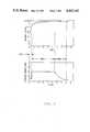
- FIG. 3is a graphical illustration of charging current and battery voltage for three sequential charging modes for a 10-cell, 10-ampere hour Nickel-Cadium battery.
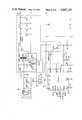
- FIGS. 4, 5 and 6 taken togetheris a schematic diagram of a practical electronic circuit of a battery charger which can be utilized to perform the functions illustrated in FIG. 1.
- This inventionis described in terms of specific electronic components and specific batteries to be charged. However, the invention is applicable to different electronic circuit configurations and different types of temperature sensitive batteries.
- a power connector 10conductively connects an external source of power 18 to the rectifier and filter 12 to supply power to the rectifier and filter 12.
- the power supplied to the rectifier and filter 12 through power connector 10can be either AC or DC e.g. 10-30 VDC or 10-22 VAC for charging a 10 cell Nickel-Cadmium battery.
- the power connector 10may be any connector device selected by the user which is capable of transmitting the current and voltages associated with the battery of the particular application.
- the switching type voltage regulator 14is conductively connected to receive direct current power from rectifier and filter 12.
- the regulator 14is also conductively connected to controller 20 to receive switching signals from controller 20 which cause the regulator 14 to maintain a desired voltage on regulator output line 22 or alternatively to limit the current supplied to battery 16.
- a temperature sensing devicesuch as a thermistor 24 is disposed in the battery 16 to sense the temperature of battery 16.
- temperature stable resistors 26, 28 and 30are connected in series across the battery terminal 32 and 34.
- Thermistor 24is connected in parallel with resistor 28.
- resistors 26, 28 and 30 along with thermistor 24form a modified resistive voltage divider network connected across battery terminals 32 and 34.
- Actual values for the resistors 26, 28 and 30 and thermistor 24 of the modified voltage divider network that will provide an output signal for achieving the voltage/temperature conditions as illustrated in FIG. 2can be determined experimentally. If desired a computer program can be written to aid in determination of these component values. As a further enhancement, a computer program can be written to determine component values for the modified voltage divider network wherein the voltage temperature characteristic of the divider network plots as a segment of a circle and wherein the segment passes through the experimentally determined points that provide safe charging at the existing temperature of the battery.
- An output for the modified voltage divideris taken at node 36 as a voltage signal 38, signal 38 being a temperature compensated voltage signal by virtue of responding to thermistor 24 and the voltage across battery terminal 32 and 34.
- Signal 38is provided as an external voltage input signal to controller 20 for utilization by a voltage adjust circuit in controller 20 as will be explained more fully hereinafter.
- a constant 5 volt reference signal 40is also provided to controller 20 for utilization by the voltage adjust circuit.
- Resistor 42is a current sense resistor, connected between the voltage regulator 14 and ground. Resistor 42 is a low value resistor typically about 0.1 ohm, and receives a current via line 44 proportional to the charging current supplied from the voltage regulator 14 to the battery 16 via regulator output line 22. The voltage developed across resistor 42 is utilized as a external voltage signal 48 representative of the actual charging current supplied to battery 16 and is provided through line 46 and resistor 50 as an input to controller 20. Signal 48 is utilized by a current limit circuit of controller 20 as will be described more fully hereinafter. A ground reference signal 52 is also provided to controller 20 for utilization by the current limit circuit. A switch 54 and resistor 56 are connected in series from line 48 to ground such that operation of switch 54 causes an abrupt change in signal 48.
- the TCVSis also provided to the positive input of a comparator 58 which compares TCVS signal 38 with a 4.5 volt reference signal 60.
- the output of comparator 58is operatively connected to switch 54.
- the output of comparator 58is also utilized for inhibit signal 62 which is provided from comparator 58 as an input to timer 64.
- Timer 64which is a resettable binary counter, is provided with a clock signal 66 from controller 20.
- the clock signal 66is provided from the sync output of controller 20 to the count input of timer 64.
- a timeout period for timer 64is set to a desired time by selecting an appropriate output count for activating the time out signal 68.
- timer 64is reset to 0 via a reset signal 70 which can be a signal from an external source, or a power up reset signal.
- Timer 64counts a specified number of pulses provided from controller 20 and activates the time out signal 68 on reaching the specified count.
- Signal 68is provided from counter 64 to the halt input of controller 20.
- the time out signal 68provides an indication to controller 20 that the voltage of the battery being charged has not reached a value of about 90 percent of TCVS during the timing period, typically 40 minutes, determined by timer 64. In the event time out signal 68 is activated charging of the battery is halted, to prevent possible further damage to a battery having a short circuit between cell plates.
- the controller 20is comprised of several circuits including a voltage adjust circuit, a current limit circuit, an oscillator circuit which produces a logic clock signal for synchronization purposes, a remote shutdown or halt circuit, and an output driver circuit for providing the switching signals to regulator 14.
- the controller 20provides an output in response to appropriate voltage signals fed back to the controller 20 from external sources.
- the voltage adjust circuit of controller 20responds to signals 38 and 40, by modulating the pulse width of the switching signal 72 in such a manner to reduce the difference between signals 38 and 40 to zero.
- the feedback signalis a dc voltage level between 0-5 volts.
- a constant 5-volt potential for signal 40provides for maximum modulation of switching signals 72 in response to signal 38.
- the controller 20will provide switching signals 72 that will cause the voltage at node 36 to equal the reference signal 40.
- the voltage at node 36corresponds to a proportionally higher voltage across battery terminal 32 and 34.
- control of pulse width modulation of switching signal 72is automatically transferred to the current limit circuit of controller 20.
- the controller 20responds to two external voltage signals, one being a limiting valve for the battery charging current as represented by signal 48, and the other signal being a TCVS as represented by signal 38. Controller 20 thus maintains constant either the desired charging current as represented by signal 48 or the desired battery voltage as represented by signal 38.
- a suitable controller which can be utilized in the circuit illustrated in FIG. 1is an SG2526J, Regulating Pulse Width Modulator, commercially available from Unitrode Corporation, Lexington, Mass.
- the switching type voltage regulatorcan be any convential switching regulator which accepts a dc input voltage from a power source and switching signals from a controller, and provides a regulated output voltage despite variation in the input voltage and variations in the load on the regulator.
- switching type regulatorsregulate the output voltage by varying the duty cycle of power transistor switches.
- the switching type voltage regulatorcomprises a pair of N-channel mosfets for switching the primary winding of a split winding step up power transformer.
- D.C. poweris received at the center of the primary winding of the power transformer, and a dc output is delivered from a conventional full wave rectifier and filter connected to the secondary of the power transformer.
- the output of the voltage regulator 14is connected to the battery 16.
- a charging program in which the current or the voltage applied to a fully discharged Nickel-Cadium battery is sequentially varied over timecan be implemented with the charger circuit illustrated in FIG. 1.
- Several charging modesare known including (1) constant current, (2) constant voltage, (3) pulse current, (4) trickle current, and (5) various charge rates such as a 5-hour rate (C5) in which full capacity of the battery is restored in 5 hours.
- a batterybe restored to a fully charged state within a specific time period after full or partial discharge without endangering the battery.
- Rapid recharging or excessive overcharging of the batterycan result in the evolution of substantial amounts of undesirable gases. Further, rapid recharging or excessive overcharging can overheat the battery to the point at which thermal runaway will occur. Generally speaking rapid recharging or excessive overcharging seriously degrades the useful life of the battery.
- a successful charging programmust recognize and be responsive to practical characteristics of the battery to be charged.
- the battery charger of this inventionprovides a charging program that is automatically responsive to the state of discharge of the battery and simultaneously prevents application of a high charge rate to a battery having a shorted cell. Further, an efficient charge rate is provided for the degree of discharge of the battery and the temperature of the battery.
- a constant charging current applied to the battery 16is limited by signal 48 of controller 20 to 0.5 amperes.
- the constant current of 0.5 ampereswhich is a C/20 rate, is maintained until the TCVS 38 attains a value of 4.5 volts.
- the C20 ratewhich can be considered a trickle rate, can be maintained even with some damaged cells for extended periods without further damage to the battery.
- a predetermined period of timeis allowed by timer 64 for the TCVS 38 to attain 4.5 volts as represented by signal 60.
- Signal 60is representative of the minimum voltage that a 10-cell Nickel-Cadmium battery should attain with a C/20 charge rate maintained for 40 minuted. Stated another way, signal 60 is representative of a voltage that a 10-cell Nickel-Cadmium battery could not attain without overcharging if the battery has at least one shorted cell. This mode is provided for the purpose of detecting batteries having shorted cells.
- the first modeis typically initiated by a power up signal applied to timer 64, and is normally terminated by comparator 58 operating switch 54 when the TCVS 38 attains 90 percent of its desired value.
- the length of time that the first mode remains in effectcan range from a few seconds to 40 minutes depending on the condition of the battery being charged.
- a second constant current modeis entered in which a constant current of two amperes is supplied to the battery 16.
- Mode 2is generally the main charging mode for charging the battery 16, since this mode is maintained while the battery state of charge is between about 20 percent and about 95 percent of the battery's fully charged capacity. It is noted that the 2-ampere current supplied to the battery 16 during the constant current charging of mode 2 represents a C/5 charge rate which charge rate would fully charge the battery 16 in 5 hours. Thus, mode 2 is maintained for a length of time dependent on the initial state of discharge of the battery 16.
- Mode 2is terminated when the TCVS 38 attains a value of 5 volts a provided by signal 40.
- Signal 40is representative of the voltage across battery terminals 32-34 that provides the desired voltage illustrated in FIG. 2 across battery terminals 32-34 for the existing temperature of the battery. Thus for any temperature between -20° C. and +50° C., a temperature compensated voltage as illustrated in FIG. 2 can be provided for charging battery 16 in a constant voltage charging mode.
- the third modewhich is a constant voltage mode
- the voltage as depicted in FIG. 2 and as representative of signal 38is applied to battery 16.
- the battery 16is nearly fully charged at the beginning of mode 3 and with the constant voltage applied between the battery terminals 32 and 34, the charge current can vary in accordance with the battery demand.
- a charging program as illustrated in FIG. 3comprises three charging modes, each mode related to the initial state of the battery or the amount of charge to be delivered to the battery.
- Controller 20delivers switching signals to regulator 14 to provide charging current to the battery as limited to a C/20 rate by signal 48.
- the battery voltagerises rapidly in response the the C/20 charge rate to about 1.29 volts/cell or 12.9 volts for the battery terminals in 40 minutes or less, depending on the initial state of the battery.
- mode 2 comparator 58changes state and manipulates signal 48 to require a C/5 charge rate.
- the battery voltagerises slowly from 12.9 to 14.35 volts in about 4-5 hours in response to the C/5 charge rate.
- Mode 2is terminated when the TCVS signal 38 attains a value of 5 volts.
- control of switching signals 72is transferred from the current limit circuit to the voltage adjust circuit of controller 20.
- controller 20provides switching signals to regulator 14 to maintain a constant 14.35 volts across battery terminals 32 and 34.
- the charging current in mode 3which is allowed to vary as the battery 16 demands, decays rather rapidly since the battery is essentially fully charged at the end of mode 2.
- FIGS. 4, 5 and 6taken together illustrate a circuit including specification of the values for capacitors, inductors and resistors, which may be utilized to implement the functions illustrated in FIG. 1.
- the circuitis preferably implemented utilizing a combination of linear integrated circuits and digital integrated circuits along with discrete components such as diodes, MOSFET transistors and a transformer in addition to resistors and capacitors.
- the integrated circuits illustrated in FIGS. 4, 5 and 6may be obtained from a number of suppliers. The function of each of these integrated circuits is fully described by the manufacturer of these integrated circuits and the manner in which the circuit operates would be obvious to one skilled in the art of electronics.
- FIGS. 1-6The invention has been illustrated and described in terms of a preferred embodiment as illustrated in FIGS. 1-6. As has been previously discussed, reasonable variations and modifications are possible by those skilled in the art within the scope of the disclosure and the appended claims.
Landscapes
- Engineering & Computer Science (AREA)
- Power Engineering (AREA)
- Charge And Discharge Circuits For Batteries Or The Like (AREA)
Abstract
Description
This invention relates to battery chargers. In one aspect, it relates to temperature compensating the charging voltage applied to a battery. In another aspect it relates to rapidly charging a temperature sensitive battery without damage to the battery.
In many instances Nickel-Cadmium batteries are utilized for applications where the battery is the only source of energy in the equipment. One such application is a digital radio telemetry system for recording seismic data. In this application remote units are powered by rechargeable Nickel-Cadmium battery packs, which can power a remote unit for about 72 hours of normal use. Typically, the battery packs in the remote units are either removed after a period of use and replaced with fully charged packs, or are recharged while in place in the remote unit from a portable source which can supply either AC or DC power suitable for recharging the Nickel-Cadmium battery packs. In any event maintaining the seismic recording system requires safely recharging the Nickel-Cadmium battery packs from whatever the level of discharge of the battery, including a deep discharge, to a full charge in 8 hours or less.
Rapid charging of Nickel-Cadmium batteries involves problems relating to both thermal conditions and voltage conditions. One noteworthy problem is the gassing of the battery, wherein oxygen produced by the charging reaction builds up pressure that can exceed limits of the case, at which time venting of the battery would occur. This gassing condition is temperature dependent. In a battery which is less than about 60 percent fully charged and at or above room temperature, 25 degrees C., the oxygen produced by the charging reaction chemically recombines thereby preventing the buildup of pressure. Below room temperature the oxygen does not recombine as readily thereby allowing pressure to build up. Consequently, it is desirable to decrease the charge rate as the temperature drops, or as the battery becomes fully charged.
Another temperature dependent condition is the efficiency of the charger. The charging efficiency may be defined as the ratio of the output of a battery to the input required to restore the capacity. As the temperature increases the charging efficiency decreases.
Voltage dependent conditions occur when applying constant current to a Nickel-Cadmium battery. For example, in applying a 5-hour rate constant current to a fully discharged cell, the cell voltage increases slowly to about 1.4 volts in about 4 hours, after which it rapidly increases to about 1.6 volts where it remains until the charge is finished.
Because of the notoriety of these problems, many circuits have been proposed for generating a reference voltage which varies in a manner to produce an effective charge rate for a Nickel-Cadmium battery. Generally, the type of charging system proposed requires that there be some form of transfer from a high charge rate to a low charge rate in response to voltage and/or temperature sensing. In addition, the operation of the charging circuit is typically based on compensating the charging circuit to match the temperature characteristics of an ideal Nickel-Cadmium battery.
The type of battery chargers described above are deficient for charging a battery having a malfunction or cell damage such as a short circuit between cell plates. Damage to the battery may result from the use of these chargers because the critical voltage to be sensed which would transfer the high level operation to a low level operation may be at a higher voltage level than can be achieved with a damaged cell.
It is thus an object of this invention to provide a method and apparatus for charging a temperature sensitive battery at a constant voltage and with current limiting. It is another object of this invention to provide a reference voltage which varies with the temperature of the battery, and is representative of a safe and efficient voltage that a constant voltage type charger could apply to a Nickel-Cadium battery. Still another object of this invention is to provide method and apparatus for detecting cell damage such as a short circuit between plates.
In accordance with the invention, apparatus and method are provided for charging a battery in a rapid manner without damage to the battery. A battery charging circuit comprises a serial arrangement of an unregulated power source, a switching type voltage regulator and a battery to be charged. A controller is provided for the voltage regulator. The controller responds to external voltage signals, and provides signals to the voltage regulator that switch on and off the flow of charging current to the battery. The switching occurs in such a manner that the output voltage of the regulator is maintained at a desired value, or the current delivered to the battery is limited at a desired value.
The external voltage signals provided to the controller are: (1) a signal representative of the actual charging current supplied to the battery, and (2) a temperature compensated voltage signal (TCVS) representative of the voltage that a constant voltage type charger could safely apply to a partially charged (about 50 percent or more) Nickel-Cadmium battery at the existing temperature of the battery.
The TCVS is generated by a modified resistive voltage divider network connected across the battery terminals comprising a combination of temperature stable resistors and a thermistor. The thermistor is positioned in the case of the battery to respond to battery temperature, and is connected in parallel with one of the temperature stable resistors of the voltage divider network. It has been found that by modifying a resistive voltage divider to include the thermistor in parallel with one of the resistors, it is possible, with proper selection of component values for the resistors and thermistor, to cause an output of the voltage divider network to correspond to voltage/temperature charging characteristics that are known to provide efficient charging conditions for the battery. Thus a safe, efficient constant charging voltage for a partially discharged temperature sensitive battery such as a Nickel-Cadium battery can be experimentally determined at a plurality of temperatures and a graph of voltage vs temperature for the battery can be produced. With proper selection of ohmic values for the resistors and thermistor, the output of the modified voltage divider can be made to closely represent the experimentally determined voltage that provides safe, efficient charging of the battery at the existing temperature of the battery.
The above described signals are utilized to control a charging program for the battery in which the current and voltage of a charger are sequentially varied over time in order to rapidly and safely place the battery in a state of full charge.
Other objects and advantages of the invention will be apparent from the foregoing brief description of the invention and the claims as well as the detailed description of this invention and the drawings in which:
FIG. 1 is a simplified diagrammatic illustration of a battery charger of this invention.
FIG. 2 is a graphical illustration of a safe, efficient voltage as a function of temperature that could be applied to a 10-cell Nickel-Cadmium battery.
FIG. 3 is a graphical illustration of charging current and battery voltage for three sequential charging modes for a 10-cell, 10-ampere hour Nickel-Cadium battery.
FIGS. 4, 5 and 6 taken together is a schematic diagram of a practical electronic circuit of a battery charger which can be utilized to perform the functions illustrated in FIG. 1.
This invention is described in terms of specific electronic components and specific batteries to be charged. However, the invention is applicable to different electronic circuit configurations and different types of temperature sensitive batteries.
Referring now to the drawings and in particular to FIG. 1, there is illustrated a rectifier andfilter 12, a switchingtype voltage regulator 14, and abattery 16 connected in series to form a path for the charging current for thebattery 16. Apower connector 10 conductively connects an external source ofpower 18 to the rectifier and filter 12 to supply power to the rectifier and filter 12. The power supplied to the rectifier and filter 12 throughpower connector 10 can be either AC or DC e.g. 10-30 VDC or 10-22 VAC for charging a 10 cell Nickel-Cadmium battery. Thepower connector 10 may be any connector device selected by the user which is capable of transmitting the current and voltages associated with the battery of the particular application.
The switchingtype voltage regulator 14 is conductively connected to receive direct current power from rectifier andfilter 12. Theregulator 14 is also conductively connected tocontroller 20 to receive switching signals fromcontroller 20 which cause theregulator 14 to maintain a desired voltage onregulator output line 22 or alternatively to limit the current supplied tobattery 16.
A temperature sensing device such as athermistor 24 is disposed in thebattery 16 to sense the temperature ofbattery 16. Preferably temperaturestable resistors battery terminal resistor 28. Thus the combination ofresistors thermistor 24 form a modified resistive voltage divider network connected acrossbattery terminals
Actual values for theresistors thermistor 24 of the modified voltage divider network that will provide an output signal for achieving the voltage/temperature conditions as illustrated in FIG. 2 can be determined experimentally. If desired a computer program can be written to aid in determination of these component values. As a further enhancement, a computer program can be written to determine component values for the modified voltage divider network wherein the voltage temperature characteristic of the divider network plots as a segment of a circle and wherein the segment passes through the experimentally determined points that provide safe charging at the existing temperature of the battery.
An output for the modified voltage divider is taken atnode 36 as avoltage signal 38,signal 38 being a temperature compensated voltage signal by virtue of responding tothermistor 24 and the voltage acrossbattery terminal Signal 38 is provided as an external voltage input signal to controller 20 for utilization by a voltage adjust circuit incontroller 20 as will be explained more fully hereinafter. A constant 5volt reference signal 40 is also provided to controller 20 for utilization by the voltage adjust circuit.
As indicated in FIG. 1, thecontroller 20 is comprised of several circuits including a voltage adjust circuit, a current limit circuit, an oscillator circuit which produces a logic clock signal for synchronization purposes, a remote shutdown or halt circuit, and an output driver circuit for providing the switching signals toregulator 14. As previously mentioned, thecontroller 20 provides an output in response to appropriate voltage signals fed back to thecontroller 20 from external sources. The voltage adjust circuit ofcontroller 20 responds tosignals signal 72 in such a manner to reduce the difference betweensignals signal 40 provides for maximum modulation of switchingsignals 72 in response to signal 38.
Thecontroller 20 will provide switchingsignals 72 that will cause the voltage atnode 36 to equal thereference signal 40. The voltage atnode 36 corresponds to a proportionally higher voltage acrossbattery terminal node 36 cause the charging current to exceed the limiting value determined bysignal 48, control of pulse width modulation of switchingsignal 72 is automatically transferred to the current limit circuit ofcontroller 20. Essentially, thecontroller 20 responds to two external voltage signals, one being a limiting valve for the battery charging current as represented bysignal 48, and the other signal being a TCVS as represented bysignal 38.Controller 20 thus maintains constant either the desired charging current as represented bysignal 48 or the desired battery voltage as represented bysignal 38.
A suitable controller which can be utilized in the circuit illustrated in FIG. 1 is an SG2526J, Regulating Pulse Width Modulator, commercially available from Unitrode Corporation, Lexington, Mass.
The switching type voltage regulator can be any convential switching regulator which accepts a dc input voltage from a power source and switching signals from a controller, and provides a regulated output voltage despite variation in the input voltage and variations in the load on the regulator. Generally, switching type regulators regulate the output voltage by varying the duty cycle of power transistor switches.
In a specific and presently preferred embodiment of this invention as illustrated in FIG. 4, the switching type voltage regulator comprises a pair of N-channel mosfets for switching the primary winding of a split winding step up power transformer. D.C. power is received at the center of the primary winding of the power transformer, and a dc output is delivered from a conventional full wave rectifier and filter connected to the secondary of the power transformer. As illustrated in FIG. 6, the output of thevoltage regulator 14 is connected to thebattery 16.
A charging program in which the current or the voltage applied to a fully discharged Nickel-Cadium battery is sequentially varied over time can be implemented with the charger circuit illustrated in FIG. 1. Several charging modes are known including (1) constant current, (2) constant voltage, (3) pulse current, (4) trickle current, and (5) various charge rates such as a 5-hour rate (C5) in which full capacity of the battery is restored in 5 hours.
As has been previously stated, in some applications, it is desirable that a battery be restored to a fully charged state within a specific time period after full or partial discharge without endangering the battery. Rapid recharging or excessive overcharging of the battery can result in the evolution of substantial amounts of undesirable gases. Further, rapid recharging or excessive overcharging can overheat the battery to the point at which thermal runaway will occur. Generally speaking rapid recharging or excessive overcharging seriously degrades the useful life of the battery.
A successful charging program must recognize and be responsive to practical characteristics of the battery to be charged. The battery charger of this invention provides a charging program that is automatically responsive to the state of discharge of the battery and simultaneously prevents application of a high charge rate to a battery having a shorted cell. Further, an efficient charge rate is provided for the degree of discharge of the battery and the temperature of the battery.
In the first mode as illustrated in FIG. 3, a constant charging current applied to thebattery 16 is limited bysignal 48 ofcontroller 20 to 0.5 amperes. The constant current of 0.5 amperes, which is a C/20 rate, is maintained until theTCVS 38 attains a value of 4.5 volts. The C20 rate, which can be considered a trickle rate, can be maintained even with some damaged cells for extended periods without further damage to the battery. A predetermined period of time is allowed bytimer 64 for theTCVS 38 to attain 4.5 volts as represented bysignal 60.
The first mode is typically initiated by a power up signal applied totimer 64, and is normally terminated bycomparator 58operating switch 54 when theTCVS 38 attains 90 percent of its desired value. Thus, the length of time that the first mode remains in effect can range from a few seconds to 40 minutes depending on the condition of the battery being charged.
In the second mode as illustrated in FIG. 3, a second constant current mode is entered in which a constant current of two amperes is supplied to thebattery 16.Mode 2 is generally the main charging mode for charging thebattery 16, since this mode is maintained while the battery state of charge is between about 20 percent and about 95 percent of the battery's fully charged capacity. It is noted that the 2-ampere current supplied to thebattery 16 during the constant current charging ofmode 2 represents a C/5 charge rate which charge rate would fully charge thebattery 16 in 5 hours. Thus,mode 2 is maintained for a length of time dependent on the initial state of discharge of thebattery 16.
In the third mode, which is a constant voltage mode, the voltage as depicted in FIG. 2 and as representative ofsignal 38 is applied tobattery 16. Thebattery 16 is nearly fully charged at the beginning ofmode 3 and with the constant voltage applied between thebattery terminals
As an example for charging a 10-cell, 10 AH Nickel-Cadium battery at room temperature, a charging program as illustrated in FIG. 3 comprises three charging modes, each mode related to the initial state of the battery or the amount of charge to be delivered to the battery.
Inmode 1 the battery voltage rises rapidly from some state of discharge, which may be effectively dead and may have cell damage. In the 10-cell Nickel-Cadium battery under discussion an average cell voltage would be less than 1.0 volt d.c. for a battery terminal voltage of for example 9 volts.
When theTCVS 38 is 4.5 volts at 25° C. a corresponding battery voltage is 12.9 volts which is 90 percent of the 14.35 volts indicated on FIG. 2 for safe efficient charging at 25° C. On attaining a value of 4.5 volts forTCVS signal 38,mode 1 is terminated.
Inmode 2comparator 58 changes state and manipulatessignal 48 to require a C/5 charge rate. Duringmode 2 the battery voltage rises slowly from 12.9 to 14.35 volts in about 4-5 hours in response to the C/5 charge rate.Mode 2 is terminated when theTCVS signal 38 attains a value of 5 volts. Inmode 3 control of switchingsignals 72 is transferred from the current limit circuit to the voltage adjust circuit ofcontroller 20. At 25°C. controller 20 provides switching signals toregulator 14 to maintain a constant 14.35 volts acrossbattery terminals mode 3 which is allowed to vary as thebattery 16 demands, decays rather rapidly since the battery is essentially fully charged at the end ofmode 2.
FIGS. 4, 5 and 6 taken together illustrate a circuit including specification of the values for capacitors, inductors and resistors, which may be utilized to implement the functions illustrated in FIG. 1. The circuit is preferably implemented utilizing a combination of linear integrated circuits and digital integrated circuits along with discrete components such as diodes, MOSFET transistors and a transformer in addition to resistors and capacitors. The integrated circuits illustrated in FIGS. 4, 5 and 6 may be obtained from a number of suppliers. The function of each of these integrated circuits is fully described by the manufacturer of these integrated circuits and the manner in which the circuit operates would be obvious to one skilled in the art of electronics.
Power supplies and other conventional circuitry required by the various integrated circuits have not been fully illustrated in FIGS. 4, 5 and 6 for the sake of simplicity. Again, such power supplies and additional circuitry are specified by the manufacturers and are well known to those skilled in the art of electronics.
The invention has been illustrated and described in terms of a preferred embodiment as illustrated in FIGS. 1-6. As has been previously discussed, reasonable variations and modifications are possible by those skilled in the art within the scope of the disclosure and the appended claims.
Claims (7)
1. Apparatus for charging a battery comprising:
a switching type voltage regulator having a current sense output wherein said regulator is connected in a series circuit between a power source and a first terminal of said battery, said regulator receiving unregulated dc power from said power source and delivering regulated power to said first terminal of said battery;
a controller for said regulator operatively connected to provide switching signals to said regulator, said controller having a voltage adjust circuit and a current limit circuit, and having a first external voltage input and a first reference voltage input associated with said current limit circuit, and having a second external voltage input and a second reference voltage input associated with said voltage adjust circuit, said voltage adjust circuit and said current limit circuit being operatively connected to modulate said switching signals in response to the potential applied to said first and second external voltage inputs;
a current sense resistor having a first terminal connected to said current sense output of said regulator and a second terminal connected to a second terminal of said battery;
means for connecting a current sense output voltage from said regulator to said first external voltage input of said controller for modulating said switching signals in response to said current sense output voltage;
a resistive voltage divider network connected across said first and second terminals of said battery;
a thermistor disposed to measure the temperature of said battery, wherein said thermistor is connected in parallel with a resistor of said resistive voltage divider network;
means for operatively connecting a node of said resistive voltage divider network to said second external voltage input of said controller for modulating said switching signals in response to said thermistor and the voltage of said battery;
means for connecting a ground potential to said first reference voltage input; and
means for connecting a reference potential to said second reference voltage input wherein said reference potential corresponds to the maximum modulation of said switching signals that can be provided by said controller.
2. Apparatus in accordance with claim 1 additionally comprising:
a timer for generating a time out signal, said timer having a counting circuit for counting synchronization pulses received from said controller and having an inhibit circuit with an associated input, and having an output associated with said time out signal;
a comparator having two inputs and an output, a first input of which is connected to said node of said voltage divider network and a second input of which is connected to a fixed reference voltage;
means for connecting said comparator output to said input associated with said inhibit circuit of said timer;
a halt circuit associated with said controller;
means for connecting said output of said timer to said halt circuit of said controller wherein charging of said battery is halted if said time out signal is present.
3. Apparatus in accordance with claim 2 wherein said means for connecting a current sense output voltage from said regulator to said first external voltage input of said controller comprises:
a first resistor connected between said first terminal of said current sense resistor and said first external voltage input of said controller;
a second resistor connected between said first external voltage input of said controller and said second terminal of said current sense resistor.
switch means having a circuit path for connect/disconnect switching of said second resistor and said first external voltage input of said controller; and
means for connecting said output of said comparator to said switch means, wherein said second resistor is disconnected when the voltage at said first input of said comparator is less than the voltage at said second input of said comparator.
4. Apparatus in accordance with claim 3, additionally comprising:
power rectifier and filter means serially connected between said power source and said switching regulator for rectifying ac power received from said power source and for passing unregulated dc power received from said power source to said regulator, and
power connector means for removable connection between said power source and said power rectifier and filter.
5. A method of charging a temperature sensitive battery without damage to the battery comprising the following sequential steps:
(a) generating a temperature compensated voltage signal representative of a voltage for safely charging said battery at the exisitng temperature of said battery;
(b) supplying a constant current having a first magnitude to said battery until said temperature compensated voltage signal attains a first predetermined voltage level representative of the minimum voltage that said battery should attain within a predefined time period in response to said constant current having said first magnitude if said battery is undamaged;
(c) supplying a constant current having a second magnitude which is greater than said first magnitude to said battery, said second magnitude of constant current being applied to the battery until said temperature compensated voltage signal attains a second predetermined level representative of a predetermined voltage which can be applied across the terminals of said battery for safely and efficiently charging said battery at the existing temperature of said battery; said second predetermined voltage level being higher than said first predetermined voltage level; and
(d) impressing a constant voltage across the terminals of said battery, said constant voltage corresponding to the voltage attained by said temperature compensated voltage signal in step.
6. A method in accordance with claim 5 wherein said step of generating a temperature compensated voltage signal comprises the steps of:
modifying a resistive voltage divider network comprising three resistors in series, by connecting a thermistor in parallel with the central one of the resistors of said resistive voltage divider network to provide a modified voltage divider network;
selecting ohmic values for the resistors and thermistor of said modified resistive voltage divider network that will provide an output from the modified voltage divider network that varies with temperature and voltage of the battery in a manner that corresponds to a predetermined voltage vs. temperature charging characteristics of the battery; and
connecting the resistive elements of said modified voltage divides network across the terminals of the battery and disposing the thermistor in the case of the battery, such that said temperature compensated voltage signal is generated at said output of said modified voltage divider network.
7. A method in accordance with claim 6 additionally comprising the steps of:
initializing a time period on starting supply of said constant current having a first magnitude to said battery in step, said time period being sufficiently long to allow said temperature compensated voltage signal for an undamaged but fully discharged battery to attain the first predetermined level required in step; and
activating a time out signal at the end of said time period wherein said time out signal stops flow of charging current to said battery;
inhibiting said time out signal if said temperature compensated voltage signal attains said first predetermined level in step.
Priority Applications (1)
| Application Number | Priority Date | Filing Date | Title |
|---|---|---|---|
| US06/812,204US4667143A (en) | 1985-12-23 | 1985-12-23 | Battery charger having temperature compensated charge rate |
Applications Claiming Priority (1)
| Application Number | Priority Date | Filing Date | Title |
|---|---|---|---|
| US06/812,204US4667143A (en) | 1985-12-23 | 1985-12-23 | Battery charger having temperature compensated charge rate |
Publications (1)
| Publication Number | Publication Date |
|---|---|
| US4667143Atrue US4667143A (en) | 1987-05-19 |
Family
ID=25208852
Family Applications (1)
| Application Number | Title | Priority Date | Filing Date |
|---|---|---|---|
| US06/812,204Expired - Fee RelatedUS4667143A (en) | 1985-12-23 | 1985-12-23 | Battery charger having temperature compensated charge rate |
Country Status (1)
| Country | Link |
|---|---|
| US (1) | US4667143A (en) |
Cited By (169)
| Publication number | Priority date | Publication date | Assignee | Title |
|---|---|---|---|---|
| US4871958A (en)* | 1986-12-26 | 1989-10-03 | Toko, Inc. | Charging circuit |
| US5079716A (en)* | 1990-05-01 | 1992-01-07 | Globe-Union, Inc. | Method and apparatus for estimating a battery temperature |
| US5089765A (en)* | 1989-08-11 | 1992-02-18 | Ryobi Limited | Battery charger and charging method |
| US5095260A (en)* | 1990-12-24 | 1992-03-10 | Century Manufacturing Company | Self limiting battery charger |
| US5113128A (en)* | 1989-10-18 | 1992-05-12 | Ryobi Limited | Battery charger and charging method |
| EP0498715A1 (en)* | 1991-02-08 | 1992-08-12 | Saft | Process for optimizing the charge of an accumulator battery and apparatus for carrying out the process |
| WO1992016991A1 (en)* | 1991-03-13 | 1992-10-01 | Norvik Technologies Inc. | Charging circuits for rechargeable batteries and cells |
| US5180962A (en)* | 1990-07-16 | 1993-01-19 | Reliance Comm/Tec Corporation | Apparatus for temperature compensating one or more battery chargers |
| US5187425A (en)* | 1990-11-09 | 1993-02-16 | Ast Research, Inc. | Rechargeable battery controller |
| US5197334A (en)* | 1991-06-04 | 1993-03-30 | Schlumberger Industries, Inc. | Programmable compensation of bridge circuit thermal response |
| EP0532232A3 (en)* | 1991-09-13 | 1994-02-02 | American Telephone & Telegraph | |
| US5291118A (en)* | 1991-06-14 | 1994-03-01 | Furukawa Denchi Kabushiki Kaisha | Device for detecting connection or disconnection of a battery to an electric charger |
| US5339018A (en)* | 1989-06-30 | 1994-08-16 | Analog Devices, Inc. | Integrated circuit monitor for storage battery voltage and temperature |
| US5347224A (en)* | 1992-02-26 | 1994-09-13 | Analog Devices, Inc. | Current monitoring circuit having controlled sensitivity to temperature and supply voltage |
| US5351283A (en)* | 1991-12-09 | 1994-09-27 | Matsushita Electric Industrial Co., Ltd. | Vehicle-mounted charging apparatus for portable telephone sets |
| US5352968A (en)* | 1992-05-28 | 1994-10-04 | Apple Computer, Inc. | Battery charge state determination |
| US5371453A (en)* | 1993-01-28 | 1994-12-06 | Motorola, Inc. | Battery charger system with common charge and data exchange port |
| US5451857A (en)* | 1992-09-15 | 1995-09-19 | Safetran Systems Corporation | Temperature compensated, regulated power supply and battery charger for railroad signal use |
| GB2290426A (en)* | 1994-06-16 | 1995-12-20 | Hyundai Motor Co Ltd | Charging batteries of electric vehicles |
| US5504416A (en)* | 1993-12-15 | 1996-04-02 | Unitrode Corporation | Battery charger circuit including battery temperature control |
| EP0729212A1 (en)* | 1995-02-27 | 1996-08-28 | Alcatel | Method for charging a lithium battery provided with a carbon anode |
| US5619118A (en)* | 1991-02-14 | 1997-04-08 | Chartec Laboratories A/S | Method and an apparatus for charging a rechargeable battery |
| US5633576A (en)* | 1993-01-19 | 1997-05-27 | Premier Engineered Products, Inc. | Battery charging method with stepped current profile with operating parameter compensation and associated charger |
| US5659240A (en)* | 1995-02-16 | 1997-08-19 | General Electric Company | Intelligent battery charger for electric drive system batteries |
| US5686815A (en)* | 1991-02-14 | 1997-11-11 | Chartec Laboratories A/S | Method and apparatus for controlling the charging of a rechargeable battery to ensure that full charge is achieved without damaging the battery |
| US5703468A (en)* | 1995-03-17 | 1997-12-30 | Petrillo; Gino A. | Electrical charge control apparatus and method for photovoltaic energy conversion systems |
| EP0655172B1 (en)* | 1992-08-14 | 1998-01-07 | Chartec Laboratories A/S | Method for battery charging and a battery system |
| US5708348A (en)* | 1995-11-20 | 1998-01-13 | Warren Johnson | Method and apparatus for monitoring battery voltage |
| US5856737A (en)* | 1982-06-07 | 1999-01-05 | Norand Corporation | Fast battery charging system and method |
| US5969506A (en)* | 1997-08-11 | 1999-10-19 | C & K Systems, Inc. | Apparatus and method for rapid bulk charging of a lead acid battery |
| US5994875A (en)* | 1996-06-24 | 1999-11-30 | Samsung Electronics Co., Ltd. | Battery charging apparatus and method with charging mode convertible function |
| US5998966A (en)* | 1997-03-14 | 1999-12-07 | International Components Corp. | Microcontrolled battery charger |
| US6037747A (en)* | 1997-10-15 | 2000-03-14 | Lucent Technologies Inc. | Mode selection circuit for a battery and method of operation thereof |
| US6252380B1 (en) | 1984-05-21 | 2001-06-26 | Intermec Ip Corp. | Battery pack having memory |
| US6271643B1 (en) | 1986-12-18 | 2001-08-07 | Intermec Ip Corp. | Battery pack having memory |
| US6307349B1 (en) | 2000-02-24 | 2001-10-23 | Intermec Ip Corp. | Battery pack having memory |
| US6326767B1 (en) | 1999-03-30 | 2001-12-04 | Shoot The Moon Products Ii, Llc | Rechargeable battery pack charging system with redundant safety systems |
| US6424158B2 (en) | 1998-07-27 | 2002-07-23 | Midtronics, Inc. | Apparatus and method for carrying out diagnostic tests on batteries and for rapidly charging batteries |
| US6441585B1 (en) | 1999-06-16 | 2002-08-27 | Midtronics, Inc. | Apparatus and method for testing rechargeable energy storage batteries |
| US6445158B1 (en) | 1996-07-29 | 2002-09-03 | Midtronics, Inc. | Vehicle electrical system tester with encoded output |
| US6456045B1 (en) | 1999-04-16 | 2002-09-24 | Midtronics, Inc. | Integrated conductance and load test based electronic battery tester |
| US6466026B1 (en) | 2001-10-12 | 2002-10-15 | Keith S. Champlin | Programmable current exciter for measuring AC immittance of cells and batteries |
| US6466025B1 (en) | 2000-01-13 | 2002-10-15 | Midtronics, Inc. | Alternator tester |
| US6469511B1 (en) | 2001-07-18 | 2002-10-22 | Midtronics, Inc. | Battery clamp with embedded environment sensor |
| US20020171428A1 (en)* | 1997-11-03 | 2002-11-21 | Bertness Kevin I. | Electronic battery tester with network communication |
| US6495990B2 (en) | 1999-09-01 | 2002-12-17 | Keith S. Champlin | Method and apparatus for evaluating stored charge in an electrochemical cell or battery |
| US20020193955A1 (en)* | 1999-04-08 | 2002-12-19 | Bertness Kevin I. | Battery test module |
| US6544078B2 (en) | 2001-07-18 | 2003-04-08 | Midtronics, Inc. | Battery clamp with integrated current sensor |
| US6556019B2 (en) | 1999-04-30 | 2003-04-29 | Midtronics, Inc. | Electronic battery tester |
| US20030088375A1 (en)* | 2001-10-17 | 2003-05-08 | Bertness Kevin I. | Electronic battery tester with relative test output |
| US6566883B1 (en) | 1999-11-01 | 2003-05-20 | Midtronics, Inc. | Electronic battery tester |
| US20030124417A1 (en)* | 1999-04-08 | 2003-07-03 | Bertness Kevin I. | Battery test module |
| US20030173971A1 (en)* | 2002-03-14 | 2003-09-18 | Bertness Kevin I. | Electronic battery tester with battery failure temperature determination |
| US20030184258A1 (en)* | 2001-06-22 | 2003-10-02 | Vonderhaar J. David | Booster pack with storage capacitor |
| US6633165B2 (en) | 1997-11-03 | 2003-10-14 | Midtronics, Inc. | In-vehicle battery monitor |
| US6696819B2 (en) | 2002-01-08 | 2004-02-24 | Midtronics, Inc. | Battery charge control device |
| US20040036443A1 (en)* | 2000-03-27 | 2004-02-26 | Bertness Kevin I. | Modular battery tester for scan tool |
| US20040046566A1 (en)* | 2002-09-05 | 2004-03-11 | Klang James K. | Electronic battery tester configured to predict a load test result |
| US6707303B2 (en) | 1999-04-08 | 2004-03-16 | Midtronics, Inc. | Electronic battery tester |
| US6737831B2 (en) | 1999-09-01 | 2004-05-18 | Keith S. Champlin | Method and apparatus using a circuit model to evaluate cell/battery parameters |
| FR2849298A1 (en)* | 2002-12-20 | 2004-06-25 | Cit Alcatel | DEVICE FOR MONITORING THE CHARGE STATE, AT CONSTANT VOLTAGE, OF A BATTERY ASSEMBLY WITH SECONDARY ELECTROCHEMICAL GENERATORS |
| US6759849B2 (en) | 2000-03-27 | 2004-07-06 | Kevin I. Bertness | Battery tester configured to receive a removable digital module |
| US20040135552A1 (en)* | 2001-11-12 | 2004-07-15 | Dale Wolin | Battery charging and discharging system optimized for high temperature environments |
| US20040140904A1 (en)* | 2003-01-22 | 2004-07-22 | Bertness Kevin I. | Apparatus and method for protecting a battery from overdischarge |
| US20040157113A1 (en)* | 2002-12-31 | 2004-08-12 | Midtronics, Inc. | Apparatus and method for predicting the remaining discharge time of a battery |
| US6781382B2 (en) | 2002-12-05 | 2004-08-24 | Midtronics, Inc. | Electronic battery tester |
| US6788025B2 (en) | 2001-06-22 | 2004-09-07 | Midtronics, Inc. | Battery charger with booster pack |
| US6795782B2 (en) | 1999-04-08 | 2004-09-21 | Midtronics, Inc. | Battery test module |
| US20040189308A1 (en)* | 2003-03-25 | 2004-09-30 | Bertness Kevin I. | Electronic battery tester |
| US6850037B2 (en) | 1997-11-03 | 2005-02-01 | Midtronics, Inc. | In-vehicle battery monitor |
| US20050073314A1 (en)* | 2003-10-03 | 2005-04-07 | Midtronics, Inc. | Electronic battery tester/charger with integrated battery cell temperature measurement device |
| US6885195B2 (en) | 1996-07-29 | 2005-04-26 | Midtronics, Inc. | Method and apparatus for auditing a battery test |
| US20050099185A1 (en)* | 2003-11-11 | 2005-05-12 | Klang James K. | Apparatus and method for simulating a battery tester with a fixed resistance load |
| US6906523B2 (en) | 2000-09-14 | 2005-06-14 | Midtronics, Inc. | Method and apparatus for testing cells and batteries embedded in series/parallel systems |
| US6906522B2 (en) | 2002-03-29 | 2005-06-14 | Midtronics, Inc. | Battery tester with battery replacement output |
| US6909287B2 (en) | 1997-11-03 | 2005-06-21 | Midtronics, Inc. | Energy management system for automotive vehicle |
| US6913483B2 (en) | 2003-06-23 | 2005-07-05 | Midtronics, Inc. | Cable for electronic battery tester |
| US6914413B2 (en) | 1996-07-29 | 2005-07-05 | Midtronics, Inc. | Alternator tester with encoded output |
| US6941234B2 (en) | 2001-10-17 | 2005-09-06 | Midtronics, Inc. | Query based electronic battery tester |
| US20060006843A1 (en)* | 2004-07-09 | 2006-01-12 | Zengjing Wu | System and method for monitoring a charging period in a battery charger |
| US7003410B2 (en) | 1996-07-29 | 2006-02-21 | Midtronics, Inc. | Electronic battery tester with relative test output |
| US7012433B2 (en) | 2002-09-18 | 2006-03-14 | Midtronics, Inc. | Battery tester upgrade using software key |
| US7081755B2 (en) | 2002-09-05 | 2006-07-25 | Midtronics, Inc. | Battery tester capable of predicting a discharge voltage/discharge current of a battery |
| US7106070B2 (en) | 2004-07-22 | 2006-09-12 | Midtronics, Inc. | Broad-band low-inductance cables for making Kelvin connections to electrochemical cells and batteries |
| US7119686B2 (en) | 2004-04-13 | 2006-10-10 | Midtronics, Inc. | Theft prevention device for automotive vehicle service centers |
| US7126341B2 (en) | 1997-11-03 | 2006-10-24 | Midtronics, Inc. | Automotive vehicle electrical system diagnostic device |
| US7154276B2 (en) | 2003-09-05 | 2006-12-26 | Midtronics, Inc. | Method and apparatus for measuring a parameter of a vehicle electrical system |
| US7198510B2 (en) | 2001-11-14 | 2007-04-03 | Midtronics, Inc. | Kelvin connector for a battery post |
| US7246015B2 (en) | 1996-07-29 | 2007-07-17 | Midtronics, Inc. | Alternator tester |
| US7319304B2 (en) | 2003-07-25 | 2008-01-15 | Midtronics, Inc. | Shunt connection to a PCB of an energy management system employed in an automotive vehicle |
| US20080106234A1 (en)* | 2006-11-06 | 2008-05-08 | Changyong Yun | Hybrid battery and charging method thereof |
| US7398176B2 (en) | 2000-03-27 | 2008-07-08 | Midtronics, Inc. | Battery testers with secondary functionality |
| US7408358B2 (en) | 2003-06-16 | 2008-08-05 | Midtronics, Inc. | Electronic battery tester having a user interface to configure a printer |
| US20080198898A1 (en)* | 2007-02-21 | 2008-08-21 | Taylor John P | Apparatus, system and method for high resolution identification with temperature dependent resistive device |
| US20080258688A1 (en)* | 2007-04-19 | 2008-10-23 | Summit Microelectronics, Inc. | Battery Charging Systems and Methods with Adjustable Current Limit |
| US7446536B2 (en) | 2000-03-27 | 2008-11-04 | Midtronics, Inc. | Scan tool for electronic battery tester |
| US20080278111A1 (en)* | 2007-05-11 | 2008-11-13 | Commissariat A L'energie Atomique | Method for charging a battery of an autonomous system |
| US7479763B2 (en) | 2001-06-22 | 2009-01-20 | Midtronics, Inc. | Apparatus and method for counteracting self discharge in a storage battery |
| US7498767B2 (en) | 2005-02-16 | 2009-03-03 | Midtronics, Inc. | Centralized data storage of condition of a storage battery at its point of sale |
| US7501795B2 (en) | 2001-06-22 | 2009-03-10 | Midtronics Inc. | Battery charger with booster pack |
| US7505856B2 (en) | 1999-04-08 | 2009-03-17 | Midtronics, Inc. | Battery test module |
| US7545146B2 (en) | 2004-12-09 | 2009-06-09 | Midtronics, Inc. | Apparatus and method for predicting battery capacity and fitness for service from a battery dynamic parameter and a recovery voltage differential |
| US7595643B2 (en) | 2003-11-11 | 2009-09-29 | Midtronics, Inc. | Apparatus and method for simulating a battery tester with a fixed resistance load |
| US7598699B2 (en) | 2004-02-20 | 2009-10-06 | Midtronics, Inc. | Replaceable clamp for electronic battery tester |
| US7598744B2 (en) | 2000-03-27 | 2009-10-06 | Midtronics, Inc. | Scan tool for electronic battery tester |
| US7598743B2 (en) | 2000-03-27 | 2009-10-06 | Midtronics, Inc. | Battery maintenance device having databus connection |
| US7642786B2 (en) | 2004-06-01 | 2010-01-05 | Midtronics, Inc. | Battery tester capable of identifying faulty battery post adapters |
| US20100007213A1 (en)* | 2006-09-08 | 2010-01-14 | Panasonic Corporation | Accumulator |
| US7688074B2 (en) | 1997-11-03 | 2010-03-30 | Midtronics, Inc. | Energy management system for automotive vehicle |
| US7705602B2 (en) | 1997-11-03 | 2010-04-27 | Midtronics, Inc. | Automotive vehicle electrical system diagnostic device |
| US7706991B2 (en) | 1996-07-29 | 2010-04-27 | Midtronics, Inc. | Alternator tester |
| US7710119B2 (en) | 2004-12-09 | 2010-05-04 | Midtronics, Inc. | Battery tester that calculates its own reference values |
| US7774151B2 (en) | 1997-11-03 | 2010-08-10 | Midtronics, Inc. | Wireless battery monitor |
| US7772850B2 (en) | 2004-07-12 | 2010-08-10 | Midtronics, Inc. | Wireless battery tester with information encryption means |
| US7777612B2 (en) | 2004-04-13 | 2010-08-17 | Midtronics, Inc. | Theft prevention device for automotive vehicle service centers |
| US7791348B2 (en) | 2007-02-27 | 2010-09-07 | Midtronics, Inc. | Battery tester with promotion feature to promote use of the battery tester by providing the user with codes having redeemable value |
| US7808375B2 (en) | 2007-04-16 | 2010-10-05 | Midtronics, Inc. | Battery run down indicator |
| US7977914B2 (en) | 2003-10-08 | 2011-07-12 | Midtronics, Inc. | Battery maintenance tool with probe light |
| US8164343B2 (en) | 2003-09-05 | 2012-04-24 | Midtronics, Inc. | Method and apparatus for measuring a parameter of a vehicle electrical system |
| US8198900B2 (en) | 1996-07-29 | 2012-06-12 | Midtronics, Inc. | Automotive battery charging system tester |
| US8203345B2 (en) | 2007-12-06 | 2012-06-19 | Midtronics, Inc. | Storage battery and battery tester |
| US8306690B2 (en) | 2007-07-17 | 2012-11-06 | Midtronics, Inc. | Battery tester for electric vehicle |
| US8344685B2 (en) | 2004-08-20 | 2013-01-01 | Midtronics, Inc. | System for automatically gathering battery information |
| US8436619B2 (en) | 2004-08-20 | 2013-05-07 | Midtronics, Inc. | Integrated tag reader and environment sensor |
| US8442877B2 (en) | 2004-08-20 | 2013-05-14 | Midtronics, Inc. | Simplification of inventory management |
| US8513949B2 (en) | 2000-03-27 | 2013-08-20 | Midtronics, Inc. | Electronic battery tester or charger with databus connection |
| US8738309B2 (en) | 2010-09-30 | 2014-05-27 | Midtronics, Inc. | Battery pack maintenance for electric vehicles |
| US8872517B2 (en) | 1996-07-29 | 2014-10-28 | Midtronics, Inc. | Electronic battery tester with battery age input |
| US8958998B2 (en) | 1997-11-03 | 2015-02-17 | Midtronics, Inc. | Electronic battery tester with network communication |
| US9018958B2 (en) | 2003-09-05 | 2015-04-28 | Midtronics, Inc. | Method and apparatus for measuring a parameter of a vehicle electrical system |
| US9201120B2 (en) | 2010-08-12 | 2015-12-01 | Midtronics, Inc. | Electronic battery tester for testing storage battery |
| US9229062B2 (en) | 2010-05-27 | 2016-01-05 | Midtronics, Inc. | Electronic storage battery diagnostic system |
| US9244100B2 (en) | 2013-03-15 | 2016-01-26 | Midtronics, Inc. | Current clamp with jaw closure detection |
| US9255955B2 (en) | 2003-09-05 | 2016-02-09 | Midtronics, Inc. | Method and apparatus for measuring a parameter of a vehicle electrical system |
| US9274157B2 (en) | 2007-07-17 | 2016-03-01 | Midtronics, Inc. | Battery tester for electric vehicle |
| US9312575B2 (en) | 2013-05-16 | 2016-04-12 | Midtronics, Inc. | Battery testing system and method |
| EP3007307A1 (en)* | 2014-10-10 | 2016-04-13 | DORMA Deutschland GmbH | Device for charging batteries |
| US9419311B2 (en) | 2010-06-18 | 2016-08-16 | Midtronics, Inc. | Battery maintenance device with thermal buffer |
| US9425487B2 (en) | 2010-03-03 | 2016-08-23 | Midtronics, Inc. | Monitor for front terminal batteries |
| US9496720B2 (en) | 2004-08-20 | 2016-11-15 | Midtronics, Inc. | System for automatically gathering battery information |
| US9588185B2 (en) | 2010-02-25 | 2017-03-07 | Keith S. Champlin | Method and apparatus for detecting cell deterioration in an electrochemical cell or battery |
| US9851411B2 (en) | 2012-06-28 | 2017-12-26 | Keith S. Champlin | Suppressing HF cable oscillations during dynamic measurements of cells and batteries |
| US9923289B2 (en) | 2014-01-16 | 2018-03-20 | Midtronics, Inc. | Battery clamp with endoskeleton design |
| US9966676B2 (en) | 2015-09-28 | 2018-05-08 | Midtronics, Inc. | Kelvin connector adapter for storage battery |
| US10046649B2 (en) | 2012-06-28 | 2018-08-14 | Midtronics, Inc. | Hybrid and electric vehicle battery pack maintenance device |
| EP3402034A1 (en)* | 2017-05-08 | 2018-11-14 | Braun GmbH | Electrical circuit and method for charging a secondary battery |
| US10222397B2 (en) | 2014-09-26 | 2019-03-05 | Midtronics, Inc. | Cable connector for electronic battery tester |
| US10317468B2 (en) | 2015-01-26 | 2019-06-11 | Midtronics, Inc. | Alternator tester |
| US10429449B2 (en) | 2011-11-10 | 2019-10-01 | Midtronics, Inc. | Battery pack tester |
| US10473555B2 (en) | 2014-07-14 | 2019-11-12 | Midtronics, Inc. | Automotive maintenance system |
| US10608353B2 (en) | 2016-06-28 | 2020-03-31 | Midtronics, Inc. | Battery clamp |
| US10843574B2 (en) | 2013-12-12 | 2020-11-24 | Midtronics, Inc. | Calibration and programming of in-vehicle battery sensors |
| US11054480B2 (en) | 2016-10-25 | 2021-07-06 | Midtronics, Inc. | Electrical load for electronic battery tester and electronic battery tester including such electrical load |
| CN113459839A (en)* | 2021-07-23 | 2021-10-01 | 吉林省中赢高科技有限公司 | Method and device based on temperature compensation of direct-current charging seat |
| US11303126B1 (en) | 2015-05-22 | 2022-04-12 | Michael Lee Staver | Thermal management of power delivery |
| US11325479B2 (en) | 2012-06-28 | 2022-05-10 | Midtronics, Inc. | Hybrid and electric vehicle battery maintenance device |
| US11474153B2 (en) | 2019-11-12 | 2022-10-18 | Midtronics, Inc. | Battery pack maintenance system |
| US11486930B2 (en) | 2020-01-23 | 2022-11-01 | Midtronics, Inc. | Electronic battery tester with battery clamp storage holsters |
| US11513160B2 (en) | 2018-11-29 | 2022-11-29 | Midtronics, Inc. | Vehicle battery maintenance device |
| US11545839B2 (en) | 2019-11-05 | 2023-01-03 | Midtronics, Inc. | System for charging a series of connected batteries |
| US11566972B2 (en) | 2019-07-31 | 2023-01-31 | Midtronics, Inc. | Tire tread gauge using visual indicator |
| US11650259B2 (en) | 2010-06-03 | 2023-05-16 | Midtronics, Inc. | Battery pack maintenance for electric vehicle |
| US11668779B2 (en) | 2019-11-11 | 2023-06-06 | Midtronics, Inc. | Hybrid and electric vehicle battery pack maintenance device |
| US11740294B2 (en) | 2010-06-03 | 2023-08-29 | Midtronics, Inc. | High use battery pack maintenance |
| US11973202B2 (en) | 2019-12-31 | 2024-04-30 | Midtronics, Inc. | Intelligent module interface for battery maintenance device |
| US12237482B2 (en) | 2019-12-31 | 2025-02-25 | Midtronics, Inc. | Intelligent module interface for battery maintenance device |
| US12320857B2 (en) | 2016-10-25 | 2025-06-03 | Midtronics, Inc. | Electrical load for electronic battery tester and electronic battery tester including such electrical load |
| US12330513B2 (en) | 2022-02-14 | 2025-06-17 | Midtronics, Inc. | Battery maintenance device with high voltage connector |
| US12392833B2 (en) | 2022-05-09 | 2025-08-19 | Midtronics, Inc. | Electronic battery tester |
Citations (12)
| Publication number | Priority date | Publication date | Assignee | Title |
|---|---|---|---|---|
| US3889171A (en)* | 1972-06-01 | 1975-06-10 | Standby Systems Inc | Battery Charger |
| US3919616A (en)* | 1972-12-06 | 1975-11-11 | Gen Systems | Constant voltage power supply |
| US3944904A (en)* | 1973-09-24 | 1976-03-16 | Hase A M | Battery charging circuit |
| US3959707A (en)* | 1973-10-01 | 1976-05-25 | Martin Marietta Corporation | Battery charger having fast charge rate and high reliability |
| US4006397A (en)* | 1972-11-01 | 1977-02-01 | General Electric Company | Controlled battery charger system |
| US4061956A (en)* | 1975-11-06 | 1977-12-06 | Utah Research And Development Company | Electronic DC battery charger |
| US4146830A (en)* | 1976-03-09 | 1979-03-27 | Chloride Group Limited | Automatic electric battery charging apparatus |
| US4233553A (en)* | 1978-05-10 | 1980-11-11 | Ault, Inc. | Automatic dual mode battery charger |
| US4282292A (en)* | 1979-12-31 | 1981-08-04 | General Battery Corporation | Open and short circuit test method |
| US4316133A (en)* | 1980-09-05 | 1982-02-16 | Westinghouse Electric Corp. | Temperature compensated battery charging system with testing for battery back-up system |
| US4433277A (en)* | 1982-06-21 | 1984-02-21 | Rockwell International Corporation | Battery charging system |
| US4584514A (en)* | 1983-05-20 | 1986-04-22 | Allied Corporation | High frequency switching battery charger |
- 1985
- 1985-12-23USUS06/812,204patent/US4667143A/ennot_activeExpired - Fee Related
Patent Citations (12)
| Publication number | Priority date | Publication date | Assignee | Title |
|---|---|---|---|---|
| US3889171A (en)* | 1972-06-01 | 1975-06-10 | Standby Systems Inc | Battery Charger |
| US4006397A (en)* | 1972-11-01 | 1977-02-01 | General Electric Company | Controlled battery charger system |
| US3919616A (en)* | 1972-12-06 | 1975-11-11 | Gen Systems | Constant voltage power supply |
| US3944904A (en)* | 1973-09-24 | 1976-03-16 | Hase A M | Battery charging circuit |
| US3959707A (en)* | 1973-10-01 | 1976-05-25 | Martin Marietta Corporation | Battery charger having fast charge rate and high reliability |
| US4061956A (en)* | 1975-11-06 | 1977-12-06 | Utah Research And Development Company | Electronic DC battery charger |
| US4146830A (en)* | 1976-03-09 | 1979-03-27 | Chloride Group Limited | Automatic electric battery charging apparatus |
| US4233553A (en)* | 1978-05-10 | 1980-11-11 | Ault, Inc. | Automatic dual mode battery charger |
| US4282292A (en)* | 1979-12-31 | 1981-08-04 | General Battery Corporation | Open and short circuit test method |
| US4316133A (en)* | 1980-09-05 | 1982-02-16 | Westinghouse Electric Corp. | Temperature compensated battery charging system with testing for battery back-up system |
| US4433277A (en)* | 1982-06-21 | 1984-02-21 | Rockwell International Corporation | Battery charging system |
| US4584514A (en)* | 1983-05-20 | 1986-04-22 | Allied Corporation | High frequency switching battery charger |
Cited By (233)
| Publication number | Priority date | Publication date | Assignee | Title |
|---|---|---|---|---|
| US5856737A (en)* | 1982-06-07 | 1999-01-05 | Norand Corporation | Fast battery charging system and method |
| US6252380B1 (en) | 1984-05-21 | 2001-06-26 | Intermec Ip Corp. | Battery pack having memory |
| US6271643B1 (en) | 1986-12-18 | 2001-08-07 | Intermec Ip Corp. | Battery pack having memory |
| US4871958A (en)* | 1986-12-26 | 1989-10-03 | Toko, Inc. | Charging circuit |
| US5339018A (en)* | 1989-06-30 | 1994-08-16 | Analog Devices, Inc. | Integrated circuit monitor for storage battery voltage and temperature |
| US5089765A (en)* | 1989-08-11 | 1992-02-18 | Ryobi Limited | Battery charger and charging method |
| US5113128A (en)* | 1989-10-18 | 1992-05-12 | Ryobi Limited | Battery charger and charging method |
| US5079716A (en)* | 1990-05-01 | 1992-01-07 | Globe-Union, Inc. | Method and apparatus for estimating a battery temperature |
| US5180962A (en)* | 1990-07-16 | 1993-01-19 | Reliance Comm/Tec Corporation | Apparatus for temperature compensating one or more battery chargers |
| US5187425A (en)* | 1990-11-09 | 1993-02-16 | Ast Research, Inc. | Rechargeable battery controller |
| US5095260A (en)* | 1990-12-24 | 1992-03-10 | Century Manufacturing Company | Self limiting battery charger |
| US5252906A (en)* | 1991-02-08 | 1993-10-12 | Saft | Method of optimizing the charging of a battery of storage cells, and apparatus for performing the method |
| EP0498715A1 (en)* | 1991-02-08 | 1992-08-12 | Saft | Process for optimizing the charge of an accumulator battery and apparatus for carrying out the process |
| FR2672736A1 (en)* | 1991-02-08 | 1992-08-14 | Accumulateurs Fixes | METHOD FOR OPTIMIZING THE CHARGE OF A BATTERY OF BATTERIES, AND DEVICE FOR IMPLEMENTING SAID METHOD |
| US5619118A (en)* | 1991-02-14 | 1997-04-08 | Chartec Laboratories A/S | Method and an apparatus for charging a rechargeable battery |
| US5686815A (en)* | 1991-02-14 | 1997-11-11 | Chartec Laboratories A/S | Method and apparatus for controlling the charging of a rechargeable battery to ensure that full charge is achieved without damaging the battery |
| WO1992016991A1 (en)* | 1991-03-13 | 1992-10-01 | Norvik Technologies Inc. | Charging circuits for rechargeable batteries and cells |
| US5204611A (en)* | 1991-03-13 | 1993-04-20 | Norvik Technologies Inc. | Charging circuits for rechargeable batteries and cells |
| US5197334A (en)* | 1991-06-04 | 1993-03-30 | Schlumberger Industries, Inc. | Programmable compensation of bridge circuit thermal response |
| US5291118A (en)* | 1991-06-14 | 1994-03-01 | Furukawa Denchi Kabushiki Kaisha | Device for detecting connection or disconnection of a battery to an electric charger |
| EP0532232A3 (en)* | 1991-09-13 | 1994-02-02 | American Telephone & Telegraph | |
| US5351283A (en)* | 1991-12-09 | 1994-09-27 | Matsushita Electric Industrial Co., Ltd. | Vehicle-mounted charging apparatus for portable telephone sets |
| US5347224A (en)* | 1992-02-26 | 1994-09-13 | Analog Devices, Inc. | Current monitoring circuit having controlled sensitivity to temperature and supply voltage |
| US5352968A (en)* | 1992-05-28 | 1994-10-04 | Apple Computer, Inc. | Battery charge state determination |
| EP0655172B1 (en)* | 1992-08-14 | 1998-01-07 | Chartec Laboratories A/S | Method for battery charging and a battery system |
| US5451857A (en)* | 1992-09-15 | 1995-09-19 | Safetran Systems Corporation | Temperature compensated, regulated power supply and battery charger for railroad signal use |
| US5633576A (en)* | 1993-01-19 | 1997-05-27 | Premier Engineered Products, Inc. | Battery charging method with stepped current profile with operating parameter compensation and associated charger |
| US5371453A (en)* | 1993-01-28 | 1994-12-06 | Motorola, Inc. | Battery charger system with common charge and data exchange port |
| US5504416A (en)* | 1993-12-15 | 1996-04-02 | Unitrode Corporation | Battery charger circuit including battery temperature control |
| GB2290426B (en)* | 1994-06-16 | 1998-11-25 | Hyundai Motor Co Ltd | Controlling device and method for charging a battery for an electric vehicle |
| AU681956B2 (en)* | 1994-06-16 | 1997-09-11 | Hyundai Motor Company | Contolling device and method for charging a battery for an electric vehicle |
| GB2290426A (en)* | 1994-06-16 | 1995-12-20 | Hyundai Motor Co Ltd | Charging batteries of electric vehicles |
| JP2941686B2 (en) | 1994-06-16 | 1999-08-25 | ヒュンダイ モーター カンパニー | Battery charge control device and method |
| US5659240A (en)* | 1995-02-16 | 1997-08-19 | General Electric Company | Intelligent battery charger for electric drive system batteries |
| US5604418A (en)* | 1995-02-27 | 1997-02-18 | Alcatel Alsthom Compagnie Generale D'electricite | Method of charging a lithium storage cell having a carbone anode |
| EP0729212A1 (en)* | 1995-02-27 | 1996-08-28 | Alcatel | Method for charging a lithium battery provided with a carbon anode |
| FR2731112A1 (en)* | 1995-02-27 | 1996-08-30 | Alsthom Cge Alcatel | CARBON ANODE LITHIUM BATTERY CHARGING METHOD |
| US5703468A (en)* | 1995-03-17 | 1997-12-30 | Petrillo; Gino A. | Electrical charge control apparatus and method for photovoltaic energy conversion systems |
| US5708348A (en)* | 1995-11-20 | 1998-01-13 | Warren Johnson | Method and apparatus for monitoring battery voltage |
| US5994875A (en)* | 1996-06-24 | 1999-11-30 | Samsung Electronics Co., Ltd. | Battery charging apparatus and method with charging mode convertible function |
| US8198900B2 (en) | 1996-07-29 | 2012-06-12 | Midtronics, Inc. | Automotive battery charging system tester |
| US7295936B2 (en) | 1996-07-29 | 2007-11-13 | Midtronics, Inc. | Electronic battery tester with relative test output |
| US6914413B2 (en) | 1996-07-29 | 2005-07-05 | Midtronics, Inc. | Alternator tester with encoded output |
| US8872517B2 (en) | 1996-07-29 | 2014-10-28 | Midtronics, Inc. | Electronic battery tester with battery age input |
| US7003410B2 (en) | 1996-07-29 | 2006-02-21 | Midtronics, Inc. | Electronic battery tester with relative test output |
| US6885195B2 (en) | 1996-07-29 | 2005-04-26 | Midtronics, Inc. | Method and apparatus for auditing a battery test |
| US7940052B2 (en) | 1996-07-29 | 2011-05-10 | Midtronics, Inc. | Electronic battery test based upon battery requirements |
| US6445158B1 (en) | 1996-07-29 | 2002-09-03 | Midtronics, Inc. | Vehicle electrical system tester with encoded output |
| US7706991B2 (en) | 1996-07-29 | 2010-04-27 | Midtronics, Inc. | Alternator tester |
| US7656162B2 (en) | 1996-07-29 | 2010-02-02 | Midtronics Inc. | Electronic battery tester with vehicle type input |
| US7246015B2 (en) | 1996-07-29 | 2007-07-17 | Midtronics, Inc. | Alternator tester |
| US5998966A (en)* | 1997-03-14 | 1999-12-07 | International Components Corp. | Microcontrolled battery charger |
| US5969506A (en)* | 1997-08-11 | 1999-10-19 | C & K Systems, Inc. | Apparatus and method for rapid bulk charging of a lead acid battery |
| US6037747A (en)* | 1997-10-15 | 2000-03-14 | Lucent Technologies Inc. | Mode selection circuit for a battery and method of operation thereof |
| US8674654B2 (en) | 1997-11-03 | 2014-03-18 | Midtronics, Inc. | In-vehicle battery monitor |
| US7003411B2 (en) | 1997-11-03 | 2006-02-21 | Midtronics, Inc. | Electronic battery tester with network communication |
| US7999505B2 (en) | 1997-11-03 | 2011-08-16 | Midtronics, Inc. | In-vehicle battery monitor |
| US7774151B2 (en) | 1997-11-03 | 2010-08-10 | Midtronics, Inc. | Wireless battery monitor |
| US6871151B2 (en) | 1997-11-03 | 2005-03-22 | Midtronics, Inc. | Electronic battery tester with network communication |
| US7705602B2 (en) | 1997-11-03 | 2010-04-27 | Midtronics, Inc. | Automotive vehicle electrical system diagnostic device |
| US7688074B2 (en) | 1997-11-03 | 2010-03-30 | Midtronics, Inc. | Energy management system for automotive vehicle |
| US7642787B2 (en) | 1997-11-03 | 2010-01-05 | Midtronics Inc. | Automotive vehicle electrical system diagnostic device |
| US8493022B2 (en) | 1997-11-03 | 2013-07-23 | Midtronics, Inc. | Automotive vehicle electrical system diagnostic device |
| US6909287B2 (en) | 1997-11-03 | 2005-06-21 | Midtronics, Inc. | Energy management system for automotive vehicle |
| US6633165B2 (en) | 1997-11-03 | 2003-10-14 | Midtronics, Inc. | In-vehicle battery monitor |
| US8958998B2 (en) | 1997-11-03 | 2015-02-17 | Midtronics, Inc. | Electronic battery tester with network communication |
| US7126341B2 (en) | 1997-11-03 | 2006-10-24 | Midtronics, Inc. | Automotive vehicle electrical system diagnostic device |
| US6850037B2 (en) | 1997-11-03 | 2005-02-01 | Midtronics, Inc. | In-vehicle battery monitor |
| US20020171428A1 (en)* | 1997-11-03 | 2002-11-21 | Bertness Kevin I. | Electronic battery tester with network communication |
| US6424158B2 (en) | 1998-07-27 | 2002-07-23 | Midtronics, Inc. | Apparatus and method for carrying out diagnostic tests on batteries and for rapidly charging batteries |
| US6489751B2 (en) | 1999-03-30 | 2002-12-03 | Shoot The Moon Products Ii, Llc | Methods and apparatuses for rechargeable battery pack chargers |
| US6326767B1 (en) | 1999-03-30 | 2001-12-04 | Shoot The Moon Products Ii, Llc | Rechargeable battery pack charging system with redundant safety systems |
| US7058525B2 (en) | 1999-04-08 | 2006-06-06 | Midtronics, Inc. | Battery test module |
| US7505856B2 (en) | 1999-04-08 | 2009-03-17 | Midtronics, Inc. | Battery test module |
| US20020193955A1 (en)* | 1999-04-08 | 2002-12-19 | Bertness Kevin I. | Battery test module |
| US7039533B2 (en) | 1999-04-08 | 2006-05-02 | Midtronics, Inc. | Battery test module |
| US6795782B2 (en) | 1999-04-08 | 2004-09-21 | Midtronics, Inc. | Battery test module |
| US6707303B2 (en) | 1999-04-08 | 2004-03-16 | Midtronics, Inc. | Electronic battery tester |
| US20030124417A1 (en)* | 1999-04-08 | 2003-07-03 | Bertness Kevin I. | Battery test module |
| US6806716B2 (en) | 1999-04-08 | 2004-10-19 | Kevin I. Bertness | Electronic battery tester |
| US6456045B1 (en) | 1999-04-16 | 2002-09-24 | Midtronics, Inc. | Integrated conductance and load test based electronic battery tester |
| US6556019B2 (en) | 1999-04-30 | 2003-04-29 | Midtronics, Inc. | Electronic battery tester |
| US6441585B1 (en) | 1999-06-16 | 2002-08-27 | Midtronics, Inc. | Apparatus and method for testing rechargeable energy storage batteries |
| US6737831B2 (en) | 1999-09-01 | 2004-05-18 | Keith S. Champlin | Method and apparatus using a circuit model to evaluate cell/battery parameters |
| US6495990B2 (en) | 1999-09-01 | 2002-12-17 | Keith S. Champlin | Method and apparatus for evaluating stored charge in an electrochemical cell or battery |
| US6566883B1 (en) | 1999-11-01 | 2003-05-20 | Midtronics, Inc. | Electronic battery tester |
| US8754653B2 (en) | 1999-11-01 | 2014-06-17 | Midtronics, Inc. | Electronic battery tester |
| US7557586B1 (en) | 1999-11-01 | 2009-07-07 | Midtronics, Inc. | Electronic battery tester |
| US6466025B1 (en) | 2000-01-13 | 2002-10-15 | Midtronics, Inc. | Alternator tester |
| US6307349B1 (en) | 2000-02-24 | 2001-10-23 | Intermec Ip Corp. | Battery pack having memory |
| US7598744B2 (en) | 2000-03-27 | 2009-10-06 | Midtronics, Inc. | Scan tool for electronic battery tester |
| US6998847B2 (en) | 2000-03-27 | 2006-02-14 | Midtronics, Inc. | Electronic battery tester with data bus for removable module |
| US8237448B2 (en) | 2000-03-27 | 2012-08-07 | Midtronics, Inc. | Battery testers with secondary functionality |
| US7598743B2 (en) | 2000-03-27 | 2009-10-06 | Midtronics, Inc. | Battery maintenance device having databus connection |
| US8872516B2 (en) | 2000-03-27 | 2014-10-28 | Midtronics, Inc. | Electronic battery tester mounted in a vehicle |
| US8513949B2 (en) | 2000-03-27 | 2013-08-20 | Midtronics, Inc. | Electronic battery tester or charger with databus connection |
| US7446536B2 (en) | 2000-03-27 | 2008-11-04 | Midtronics, Inc. | Scan tool for electronic battery tester |
| US6967484B2 (en) | 2000-03-27 | 2005-11-22 | Midtronics, Inc. | Electronic battery tester with automotive scan tool communication |
| US7924015B2 (en) | 2000-03-27 | 2011-04-12 | Midtronics, Inc. | Automotive vehicle battery test system |
| US6759849B2 (en) | 2000-03-27 | 2004-07-06 | Kevin I. Bertness | Battery tester configured to receive a removable digital module |
| US9052366B2 (en) | 2000-03-27 | 2015-06-09 | Midtronics, Inc. | Battery testers with secondary functionality |
| US7398176B2 (en) | 2000-03-27 | 2008-07-08 | Midtronics, Inc. | Battery testers with secondary functionality |
| US20040036443A1 (en)* | 2000-03-27 | 2004-02-26 | Bertness Kevin I. | Modular battery tester for scan tool |
| US7728597B2 (en) | 2000-03-27 | 2010-06-01 | Midtronics, Inc. | Electronic battery tester with databus |
| US6906523B2 (en) | 2000-09-14 | 2005-06-14 | Midtronics, Inc. | Method and apparatus for testing cells and batteries embedded in series/parallel systems |
| US7015674B2 (en) | 2001-06-22 | 2006-03-21 | Midtronics, Inc. | Booster pack with storage capacitor |
| US6788025B2 (en) | 2001-06-22 | 2004-09-07 | Midtronics, Inc. | Battery charger with booster pack |
| US7501795B2 (en) | 2001-06-22 | 2009-03-10 | Midtronics Inc. | Battery charger with booster pack |
| US20030184258A1 (en)* | 2001-06-22 | 2003-10-02 | Vonderhaar J. David | Booster pack with storage capacitor |
| US7479763B2 (en) | 2001-06-22 | 2009-01-20 | Midtronics, Inc. | Apparatus and method for counteracting self discharge in a storage battery |
| US6544078B2 (en) | 2001-07-18 | 2003-04-08 | Midtronics, Inc. | Battery clamp with integrated current sensor |
| US6469511B1 (en) | 2001-07-18 | 2002-10-22 | Midtronics, Inc. | Battery clamp with embedded environment sensor |
| US6621272B2 (en) | 2001-10-12 | 2003-09-16 | Keith S. Champlin | Programmable current exciter for measuring AC immittance of cells and batteries |
| US6466026B1 (en) | 2001-10-12 | 2002-10-15 | Keith S. Champlin | Programmable current exciter for measuring AC immittance of cells and batteries |
| US20030088375A1 (en)* | 2001-10-17 | 2003-05-08 | Bertness Kevin I. | Electronic battery tester with relative test output |
| US7034541B2 (en) | 2001-10-17 | 2006-04-25 | Midtronics, Inc. | Query based electronic battery tester |
| US6941234B2 (en) | 2001-10-17 | 2005-09-06 | Midtronics, Inc. | Query based electronic battery tester |
| US7363175B2 (en) | 2001-10-17 | 2008-04-22 | Midtronics, Inc. | Query based electronic battery tester |
| US20040135552A1 (en)* | 2001-11-12 | 2004-07-15 | Dale Wolin | Battery charging and discharging system optimized for high temperature environments |
| US7330013B2 (en)* | 2001-11-12 | 2008-02-12 | Hewlett-Packard Development Company, L.P. | Apparatus and method for charging and discharging a battery |
| US7198510B2 (en) | 2001-11-14 | 2007-04-03 | Midtronics, Inc. | Kelvin connector for a battery post |
| US6696819B2 (en) | 2002-01-08 | 2004-02-24 | Midtronics, Inc. | Battery charge control device |
| US20030173971A1 (en)* | 2002-03-14 | 2003-09-18 | Bertness Kevin I. | Electronic battery tester with battery failure temperature determination |
| US6930485B2 (en) | 2002-03-14 | 2005-08-16 | Midtronics, Inc. | Electronic battery tester with battery failure temperature determination |
| US6906522B2 (en) | 2002-03-29 | 2005-06-14 | Midtronics, Inc. | Battery tester with battery replacement output |
| US20040046566A1 (en)* | 2002-09-05 | 2004-03-11 | Klang James K. | Electronic battery tester configured to predict a load test result |
| US7723993B2 (en) | 2002-09-05 | 2010-05-25 | Midtronics, Inc. | Electronic battery tester configured to predict a load test result based on open circuit voltage, temperature, cranking size rating, and a dynamic parameter |
| US7081755B2 (en) | 2002-09-05 | 2006-07-25 | Midtronics, Inc. | Battery tester capable of predicting a discharge voltage/discharge current of a battery |
| US7012433B2 (en) | 2002-09-18 | 2006-03-14 | Midtronics, Inc. | Battery tester upgrade using software key |
| US6781382B2 (en) | 2002-12-05 | 2004-08-24 | Midtronics, Inc. | Electronic battery tester |
| FR2849298A1 (en)* | 2002-12-20 | 2004-06-25 | Cit Alcatel | DEVICE FOR MONITORING THE CHARGE STATE, AT CONSTANT VOLTAGE, OF A BATTERY ASSEMBLY WITH SECONDARY ELECTROCHEMICAL GENERATORS |
| EP1432096A3 (en)* | 2002-12-20 | 2009-04-15 | Alcatel Lucent | Constant voltage charge state control device for a battery unit with electrochemical secondary generators |
| US20040189252A1 (en)* | 2002-12-20 | 2004-09-30 | Alcatel | Device for controlling the state of charge at constant voltage of a battery of secondary electrochemical cells |
| US7208914B2 (en) | 2002-12-31 | 2007-04-24 | Midtronics, Inc. | Apparatus and method for predicting the remaining discharge time of a battery |
| US20040157113A1 (en)* | 2002-12-31 | 2004-08-12 | Midtronics, Inc. | Apparatus and method for predicting the remaining discharge time of a battery |
| US7619417B2 (en) | 2002-12-31 | 2009-11-17 | Midtronics, Inc. | Battery monitoring system |
| US20040140904A1 (en)* | 2003-01-22 | 2004-07-22 | Bertness Kevin I. | Apparatus and method for protecting a battery from overdischarge |
| US6888468B2 (en) | 2003-01-22 | 2005-05-03 | Midtronics, Inc. | Apparatus and method for protecting a battery from overdischarge |
| US6933727B2 (en) | 2003-03-25 | 2005-08-23 | Midtronics, Inc. | Electronic battery tester cable |
| US20040189308A1 (en)* | 2003-03-25 | 2004-09-30 | Bertness Kevin I. | Electronic battery tester |
| US6891378B2 (en) | 2003-03-25 | 2005-05-10 | Midtronics, Inc. | Electronic battery tester |
| US7408358B2 (en) | 2003-06-16 | 2008-08-05 | Midtronics, Inc. | Electronic battery tester having a user interface to configure a printer |
| US6913483B2 (en) | 2003-06-23 | 2005-07-05 | Midtronics, Inc. | Cable for electronic battery tester |
| US7319304B2 (en) | 2003-07-25 | 2008-01-15 | Midtronics, Inc. | Shunt connection to a PCB of an energy management system employed in an automotive vehicle |
| US9018958B2 (en) | 2003-09-05 | 2015-04-28 | Midtronics, Inc. | Method and apparatus for measuring a parameter of a vehicle electrical system |
| US9255955B2 (en) | 2003-09-05 | 2016-02-09 | Midtronics, Inc. | Method and apparatus for measuring a parameter of a vehicle electrical system |
| US7154276B2 (en) | 2003-09-05 | 2006-12-26 | Midtronics, Inc. | Method and apparatus for measuring a parameter of a vehicle electrical system |
| US8674711B2 (en) | 2003-09-05 | 2014-03-18 | Midtronics, Inc. | Method and apparatus for measuring a parameter of a vehicle electrical system |
| US8164343B2 (en) | 2003-09-05 | 2012-04-24 | Midtronics, Inc. | Method and apparatus for measuring a parameter of a vehicle electrical system |
| US6919725B2 (en) | 2003-10-03 | 2005-07-19 | Midtronics, Inc. | Electronic battery tester/charger with integrated battery cell temperature measurement device |
| US20050073314A1 (en)* | 2003-10-03 | 2005-04-07 | Midtronics, Inc. | Electronic battery tester/charger with integrated battery cell temperature measurement device |
| US7977914B2 (en) | 2003-10-08 | 2011-07-12 | Midtronics, Inc. | Battery maintenance tool with probe light |
| US7116109B2 (en) | 2003-11-11 | 2006-10-03 | Midtronics, Inc. | Apparatus and method for simulating a battery tester with a fixed resistance load |
| US20050099185A1 (en)* | 2003-11-11 | 2005-05-12 | Klang James K. | Apparatus and method for simulating a battery tester with a fixed resistance load |
| US7595643B2 (en) | 2003-11-11 | 2009-09-29 | Midtronics, Inc. | Apparatus and method for simulating a battery tester with a fixed resistance load |
| US7598699B2 (en) | 2004-02-20 | 2009-10-06 | Midtronics, Inc. | Replaceable clamp for electronic battery tester |
| US7119686B2 (en) | 2004-04-13 | 2006-10-10 | Midtronics, Inc. | Theft prevention device for automotive vehicle service centers |
| US7777612B2 (en) | 2004-04-13 | 2010-08-17 | Midtronics, Inc. | Theft prevention device for automotive vehicle service centers |
| US7642786B2 (en) | 2004-06-01 | 2010-01-05 | Midtronics, Inc. | Battery tester capable of identifying faulty battery post adapters |
| US20060006843A1 (en)* | 2004-07-09 | 2006-01-12 | Zengjing Wu | System and method for monitoring a charging period in a battery charger |
| US7205747B2 (en)* | 2004-07-09 | 2007-04-17 | Intersil Americas, Inc. | System and method for monitoring a charging period in a battery charger |
| US7772850B2 (en) | 2004-07-12 | 2010-08-10 | Midtronics, Inc. | Wireless battery tester with information encryption means |
| US7106070B2 (en) | 2004-07-22 | 2006-09-12 | Midtronics, Inc. | Broad-band low-inductance cables for making Kelvin connections to electrochemical cells and batteries |
| US7425833B2 (en) | 2004-07-22 | 2008-09-16 | Midtronics, Inc. | Broad-band low-inductance cables for making Kelvin connections to electrochemical cells and batteries |
| US8344685B2 (en) | 2004-08-20 | 2013-01-01 | Midtronics, Inc. | System for automatically gathering battery information |
| US9496720B2 (en) | 2004-08-20 | 2016-11-15 | Midtronics, Inc. | System for automatically gathering battery information |
| US8963550B2 (en) | 2004-08-20 | 2015-02-24 | Midtronics, Inc. | System for automatically gathering battery information |
| US8704483B2 (en) | 2004-08-20 | 2014-04-22 | Midtronics, Inc. | System for automatically gathering battery information |
| US8442877B2 (en) | 2004-08-20 | 2013-05-14 | Midtronics, Inc. | Simplification of inventory management |
| US8436619B2 (en) | 2004-08-20 | 2013-05-07 | Midtronics, Inc. | Integrated tag reader and environment sensor |
| US7710119B2 (en) | 2004-12-09 | 2010-05-04 | Midtronics, Inc. | Battery tester that calculates its own reference values |
| US7545146B2 (en) | 2004-12-09 | 2009-06-09 | Midtronics, Inc. | Apparatus and method for predicting battery capacity and fitness for service from a battery dynamic parameter and a recovery voltage differential |
| US7498767B2 (en) | 2005-02-16 | 2009-03-03 | Midtronics, Inc. | Centralized data storage of condition of a storage battery at its point of sale |
| US20100007213A1 (en)* | 2006-09-08 | 2010-01-14 | Panasonic Corporation | Accumulator |
| US8063611B2 (en)* | 2006-09-08 | 2011-11-22 | Panasonic Corporation | Accumulator |
| US20080106234A1 (en)* | 2006-11-06 | 2008-05-08 | Changyong Yun | Hybrid battery and charging method thereof |
| US20080198898A1 (en)* | 2007-02-21 | 2008-08-21 | Taylor John P | Apparatus, system and method for high resolution identification with temperature dependent resistive device |
| US8029187B2 (en)* | 2007-02-21 | 2011-10-04 | Kyocera Corporation | Apparatus, system and method for high resolution identification with temperature dependent resistive device |
| US7940053B2 (en) | 2007-02-27 | 2011-05-10 | Midtronics, Inc. | Battery tester with promotion feature |
| US7791348B2 (en) | 2007-02-27 | 2010-09-07 | Midtronics, Inc. | Battery tester with promotion feature to promote use of the battery tester by providing the user with codes having redeemable value |
| US7808375B2 (en) | 2007-04-16 | 2010-10-05 | Midtronics, Inc. | Battery run down indicator |
| US20080258688A1 (en)* | 2007-04-19 | 2008-10-23 | Summit Microelectronics, Inc. | Battery Charging Systems and Methods with Adjustable Current Limit |
| US7990106B2 (en) | 2007-04-19 | 2011-08-02 | Summit Microelectronics, Inc. | Battery charging systems and methods with adjustable current limit |
| WO2008131334A1 (en)* | 2007-04-19 | 2008-10-30 | Summit Microelectronics, Inc. | Battery charging systems and methods with adjustable current limit |
| US20080278111A1 (en)* | 2007-05-11 | 2008-11-13 | Commissariat A L'energie Atomique | Method for charging a battery of an autonomous system |
| US9274157B2 (en) | 2007-07-17 | 2016-03-01 | Midtronics, Inc. | Battery tester for electric vehicle |
| US8306690B2 (en) | 2007-07-17 | 2012-11-06 | Midtronics, Inc. | Battery tester for electric vehicle |
| US9335362B2 (en) | 2007-07-17 | 2016-05-10 | Midtronics, Inc. | Battery tester for electric vehicle |
| US8203345B2 (en) | 2007-12-06 | 2012-06-19 | Midtronics, Inc. | Storage battery and battery tester |
| US9588185B2 (en) | 2010-02-25 | 2017-03-07 | Keith S. Champlin | Method and apparatus for detecting cell deterioration in an electrochemical cell or battery |
| US9425487B2 (en) | 2010-03-03 | 2016-08-23 | Midtronics, Inc. | Monitor for front terminal batteries |
| US9229062B2 (en) | 2010-05-27 | 2016-01-05 | Midtronics, Inc. | Electronic storage battery diagnostic system |
| US12196813B2 (en) | 2010-06-03 | 2025-01-14 | Midtronics, Inc. | High use battery pack maintenance |
| US11650259B2 (en) | 2010-06-03 | 2023-05-16 | Midtronics, Inc. | Battery pack maintenance for electric vehicle |
| US11740294B2 (en) | 2010-06-03 | 2023-08-29 | Midtronics, Inc. | High use battery pack maintenance |
| US9419311B2 (en) | 2010-06-18 | 2016-08-16 | Midtronics, Inc. | Battery maintenance device with thermal buffer |
| US9201120B2 (en) | 2010-08-12 | 2015-12-01 | Midtronics, Inc. | Electronic battery tester for testing storage battery |
| US8738309B2 (en) | 2010-09-30 | 2014-05-27 | Midtronics, Inc. | Battery pack maintenance for electric vehicles |
| US10429449B2 (en) | 2011-11-10 | 2019-10-01 | Midtronics, Inc. | Battery pack tester |
| US9851411B2 (en) | 2012-06-28 | 2017-12-26 | Keith S. Champlin | Suppressing HF cable oscillations during dynamic measurements of cells and batteries |
| US11926224B2 (en) | 2012-06-28 | 2024-03-12 | Midtronics, Inc. | Hybrid and electric vehicle battery pack maintenance device |
| US10046649B2 (en) | 2012-06-28 | 2018-08-14 | Midtronics, Inc. | Hybrid and electric vehicle battery pack maintenance device |
| US11548404B2 (en) | 2012-06-28 | 2023-01-10 | Midtronics, Inc. | Hybrid and electric vehicle battery pack maintenance device |
| US11325479B2 (en) | 2012-06-28 | 2022-05-10 | Midtronics, Inc. | Hybrid and electric vehicle battery maintenance device |
| US9244100B2 (en) | 2013-03-15 | 2016-01-26 | Midtronics, Inc. | Current clamp with jaw closure detection |
| US9312575B2 (en) | 2013-05-16 | 2016-04-12 | Midtronics, Inc. | Battery testing system and method |
| US10843574B2 (en) | 2013-12-12 | 2020-11-24 | Midtronics, Inc. | Calibration and programming of in-vehicle battery sensors |
| US9923289B2 (en) | 2014-01-16 | 2018-03-20 | Midtronics, Inc. | Battery clamp with endoskeleton design |
| US10473555B2 (en) | 2014-07-14 | 2019-11-12 | Midtronics, Inc. | Automotive maintenance system |
| US10222397B2 (en) | 2014-09-26 | 2019-03-05 | Midtronics, Inc. | Cable connector for electronic battery tester |
| EP3007307A1 (en)* | 2014-10-10 | 2016-04-13 | DORMA Deutschland GmbH | Device for charging batteries |
| US10317468B2 (en) | 2015-01-26 | 2019-06-11 | Midtronics, Inc. | Alternator tester |
| US11303126B1 (en) | 2015-05-22 | 2022-04-12 | Michael Lee Staver | Thermal management of power delivery |
| US9966676B2 (en) | 2015-09-28 | 2018-05-08 | Midtronics, Inc. | Kelvin connector adapter for storage battery |
| US10608353B2 (en) | 2016-06-28 | 2020-03-31 | Midtronics, Inc. | Battery clamp |
| US12320857B2 (en) | 2016-10-25 | 2025-06-03 | Midtronics, Inc. | Electrical load for electronic battery tester and electronic battery tester including such electrical load |
| US11054480B2 (en) | 2016-10-25 | 2021-07-06 | Midtronics, Inc. | Electrical load for electronic battery tester and electronic battery tester including such electrical load |
| JP2020519225A (en)* | 2017-05-08 | 2020-06-25 | ブラウン ゲーエムベーハー | Electric circuit and method for charging a secondary battery |
| CN110612651A (en)* | 2017-05-08 | 2019-12-24 | 博朗有限公司 | Circuit and method for charging secondary battery |
| WO2018207054A1 (en)* | 2017-05-08 | 2018-11-15 | Braun Gmbh | Electrical circuit and method for charging a secondary battery |
| EP3402034A1 (en)* | 2017-05-08 | 2018-11-14 | Braun GmbH | Electrical circuit and method for charging a secondary battery |
| CN110612651B (en)* | 2017-05-08 | 2023-12-15 | 博朗有限公司 | Circuit and method for charging secondary battery |
| US11513160B2 (en) | 2018-11-29 | 2022-11-29 | Midtronics, Inc. | Vehicle battery maintenance device |
| US11566972B2 (en) | 2019-07-31 | 2023-01-31 | Midtronics, Inc. | Tire tread gauge using visual indicator |
| US11545839B2 (en) | 2019-11-05 | 2023-01-03 | Midtronics, Inc. | System for charging a series of connected batteries |
| US11668779B2 (en) | 2019-11-11 | 2023-06-06 | Midtronics, Inc. | Hybrid and electric vehicle battery pack maintenance device |
| US11474153B2 (en) | 2019-11-12 | 2022-10-18 | Midtronics, Inc. | Battery pack maintenance system |
| US11973202B2 (en) | 2019-12-31 | 2024-04-30 | Midtronics, Inc. | Intelligent module interface for battery maintenance device |
| US12237482B2 (en) | 2019-12-31 | 2025-02-25 | Midtronics, Inc. | Intelligent module interface for battery maintenance device |
| US11486930B2 (en) | 2020-01-23 | 2022-11-01 | Midtronics, Inc. | Electronic battery tester with battery clamp storage holsters |
| CN113459839A (en)* | 2021-07-23 | 2021-10-01 | 吉林省中赢高科技有限公司 | Method and device based on temperature compensation of direct-current charging seat |
| US12330513B2 (en) | 2022-02-14 | 2025-06-17 | Midtronics, Inc. | Battery maintenance device with high voltage connector |
| US12392833B2 (en) | 2022-05-09 | 2025-08-19 | Midtronics, Inc. | Electronic battery tester |
Similar Documents
| Publication | Publication Date | Title |
|---|---|---|
| US4667143A (en) | Battery charger having temperature compensated charge rate | |
| US5319298A (en) | Battery maintainer and charger apparatus | |
| US5838141A (en) | Method for generating a continuously variable reference signal for controlling battery cell charging | |
| US6700352B1 (en) | Dual capacitor/battery charger | |
| US5640079A (en) | Battery charger for portable rechargeable batteries | |
| KR100286882B1 (en) | Battery Charging System with Algebraic Analog Digital Converter to Automatically Convert Analog Signals | |
| US5523671A (en) | Charging system for battery powered devices | |
| US5754027A (en) | Battery pack and associated charging system | |
| US6300744B1 (en) | High-efficiency battery charger | |
| US5619116A (en) | Universal battery charger chargeable with relevant current dependent on cell number | |
| US7592780B2 (en) | Battery charging apparatus | |
| US8125190B2 (en) | Battery charging system | |
| AU661990B2 (en) | A method and an apparatus for charging a rechargeable battery | |
| EP0479249B1 (en) | Charge control apparatus for use with electronic equipment | |
| US5818199A (en) | Current limited charging apparatus for lithium batteries or the like | |
| WO1993026073A1 (en) | Fault detector for a plurality of batteries in battery backup systems | |
| JPH10136578A (en) | Battery charger | |
| WO1993005559A1 (en) | Battery charger having variable-magnitude charging current source | |
| EP1164681A2 (en) | Battery charger apparatus and method | |
| US7548041B2 (en) | Power management circuit and methodology for battery-powered systems | |
| US5321347A (en) | Battery charger device and method | |
| US5541491A (en) | Battery charging apparatus | |
| KR20210061235A (en) | System for lead-acid battery replacement | |
| JPH1014127A (en) | Multifunctional battery charger self-aligns as a supply voltage regulator for battery powered devices | |
| EP0673100B1 (en) | Constant current battery charger with auxiliary supply output for portable apparatus |
Legal Events
| Date | Code | Title | Description |
|---|---|---|---|
| AS | Assignment | Owner name:PHILLIPS PETROLEUM COMPANY. A CORP. OF DE. Free format text:ASSIGNMENT OF ASSIGNORS INTEREST.;ASSIGNORS:COOPER, CRAIG L.;KLEIN, FRED T.;REEL/FRAME:004498/0886;SIGNING DATES FROM 19851216 TO 19851218 | |
| CC | Certificate of correction | ||
| AS | Assignment | Owner name:APPLIED AUTOMATION, INC., A DE. CORP. Free format text:ASSIGNMENT OF ASSIGNORS INTEREST.;ASSIGNOR:PHILLIPS PETROLEUM COMPANY, A DE. CORP.;REEL/FRAME:004901/0178 Effective date:19880520 | |
| REMI | Maintenance fee reminder mailed | ||
| LAPS | Lapse for failure to pay maintenance fees | ||
| STCH | Information on status: patent discontinuation | Free format text:PATENT EXPIRED DUE TO NONPAYMENT OF MAINTENANCE FEES UNDER 37 CFR 1.362 | |
| FP | Lapsed due to failure to pay maintenance fee | Effective date:19910519 | |
| AS | Assignment | Owner name:OPSEIS, INC., OKLAHOMA Free format text:ASSIGNMENT OF ASSIGNORS INTEREST.;ASSIGNOR:APPLIED AUTOMATION, INC., A CORP. OF DE;REEL/FRAME:006248/0940 Effective date:19920601 |