US4666363A - Manipulator for cooperation with an industrial robot - Google Patents
Manipulator for cooperation with an industrial robotDownload PDFInfo
- Publication number
- US4666363A US4666363AUS06/721,623US72162385AUS4666363AUS 4666363 AUS4666363 AUS 4666363AUS 72162385 AUS72162385 AUS 72162385AUS 4666363 AUS4666363 AUS 4666363A
- Authority
- US
- United States
- Prior art keywords
- fixture
- manipulator
- robot
- supports
- clutch member
- Prior art date
- Legal status (The legal status is an assumption and is not a legal conclusion. Google has not performed a legal analysis and makes no representation as to the accuracy of the status listed.)
- Expired - Fee Related
Links
- 230000002441reversible effectEffects0.000claimsdescription2
- 230000005540biological transmissionEffects0.000description2
- 238000010276constructionMethods0.000description2
- 238000004519manufacturing processMethods0.000description2
- 230000008878couplingEffects0.000description1
- 238000010168coupling processMethods0.000description1
- 238000005859coupling reactionMethods0.000description1
- 238000012986modificationMethods0.000description1
- 230000004048modificationEffects0.000description1
- 239000007921spraySubstances0.000description1
- 238000003466weldingMethods0.000description1
Images


Classifications
- B—PERFORMING OPERATIONS; TRANSPORTING
- B25—HAND TOOLS; PORTABLE POWER-DRIVEN TOOLS; MANIPULATORS
- B25J—MANIPULATORS; CHAMBERS PROVIDED WITH MANIPULATION DEVICES
- B25J9/00—Programme-controlled manipulators
- B25J9/0096—Programme-controlled manipulators co-operating with a working support, e.g. work-table
- B—PERFORMING OPERATIONS; TRANSPORTING
- B23—MACHINE TOOLS; METAL-WORKING NOT OTHERWISE PROVIDED FOR
- B23K—SOLDERING OR UNSOLDERING; WELDING; CLADDING OR PLATING BY SOLDERING OR WELDING; CUTTING BY APPLYING HEAT LOCALLY, e.g. FLAME CUTTING; WORKING BY LASER BEAM
- B23K37/00—Auxiliary devices or processes, not specially adapted for a procedure covered by only one of the other main groups of this subclass
- B23K37/04—Auxiliary devices or processes, not specially adapted for a procedure covered by only one of the other main groups of this subclass for holding or positioning work
- B23K37/0426—Fixtures for other work
- B23K37/0452—Orientable fixtures
- B—PERFORMING OPERATIONS; TRANSPORTING
- B23—MACHINE TOOLS; METAL-WORKING NOT OTHERWISE PROVIDED FOR
- B23K—SOLDERING OR UNSOLDERING; WELDING; CLADDING OR PLATING BY SOLDERING OR WELDING; CUTTING BY APPLYING HEAT LOCALLY, e.g. FLAME CUTTING; WORKING BY LASER BEAM
- B23K37/00—Auxiliary devices or processes, not specially adapted for a procedure covered by only one of the other main groups of this subclass
- B23K37/04—Auxiliary devices or processes, not specially adapted for a procedure covered by only one of the other main groups of this subclass for holding or positioning work
- B23K37/047—Auxiliary devices or processes, not specially adapted for a procedure covered by only one of the other main groups of this subclass for holding or positioning work moving work to adjust its position between soldering, welding or cutting steps
- B—PERFORMING OPERATIONS; TRANSPORTING
- B23—MACHINE TOOLS; METAL-WORKING NOT OTHERWISE PROVIDED FOR
- B23Q—DETAILS, COMPONENTS, OR ACCESSORIES FOR MACHINE TOOLS, e.g. ARRANGEMENTS FOR COPYING OR CONTROLLING; MACHINE TOOLS IN GENERAL CHARACTERISED BY THE CONSTRUCTION OF PARTICULAR DETAILS OR COMPONENTS; COMBINATIONS OR ASSOCIATIONS OF METAL-WORKING MACHINES, NOT DIRECTED TO A PARTICULAR RESULT
- B23Q1/00—Members which are comprised in the general build-up of a form of machine, particularly relatively large fixed members
- B23Q1/25—Movable or adjustable work or tool supports
- B23Q1/44—Movable or adjustable work or tool supports using particular mechanisms
- B23Q1/50—Movable or adjustable work or tool supports using particular mechanisms with rotating pairs only, the rotating pairs being the first two elements of the mechanism
- B23Q1/54—Movable or adjustable work or tool supports using particular mechanisms with rotating pairs only, the rotating pairs being the first two elements of the mechanism two rotating pairs only
- B23Q1/5468—Movable or adjustable work or tool supports using particular mechanisms with rotating pairs only, the rotating pairs being the first two elements of the mechanism two rotating pairs only a single rotating pair followed parallelly by a single rotating pair
- B—PERFORMING OPERATIONS; TRANSPORTING
- B23—MACHINE TOOLS; METAL-WORKING NOT OTHERWISE PROVIDED FOR
- B23Q—DETAILS, COMPONENTS, OR ACCESSORIES FOR MACHINE TOOLS, e.g. ARRANGEMENTS FOR COPYING OR CONTROLLING; MACHINE TOOLS IN GENERAL CHARACTERISED BY THE CONSTRUCTION OF PARTICULAR DETAILS OR COMPONENTS; COMBINATIONS OR ASSOCIATIONS OF METAL-WORKING MACHINES, NOT DIRECTED TO A PARTICULAR RESULT
- B23Q1/00—Members which are comprised in the general build-up of a form of machine, particularly relatively large fixed members
- B23Q1/25—Movable or adjustable work or tool supports
- B23Q1/64—Movable or adjustable work or tool supports characterised by the purpose of the movement
- B23Q1/66—Worktables interchangeably movable into operating positions
Definitions
- This inventionis concerned with a manipulator for positioning a series of workpieces relative to an industrial robot by means of which the workpieces, one after the other, are to be processed, said manipulator comprising at least two separate fixture supports transferable between a loading position, in which exchange of workpieces in fixtures carried by the fixture supports may take place also during the operation of the robot, and an operative position, in which the workpiece mounted in the respective fixture support is held within the operating range of the robot and is rotatable about an axis, the position of which relative to the robot is predetermined, such transfer being effected by means of a turning motor which is co-ordinated with the operational movements of the robot through a control system in order to render various surface portions and parts of the workpiece accessible to an implement handled by the robot.
- This implementmay for example be a welding gun, by means of which parts incorporated in a workpiece are to be welded together, or a spray gun, by means of which a workpiece is to be surface treated.
- Manipulators of the kind just definedoffer many advantages such as that the robot does not need to be moved during its operation and may be utilized to an optimum extent. However, they also have certain drawbacks, namely a fairly complex construction and, hence, they are expensive to manufacture.
- One of the reasons for thisis that in the manipulators so far known the various fixture supports have always been provided with their own separate turning motors. These turning motors, which under the influence of remote control signals must be capable of changing the angular positions of the fixture supports relative to the robot with high accuracy, are in themselves expensive and require in addition fairly complex electrical coupling arrangements in order to be alternately co-ordinated with the robot.
- the known manipulatorsthere was also a need for special means for keeping the fixture supports in correct working position during the operation of the robot, and the handling of elongate workpieces frequently presented considerable difficulties.
- the aim of the present inventionis to provide a manipulator of the kind defined in the introduction which is considerably less expensive and easier to manufacture than are the ones hitherto known, but which nevertheless is capable of satisfying all reasonable functional demands and, in addition, gives improved possibilities for handling elongate workpieces.
- the main feature of the manipulator according to the inventionis the use of a single turning motor common to all the fixture supports, and means for alternately placing said motor into driving engagement with each one of the fixture supports only when said fixture support has been transferred to the operative position.
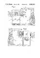
- FIG. 1is a plan view of a manipulator with an associated industrial robot
- FIG. 2is a section taken along the line II--II in FIG. 1;
- FIG. 3is an end view of the manipulator and the robot as seen from the upper end of FIG. 1;
- FIG. 4is a partial side view, partly in section, and seen from the line IV--IV in FIG. 2;
- FIG. 5is a section as seen from the line V--V in FIG. 1;
- FIG. 6is a detail view, partly in section, of the clutch between the turning motor and the fixture support showing the clutch members disengaged;
- FIG. 7is a corresponding detail view showing the clutch members in mutually engaged position.
- numeral 1designates in general a manipulator according to the invention which cooperates with an industrial robot 2 which is stationarily located in relation to the manipulator 1 by the fact that its base is through base beams 3 connected to corresponding base beams 4 of the manipulator 1.
- the industrial robot 2is of the type having an implement supporting arm 2' which may be swung horizontally as well as vertically and, in addition, may be moved in its longitudinal direction to wield an implement, not shown, over a workpiece 5 supported by the manipulator and indicated by dash-and-dot lines.
- the detailed design of the industrial robot 2is irrelevant to the invention, but it should be clear that the same in known manner is adapted to operate according to a predetermined program accommodated to the workpiece at hand, said program also including control of the manipulator.
- the manipulator 1comprises a main stand 6 and a secondary stand 7 secured to opposite ends of the base beams 4 and supporting between them a generally H-shaped holder 8, which is rotatable about a horizontal main axis represented by pivots 9 and 9' journalled in bearings 10 supported by the stands 6 and 7.
- the holder 8has a tubular central portion 8' extending parallel to the main axis of the holder, and a pair of likewise tubular transversely extending arms 8" and 8"', respectively, which are arranged at the respective ends of the central portion and project in opposite directions therefrom.
- a pin 11which is adapted to cooperate with stops 12 mounted on the side of the main stand 6 facing the holder for limiting the rotational movement of the holder 8.
- a reversible electric motor 13 supported by the main stand 6 and the operation of which in a suitable manner is co-ordinated with the operational program of the robot 2serves through a sliding clutch 14 to rotate the holder 8 to and fro approximately 180° about the main axis 9-9' such that the pin 11 is caused to alternatingly abut against the one or the other of the two stops 12.
- two first fixture supporting plates 15A and 15Bare rotatably mounted at equal distances from the main axis 9-9' of the holder, and this in such a manner that the axes of rotation of the two fixture supporting plates 15A and 15B are parallel to said main axis and like the same extend horizontally.
- the fixture supporting plates 15A and 15Bare arranged on the inside of the holder arm 8" turned away from the main stand 6, and through a related shaft each fixture supporting plate is non-rotatably secured to a corresponding clutch plate 16A and 16B, respectively, which is located on the outside of the arm 8" facing the main stand 6.
- a drive plate 17is adapted to engage one of the two clutch plates 16A and 16B at a time.
- the drive plate 17is secured on the shaft of a turning motor 18, the rotational movements of which through a known, but not shown, electrical control system are co-ordinated with the operational movements of the robot 2.
- the turning motor 18may, of course, be permanently connected to the control system of the robot as it is common to both the two fixture supporting plates 15A and 15B.
- the turning motor 18is fastened on a slide 19 which under the actuation of a moving mechanism 20--represented in the example shown by a double-acting pneumatic cylinder, see FIG. 4--is movable in the axial direction of the turning motor along a rectilinear guide 21 which is mounted on a shelf 22 mounted on one side of the main stand 6.
- each clutch plate 16A and 16Brespectively, has a central hole 27 which is at least partly conical in shape and which is adapted to receive a likewise partially conical central pin 28 on the drive plate 17, the task of which is to accurately center the clutch plate relative to the turning motor 18 and thus determine the accurate position for the axis of rotation about which the workpiece 5 will be turned by means of the turning motor 18 during the operation of the industrial robot 2. This means that no high demands on accuracy are made on the swinging movements which the motor 13 imparts to the holder 8.
- the drive plate 17is further provided with an eccentrically arranged drive pin 29 which, when the clutch members are engaged, enters the bore 25 and in doing so pushes away the locking pin 23, as shown in FIG.
- each second fixture supporting plate 30A and 30Bis through a chain transmission 31 housed within the holder arm 8"' connected to an auxiliary shaft 32A and 32B, respectively, rotatably mounted in the central portion 8' of the holder 8 and being through a second chain transmission 33 housed in the holder arm 8" connected to the corresponding first fixture supporting plate 15A and 15B, respectively.
- each pair of opposite fixture supporting plates 15A and 30A as well as 15B and 30Bis permanent and assures that the two plates in each pair will be synchronously turned under the actuation of the turning motor 18 such that they may between them support parts of a common workpiece which for example are to be welded together by means of the robot 2.
- the two auxiliary shafts 32A and 32Bare parallel with the main axis 9, 9' of the holder 8.
- the mode of operation of the manipulatoris as follows: After a new workpiece or parts of the same have been fastened between the fixture supporting plates 15A and 30A which are assumed to be in the left hand position as shown in FIG. 1, the so-called loading position, the holder 8 is by means of the motor 13 rotated half a revolution such that the workpiece is moved to the so-called operative position within the operating range of the robot 2, which may in certain cases necessitate the folding up of the implement supporting arm 2' of the robot. Thereafter the moving mechanism 20 of the slide 19 is activated such that the turning motor 18 is axially moved in the downward direction in FIG.
- the industrial robot 2may carry out its operation in co-ordination with the turning motor 18 which sees to it that desired portions of the workpiece become accessible to the implement of the robot. During the time the robot is in operation a new workpiece is mounted between the two other fixture supporting plates 15B and 30B of the holder 8.
- the moving mechanism 20is again activated, but in the opposite direction as compared with before in order to make the drive plate 17 disengage the clutch plate 16A.
- the clutch membershave been disengaged the holder 8 is again rotated approximately half a revolution by means of the motor 13 but this time in the opposite direction as compared with before, the newly mounted workpiece being thus moved into the operative position within the operating range of the robot whereas the completed workpiece is moved to the loading position and may be detached in order to be replaced by a further new workpiece.
- the cooperating clutch membersi.e., the clutch plates 16 and the drive plate 17 may with unaltered basic operation be given another detail design.
- the two auxiliary shafts 32A and 32Bmay, of course, be concentric, one tubularly surrounding the other.
- the guide and the moving mechanism of the turning motor 18may be designed in various different ways.
Landscapes
- Engineering & Computer Science (AREA)
- Mechanical Engineering (AREA)
- Physics & Mathematics (AREA)
- Optics & Photonics (AREA)
- Robotics (AREA)
- Manipulator (AREA)
Abstract
Description
Claims (10)
Applications Claiming Priority (2)
| Application Number | Priority Date | Filing Date | Title |
|---|---|---|---|
| SE8402122 | 1984-04-16 | ||
| SE8402122ASE437627B (en) | 1984-04-16 | 1984-04-16 | MANIPULATOR FOR COOPERATION WITH AN INDUSTRIAL ROBOT |
Publications (1)
| Publication Number | Publication Date |
|---|---|
| US4666363Atrue US4666363A (en) | 1987-05-19 |
Family
ID=20355599
Family Applications (1)
| Application Number | Title | Priority Date | Filing Date |
|---|---|---|---|
| US06/721,623Expired - Fee RelatedUS4666363A (en) | 1984-04-16 | 1985-04-10 | Manipulator for cooperation with an industrial robot |
Country Status (3)
| Country | Link |
|---|---|
| US (1) | US4666363A (en) |
| CA (1) | CA1241681A (en) |
| SE (1) | SE437627B (en) |
Cited By (21)
| Publication number | Priority date | Publication date | Assignee | Title |
|---|---|---|---|---|
| US4764077A (en)* | 1986-04-18 | 1988-08-16 | Thermwood Corporation | Assembly for performing work functions on a workpiece |
| US5074741A (en)* | 1990-02-12 | 1991-12-24 | Torsteknik Ab | Manipulator intended for cooperation with an industrial robot |
| EP0744244A1 (en)* | 1995-05-24 | 1996-11-27 | Ditta Bacci Paolino Di Giuseppe Bacci Di Agostino Bacci | Machine tool for the machining of elongated elements with cantilever-mounted workpiece holder |
| US6264418B1 (en) | 1998-03-30 | 2001-07-24 | Motoman, Inc. | Workpiece positioner |
| US6281474B1 (en) | 1999-08-17 | 2001-08-28 | Motoman, Inc. | X-beam positioner |
| US6641667B2 (en)* | 2000-08-29 | 2003-11-04 | Honda Giken Kogyo Kabushiki Kaisha | Robot-mounted two-package-mixing coating device and internal pressure explosion-proof robot |
| US20030214087A1 (en)* | 2002-05-17 | 2003-11-20 | Comau S.P.A. | Equipment which can be used by an industrial robot for gripping workpieces or assemblies being processed or assembled and has a separable modular structure, with a definite and repeatable geometry |
| FR2850046A1 (en)* | 2003-01-22 | 2004-07-23 | Sauvageau Commercy Soudure | Welding installation, especially robot-controlled, has barrel and holder motors with clutches and indexing/de-indexing system |
| US7172376B1 (en)* | 2006-01-24 | 2007-02-06 | Progressive Systems, Inc. | Workpiece positioner |
| US20080046120A1 (en)* | 2006-08-15 | 2008-02-21 | Jan Christian Mangelsen | Modular robotic workpiece holder and method for using same |
| CN102000929A (en)* | 2010-10-27 | 2011-04-06 | 长城汽车股份有限公司 | Automatic welding device of circular weld beads |
| US20130038070A1 (en)* | 2010-02-16 | 2013-02-14 | Kurt Andersen | Method for assembling part of a generator, generator and wind turbine |
| WO2014035352A1 (en)* | 2012-08-29 | 2014-03-06 | Gokhan Vargin Gok | A positioner with angular wings |
| JP2014507293A (en)* | 2011-01-26 | 2014-03-27 | ヴァルター マシーネンバウ ゲーエムベーハー | Machine for workpiece machining and / or measurement with two pivotable transverse members |
| WO2014058397A1 (en)* | 2012-10-12 | 2014-04-17 | Gök Gökhan Vargin | Single axis and two station gear positioner |
| US9372160B2 (en)* | 2011-05-17 | 2016-06-21 | Gii Acquisition, Llc | Method and system for optically inspecting the ends of a manufactured part at a single inspection station having a measurement axis |
| US20160231253A1 (en)* | 2011-05-17 | 2016-08-11 | Gii Acquisition, Llc Dba General Inspection, Llc | Method and system for optically inspecting parts |
| US10520933B2 (en)* | 2018-04-13 | 2019-12-31 | The Boeing Company | System and method for removing a workpiece from a manufacturing fixture |
| WO2022063394A1 (en)* | 2020-09-23 | 2022-03-31 | Abb Schweiz Ag | Positioning apparatus and system |
| WO2022164939A1 (en)* | 2021-01-28 | 2022-08-04 | Yaskawa America Inc. | Workpiece positioner assembly having compliance assemblies |
| US12440934B2 (en) | 2020-09-23 | 2025-10-14 | Abb Schweiz Ag | Positioning apparatus and system |
Families Citing this family (2)
| Publication number | Priority date | Publication date | Assignee | Title |
|---|---|---|---|---|
| CN111152044A (en)* | 2020-02-02 | 2020-05-15 | 罗夯智能科技(上海)有限公司 | Four-station horizontal type exchange workbench device |
| CN111152043A (en)* | 2020-02-02 | 2020-05-15 | 罗夯智能科技(上海)有限公司 | Auxiliary supporting mechanism for rotary table |
Citations (3)
| Publication number | Priority date | Publication date | Assignee | Title |
|---|---|---|---|---|
| US4014495A (en)* | 1974-02-22 | 1977-03-29 | Shin Meiwa Industry Co., Ltd. | Automatic welding apparatus |
| DE2849126A1 (en)* | 1977-11-23 | 1979-06-07 | Polytype Ag | PROCEDURE AND DEVICE FOR POSITIONING TUBES, SLEEVES AND SIMILAR HOLLOW BODIES |
| US4406576A (en)* | 1980-08-05 | 1983-09-27 | Fujitsu Fanuc Limited | Industrial robot with a safeguard mechanism |
- 1984
- 1984-04-16SESE8402122Apatent/SE437627B/ennot_activeIP Right Cessation
- 1985
- 1985-04-10USUS06/721,623patent/US4666363A/ennot_activeExpired - Fee Related
- 1985-04-15CACA000479122Apatent/CA1241681A/ennot_activeExpired
Patent Citations (3)
| Publication number | Priority date | Publication date | Assignee | Title |
|---|---|---|---|---|
| US4014495A (en)* | 1974-02-22 | 1977-03-29 | Shin Meiwa Industry Co., Ltd. | Automatic welding apparatus |
| DE2849126A1 (en)* | 1977-11-23 | 1979-06-07 | Polytype Ag | PROCEDURE AND DEVICE FOR POSITIONING TUBES, SLEEVES AND SIMILAR HOLLOW BODIES |
| US4406576A (en)* | 1980-08-05 | 1983-09-27 | Fujitsu Fanuc Limited | Industrial robot with a safeguard mechanism |
Cited By (27)
| Publication number | Priority date | Publication date | Assignee | Title |
|---|---|---|---|---|
| US4764077A (en)* | 1986-04-18 | 1988-08-16 | Thermwood Corporation | Assembly for performing work functions on a workpiece |
| US5074741A (en)* | 1990-02-12 | 1991-12-24 | Torsteknik Ab | Manipulator intended for cooperation with an industrial robot |
| EP0442160A3 (en)* | 1990-02-12 | 1992-12-09 | Torsteknik Ab | A manipulator intended for cooperation with an industrial robot |
| EP0744244A1 (en)* | 1995-05-24 | 1996-11-27 | Ditta Bacci Paolino Di Giuseppe Bacci Di Agostino Bacci | Machine tool for the machining of elongated elements with cantilever-mounted workpiece holder |
| US6264418B1 (en) | 1998-03-30 | 2001-07-24 | Motoman, Inc. | Workpiece positioner |
| US6281474B1 (en) | 1999-08-17 | 2001-08-28 | Motoman, Inc. | X-beam positioner |
| US6641667B2 (en)* | 2000-08-29 | 2003-11-04 | Honda Giken Kogyo Kabushiki Kaisha | Robot-mounted two-package-mixing coating device and internal pressure explosion-proof robot |
| US20030214087A1 (en)* | 2002-05-17 | 2003-11-20 | Comau S.P.A. | Equipment which can be used by an industrial robot for gripping workpieces or assemblies being processed or assembled and has a separable modular structure, with a definite and repeatable geometry |
| US6802499B2 (en)* | 2002-05-17 | 2004-10-12 | Comau S.P.A. | Equipment which can be used by an industrial robot for gripping workpieces or assemblies being processed or assembled and has a separable modular structure, with a definite and repeatable geometry |
| FR2850046A1 (en)* | 2003-01-22 | 2004-07-23 | Sauvageau Commercy Soudure | Welding installation, especially robot-controlled, has barrel and holder motors with clutches and indexing/de-indexing system |
| US7172376B1 (en)* | 2006-01-24 | 2007-02-06 | Progressive Systems, Inc. | Workpiece positioner |
| US20080046120A1 (en)* | 2006-08-15 | 2008-02-21 | Jan Christian Mangelsen | Modular robotic workpiece holder and method for using same |
| US8146901B2 (en)* | 2006-08-15 | 2012-04-03 | Genesis Systems Group, Llc | Modular robotic workpiece holder and method for using same |
| US20130038070A1 (en)* | 2010-02-16 | 2013-02-14 | Kurt Andersen | Method for assembling part of a generator, generator and wind turbine |
| CN102000929A (en)* | 2010-10-27 | 2011-04-06 | 长城汽车股份有限公司 | Automatic welding device of circular weld beads |
| JP2014507293A (en)* | 2011-01-26 | 2014-03-27 | ヴァルター マシーネンバウ ゲーエムベーハー | Machine for workpiece machining and / or measurement with two pivotable transverse members |
| US9372160B2 (en)* | 2011-05-17 | 2016-06-21 | Gii Acquisition, Llc | Method and system for optically inspecting the ends of a manufactured part at a single inspection station having a measurement axis |
| US20160231253A1 (en)* | 2011-05-17 | 2016-08-11 | Gii Acquisition, Llc Dba General Inspection, Llc | Method and system for optically inspecting parts |
| US9697596B2 (en)* | 2011-05-17 | 2017-07-04 | Gii Acquisition, Llc | Method and system for optically inspecting parts |
| WO2014035352A1 (en)* | 2012-08-29 | 2014-03-06 | Gokhan Vargin Gok | A positioner with angular wings |
| WO2014058397A1 (en)* | 2012-10-12 | 2014-04-17 | Gök Gökhan Vargin | Single axis and two station gear positioner |
| US10520933B2 (en)* | 2018-04-13 | 2019-12-31 | The Boeing Company | System and method for removing a workpiece from a manufacturing fixture |
| WO2022063394A1 (en)* | 2020-09-23 | 2022-03-31 | Abb Schweiz Ag | Positioning apparatus and system |
| CN116209546A (en)* | 2020-09-23 | 2023-06-02 | Abb瑞士股份有限公司 | Positioning device and system |
| US12440934B2 (en) | 2020-09-23 | 2025-10-14 | Abb Schweiz Ag | Positioning apparatus and system |
| WO2022164939A1 (en)* | 2021-01-28 | 2022-08-04 | Yaskawa America Inc. | Workpiece positioner assembly having compliance assemblies |
| US12162097B2 (en) | 2021-01-28 | 2024-12-10 | Yaskawa America, Inc. | Workpiece positioner assembly having compliance assemblies |
Also Published As
| Publication number | Publication date |
|---|---|
| CA1241681A (en) | 1988-09-06 |
| SE8402122D0 (en) | 1984-04-16 |
| SE437627B (en) | 1985-03-11 |
Similar Documents
| Publication | Publication Date | Title |
|---|---|---|
| US4666363A (en) | Manipulator for cooperation with an industrial robot | |
| US5074741A (en) | Manipulator intended for cooperation with an industrial robot | |
| US3885678A (en) | Material handling apparatus | |
| US20080226436A1 (en) | Manipulation device and production system | |
| US3857496A (en) | Placement robot providing a vertical and horizontal displacement output | |
| US4439090A (en) | Workpiece handling apparatus | |
| EP0063161A1 (en) | Industrial robot | |
| CN108568833A (en) | Holder driver and clamper | |
| US4125072A (en) | Workpiece turning device | |
| US5628104A (en) | Machine tool with turntable | |
| GB2131390A (en) | Automatic handling implement for industrial operations | |
| CN208468412U (en) | Holder driver and clamper | |
| EP0377865B1 (en) | Punching and nibbling machine fitted with a device for an automatic quick tool change | |
| US5261148A (en) | Rotary vice for rotary table | |
| US3990585A (en) | Article exchange mechanism | |
| US6250999B1 (en) | Multi-spindle lapping machine | |
| US5855541A (en) | Machine tool | |
| JPH0751234Y2 (en) | Eccentric processing device | |
| CA1136926A (en) | Positioning apparatus | |
| CN222021633U (en) | Snatch mechanism and have its robot | |
| EP0242771B1 (en) | Bottle-manufacturing apparatus | |
| WO1991003335A1 (en) | Turret punch press | |
| SU1673397A1 (en) | Flexible manufacturing system | |
| SU1495055A1 (en) | Apparatus for moving articles | |
| US5088182A (en) | Turret changer |
Legal Events
| Date | Code | Title | Description |
|---|---|---|---|
| AS | Assignment | Owner name:HOBART BROTHERS COMPANY, 600 WEST MAIN STREET, TRO Free format text:ASSIGNMENT OF ASSIGNORS INTEREST.;ASSIGNOR:JOHANSSON, JOHN I.E.;REEL/FRAME:004394/0108 Effective date:19850401 | |
| FEPP | Fee payment procedure | Free format text:PAYOR NUMBER ASSIGNED (ORIGINAL EVENT CODE: ASPN); ENTITY STATUS OF PATENT OWNER: SMALL ENTITY | |
| FPAY | Fee payment | Year of fee payment:4 | |
| FEPP | Fee payment procedure | Free format text:PAT HOLDER CLAIMS SMALL ENTITY STATUS - SMALL BUSINESS (ORIGINAL EVENT CODE: SM02); ENTITY STATUS OF PATENT OWNER: SMALL ENTITY | |
| AS | Assignment | Owner name:MOTOMAN ROBOTICS AB, SWEDEN Free format text:ASSIGNMENT OF ASSIGNORS INTEREST;ASSIGNOR:HOBART BROTHERS COMPANY;REEL/FRAME:007194/0658 Effective date:19941031 | |
| FPAY | Fee payment | Year of fee payment:8 | |
| FEPP | Fee payment procedure | Free format text:PAYER NUMBER DE-ASSIGNED (ORIGINAL EVENT CODE: RMPN); ENTITY STATUS OF PATENT OWNER: SMALL ENTITY Free format text:PAYOR NUMBER ASSIGNED (ORIGINAL EVENT CODE: ASPN); ENTITY STATUS OF PATENT OWNER: SMALL ENTITY | |
| REMI | Maintenance fee reminder mailed | ||
| LAPS | Lapse for failure to pay maintenance fees | ||
| FP | Lapsed due to failure to pay maintenance fee | Effective date:19990519 | |
| STCH | Information on status: patent discontinuation | Free format text:PATENT EXPIRED DUE TO NONPAYMENT OF MAINTENANCE FEES UNDER 37 CFR 1.362 |