US4666149A - Multi-exercise system - Google Patents
Multi-exercise systemDownload PDFInfo
- Publication number
- US4666149A US4666149AUS06/765,693US76569385AUS4666149AUS 4666149 AUS4666149 AUS 4666149AUS 76569385 AUS76569385 AUS 76569385AUS 4666149 AUS4666149 AUS 4666149A
- Authority
- US
- United States
- Prior art keywords
- lower portion
- resistive force
- exercise system
- recited
- bar
- Prior art date
- Legal status (The legal status is an assumption and is not a legal conclusion. Google has not performed a legal analysis and makes no representation as to the accuracy of the status listed.)
- Expired - Lifetime
Links
- 238000006073displacement reactionMethods0.000claimsdescription24
- 230000008878couplingEffects0.000claimsdescription12
- 238000010168coupling processMethods0.000claimsdescription12
- 238000005859coupling reactionMethods0.000claimsdescription12
- 230000007246mechanismEffects0.000abstractdescription91
- 238000003780insertionMethods0.000description3
- 230000037431insertionEffects0.000description3
- 229910000831SteelInorganic materials0.000description2
- 229910052782aluminiumInorganic materials0.000description2
- XAGFODPZIPBFFR-UHFFFAOYSA-NaluminiumChemical compound[Al]XAGFODPZIPBFFR-UHFFFAOYSA-N0.000description2
- 239000010959steelSubstances0.000description2
- 238000006243chemical reactionMethods0.000description1
- 239000000463materialSubstances0.000description1
- 229910052751metalInorganic materials0.000description1
- 239000002184metalSubstances0.000description1
- 239000000203mixtureSubstances0.000description1
- 238000012986modificationMethods0.000description1
- 230000004048modificationEffects0.000description1
- 230000002441reversible effectEffects0.000description1
- 238000003466weldingMethods0.000description1
Images


Classifications
- A—HUMAN NECESSITIES
- A63—SPORTS; GAMES; AMUSEMENTS
- A63B—APPARATUS FOR PHYSICAL TRAINING, GYMNASTICS, SWIMMING, CLIMBING, OR FENCING; BALL GAMES; TRAINING EQUIPMENT
- A63B21/00—Exercising apparatus for developing or strengthening the muscles or joints of the body by working against a counterforce, with or without measuring devices
- A—HUMAN NECESSITIES
- A63—SPORTS; GAMES; AMUSEMENTS
- A63B—APPARATUS FOR PHYSICAL TRAINING, GYMNASTICS, SWIMMING, CLIMBING, OR FENCING; BALL GAMES; TRAINING EQUIPMENT
- A63B23/00—Exercising apparatus specially adapted for particular parts of the body
- A—HUMAN NECESSITIES
- A63—SPORTS; GAMES; AMUSEMENTS
- A63B—APPARATUS FOR PHYSICAL TRAINING, GYMNASTICS, SWIMMING, CLIMBING, OR FENCING; BALL GAMES; TRAINING EQUIPMENT
- A63B21/00—Exercising apparatus for developing or strengthening the muscles or joints of the body by working against a counterforce, with or without measuring devices
- A63B21/00058—Mechanical means for varying the resistance
- A63B21/00069—Setting or adjusting the resistance level; Compensating for a preload prior to use, e.g. changing length of resistance or adjusting a valve
- A63B21/00072—Setting or adjusting the resistance level; Compensating for a preload prior to use, e.g. changing length of resistance or adjusting a valve by changing the length of a lever
- A—HUMAN NECESSITIES
- A63—SPORTS; GAMES; AMUSEMENTS
- A63B—APPARATUS FOR PHYSICAL TRAINING, GYMNASTICS, SWIMMING, CLIMBING, OR FENCING; BALL GAMES; TRAINING EQUIPMENT
- A63B21/00—Exercising apparatus for developing or strengthening the muscles or joints of the body by working against a counterforce, with or without measuring devices
- A63B21/02—Exercising apparatus for developing or strengthening the muscles or joints of the body by working against a counterforce, with or without measuring devices using resilient force-resisters
- A63B21/04—Exercising apparatus for developing or strengthening the muscles or joints of the body by working against a counterforce, with or without measuring devices using resilient force-resisters attached to static foundation, e.g. a user
- A—HUMAN NECESSITIES
- A63—SPORTS; GAMES; AMUSEMENTS
- A63B—APPARATUS FOR PHYSICAL TRAINING, GYMNASTICS, SWIMMING, CLIMBING, OR FENCING; BALL GAMES; TRAINING EQUIPMENT
- A63B21/00—Exercising apparatus for developing or strengthening the muscles or joints of the body by working against a counterforce, with or without measuring devices
- A63B21/02—Exercising apparatus for developing or strengthening the muscles or joints of the body by working against a counterforce, with or without measuring devices using resilient force-resisters
- A63B21/055—Exercising apparatus for developing or strengthening the muscles or joints of the body by working against a counterforce, with or without measuring devices using resilient force-resisters extension element type
- A63B21/0552—Elastic ropes or bands
- A—HUMAN NECESSITIES
- A63—SPORTS; GAMES; AMUSEMENTS
- A63B—APPARATUS FOR PHYSICAL TRAINING, GYMNASTICS, SWIMMING, CLIMBING, OR FENCING; BALL GAMES; TRAINING EQUIPMENT
- A63B21/00—Exercising apparatus for developing or strengthening the muscles or joints of the body by working against a counterforce, with or without measuring devices
- A63B21/15—Arrangements for force transmissions
- A63B21/151—Using flexible elements for reciprocating movements, e.g. ropes or chains
- A63B21/154—Using flexible elements for reciprocating movements, e.g. ropes or chains using special pulley-assemblies
- A—HUMAN NECESSITIES
- A63—SPORTS; GAMES; AMUSEMENTS
- A63B—APPARATUS FOR PHYSICAL TRAINING, GYMNASTICS, SWIMMING, CLIMBING, OR FENCING; BALL GAMES; TRAINING EQUIPMENT
- A63B21/00—Exercising apparatus for developing or strengthening the muscles or joints of the body by working against a counterforce, with or without measuring devices
- A63B21/40—Interfaces with the user related to strength training; Details thereof
- A63B21/4041—Interfaces with the user related to strength training; Details thereof characterised by the movements of the interface
- A63B21/4047—Pivoting movement
- A—HUMAN NECESSITIES
- A63—SPORTS; GAMES; AMUSEMENTS
- A63B—APPARATUS FOR PHYSICAL TRAINING, GYMNASTICS, SWIMMING, CLIMBING, OR FENCING; BALL GAMES; TRAINING EQUIPMENT
- A63B21/00—Exercising apparatus for developing or strengthening the muscles or joints of the body by working against a counterforce, with or without measuring devices
- A63B21/00058—Mechanical means for varying the resistance
- A63B21/00065—Mechanical means for varying the resistance by increasing or reducing the number of resistance units
- A—HUMAN NECESSITIES
- A63—SPORTS; GAMES; AMUSEMENTS
- A63B—APPARATUS FOR PHYSICAL TRAINING, GYMNASTICS, SWIMMING, CLIMBING, OR FENCING; BALL GAMES; TRAINING EQUIPMENT
- A63B21/00—Exercising apparatus for developing or strengthening the muscles or joints of the body by working against a counterforce, with or without measuring devices
- A63B21/00058—Mechanical means for varying the resistance
- A63B21/00069—Setting or adjusting the resistance level; Compensating for a preload prior to use, e.g. changing length of resistance or adjusting a valve
- A—HUMAN NECESSITIES
- A63—SPORTS; GAMES; AMUSEMENTS
- A63B—APPARATUS FOR PHYSICAL TRAINING, GYMNASTICS, SWIMMING, CLIMBING, OR FENCING; BALL GAMES; TRAINING EQUIPMENT
- A63B21/00—Exercising apparatus for developing or strengthening the muscles or joints of the body by working against a counterforce, with or without measuring devices
- A63B21/02—Exercising apparatus for developing or strengthening the muscles or joints of the body by working against a counterforce, with or without measuring devices using resilient force-resisters
- A63B21/04—Exercising apparatus for developing or strengthening the muscles or joints of the body by working against a counterforce, with or without measuring devices using resilient force-resisters attached to static foundation, e.g. a user
- A63B21/0407—Anchored at two end points, e.g. installed within an apparatus
- A63B21/0428—Anchored at two end points, e.g. installed within an apparatus the ends moving relatively by linear reciprocation
- A—HUMAN NECESSITIES
- A63—SPORTS; GAMES; AMUSEMENTS
- A63B—APPARATUS FOR PHYSICAL TRAINING, GYMNASTICS, SWIMMING, CLIMBING, OR FENCING; BALL GAMES; TRAINING EQUIPMENT
- A63B21/00—Exercising apparatus for developing or strengthening the muscles or joints of the body by working against a counterforce, with or without measuring devices
- A63B21/02—Exercising apparatus for developing or strengthening the muscles or joints of the body by working against a counterforce, with or without measuring devices using resilient force-resisters
- A63B21/055—Exercising apparatus for developing or strengthening the muscles or joints of the body by working against a counterforce, with or without measuring devices using resilient force-resisters extension element type
- A63B21/0552—Elastic ropes or bands
- A63B21/0557—Details of attachments, e.g. clips or clamps
- A—HUMAN NECESSITIES
- A63—SPORTS; GAMES; AMUSEMENTS
- A63B—APPARATUS FOR PHYSICAL TRAINING, GYMNASTICS, SWIMMING, CLIMBING, OR FENCING; BALL GAMES; TRAINING EQUIPMENT
- A63B2208/00—Characteristics or parameters related to the user or player
- A63B2208/02—Characteristics or parameters related to the user or player posture
- A63B2208/0228—Sitting on the buttocks
Definitions
- This inventionis directed to a multi-exercise system.
- this inventionis directed to a multi-exercise system wherein a user may exercise different portions of his or her body and allows adjustability of the system to differing physical characteristics of the user.
- this inventionis directed to a multi-exercise system which includes a rotatively actuated bar mechanism utilized in combination with a rotational actuation mechanism rotatable about a singular axis.
- this inventionis directed to a multi-exercise system which includes a resistive force mechanism adjustable and fixedly securable to a pair of vertically directed bar frame members.
- this inventionrelates to a multi-exercise system where the rotational actuation mechanism is coupled to a resistive force mechanism composed of an upper portion having a singular pulley for translating user rotational actuation to a linear displacement. More in particular, this invention pertains to the multi-exercise system where the resistive force mechanism includes an upper portion as well as a first and second lower portion wherein the second lower portion is fixedly secured to the upper portion of the resistive force mechanism and the first lower portion is displaceable with respect to the resistive force second lower portion responsive to a rotative actuation by the user.
- the rotational actuation of the user applied forceis adjustable through the use of placing weight elements on or off of the displacing mechanism.
- Such prior art systemsdo not allow for the user to adjust the resistive force by mere insertion of a pin member into one or more of a plurality of resistive force load coupling mechanisms.
- a multi-exercise systemfor providing a resistive force loading responsive to an applied force by a user.
- the multi-exercise systemincludes a base frame having at least a pair of substantially vertically elongated and horizontally displaced base bar frame members.
- a resistive force mechanismis fixedly securable to at least one of the base bar frame members for transferring the user applied force to the resistive force loading.
- a rotational actuation mechanismis coupled to an upper portion of the resistive force mechanism for linearly displacing a first lower portion of the resistive force mechanism with respect to a second lower portion of the resistive force mechanism responsive to a rotational actuation force applied by the user.
- FIG. 1is a frontal view of the multi-exercise system
- FIG. 2is a frontal view partially in cut-away of the multi-exercise system showing the resistive force mechanism
- FIG. 3is a perspective view partially in cut-away showing the actuating bar mechanism for the multi-exercise system
- FIG. 4is a frontal view, partially in cut-away of the rotational actuation mechanism in combination with the resistive force mechanism of the multi-exercise system;
- FIG. 5is a sectional view partially in cut-away of the multi-exercise system taken along the section lines 5--5 of FIG. 4;
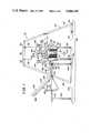
- FIG. 6is a sectional view, partially in cut-away of the rotational actuation mechanism taken along the section line 6--6 of FIG. 2;
- FIG. 7is a sectional view partially in cut-away of the resistive force mechanism taken along the section line 7--7 of FIG. 2;
- FIG. 8is a sectional view of the resistive force mechanism taken along the section line 8--8 of FIG. 2.
- multi-exercise system 10for providing a resistive force loading responsive to an applied force by a user.
- multi-exercise system 10allows the user to apply a rotational displacement to pad member 12 shown in FIGS. 1 and 6, in the direction of arcuate directional arrow 14. Through this displacement, as will be seen in following paragraphs, the rotational displacement of pad member 12 in direction 14 results in a rotational to linear displacement transfer which acts on a resistive force within the system to provide exercise for the user.
- system 10is directed in general concept to an exercising mechanism which provides for a wide variety of exercises for the user and further allows adjustability in the mechanisms to increase the number of exercises and the applicability to a wide range of user physical characteristics. Still further, multi-exercise system 10 allows for a simplified mechanism where the rotary displacement applied by the user is transferred to a linear displacement mechanism through rotation about singular axis 16. Utilization of singular axis 16 provides for a simplified mechanism for multi-exercise system 10 than is known for prior art systems.
- Multi-exercise system 10includes base frame 24 for interfacing with base surface 22 in order to provide system 10 with a stable platform upon which the working mechanisms may be actuated.
- Base frame 24may include system floor structural members 30 which extend in horizontal or transverse direction 20 and contiguously interface with base surface 22.
- Opposing inclined system structural members 26 and 28extend in an inclined and vertical direction 18 for coupling with system upper structural members 32 which pass in horizontal direction 20.
- Structural members 26, 28, 30 and 32are coupled each to the other through structural bolts 34 or some like mechanism, such as welding, however, such is not important to the inventive concept as herein described, with the exception that the associated structural members be coupled each to the other in a substantially rigid manner and acceptable for the structural loads imposed thereon.
- System structural members 26, 28, 30 and 32may be formed of steel channels, tubing, angle-irons, or some like configuration not important to the inventive concept as herein described. Additionally, the afore-mentioned structural members 26-32 may be formed of aluminum or some like metal or other material where the only restriction is that such provide sufficient structural integrity to accept the loads applied by system 10 as well as the applied forces by the user.
- Base bar frame members 36 and 38extending in vertical direction 18 and displaced each from the other in horizontal direction 20.
- Base bar frame members 36 and 38are important to the inventive concept as herein described, since such provide for a displacement frame section upon which operating mechanisms are displaceably actuated as will be described in following paragraphs.
- Base bar frame members 36 and 38 as seen in FIG. 1are secured to system floor structural member 30 and system upper structural member 32 through bolts 34.
- Frame members 36 and 38may be formed of metallic tubing or some like configuration, and formed of steel, aluminum, or some like metallic composition, not important to the inventive concept as herein described, with the exception that such provide for structural integrity responsive to the loads imposed thereon.
- resistive force mechanism 40which is adapted to be fixedly secured to base bar frame members 36 and 38 as well as displaceable with respect thereto and is used for transferring user applied force to the resistive force loading.
- Resistive force mechanism 40includes resistive force mechanism upper portion 42 and resistive force mechanism lower portion 44.
- Resistive force mechanism lower portion 44includes resistive force mechanism first lower portion 46 and resistive force mechanism second lower portion 48, as is shown in FIG. 4.
- Resistive force mechanism second lower portion 48is fixedly secured to resistive force mechanism upper portion 42 and are secured each to the other by resistive force tubular members 50 and 52 which pass around and are slidably displaceable with respect to base bar frame members 36 and 38.
- resistive force mechanism upper portion 42may be welded or otherwise coupled to resistive force tubular member 50, as is shown in FIG. 4.
- Tubular member 50(as well as tubular member 52) passes in vertical direction 18 to resistive force mechanism second lower portion 48 where such is welded or otherwise coupled to second lower portion bar member 54 forming part of resistive force mechanism second lower portion 48.
- Second lower portion bar member 54extends in transverse or horizontal direction 20 and is fixedly secured on opposing ends thereof to resistive force tubular members 50 and 52.
- resistive force mechanism upper portion 42is transmitted through resistive force tubular members 50 and 52 and correspondingly and responsively, displaces resistive force mechanism second lower portion 48 and in particular, second lower portion bar member 54.
- upper portion 42 and resistive force mechanism second lower portion 48slidingly or otherwise displacingly pass over base bar frame members 36 and 38.
- second lower portion bar member 54may be formed in a channel-like configuration, as is clearly seen in FIG. 5.
- upper and second lower portions of resistive force means 42 and 48are vertically displaceable with respect to base bar frame members 36 and 38, as a unit.
- Resistive force mechanism second lower portion 48includes second lower portion housing member 56 which is vertically secured to and vertically displaced from second lower portion bar member 54.
- Second lower portion housing member 56is rigidly and fixedly secured to second lower portion bar member 54 by connecting structural members 58 and 60 which extend in vertical direction 18 and are welded or otherwise fixedly secured on opposing ends thereof to second lower portion housing member 56 and second lower portion bar member 54.
- the coupling and configuration for members 56 and 54is clearly seen in FIG. 2. In this manner, it is seen that vertical displacement of resistive force mechanism upper portion 42 results in a corresponding and responsive vertical displacement of second lower portion bar member 54 as well as the identical displacement of second lower portion housing member 56, since all of these component elements are rigidly coupled each to the other.
- Resistive force mechanism 40further includes first lower portion housing member 62 which is displaceably coupled to second lower portion bar member 54 as well as it is displaceably coupled to upper portion 42.
- First lower portion housing member 62is clearly seen in FIGS. 2, 4 and 5.
- First lower portion housing member 62may be generally U-shaped in contour, as is seen in FIG. 2, and formed of horizontally directed channel member 64 rigidly secured on opposing horizontal ends to vertically directed housing channel members 66 and 68.
- vertically directed housing channel members 66 and 68pass around resistive force tubular members 50 and 52 and are displaceable with respect thereto through roller members 70.
- first lower portion housing member 62may be displaceably actuated with respect to second lower portion housing member 56 from a contiguous position shown in FIGS. 4 and 5 to a displaced position as is shown in FIG. 2.
- first lower portion housing member 62when first lower portion housing member 62 is in contiguous contact with second lower portion housing member 56 and second lower portion bar member 54, vertical movement or displacement of resistive force mechanism upper portion 42 causes a responsive reversible vertical displacement of second lower portion bar member 54, second lower portion housing member 56, as well as first lower portion housing member 62 on base bar frame members 36 and 38.
- first lower portion housing member 62is vertically displaceable with respect to second lower portion bar member 54 in a resistive force loading application.
- Second lower portion bar member 54is displaceably coupled to first lower portion housing member 62.
- second lower portion bar member 54is elastically coupled to first lower portion housing member 62 through a multiplicity of elastic cord members 72 secured on opposing ends thereof to first lower portion housing member 62 and to second lower portion bar member 54.
- Elastic cord members 72may be coupled to second lower portion bar member 54 by securement of elastic cord block members 74 as is clearly seen in FIG. 4.
- Block members 74may be individual blocks having a dimension greater than an opening formed in bar member 54, or in the alternative, may be a knotted end having a dimension greater than an opening provided in bar member 54. The particular manner and mode of securement is not important to the inventive concept as herein described, with the exception that cord members 72 be coupled to second lower portion bar member 54.
- the utilization of a plurality of elastic cord members 72allows for varying a resistive force loading between first lower portion housing member 62 and second lower portion bar member 54.
- the plurality of elastic cord members 72are secured on one end to second lower portion bar member 54 and are releasably secured on an opposing end to first lower portion housing member 62.
- the releasable securement mechanismis provided by fixedly securing elastic cord members 74 to block members 76 shown in FIGS. 2, 4 and 5, which rest on the floor of second lower portion housing member 56 and are releasably securable to first lower portion housing member 62.
- Block pin members 78are manually insertable through openings 80 formed in cord block members 76 and through corresponding and aligned openings formed in a back wall of first lower portion housing member 62 as is clearly seen in FIG. 5. In this manner, block members 76 may be fixedly secured to displaceable first lower portion housing member 62. Elastic cord members 72 are freely displaceable in vertical direction 18 through openings 82 formed in second lower portion housing member 56. Thus, as can clearly be seen by one skilled in the art, insertion of varying numbers of block pin members 78 into securement with first lower portion housing member 62 allows for a varying force loading to be applied for displacement of first portion housing member 62 at the discretion of the user.
- rotational actuation mechanism 84which is rotationally coupled to resistive force mechanism upper portion 42 for linearly displacing first lower portion housing member 62 in vertical direction 18 with respect to second lower portion 48 of resistive force mechanism 40 responsive to a rotational actuation force applied by the user.
- Rotational actuation mechanism 84is rotatable about singular axis 16 and is rotationally coupled to front and back structural members 90 and 92 of upper portion 42 through rotatable shaft members 94.
- Pulley member 86is coupled to pulley cord member 88 which is secured on opposing ends thereof to first lower portion housing member 62 and to pulley member 86, as is clearly shown in FIG. 4.
- the particular coupling mechanism of pulley cord member 88is not important to the inventive concept as herein described, with the exception that such be fixedly secured on opposing ends to each of the members 62 and 86.
- Pulley cord member 88is vertically aligned by pulley rollers 96 through which pulley cord member 88 passes. Additionally, pulley member 86 includes channel 98 within which pulley cord 88 passes and is rolled upon pulley member 86.
- Rotational actuation mechanism 84further includes user actuated bar member 100 which is rotationally actuatable by the user to cause a responsive rotation of rotatable shaft member 94 fixedly coupled to pulley member 86.
- rotation of user actuated bar member 100causes a responsive rotation of pulley member 86 which rolls pulley cord member 88 onto pulley member 86 and causes a responsive vertical displacement of first lower portion housing member 62.
- the amount of force necessary to displace first lower portion housing member 62is a function of the number of elastic cords 72 which are coupled to first lower portion housing member 62, as has previously been described.
- User actuated bar member 100is rigidly secured to first disk member 102 as is shown in FIGS. 3 and 6.
- First disk 102is rotatably displaceable with respect to rotatable shaft member 94.
- Second disk member 104is rigidly secured to rotatable shaft member 94 and is rotatably displaceable with respect to first disk member 102.
- First disk member 102is secured to second disk member 104 by insert therethrough of disk member pin 106 through a pair of aligned disk openings 108 formed through disk members 102 and 104.
- disk openings 108pass in a substantially 360° manner around disk members 102 and 104 and in this way, user actuated bar member 100 may be angularly positioned in an initial setting or positional location at the discretion of the user.
- Disk member pin 106may pass through pin housing 110 and may be coupled thereto by a spring loading mechanism internal to pin housing 110, however, such is not important to the inventive concept as is herein described.
- the user actuated bar member 100may be rotated to a predetermined angular displacement at the discretion of the user prior to use of multi-exercise system 10.
- pin member 106is insertable through a predetermined pair of openings 108 formed through first disk member 102 and second disk member 104. Once this coupling has been accomplished, rotation of user actuated bar member 100 due to the fact that second disk member 104 is rigidly coupled to rotatable shaft member 94, allows responsive rotation of pulley member 86 when user actuated bar 100 is similarly displaced.
- User actuated bar mechanism 100includes user bar member 112 and user tubular member 114.
- User tubular member 114is slidable on user bar member 112 to allow adjustment of the length of user actuated bar mechanism 100 in its extended length dimension.
- User bar member 112includes a plurality of user bar member openings 118 displaced each from the other as is clearly seen in FIGS. 3 and 6.
- User pin member 116insertable through user pin member housing 120 which is secured to user tubular member 114 is insertable through and alignable with one of the user bar member openings 118 to allow adjustment in the overall length of user actuated bar mechanism 100 at the discretion of the user.
- vertical adjustment mechanism 122for releasably securing resistive force mechanism 40 to base frame 24 and in particular, to base bar frame members 36 and 38 at a predetermined vertical location at the discretion of the user.
- Vertical adjustment mechanism 122includes handle members 124 adapted to be gripped by the user for lowering and raising resistive force mechanism 40 on base bar frame members 36 and 38.
- End walls 130couple back panel and front panel 92 and 90 of upper portion 42 in rigid constrainment.
- Vertical adjustment pin members 126are displaceably insertable through end walls 130 into one of a plurality of vertically displaced openings 128 formed through base bar frame members 36 and 38 as is seen in FIG. 4.
- vertical adjustment pin members 126may be removed from insertion through openings 128 and handle members 124 gripped by the user may be vertically displaced.
- Vertical displacement of handle members 124allows responsive movement or displacement of resistive force mechanism upper portion 42.
- Resistive mechanism upper portion 42is rigidly coupled to resistive force mechanism lower portion 44 and particular second lower portion bar member 54 through resistive force tubular members 50 and 52.
- Displacement of second lower portion bar member 54causes a responsive displacement to first lower portion housing member 62 which rollingly engages tubular members 50 and 52 and rests on second lower portion housing member 56 as is seen in FIGS. 4 and 5.
- adjustable seating mechanism 132included in multi-exercise system 10. Adjustable seating mechanism 132 provides for back rest member 134 and seat rest member 136 adjustable in a plurality of positional locations. Adjustable seating mechanism 132 is utilizable by a user in the event that the user is doing various seating exercises.
- Adjustable seating mechanism 132is displaceable in horizontal or transverse direction 20 with respect to base frame 24 at the discretion of the user. Adjustable seating mechanism 132 includes seating floor frame members 138 and vertically directed seating frames 140 coupled to top of bar member 142.
- Both back rest 134 and seat rest 136are coupled to top bar frame member 142 at pivot point 144 to allow rotation of seat rest 136 and back rest 134 about pivot point 144.
- Arcuate back rest adjustment bar 146includes a plurality of back rest adjustment bar openings 148 wherein one of bar openings 148 may have inserted therethrough bolts 154 for coupling arcuate back rest adjustment bar 146 to top bar frame member 142. In this manner, back rest 134 may be angularly adjusted at the discretion of the user in fixed angular position with respect to substantially horizontally directed top bar frame member 142.
- arcuate seat rest adjustment bar 150includes a plurality of seat rest adjustment bar openings 152 through which bolts 154 may couple such to top bar frame member 142 to angularly adjust seat rest 136 at the discretion of the user.
- Back rest 134may include padded back rest 156 and rigid back rest frame 158 to which arcuate back rest adjustment bar 146 may be rigidly secured through bolting or some like mechanism.
- seat rest 136may include seat rest padded member 160 which rests upon seat rest structural member 162 to which arcuate seat rest adjustment bar 150 is fixedly secured. In this manner, both back rest 134 and seat rest 136 may be responsively inclined in an individual manner at the discretion of the user.
Landscapes
- Health & Medical Sciences (AREA)
- General Health & Medical Sciences (AREA)
- Physical Education & Sports Medicine (AREA)
- Life Sciences & Earth Sciences (AREA)
- Biophysics (AREA)
- Orthopedic Medicine & Surgery (AREA)
- Rehabilitation Tools (AREA)
- Confectionery (AREA)
- Automatic Cycles, And Cycles In General (AREA)
- Telephone Function (AREA)
- Jib Cranes (AREA)
- Hardware Redundancy (AREA)
- Percussion Or Vibration Massage (AREA)
- Orthopedics, Nursing, And Contraception (AREA)
- Preparation Of Compounds By Using Micro-Organisms (AREA)
- Circuits Of Receivers In General (AREA)
- Toys (AREA)
- Cable Transmission Systems, Equalization Of Radio And Reduction Of Echo (AREA)
- Position Input By Displaying (AREA)
Abstract
Description
Claims (20)
Priority Applications (11)
| Application Number | Priority Date | Filing Date | Title |
|---|---|---|---|
| US06/765,693US4666149A (en) | 1984-04-11 | 1985-08-15 | Multi-exercise system |
| AT86905013TATE63066T1 (en) | 1985-08-15 | 1986-07-25 | MULTIPLE EXERCISE SYSTEM. |
| AU61995/86AAU586883B2 (en) | 1985-08-15 | 1986-07-25 | Multi-exercise system |
| DE8686905013TDE3679057D1 (en) | 1985-08-15 | 1986-07-25 | MULTIPLE EXERCISE SYSTEM. |
| EP86905013AEP0233243B1 (en) | 1985-08-15 | 1986-07-25 | Multi-exercise system |
| KR860700838AKR870700210A (en) | 1985-08-15 | 1986-07-25 | Plural movement system |
| JP61504196AJPS63500497A (en) | 1985-08-15 | 1986-07-25 | multifunctional exercise equipment |
| PCT/US1986/001519WO1987001046A1 (en) | 1985-08-15 | 1986-07-25 | Multi-exercise system |
| CA000515852ACA1274558A (en) | 1985-08-15 | 1986-08-13 | Multi-exercise system |
| NO871487ANO170669C (en) | 1985-08-15 | 1987-04-08 | MULTI-FUNCTION EXERCISE DEVICE |
| DK187287ADK159301C (en) | 1985-08-15 | 1987-04-10 | TRAINING TOOL FOR USE FOR MORE EXERCISES |
Applications Claiming Priority (2)
| Application Number | Priority Date | Filing Date | Title |
|---|---|---|---|
| US06/597,731US4600189A (en) | 1984-04-11 | 1984-04-11 | Multi-function exercise system |
| US06/765,693US4666149A (en) | 1984-04-11 | 1985-08-15 | Multi-exercise system |
Related Parent Applications (1)
| Application Number | Title | Priority Date | Filing Date |
|---|---|---|---|
| US06/597,731Continuation-In-PartUS4600189A (en) | 1984-04-11 | 1984-04-11 | Multi-function exercise system |
Publications (1)
| Publication Number | Publication Date |
|---|---|
| US4666149Atrue US4666149A (en) | 1987-05-19 |
Family
ID=25074238
Family Applications (1)
| Application Number | Title | Priority Date | Filing Date |
|---|---|---|---|
| US06/765,693Expired - LifetimeUS4666149A (en) | 1984-04-11 | 1985-08-15 | Multi-exercise system |
Country Status (11)
| Country | Link |
|---|---|
| US (1) | US4666149A (en) |
| EP (1) | EP0233243B1 (en) |
| JP (1) | JPS63500497A (en) |
| KR (1) | KR870700210A (en) |
| AT (1) | ATE63066T1 (en) |
| AU (1) | AU586883B2 (en) |
| CA (1) | CA1274558A (en) |
| DE (1) | DE3679057D1 (en) |
| DK (1) | DK159301C (en) |
| NO (1) | NO170669C (en) |
| WO (1) | WO1987001046A1 (en) |
Cited By (62)
| Publication number | Priority date | Publication date | Assignee | Title |
|---|---|---|---|---|
| US4826154A (en)* | 1986-01-07 | 1989-05-02 | Askonen Arto A | Exercise device |
| US4854578A (en)* | 1988-08-01 | 1989-08-08 | Fulks Kent B | Multi-purpose exercise machine |
| US4884801A (en)* | 1987-11-09 | 1989-12-05 | Josef Schnell | Load applying driving apparatus for an exercise device |
| US4893812A (en)* | 1988-01-28 | 1990-01-16 | Dawson Jr Fredric O | Adjustable multipurpose trunk exerciser |
| US4902009A (en)* | 1987-06-11 | 1990-02-20 | Arthur Jones | Machine for exercising and/or testing muscles of the lower trunk, and method |
| US4930768A (en)* | 1988-11-10 | 1990-06-05 | Lapcevic Thomas G | Variable resistance weight lifting exercise apparatus |
| US4957281A (en)* | 1989-01-30 | 1990-09-18 | Wright State University | Rotator cuff therapeutic exercise apparatus |
| US4988098A (en)* | 1989-10-26 | 1991-01-29 | Sport Supply Group, Inc. | Rotator cuff exercise machine |
| WO1991006345A1 (en)* | 1989-10-26 | 1991-05-16 | Sport Supply Group, Inc. | Rotator cuff exercise machine |
| US5037089A (en)* | 1983-03-28 | 1991-08-06 | Patrick Spagnuolo | Exercise device having variable resistance capability |
| US5039092A (en)* | 1990-06-08 | 1991-08-13 | Lifeing, Inc. | Multi-exercise system |
| US5067708A (en)* | 1990-06-08 | 1991-11-26 | Lifeing, Inc. | Multi-function exercise system |
| US5074551A (en)* | 1990-06-08 | 1991-12-24 | Lifeing, Inc. | Multi-exercise system |
| US5092584A (en)* | 1987-06-11 | 1992-03-03 | Arthur Jones | Apparatus for testing and/or exercising the rotary neck muscles of the human body |
| US5104121A (en)* | 1990-07-20 | 1992-04-14 | Nautilus Acquisition Corporation | Torso exercise machine with range limiter |
| US5171200A (en)* | 1987-06-11 | 1992-12-15 | Jones Arthur A | Method and apparatus for exercising the lumbar muscles |
| US5277684A (en)* | 1992-09-30 | 1994-01-11 | Harris Robert W | Multi-function exercise apparatus |
| US5277681A (en)* | 1992-08-05 | 1994-01-11 | Parrsboro Metal Fabricators Limited | Stretching exercise machine |
| US5338277A (en)* | 1993-05-11 | 1994-08-16 | Yang Li H | Body building apparatus with a neck massager |
| USD360666S (en) | 1993-11-10 | 1995-07-25 | Diversified Products Corporation | Physical exerciser |
| USD360924S (en) | 1993-09-28 | 1995-08-01 | Diversified Products Corporation | Physical exerciser |
| US5447480A (en)* | 1993-03-19 | 1995-09-05 | Fulks; Kent | Weight lifting machine |
| US5456644A (en)* | 1993-10-20 | 1995-10-10 | Roadmaster Corp. | Multiple station exercise machine having relocatable torsion resistance mechanisms |
| US5522784A (en)* | 1993-12-20 | 1996-06-04 | Grant; Eugene J. P. | Exercise apparatus |
| US5562577A (en)* | 1994-02-07 | 1996-10-08 | Southern Xercise, Inc. | Upper torso exercise apparatus |
| US5603681A (en)* | 1995-10-23 | 1997-02-18 | Olschansky; Brad | Portable multi-exercise system |
| USD379483S (en)* | 1995-03-01 | 1997-05-27 | Roadmaster Corporation | Combination abdominal and back exerciser |
| US5632710A (en)* | 1993-10-20 | 1997-05-27 | Roadmaster Corporation | Exercise apparatus |
| US5769757A (en)* | 1996-06-21 | 1998-06-23 | Fulks; Kent | Method and apparatus for exercise with forced pronation or supination |
| US5800323A (en)* | 1997-07-07 | 1998-09-01 | Ansel; Cliff | Adjustable hip and thigh execiser |
| US5830116A (en)* | 1994-10-20 | 1998-11-03 | Gautier; Kenneth Bryan | Multiexercise weight lifting machine |
| US20020035017A1 (en)* | 2000-05-03 | 2002-03-21 | Victor Pertegaz-Esteban | Exercise equipment with multi-positioning handles |
| US6746385B1 (en) | 1993-12-20 | 2004-06-08 | Nautilus, Inc. | Upper body exercise machine |
| US20050059534A1 (en)* | 2003-09-12 | 2005-03-17 | Kim Yong Woo | Spring pack |
| US20060100069A1 (en)* | 2004-10-12 | 2006-05-11 | Nautilus, Inc. | Exercise device |
| US7070545B2 (en) | 2002-07-01 | 2006-07-04 | Nautilus, Inc. | Leg press and abdominal crunch exercise machine |
| US7083554B1 (en) | 1997-02-27 | 2006-08-01 | Nautilus, Inc. | Exercise machine with infinite position range limiter and automatic belt tensioning system |
| US7115080B2 (en) | 2002-08-01 | 2006-10-03 | Nautilus, Inc. | Collapsible seat for combination hack squat and leg press machine |
| US7220221B2 (en) | 2000-05-03 | 2007-05-22 | Nautilus, Inc. | Exercise device with body extension mechanism |
| US20080318740A1 (en)* | 2007-06-25 | 2008-12-25 | Exersmart, Llc | Resistance system for fitness equipment |
| US20090023561A1 (en)* | 2007-07-20 | 2009-01-22 | Exersmart, Llc | Resistance system for fitness equipment |
| US20090036277A1 (en)* | 2007-08-02 | 2009-02-05 | Vectra Fitness, Inc. | Functional Training Exercise Apparatus and Methods |
| US7597653B1 (en) | 2007-08-07 | 2009-10-06 | Brunswick Corporation | Exercise apparatus with resistance selection |
| US20100304933A1 (en)* | 2008-10-24 | 2010-12-02 | Stuart Donaldson | Rehabilitation Apparatus |
| US7922635B2 (en) | 2000-03-10 | 2011-04-12 | Nautilus, Inc. | Adjustable-load unitary multi-position bench exercise unit |
| US7981011B1 (en)* | 2006-11-10 | 2011-07-19 | Roger Batca | Combination exercise machine |
| US20120065035A1 (en)* | 2009-05-15 | 2012-03-15 | Iq Fitness Solutions Gmbh | Multifunction fitness device |
| US20120190503A1 (en)* | 2011-01-26 | 2012-07-26 | Flow-Motion Research And Development Ltd | Method and apparatus for electronically controlled resistance in exercise equipment |
| US10188890B2 (en) | 2013-12-26 | 2019-01-29 | Icon Health & Fitness, Inc. | Magnetic resistance mechanism in a cable machine |
| US10252109B2 (en) | 2016-05-13 | 2019-04-09 | Icon Health & Fitness, Inc. | Weight platform treadmill |
| US10279212B2 (en) | 2013-03-14 | 2019-05-07 | Icon Health & Fitness, Inc. | Strength training apparatus with flywheel and related methods |
| US10293211B2 (en) | 2016-03-18 | 2019-05-21 | Icon Health & Fitness, Inc. | Coordinated weight selection |
| US10426989B2 (en) | 2014-06-09 | 2019-10-01 | Icon Health & Fitness, Inc. | Cable system incorporated into a treadmill |
| US10441840B2 (en) | 2016-03-18 | 2019-10-15 | Icon Health & Fitness, Inc. | Collapsible strength exercise machine |
| US10449416B2 (en) | 2015-08-26 | 2019-10-22 | Icon Health & Fitness, Inc. | Strength exercise mechanisms |
| US10661114B2 (en) | 2016-11-01 | 2020-05-26 | Icon Health & Fitness, Inc. | Body weight lift mechanism on treadmill |
| US10792531B1 (en)* | 2018-04-24 | 2020-10-06 | Life Fitness, Llc | Resistance training exercise machines having inertial switch-actuated dampening device |
| US10940360B2 (en) | 2015-08-26 | 2021-03-09 | Icon Health & Fitness, Inc. | Strength exercise mechanisms |
| US11511156B2 (en) | 2016-03-12 | 2022-11-29 | Arie Shavit | Training system and methods for designing, monitoring and providing feedback of training |
| US20220379158A1 (en)* | 2021-05-27 | 2022-12-01 | Jason W. HARWERTH | Lightweight, variable, and high resistance machine |
| US20230018932A1 (en)* | 2021-07-19 | 2023-01-19 | Pedro M. Collado | Upper Body Exercise Machine |
| US11931618B2 (en) | 2021-08-06 | 2024-03-19 | Hoist Fitness Systems, Inc. | Locking mechanism for simultaneously positioning an exercise arm in two perpendicular directions |
Families Citing this family (4)
| Publication number | Priority date | Publication date | Assignee | Title |
|---|---|---|---|---|
| GB2241901A (en)* | 1990-03-16 | 1991-09-18 | Verimark Close Corp | Exercising machine |
| GB2241902A (en)* | 1990-03-16 | 1991-09-18 | Verimark Close Corp | Excercise machine |
| US5232426A (en)* | 1991-10-24 | 1993-08-03 | Verimark Cc | Exercising machine |
| US6793610B2 (en)* | 2002-01-14 | 2004-09-21 | James A. Deola | Collapsible exerciser |
Citations (11)
| Publication number | Priority date | Publication date | Assignee | Title |
|---|---|---|---|---|
| US2777439A (en)* | 1954-10-11 | 1957-01-15 | Eugene F Tuttle | Manipulator |
| US2855199A (en)* | 1955-11-09 | 1958-10-07 | N K Products Company | Exercise device |
| US3721438A (en)* | 1970-07-21 | 1973-03-20 | Romack P | Swimming exercisers |
| US4208049A (en)* | 1978-08-21 | 1980-06-17 | Wilson Robert J | Constant force spring powered exercising apparatus |
| US4226415A (en)* | 1979-05-14 | 1980-10-07 | Nathaniel Wright | Universal exercise apparatus for performing hamstring flex and other exercises |
| NL8005681A (en)* | 1980-10-15 | 1982-05-03 | Wilhelmus Leonardus Beglinger | Exercising appts. with pivoting part - has sitting plank adjustable to coincide axis with that of limb exercised |
| US4328964A (en)* | 1979-09-10 | 1982-05-11 | Walls Thomas J | Multi-sport exerciser |
| US4492375A (en)* | 1982-08-16 | 1985-01-08 | Contractor Equipment Manufacturers, Inc. | Resilient type exercising device with removable weights |
| US4500089A (en)* | 1983-01-20 | 1985-02-19 | Nautilus Sports/Medical Industries, Inc. | Weight lifting lower back exercising machine |
| US4546971A (en)* | 1984-09-05 | 1985-10-15 | Paul Raasoch | Exercise device |
| US4568078A (en)* | 1983-08-18 | 1986-02-04 | Weiss Ralph N | Weighted leg exerciser |
Family Cites Families (1)
| Publication number | Priority date | Publication date | Assignee | Title |
|---|---|---|---|---|
| US2855190A (en)* | 1956-03-02 | 1958-10-07 | Rieger Printing Ink Company Lt | Apparatus for drying printing inks |
- 1985
- 1985-08-15USUS06/765,693patent/US4666149A/ennot_activeExpired - Lifetime
- 1986
- 1986-07-25ATAT86905013Tpatent/ATE63066T1/ennot_activeIP Right Cessation
- 1986-07-25EPEP86905013Apatent/EP0233243B1/ennot_activeExpired - Lifetime
- 1986-07-25WOPCT/US1986/001519patent/WO1987001046A1/enactiveIP Right Grant
- 1986-07-25AUAU61995/86Apatent/AU586883B2/ennot_activeCeased
- 1986-07-25DEDE8686905013Tpatent/DE3679057D1/ennot_activeExpired - Fee Related
- 1986-07-25KRKR860700838Apatent/KR870700210A/ennot_activeCeased
- 1986-07-25JPJP61504196Apatent/JPS63500497A/enactivePending
- 1986-08-13CACA000515852Apatent/CA1274558A/ennot_activeExpired - Fee Related
- 1987
- 1987-04-08NONO871487Apatent/NO170669C/enunknown
- 1987-04-10DKDK187287Apatent/DK159301C/ennot_activeIP Right Cessation
Patent Citations (11)
| Publication number | Priority date | Publication date | Assignee | Title |
|---|---|---|---|---|
| US2777439A (en)* | 1954-10-11 | 1957-01-15 | Eugene F Tuttle | Manipulator |
| US2855199A (en)* | 1955-11-09 | 1958-10-07 | N K Products Company | Exercise device |
| US3721438A (en)* | 1970-07-21 | 1973-03-20 | Romack P | Swimming exercisers |
| US4208049A (en)* | 1978-08-21 | 1980-06-17 | Wilson Robert J | Constant force spring powered exercising apparatus |
| US4226415A (en)* | 1979-05-14 | 1980-10-07 | Nathaniel Wright | Universal exercise apparatus for performing hamstring flex and other exercises |
| US4328964A (en)* | 1979-09-10 | 1982-05-11 | Walls Thomas J | Multi-sport exerciser |
| NL8005681A (en)* | 1980-10-15 | 1982-05-03 | Wilhelmus Leonardus Beglinger | Exercising appts. with pivoting part - has sitting plank adjustable to coincide axis with that of limb exercised |
| US4492375A (en)* | 1982-08-16 | 1985-01-08 | Contractor Equipment Manufacturers, Inc. | Resilient type exercising device with removable weights |
| US4500089A (en)* | 1983-01-20 | 1985-02-19 | Nautilus Sports/Medical Industries, Inc. | Weight lifting lower back exercising machine |
| US4568078A (en)* | 1983-08-18 | 1986-02-04 | Weiss Ralph N | Weighted leg exerciser |
| US4546971A (en)* | 1984-09-05 | 1985-10-15 | Paul Raasoch | Exercise device |
Cited By (79)
| Publication number | Priority date | Publication date | Assignee | Title |
|---|---|---|---|---|
| US5037089A (en)* | 1983-03-28 | 1991-08-06 | Patrick Spagnuolo | Exercise device having variable resistance capability |
| US4826154A (en)* | 1986-01-07 | 1989-05-02 | Askonen Arto A | Exercise device |
| US5092584A (en)* | 1987-06-11 | 1992-03-03 | Arthur Jones | Apparatus for testing and/or exercising the rotary neck muscles of the human body |
| US4902009A (en)* | 1987-06-11 | 1990-02-20 | Arthur Jones | Machine for exercising and/or testing muscles of the lower trunk, and method |
| US5171200A (en)* | 1987-06-11 | 1992-12-15 | Jones Arthur A | Method and apparatus for exercising the lumbar muscles |
| US4884801A (en)* | 1987-11-09 | 1989-12-05 | Josef Schnell | Load applying driving apparatus for an exercise device |
| US4893812A (en)* | 1988-01-28 | 1990-01-16 | Dawson Jr Fredric O | Adjustable multipurpose trunk exerciser |
| US4854578A (en)* | 1988-08-01 | 1989-08-08 | Fulks Kent B | Multi-purpose exercise machine |
| US4930768A (en)* | 1988-11-10 | 1990-06-05 | Lapcevic Thomas G | Variable resistance weight lifting exercise apparatus |
| US4957281A (en)* | 1989-01-30 | 1990-09-18 | Wright State University | Rotator cuff therapeutic exercise apparatus |
| US4988098A (en)* | 1989-10-26 | 1991-01-29 | Sport Supply Group, Inc. | Rotator cuff exercise machine |
| WO1991006345A1 (en)* | 1989-10-26 | 1991-05-16 | Sport Supply Group, Inc. | Rotator cuff exercise machine |
| US5039092A (en)* | 1990-06-08 | 1991-08-13 | Lifeing, Inc. | Multi-exercise system |
| US5074551A (en)* | 1990-06-08 | 1991-12-24 | Lifeing, Inc. | Multi-exercise system |
| WO1991018648A1 (en)* | 1990-06-08 | 1991-12-12 | Lifeing, Inc. | Improved multi-exercise system |
| US5067708A (en)* | 1990-06-08 | 1991-11-26 | Lifeing, Inc. | Multi-function exercise system |
| AU639348B2 (en)* | 1990-06-08 | 1993-07-22 | Lifeing, Inc. | Improved multi-exercise system |
| US5104121A (en)* | 1990-07-20 | 1992-04-14 | Nautilus Acquisition Corporation | Torso exercise machine with range limiter |
| US5277681A (en)* | 1992-08-05 | 1994-01-11 | Parrsboro Metal Fabricators Limited | Stretching exercise machine |
| US5277684A (en)* | 1992-09-30 | 1994-01-11 | Harris Robert W | Multi-function exercise apparatus |
| US5447480A (en)* | 1993-03-19 | 1995-09-05 | Fulks; Kent | Weight lifting machine |
| US5338277A (en)* | 1993-05-11 | 1994-08-16 | Yang Li H | Body building apparatus with a neck massager |
| USD360924S (en) | 1993-09-28 | 1995-08-01 | Diversified Products Corporation | Physical exerciser |
| US5632710A (en)* | 1993-10-20 | 1997-05-27 | Roadmaster Corporation | Exercise apparatus |
| US5456644A (en)* | 1993-10-20 | 1995-10-10 | Roadmaster Corp. | Multiple station exercise machine having relocatable torsion resistance mechanisms |
| USD360666S (en) | 1993-11-10 | 1995-07-25 | Diversified Products Corporation | Physical exerciser |
| US5522784A (en)* | 1993-12-20 | 1996-06-04 | Grant; Eugene J. P. | Exercise apparatus |
| US6746385B1 (en) | 1993-12-20 | 2004-06-08 | Nautilus, Inc. | Upper body exercise machine |
| US5562577A (en)* | 1994-02-07 | 1996-10-08 | Southern Xercise, Inc. | Upper torso exercise apparatus |
| US5582564A (en)* | 1994-02-07 | 1996-12-10 | Southern Xercise, Inc. | Upper torso exercise method |
| US5830116A (en)* | 1994-10-20 | 1998-11-03 | Gautier; Kenneth Bryan | Multiexercise weight lifting machine |
| USD379483S (en)* | 1995-03-01 | 1997-05-27 | Roadmaster Corporation | Combination abdominal and back exerciser |
| US5603681A (en)* | 1995-10-23 | 1997-02-18 | Olschansky; Brad | Portable multi-exercise system |
| US5769757A (en)* | 1996-06-21 | 1998-06-23 | Fulks; Kent | Method and apparatus for exercise with forced pronation or supination |
| US7083554B1 (en) | 1997-02-27 | 2006-08-01 | Nautilus, Inc. | Exercise machine with infinite position range limiter and automatic belt tensioning system |
| US5800323A (en)* | 1997-07-07 | 1998-09-01 | Ansel; Cliff | Adjustable hip and thigh execiser |
| US7922635B2 (en) | 2000-03-10 | 2011-04-12 | Nautilus, Inc. | Adjustable-load unitary multi-position bench exercise unit |
| US7608028B2 (en) | 2000-05-03 | 2009-10-27 | Nautilus, Inc. | Exercise equipment with multi-positioning handles |
| US20020035017A1 (en)* | 2000-05-03 | 2002-03-21 | Victor Pertegaz-Esteban | Exercise equipment with multi-positioning handles |
| US7220221B2 (en) | 2000-05-03 | 2007-05-22 | Nautilus, Inc. | Exercise device with body extension mechanism |
| US7108641B2 (en) | 2000-05-03 | 2006-09-19 | Nautilus, Inc. | Exercise equipment with multi-positioning handles |
| US7070545B2 (en) | 2002-07-01 | 2006-07-04 | Nautilus, Inc. | Leg press and abdominal crunch exercise machine |
| US7608022B2 (en) | 2002-07-01 | 2009-10-27 | Nautilus, Inc. | Leg press and abdominal crunch exercise machine |
| US7115080B2 (en) | 2002-08-01 | 2006-10-03 | Nautilus, Inc. | Collapsible seat for combination hack squat and leg press machine |
| US7037246B2 (en)* | 2003-09-12 | 2006-05-02 | Kellion Corporation | Spring pack |
| US20050059534A1 (en)* | 2003-09-12 | 2005-03-17 | Kim Yong Woo | Spring pack |
| US20060100069A1 (en)* | 2004-10-12 | 2006-05-11 | Nautilus, Inc. | Exercise device |
| US20110039665A1 (en)* | 2004-10-12 | 2011-02-17 | Nautilus, Inc. | Exercise device |
| US8002677B2 (en) | 2004-10-12 | 2011-08-23 | Nautilus, Inc. | Exercise device |
| US20060116249A1 (en)* | 2004-10-12 | 2006-06-01 | Nautilus, Inc. | Exercise device |
| US7815552B2 (en) | 2004-10-12 | 2010-10-19 | Nautilus, Inc. | Exercise device |
| US7981011B1 (en)* | 2006-11-10 | 2011-07-19 | Roger Batca | Combination exercise machine |
| US20080318740A1 (en)* | 2007-06-25 | 2008-12-25 | Exersmart, Llc | Resistance system for fitness equipment |
| US7981014B2 (en)* | 2007-06-25 | 2011-07-19 | Exersmart, Llc | Resistance system for fitness equipment |
| US7887468B2 (en)* | 2007-07-20 | 2011-02-15 | Exersmart, Llc | Resistance system for fitness equipment |
| US20090023561A1 (en)* | 2007-07-20 | 2009-01-22 | Exersmart, Llc | Resistance system for fitness equipment |
| US7909742B2 (en)* | 2007-08-02 | 2011-03-22 | Vectra Fitness, Inc. | Functional training exercise apparatus and methods |
| US20090036277A1 (en)* | 2007-08-02 | 2009-02-05 | Vectra Fitness, Inc. | Functional Training Exercise Apparatus and Methods |
| US7597653B1 (en) | 2007-08-07 | 2009-10-06 | Brunswick Corporation | Exercise apparatus with resistance selection |
| US20100304933A1 (en)* | 2008-10-24 | 2010-12-02 | Stuart Donaldson | Rehabilitation Apparatus |
| US8052585B2 (en)* | 2008-10-24 | 2011-11-08 | Stuart Donaldson | Rehabilitation apparatus |
| US20120065035A1 (en)* | 2009-05-15 | 2012-03-15 | Iq Fitness Solutions Gmbh | Multifunction fitness device |
| US8585554B2 (en)* | 2011-01-26 | 2013-11-19 | Flow-Motion Research and Development | Method and apparatus for electronically controlled resistance in exercise equipment |
| US10850161B2 (en) | 2011-01-26 | 2020-12-01 | Flow-Motion Research And Development Ltd | Method and apparatus for electronically controlled resistance in exercise equipment |
| US20120190503A1 (en)* | 2011-01-26 | 2012-07-26 | Flow-Motion Research And Development Ltd | Method and apparatus for electronically controlled resistance in exercise equipment |
| US10279212B2 (en) | 2013-03-14 | 2019-05-07 | Icon Health & Fitness, Inc. | Strength training apparatus with flywheel and related methods |
| US10188890B2 (en) | 2013-12-26 | 2019-01-29 | Icon Health & Fitness, Inc. | Magnetic resistance mechanism in a cable machine |
| US10426989B2 (en) | 2014-06-09 | 2019-10-01 | Icon Health & Fitness, Inc. | Cable system incorporated into a treadmill |
| US10940360B2 (en) | 2015-08-26 | 2021-03-09 | Icon Health & Fitness, Inc. | Strength exercise mechanisms |
| US10449416B2 (en) | 2015-08-26 | 2019-10-22 | Icon Health & Fitness, Inc. | Strength exercise mechanisms |
| US11511156B2 (en) | 2016-03-12 | 2022-11-29 | Arie Shavit | Training system and methods for designing, monitoring and providing feedback of training |
| US10293211B2 (en) | 2016-03-18 | 2019-05-21 | Icon Health & Fitness, Inc. | Coordinated weight selection |
| US10441840B2 (en) | 2016-03-18 | 2019-10-15 | Icon Health & Fitness, Inc. | Collapsible strength exercise machine |
| US10252109B2 (en) | 2016-05-13 | 2019-04-09 | Icon Health & Fitness, Inc. | Weight platform treadmill |
| US10661114B2 (en) | 2016-11-01 | 2020-05-26 | Icon Health & Fitness, Inc. | Body weight lift mechanism on treadmill |
| US10792531B1 (en)* | 2018-04-24 | 2020-10-06 | Life Fitness, Llc | Resistance training exercise machines having inertial switch-actuated dampening device |
| US20220379158A1 (en)* | 2021-05-27 | 2022-12-01 | Jason W. HARWERTH | Lightweight, variable, and high resistance machine |
| US20230018932A1 (en)* | 2021-07-19 | 2023-01-19 | Pedro M. Collado | Upper Body Exercise Machine |
| US11931618B2 (en) | 2021-08-06 | 2024-03-19 | Hoist Fitness Systems, Inc. | Locking mechanism for simultaneously positioning an exercise arm in two perpendicular directions |
Also Published As
| Publication number | Publication date |
|---|---|
| NO170669C (en) | 1992-11-18 |
| JPS63500497A (en) | 1988-02-25 |
| DK159301C (en) | 1991-03-04 |
| KR870700210A (en) | 1987-05-30 |
| EP0233243A4 (en) | 1988-06-08 |
| DK187287A (en) | 1987-04-10 |
| WO1987001046A1 (en) | 1987-02-26 |
| DE3679057D1 (en) | 1991-06-06 |
| CA1274558A (en) | 1990-09-25 |
| ATE63066T1 (en) | 1991-05-15 |
| DK159301B (en) | 1990-10-01 |
| EP0233243A1 (en) | 1987-08-26 |
| AU6199586A (en) | 1987-03-10 |
| AU586883B2 (en) | 1989-07-27 |
| NO170669B (en) | 1992-08-10 |
| DK187287D0 (en) | 1987-04-10 |
| NO871487D0 (en) | 1987-04-08 |
| EP0233243B1 (en) | 1991-05-02 |
Similar Documents
| Publication | Publication Date | Title |
|---|---|---|
| US4666149A (en) | Multi-exercise system | |
| US5074551A (en) | Multi-exercise system | |
| US5039092A (en) | Multi-exercise system | |
| US6988977B2 (en) | Exercise arm assembly for exercise machine | |
| US5749813A (en) | Exercising machine with direct drive to weight stack | |
| US5711749A (en) | Trunk strengthening cardiovascular exercise apparatus | |
| US5779607A (en) | Abdominal exercise machine adapted for strength exercises | |
| US5211617A (en) | Torsion exercising device | |
| US5722917A (en) | Displaceable seat exercise system | |
| US5108095A (en) | Squat exercise apparatus | |
| US5665041A (en) | Abdominal exerciser | |
| US5094449A (en) | Exercise apparatus for abdominal exercises | |
| US5110122A (en) | Exercising apparatus and method | |
| US4258913A (en) | Forearm exerciser | |
| US6030322A (en) | Exercise apparatus with multi-exercise press station | |
| US5527245A (en) | Aerobic and anaerobic exercise machine | |
| US6743158B2 (en) | Leg press | |
| US20050272577A1 (en) | Exercise apparatus with differential arm resistance assembly | |
| CA2138628A1 (en) | Exercise apparatus for simulating free-weight squat repetitions | |
| US4858917A (en) | Safety weight bar assembly | |
| US4575077A (en) | Exercise bench | |
| US4690398A (en) | Multipurpose rowing apparatus | |
| US5562579A (en) | Leg lift unit | |
| US5033741A (en) | Isometric push-up machine | |
| USRE37648E1 (en) | Compact weight lifting machine |
Legal Events
| Date | Code | Title | Description |
|---|---|---|---|
| AS | Assignment | Owner name:LIFEING, INC., 16012 FALLS ROAD, SPARKS, MARYLAND, Free format text:ASSIGNMENT OF ASSIGNORS INTEREST.;ASSIGNORS:OLSCHANSKY, BRAD;OLSCHANSKY, SCOTT;REEL/FRAME:004470/0771 Effective date:19851007 | |
| AS | Assignment | Owner name:MERCANTILE-SAFE DEPOSIT AND TRUST COMPANY, 409 WAS Free format text:SECURITY INTEREST;ASSIGNOR:LIFEING, INC., A CORP OF MD.;REEL/FRAME:004472/0368 Effective date:19851028 | |
| STCF | Information on status: patent grant | Free format text:PATENTED CASE | |
| FEPP | Fee payment procedure | Free format text:PAYOR NUMBER ASSIGNED (ORIGINAL EVENT CODE: ASPN); ENTITY STATUS OF PATENT OWNER: SMALL ENTITY | |
| FPAY | Fee payment | Year of fee payment:4 | |
| FPAY | Fee payment | Year of fee payment:8 | |
| FPAY | Fee payment | Year of fee payment:12 | |
| AS | Assignment | Owner name:LIFEING, INC., GEORGIA Free format text:RELEASE OF SECURITY INTEREST;ASSIGNOR:MERCANTILE-SAFE DEPOSIT AND TRUST COMPANY;REEL/FRAME:014351/0969 Effective date:20030804 | |
| AS | Assignment | Owner name:EXERSMART, LLC, GEORGIA Free format text:ASSIGNMENT OF ASSIGNORS INTEREST;ASSIGNOR:LIFEING, INC.;REEL/FRAME:015334/0387 Effective date:20040513 |