US4666063A - Container with twist-off tamper evident feature - Google Patents
Container with twist-off tamper evident featureDownload PDFInfo
- Publication number
- US4666063A US4666063AUS06/768,847US76884785AUS4666063AUS 4666063 AUS4666063 AUS 4666063AUS 76884785 AUS76884785 AUS 76884785AUS 4666063 AUS4666063 AUS 4666063A
- Authority
- US
- United States
- Prior art keywords
- container
- neck portion
- sealing member
- cap
- neck
- Prior art date
- Legal status (The legal status is an assumption and is not a legal conclusion. Google has not performed a legal analysis and makes no representation as to the accuracy of the status listed.)
- Expired - Lifetime
Links
- VTYYLEPIZMXCLO-UHFFFAOYSA-LCalcium carbonateChemical compound[Ca+2].[O-]C([O-])=OVTYYLEPIZMXCLO-UHFFFAOYSA-L0.000claimsabstractdescription26
- -1polyethylenePolymers0.000claimsabstractdescription23
- 239000004698PolyethyleneSubstances0.000claimsabstractdescription22
- 229920000573polyethylenePolymers0.000claimsabstractdescription22
- 239000000463materialSubstances0.000claimsabstractdescription16
- 239000007787solidSubstances0.000claimsabstractdescription15
- 229910000019calcium carbonateInorganic materials0.000claimsabstractdescription13
- 239000012815thermoplastic materialSubstances0.000claimsabstractdescription13
- 229920001169thermoplasticPolymers0.000claimsabstractdescription9
- 239000004416thermosoftening plasticSubstances0.000claimsabstractdescription9
- 230000002093peripheral effectEffects0.000claimsabstractdescription6
- 238000007789sealingMethods0.000claimsdescription52
- 238000000926separation methodMethods0.000claimsdescription29
- 239000011236particulate materialSubstances0.000claimsdescription13
- 239000002245particleSubstances0.000claimsdescription7
- 230000001788irregularEffects0.000claimsdescription6
- 230000000694effectsEffects0.000claims2
- 229910010272inorganic materialInorganic materials0.000claims1
- 239000011147inorganic materialSubstances0.000claims1
- 239000000654additiveSubstances0.000abstractdescription4
- 230000000996additive effectEffects0.000abstractdescription4
- VYPSYNLAJGMNEJ-UHFFFAOYSA-NSilicium dioxideChemical compoundO=[Si]=OVYPSYNLAJGMNEJ-UHFFFAOYSA-N0.000description19
- 239000000377silicon dioxideSubstances0.000description7
- 238000007792additionMethods0.000description4
- 235000012239silicon dioxideNutrition0.000description4
- NFGXHKASABOEEW-UHFFFAOYSA-N1-methylethyl 11-methoxy-3,7,11-trimethyl-2,4-dodecadienoateChemical compoundCOC(C)(C)CCCC(C)CC=CC(C)=CC(=O)OC(C)CNFGXHKASABOEEW-UHFFFAOYSA-N0.000description3
- 230000006835compressionEffects0.000description3
- 238000007906compressionMethods0.000description3
- JEIPFZHSYJVQDO-UHFFFAOYSA-Niron(III) oxideInorganic materialsO=[Fe]O[Fe]=OJEIPFZHSYJVQDO-UHFFFAOYSA-N0.000description2
- 229920001684low density polyethylenePolymers0.000description2
- 239000004702low-density polyethyleneSubstances0.000description2
- 238000004519manufacturing processMethods0.000description2
- 229920000642polymerPolymers0.000description2
- 229920013665AmpacetPolymers0.000description1
- 239000005909KieselgurSubstances0.000description1
- 239000004594Masterbatch (MB)Substances0.000description1
- SMEGJBVQLJJKKX-HOTMZDKISA-N[(2R,3S,4S,5R,6R)-5-acetyloxy-3,4,6-trihydroxyoxan-2-yl]methyl acetateChemical compoundCC(=O)OC[C@@H]1[C@H]([C@@H]([C@H]([C@@H](O1)O)OC(=O)C)O)OSMEGJBVQLJJKKX-HOTMZDKISA-N0.000description1
- 230000004075alterationEffects0.000description1
- 230000000295complement effectEffects0.000description1
- 230000008878couplingEffects0.000description1
- 238000010168coupling processMethods0.000description1
- 238000005859coupling reactionMethods0.000description1
- 239000013078crystalSubstances0.000description1
- 230000007547defectEffects0.000description1
- 238000001514detection methodMethods0.000description1
- 238000002845discolorationMethods0.000description1
- 238000002474experimental methodMethods0.000description1
- 239000000945fillerSubstances0.000description1
- 238000007373indentationMethods0.000description1
- 239000003317industrial substanceSubstances0.000description1
- 229910052500inorganic mineralInorganic materials0.000description1
- 239000011159matrix materialSubstances0.000description1
- 238000000034methodMethods0.000description1
- 229910021424microcrystalline siliconInorganic materials0.000description1
- 239000000203mixtureSubstances0.000description1
- 238000012986modificationMethods0.000description1
- 230000004048modificationEffects0.000description1
- 238000000465mouldingMethods0.000description1
- 239000010434nephelineSubstances0.000description1
- 229910052664nephelineInorganic materials0.000description1
- 239000000049pigmentSubstances0.000description1
- 229920003023plasticPolymers0.000description1
- 239000004033plasticSubstances0.000description1
- 239000011369resultant mixtureSubstances0.000description1
- 239000011435rockSubstances0.000description1
- 239000000126substanceSubstances0.000description1
- 238000004381surface treatmentMethods0.000description1
- 239000010435syeniteSubstances0.000description1
Images

Classifications
- B—PERFORMING OPERATIONS; TRANSPORTING
- B65—CONVEYING; PACKING; STORING; HANDLING THIN OR FILAMENTARY MATERIAL
- B65D—CONTAINERS FOR STORAGE OR TRANSPORT OF ARTICLES OR MATERIALS, e.g. BAGS, BARRELS, BOTTLES, BOXES, CANS, CARTONS, CRATES, DRUMS, JARS, TANKS, HOPPERS, FORWARDING CONTAINERS; ACCESSORIES, CLOSURES, OR FITTINGS THEREFOR; PACKAGING ELEMENTS; PACKAGES
- B65D51/00—Closures not otherwise provided for
- B65D51/18—Arrangements of closures with protective outer cap-like covers or of two or more co-operating closures
- B65D51/20—Caps, lids, or covers co-operating with an inner closure arranged to be opened by piercing, cutting, or tearing
- B65D51/22—Caps, lids, or covers co-operating with an inner closure arranged to be opened by piercing, cutting, or tearing having means for piercing, cutting, or tearing the inner closure
- B65D51/228—Caps, lids, or covers co-operating with an inner closure arranged to be opened by piercing, cutting, or tearing having means for piercing, cutting, or tearing the inner closure a major part of the inner closure being removed from the container after the opening
- B—PERFORMING OPERATIONS; TRANSPORTING
- B65—CONVEYING; PACKING; STORING; HANDLING THIN OR FILAMENTARY MATERIAL
- B65D—CONTAINERS FOR STORAGE OR TRANSPORT OF ARTICLES OR MATERIALS, e.g. BAGS, BARRELS, BOTTLES, BOXES, CANS, CARTONS, CRATES, DRUMS, JARS, TANKS, HOPPERS, FORWARDING CONTAINERS; ACCESSORIES, CLOSURES, OR FITTINGS THEREFOR; PACKAGING ELEMENTS; PACKAGES
- B65D2251/00—Details relating to container closures
- B65D2251/0003—Two or more closures
- B65D2251/0006—Upper closure
- B65D2251/0015—Upper closure of the 41-type
- B—PERFORMING OPERATIONS; TRANSPORTING
- B65—CONVEYING; PACKING; STORING; HANDLING THIN OR FILAMENTARY MATERIAL
- B65D—CONTAINERS FOR STORAGE OR TRANSPORT OF ARTICLES OR MATERIALS, e.g. BAGS, BARRELS, BOTTLES, BOXES, CANS, CARTONS, CRATES, DRUMS, JARS, TANKS, HOPPERS, FORWARDING CONTAINERS; ACCESSORIES, CLOSURES, OR FITTINGS THEREFOR; PACKAGING ELEMENTS; PACKAGES
- B65D2251/00—Details relating to container closures
- B65D2251/0003—Two or more closures
- B65D2251/0068—Lower closure
- B65D2251/0071—Lower closure of the 17-type
Definitions
- This inventionis directed to a container with a tamper evident feature and a resealing closure and more particularly to a thermoplastic container with an integral seal in the outlet which, when twisted off by a cooperating means in a replaceable threaded cap, tears cleanly to leave a smooth opening in the container.
- U.S. Pat. No. 3,156,383A container for industrial chemicals with similar features is disclosed in U.S. Pat. No. 3,156,383.
- This containeris made of plastic and has an opening which is sealed after the container is filled.
- the outletis provided in a threaded neck and is closed by an integrally formed, rupturable diaphragm having a pin connected to it which terminates in a flat handle or key.
- An internally threaded caphas a recess which allows it to be screwed onto the neck without turning the handle.
- the capis unscrewed and turned upside down so that a slot in the top of the cap engages the handle and torque may be applied to the handle through the cap to rupture the diaphragm. Since the container can only be opened by tearing the diaphragm, it is immediately evident whether or not the container has been tampered with. The cap may then be used in a conventional manner to reseal the opened container.
- a containerin which the neck and an integral sealing member extending across an outlet in the neck define a thinner, weaker separation line between them along which the sealing member can be torn from the neck to open the outlet, and in which the neck and sealing member are made of a thermoplastic material containing an anhydrous solid inorganic particulate material having an average particle size of 10 microns or less in a sufficient amount to make the thermoplastic material brittle enough that the tear between the sealing member and neck is confined to the separation line.
- Such an arrangementprovides a tamper evident container in which the sealing member tears cleanly away from the neck to leave a smooth edge on the outlet.
- the thermoplastic materialis polyethylene and the anhydrous solid inorganic particulate material is selected from a group comprising an anhydrous siliceous material and calcium carbonate.
- the polyethylenecontains three to sixteen, and preferably eight, percent by weight of the selected solid particulate material. These preferred solid particulate materials in the stated proportions make the polyethylene brittle enough that it separates cleanly along the separation line which is important to the commercial acceptability of the tamper-evident containers for consumer products. Many of the preferred solid particulate materials do not discolor the polyethylene which is important in some applications.
- the neck of the containeris cylindrical and the sealing member is axially aligned with the end of the neck so that the separation line is defined by an annular groove.
- the necktapers axially inward toward, and the bottom of the circular seal member extends radially outward from, this annular groove, and a blind bore extends axially into the center of the seal member from the inside beyond the annular groove, such that the stresses applied to the seal member are concentrated at the separation line.
- the neckis externally threaded so that a cap may be screwed down over the sealing member and may also serve as a resealing closure for the outlet once the sealing member has been removed.
- the top of the capdefines a gripping member which, when the cap is removed and inverted, engages a cooperating gripping member on the sealing member so that the cap can be used to apply the force to the sealing member necessary to tear it along the separation line.
- the gripping member on the sealing membertakes the form of an irregular peripheral edge, such as axially extending serrations, and the gripping member on the cap takes the form of a recess with complementary side walls. With this arrangement, more torque can be applied to the sealing member and it can be flatter than it could be with a recessed or raised gripping member.
- the inventionprovides a thermoplastic container which is positively sealed until reaching the ultimate user, yet is relatively easy for the consumer to open and unseal, displays a prominent defect if tampered with, and can be resealed if all the contents are not used.
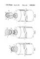
- FIG. 1is an isometric view of a container according to the invention with the replaceable cap in place;
- FIG. 2is a vertical view in enlarged scale, with some parts sectioned, of the upper portion of the container of FIG. 1;
- FIG. 3is an isometric view of the container of FIG. 1 with the replaceable cap removed illustrating how it can be inverted for engagement with a sealing member on the container;
- FIG. 4is a vertical view with parts sectioned illustating the engagement of the recess in the top of the removable cap with the sealing member on a modified form of the container;
- FIG. 5is an isometric view of the container of FIG. 1 with the sealing member removed and the cap in position for being replaced on the container as a resealing closure.
- a container 1includes a tubular body portion 3 topped by a shoulder portion 5 which terminates in a neck portion 7.
- the neck and shoulder portions in such containersare typically compression molded onto the body portion using a thermoplastic material.
- the lower, open end of the tubular, thermoplastic body portion 3forms a fill opening (not shown).
- the bottom of the containeris sealed by molding the thermoplastic material into a flat bottom 9, as shown in the containers of FIGS. 1, 3 and 5, or into a pinched bottom 11, as shown in FIG. 4.
- Such techniquesare conventional and form no part of the present invention other than that they provide a means of making the container of this invention and filling it other than through the container neck.
- the neck portion 7 of the container 1defines an outlet 13.
- the containeris formed with a seal member 15 integrally molded onto the end of the neck 7, and extending completely across and fully closing the outlet 13.
- the seal member 15is axially aligned with the neck and where they join is a separation line 17 formed by an external, undercut which makes the material thinner and therefore, weaker along this line.
- the neck portion 7tapers up as at 18 to this separation line 17 while the seal member 15 extends radially outward from this point.
- the seal member 15is formed with a bore 20 on its inner surface which is a continuation of the bore forming the outlet 13 in the neck portion 7.
- the integral seal member 15is generally circular with an irregular outer edge.
- the outer edgeis made irregular by axially extending serrations 19. These serrations 19 taper axially inward in a direction away from the body of the container at about a 5° angle.
- the neck 7is provided with external threads 21 for receiving a cap 23.
- the cap 23has a generally cylindrical skirt 25 in which are integrally molded internal threads 27 which engage the threads 21 on the neck 7.
- the end wall 29 of the capis provided with an external recess 31 centered on the axis of the cap.
- the side wall of this recess 31is provided with serrations 33 which match the serrations 19 on the seal member 15 and are similarly tapered at about 5° to facilitate their engagement.
- the outer surface of skirt portion 25 of the cap 23may be provided with scalloped, axially extending indentations 35 or other conventional surface treatment to provide a gripping surface for rotating the cap 23.
- the cap 23is unthreaded from the neck, turned over as illustrated in FIG. 3, and placed inverted on the top of the container with the serrations 33 engaging those 19 on the seal member 15, as shown in FIG. 4. Rotation of the cap 23 applies torque to the seal member 15 which tears it from the neck portion 7 along the separation line 17 thus opening the outlet 13.
- the contents of the container 1can then be selectively dispensed through the outlet 13.
- the cap 23can then be turned back over to the position shown in FIG. 2 and threaded onto the neck of the container to form a conventional replaceable closure for the outlet 13.
- a shoulder 22 on the capseats on a shoulder 24 on the neck portion 7 to form the reusable seal.
- thermoplastic containers with tear away sealstypically leave a ragged, rough edge to the opening formed by removal of the seal.
- solid particlesBy adding solid particles to the thermoplastic, it has been found that the thermoplastic material is made brittle enough that it breaks cleanly along a separation line formed by an undercut such as at 17 in the container described above.
- Many of the presently used thermoplastic squeezable containersare made of polyethylene.
- an antiblock material identified as Polyethylene Antiblock Masterbatch Code 10126 by its manufacturer, Ampacet Corporation, of Mount Vernon, N.Y.was used to supply the additive.
- the productcontains about 20% solid particulate material, believed to be a diatomaceous silica, mixed in a low density polyethylene base which is normally used to make polyethylene films in which the wraps of the film on a roll do not stick together because the particles are thick enough to prevent complete surface contact between adjacent wraps.
- This materialwas added to the polyethylene used to compression mold the container heads in varying amounts. Again, it was found that a resultant mixture with 3% to 16% of the solid particulate material by weight produced the desired results of a relatively clean break within the confines of the separation line 17 with the ideal amount being about 8%.
- nepheline syenitesold under the trademark MINEX by Indusmin Limited of Toronto, Canada. It is a naturally occurring igneous feldspathic rock which can be chemically identified as sodium potassium aluminum silicate with a chemical formula of:
- a diatomaceous earth or silica, or diatomitesold under the trademark DICALITE by the manufacturer, Grefco, Inc. of Torrance, Calif. which consists predominantely of silicon dioxide; a microcrystalline silicon dioxide sold under the trademark IMSIL by the manufacturer, Illinois Minerals Co. of Cario, Ill. which is over 99.5% silicon dioxide; and microcrystalline soft silica identified as 1A Rouge by its manufacturer, Tammsco, Inc. of Tamms, Ill. which is also over 99.5% silicon dioxide.
- 3% to 16% and preferably about 8% by weight of the particulate materialprovided the desired results.
- the Dicalitecomprised soft silica short polymer chain crystals which results in a more elastic structure and was not as transparent as the MINEX.
- the INSILworked well and the 1A Rouge flowed well, and had good torque break-off, but it discolored. All of the siliceous materials used had an average particle size of 10 microns or less.
- the addition of a fillerweakens the polymer matrix with inert particles and reduces the surface tension.
- the reduced surface tension and weakened filmprovide the proper tear properties for the twist-off to be functionally acceptable for large orifices.
- the orifices in the above exampleswere about 0.320 inches in diameter.
Landscapes
- Engineering & Computer Science (AREA)
- Mechanical Engineering (AREA)
- Closures For Containers (AREA)
Abstract
Description
3Na.sub.2 O.K.sub.2 O.4.5Al.sub.2 O.sub.3.2O SiO.sub.2
Claims (21)
Priority Applications (5)
| Application Number | Priority Date | Filing Date | Title |
|---|---|---|---|
| US06/768,847US4666063A (en) | 1985-08-23 | 1985-08-23 | Container with twist-off tamper evident feature |
| GB8620152AGB2179641B (en) | 1985-08-23 | 1986-08-19 | Improvements in or relating to a container |
| SE8603504ASE463413B (en) | 1985-08-23 | 1986-08-20 | A CONTAINER |
| CA000516654ACA1285523C (en) | 1985-08-23 | 1986-08-22 | Container with twist-off tamper evident feature |
| FR868612031AFR2586403B1 (en) | 1985-08-23 | 1986-08-25 | CONTAINER COMPRISING A DEVICE FOR OBTAINING ANY OPENING HANDLING |
Applications Claiming Priority (1)
| Application Number | Priority Date | Filing Date | Title |
|---|---|---|---|
| US06/768,847US4666063A (en) | 1985-08-23 | 1985-08-23 | Container with twist-off tamper evident feature |
Publications (1)
| Publication Number | Publication Date |
|---|---|
| US4666063Atrue US4666063A (en) | 1987-05-19 |
Family
ID=25083668
Family Applications (1)
| Application Number | Title | Priority Date | Filing Date |
|---|---|---|---|
| US06/768,847Expired - LifetimeUS4666063A (en) | 1985-08-23 | 1985-08-23 | Container with twist-off tamper evident feature |
Country Status (5)
| Country | Link |
|---|---|
| US (1) | US4666063A (en) |
| CA (1) | CA1285523C (en) |
| FR (1) | FR2586403B1 (en) |
| GB (1) | GB2179641B (en) |
| SE (1) | SE463413B (en) |
Cited By (31)
| Publication number | Priority date | Publication date | Assignee | Title |
|---|---|---|---|---|
| US4785963A (en)* | 1988-01-11 | 1988-11-22 | Rieke Corporation | Tamper-evident buttress plug closure |
| USD320162S (en) | 1989-01-25 | 1991-09-24 | Baumac International | Atomizer nozzle |
| US5203838A (en)* | 1990-08-14 | 1993-04-20 | Cebal | Assembly comprising an opening capsule and a receptacle with a tamperproof cover |
| US5586672A (en)* | 1992-06-19 | 1996-12-24 | Cebal, S.A. | Tube made of plastics material having a tearable cap, said tube with a cover |
| WO1997010155A1 (en)* | 1995-09-15 | 1997-03-20 | Egon Erlich | Tamper-evident container |
| EP0775498A3 (en)* | 1995-10-24 | 1997-09-10 | Bemis Mfg | Method and apparatus for removing and disposing of body fluids |
| US6244311B1 (en) | 1994-12-29 | 2001-06-12 | Bemis Manufacturing Company | Method and apparatus for removing and disposing of body fluids |
| EP1129956A1 (en)* | 2000-02-29 | 2001-09-05 | H. Obrist & Co. AG | Container closure arrangement |
| US6358232B1 (en) | 1994-12-29 | 2002-03-19 | Bemis Manufacturing Company | Method and apparatus for removing and disposing of body fluids |
| US6368310B1 (en) | 1993-06-08 | 2002-04-09 | Bemis Manufacturing Company | Medical suction system |
| US6544609B1 (en) | 2000-07-12 | 2003-04-08 | Alcoa Closure Systems International, Inc. | Stiff and impact resistant compositions containing poly(propylene) or poly(ethylene/propylene) and calcium carbonate for closures |
| US6626877B2 (en) | 2000-03-28 | 2003-09-30 | Bemis Manufacturing Company | Medical suction apparatus and methods for draining same |
| US6672477B2 (en) | 2001-01-12 | 2004-01-06 | Bemis Manufacturing Company | Method and apparatus for disposing of bodily fluids from a container |
| US20040143228A1 (en)* | 2000-03-28 | 2004-07-22 | Bemis Manufacturing Company | Medical suction apparatus and methods for draining same |
| US20040204693A1 (en)* | 2000-03-28 | 2004-10-14 | Bemis Manufacturing Company | Medical suction apparatus and draining of same |
| US20050101922A1 (en)* | 2003-11-07 | 2005-05-12 | Bemis Manufacturing Company | Suction canister and drainage of same |
| US20060151417A1 (en)* | 2002-11-13 | 2006-07-13 | Peter Fuchs | Tamper evident tube closure with twist-away centering |
| US20070045316A1 (en)* | 2005-08-30 | 2007-03-01 | Arnljots Anna-Maria S | Lid for beverage container |
| US20080121653A1 (en)* | 2005-05-30 | 2008-05-29 | Cebal Sas | Sealing Condition of Multiple-Container, in Particular Double-Tube, Packages Designed for Instant Preparation |
| US20100021089A1 (en)* | 2008-07-24 | 2010-01-28 | Arvizu Gilbert | Re-sealable spigot for a collapsible beverage container |
| US20100084436A1 (en)* | 2008-07-24 | 2010-04-08 | Sports Pouch Beverage Co., Inc. | Re-sealable spigot for a collapsible beverage container |
| US20110132941A1 (en)* | 2009-12-08 | 2011-06-09 | Kim Sang Soon | Spout for a pouch |
| US20110315720A1 (en)* | 2010-06-28 | 2011-12-29 | Unicep Packaging, Inc. | Dispenser with twist lock fitting |
| US8568634B2 (en) | 2010-08-04 | 2013-10-29 | Silgan Plastics Llc | Blow molding method and apparatus for forming squeezable plastic container |
| US20140217131A1 (en)* | 2011-09-09 | 2014-08-07 | Colgate-Palmolive Company | Containers with severable closures |
| CN104340499A (en)* | 2014-11-07 | 2015-02-11 | 上海三樱包装材料有限公司 | Hose sealing packaging structure |
| US20150165122A1 (en)* | 2012-08-08 | 2015-06-18 | Sanofi-Aventis Deutschland Gmbh | Drug delivery device with tamper-evident closure |
| US9120602B2 (en)* | 2012-10-11 | 2015-09-01 | Sonoco Development Incorporation | Stand-up caulk dispenser |
| US9126728B1 (en) | 2013-02-05 | 2015-09-08 | Stephen Elston | Child resistant cap and related apparauts and method |
| US11059633B2 (en) | 2019-10-31 | 2021-07-13 | Cheer Pack North America | Flip-top closure for container |
| US20230192367A1 (en)* | 2020-06-11 | 2023-06-22 | Bisio Progetti S.P.A. | Vial for fluid products with childproof system |
Families Citing this family (1)
| Publication number | Priority date | Publication date | Assignee | Title |
|---|---|---|---|---|
| GB0820850D0 (en) | 2008-11-14 | 2008-12-24 | Domino Printing Sciences Plc | Improvements in or relating to inkjet printing |
Citations (24)
| Publication number | Priority date | Publication date | Assignee | Title |
|---|---|---|---|---|
| US2849739A (en)* | 1952-11-04 | 1958-09-02 | A H Wirz Inc | Sealing nitrocellulose cement |
| US3156383A (en)* | 1962-04-05 | 1964-11-10 | Maison Ind Tecnico Chimiche Ne | Expansible single use dispensing container |
| US3162339A (en)* | 1961-11-29 | 1964-12-22 | Tuboplast France | Container with a breakable seal |
| CA731236A (en)* | 1966-03-29 | General Electric Company | Calcium carbonate filled polyethylene | |
| US3393815A (en)* | 1966-10-07 | 1968-07-23 | Frank J. Turecek | Child-proof pill bottle |
| GB1130234A (en)* | 1965-05-24 | 1968-10-09 | Jakob Niederer | Closure assemblies for a bottle or the like |
| US3409159A (en)* | 1966-08-01 | 1968-11-05 | Evert D. Velt | Stopper and cap combination |
| US3632004A (en)* | 1969-09-17 | 1972-01-04 | Shell Oil Co | Fused container closure and means facilitating removal of the same |
| GB1271887A (en)* | 1969-05-10 | 1972-04-26 | Gerhard Hansen | Improvements in or relating to containers |
| US3744654A (en)* | 1971-08-02 | 1973-07-10 | H Bromberg | Safety closure device |
| US3841513A (en)* | 1972-08-10 | 1974-10-15 | Connor I O | Container having safety closure |
| US3894985A (en)* | 1974-02-14 | 1975-07-15 | Johns Manville | Non-coloring diatomite-filled polyolefins |
| US3908654A (en)* | 1974-08-02 | 1975-09-30 | Rit Rech Ind Therapeut | Dispensing package for a dry biological and a liquid diluent |
| US3950917A (en)* | 1973-03-07 | 1976-04-20 | American Hospital Supply Corporation | Method of opening a double screw cap system for sterile medical container |
| US3993223A (en)* | 1974-07-25 | 1976-11-23 | American Home Products Corporation | Dispensing container |
| US4022749A (en)* | 1964-05-18 | 1977-05-10 | Entoleter, Inc. | Formation of composite particulate material using high energy rotary impact milling |
| US4056209A (en)* | 1977-03-23 | 1977-11-01 | W.P. Energy Technology Systems | Medication bottle having a safety cap |
| US4104289A (en)* | 1976-09-20 | 1978-08-01 | The Dow Chemical Company | Filled thermoplastic resin compositions |
| US4125514A (en)* | 1976-10-04 | 1978-11-14 | Tba Industrial Products Limited | Manufacture of moulding materials |
| US4157765A (en)* | 1977-10-28 | 1979-06-12 | Cebal | Inviolability device for container having its neck closed by a screw cap |
| GB1580305A (en)* | 1977-03-14 | 1980-12-03 | Baxter Travenol Lab | Airtight container |
| US4407986A (en)* | 1980-02-29 | 1983-10-04 | Idemitsu Petrochemical Co., Ltd. | Polypropylene composition |
| US4533602A (en)* | 1983-03-29 | 1985-08-06 | Ube Industries, Ltd. | Modified polyolefin composition useful for bonding materials |
| US4560712A (en)* | 1984-12-27 | 1985-12-24 | Mobil Oil Company | Polypropylene compositions containing bimodal calcium carbonate and a polysiloxane |
Family Cites Families (5)
| Publication number | Priority date | Publication date | Assignee | Title |
|---|---|---|---|---|
| FR1426663A (en)* | 1964-03-12 | 1966-01-28 | Unilever Nv | Container and closure device for said container |
| DE2849681A1 (en)* | 1978-11-16 | 1980-05-29 | Novoplast Verpackungen | MUG-LIKE PACKAGING JAR |
| US4176755A (en)* | 1979-01-26 | 1979-12-04 | Baxter Travenol Laboratories, Inc. | Resealable pour bottle with severing ring |
| FR2574053B3 (en)* | 1984-12-04 | 1987-06-05 | Barbe Maurice | PLASTIC CAP FOR BOTTLES WITH A THREAD WITH A SCREW |
| DE8504383U1 (en)* | 1985-02-16 | 1985-03-28 | Bayer Ag, 5090 Leverkusen | Tube-shaped container |
- 1985
- 1985-08-23USUS06/768,847patent/US4666063A/ennot_activeExpired - Lifetime
- 1986
- 1986-08-19GBGB8620152Apatent/GB2179641B/ennot_activeExpired
- 1986-08-20SESE8603504Apatent/SE463413B/ennot_activeIP Right Cessation
- 1986-08-22CACA000516654Apatent/CA1285523C/ennot_activeExpired - Fee Related
- 1986-08-25FRFR868612031Apatent/FR2586403B1/ennot_activeExpired
Patent Citations (24)
| Publication number | Priority date | Publication date | Assignee | Title |
|---|---|---|---|---|
| CA731236A (en)* | 1966-03-29 | General Electric Company | Calcium carbonate filled polyethylene | |
| US2849739A (en)* | 1952-11-04 | 1958-09-02 | A H Wirz Inc | Sealing nitrocellulose cement |
| US3162339A (en)* | 1961-11-29 | 1964-12-22 | Tuboplast France | Container with a breakable seal |
| US3156383A (en)* | 1962-04-05 | 1964-11-10 | Maison Ind Tecnico Chimiche Ne | Expansible single use dispensing container |
| US4022749A (en)* | 1964-05-18 | 1977-05-10 | Entoleter, Inc. | Formation of composite particulate material using high energy rotary impact milling |
| GB1130234A (en)* | 1965-05-24 | 1968-10-09 | Jakob Niederer | Closure assemblies for a bottle or the like |
| US3409159A (en)* | 1966-08-01 | 1968-11-05 | Evert D. Velt | Stopper and cap combination |
| US3393815A (en)* | 1966-10-07 | 1968-07-23 | Frank J. Turecek | Child-proof pill bottle |
| GB1271887A (en)* | 1969-05-10 | 1972-04-26 | Gerhard Hansen | Improvements in or relating to containers |
| US3632004A (en)* | 1969-09-17 | 1972-01-04 | Shell Oil Co | Fused container closure and means facilitating removal of the same |
| US3744654A (en)* | 1971-08-02 | 1973-07-10 | H Bromberg | Safety closure device |
| US3841513A (en)* | 1972-08-10 | 1974-10-15 | Connor I O | Container having safety closure |
| US3950917A (en)* | 1973-03-07 | 1976-04-20 | American Hospital Supply Corporation | Method of opening a double screw cap system for sterile medical container |
| US3894985A (en)* | 1974-02-14 | 1975-07-15 | Johns Manville | Non-coloring diatomite-filled polyolefins |
| US3993223A (en)* | 1974-07-25 | 1976-11-23 | American Home Products Corporation | Dispensing container |
| US3908654A (en)* | 1974-08-02 | 1975-09-30 | Rit Rech Ind Therapeut | Dispensing package for a dry biological and a liquid diluent |
| US4104289A (en)* | 1976-09-20 | 1978-08-01 | The Dow Chemical Company | Filled thermoplastic resin compositions |
| US4125514A (en)* | 1976-10-04 | 1978-11-14 | Tba Industrial Products Limited | Manufacture of moulding materials |
| GB1580305A (en)* | 1977-03-14 | 1980-12-03 | Baxter Travenol Lab | Airtight container |
| US4056209A (en)* | 1977-03-23 | 1977-11-01 | W.P. Energy Technology Systems | Medication bottle having a safety cap |
| US4157765A (en)* | 1977-10-28 | 1979-06-12 | Cebal | Inviolability device for container having its neck closed by a screw cap |
| US4407986A (en)* | 1980-02-29 | 1983-10-04 | Idemitsu Petrochemical Co., Ltd. | Polypropylene composition |
| US4533602A (en)* | 1983-03-29 | 1985-08-06 | Ube Industries, Ltd. | Modified polyolefin composition useful for bonding materials |
| US4560712A (en)* | 1984-12-27 | 1985-12-24 | Mobil Oil Company | Polypropylene compositions containing bimodal calcium carbonate and a polysiloxane |
Cited By (49)
| Publication number | Priority date | Publication date | Assignee | Title |
|---|---|---|---|---|
| US4785963A (en)* | 1988-01-11 | 1988-11-22 | Rieke Corporation | Tamper-evident buttress plug closure |
| USD320162S (en) | 1989-01-25 | 1991-09-24 | Baumac International | Atomizer nozzle |
| US5203838A (en)* | 1990-08-14 | 1993-04-20 | Cebal | Assembly comprising an opening capsule and a receptacle with a tamperproof cover |
| US5586672A (en)* | 1992-06-19 | 1996-12-24 | Cebal, S.A. | Tube made of plastics material having a tearable cap, said tube with a cover |
| US6673055B2 (en) | 1993-06-08 | 2004-01-06 | Bemis Manufacturing Company | Medical suction system |
| US7115115B2 (en) | 1993-06-08 | 2006-10-03 | Bemis Manufacturing Company | Medical suction system |
| US6368310B1 (en) | 1993-06-08 | 2002-04-09 | Bemis Manufacturing Company | Medical suction system |
| US6244311B1 (en) | 1994-12-29 | 2001-06-12 | Bemis Manufacturing Company | Method and apparatus for removing and disposing of body fluids |
| US6358232B1 (en) | 1994-12-29 | 2002-03-19 | Bemis Manufacturing Company | Method and apparatus for removing and disposing of body fluids |
| US6494869B1 (en) | 1994-12-29 | 2002-12-17 | Bemis Manufacturing Company | Method and apparatus for removing and disposing of body fluids |
| WO1997010155A1 (en)* | 1995-09-15 | 1997-03-20 | Egon Erlich | Tamper-evident container |
| EP0775498A3 (en)* | 1995-10-24 | 1997-09-10 | Bemis Mfg | Method and apparatus for removing and disposing of body fluids |
| WO2001064537A1 (en)* | 2000-02-29 | 2001-09-07 | H. Obrist & Co. Ag | Container closure assembly |
| EP1129956A1 (en)* | 2000-02-29 | 2001-09-05 | H. Obrist & Co. AG | Container closure arrangement |
| US6626877B2 (en) | 2000-03-28 | 2003-09-30 | Bemis Manufacturing Company | Medical suction apparatus and methods for draining same |
| US7674248B2 (en) | 2000-03-28 | 2010-03-09 | Bemis Manufacturing Company | Medical suction apparatus and methods for draining same |
| US20040059303A1 (en)* | 2000-03-28 | 2004-03-25 | Bemis Manufacturing Company | Medical suction apparatus and methods for draining same |
| US20040143228A1 (en)* | 2000-03-28 | 2004-07-22 | Bemis Manufacturing Company | Medical suction apparatus and methods for draining same |
| US20040204693A1 (en)* | 2000-03-28 | 2004-10-14 | Bemis Manufacturing Company | Medical suction apparatus and draining of same |
| US7585292B2 (en) | 2000-03-28 | 2009-09-08 | Bemis Manufacturing Company | Medical suction apparatus and draining of same |
| US6544609B1 (en) | 2000-07-12 | 2003-04-08 | Alcoa Closure Systems International, Inc. | Stiff and impact resistant compositions containing poly(propylene) or poly(ethylene/propylene) and calcium carbonate for closures |
| US6672477B2 (en) | 2001-01-12 | 2004-01-06 | Bemis Manufacturing Company | Method and apparatus for disposing of bodily fluids from a container |
| US7614514B2 (en)* | 2002-11-13 | 2009-11-10 | Hoffmann Neopac Ag | Tamper evident tube closure with twist-away centering |
| US20060151417A1 (en)* | 2002-11-13 | 2006-07-13 | Peter Fuchs | Tamper evident tube closure with twist-away centering |
| US20050101922A1 (en)* | 2003-11-07 | 2005-05-12 | Bemis Manufacturing Company | Suction canister and drainage of same |
| US8622245B2 (en)* | 2005-05-30 | 2014-01-07 | Cebal S.A.S. | Sealing condition of multiple-container, in particular double-tube, packages designed for instant preparation |
| US20080121653A1 (en)* | 2005-05-30 | 2008-05-29 | Cebal Sas | Sealing Condition of Multiple-Container, in Particular Double-Tube, Packages Designed for Instant Preparation |
| US20070045316A1 (en)* | 2005-08-30 | 2007-03-01 | Arnljots Anna-Maria S | Lid for beverage container |
| US20100021089A1 (en)* | 2008-07-24 | 2010-01-28 | Arvizu Gilbert | Re-sealable spigot for a collapsible beverage container |
| US20100084436A1 (en)* | 2008-07-24 | 2010-04-08 | Sports Pouch Beverage Co., Inc. | Re-sealable spigot for a collapsible beverage container |
| US8459512B2 (en)* | 2008-07-24 | 2013-06-11 | Sports Pouch Beverage Co., Inc. | Re-sealable spigot for a collapsible beverage container |
| US8474665B2 (en)* | 2008-07-24 | 2013-07-02 | Sports Pouch Beverage Co., Inc. | Re-sealable spigot for a collapsible beverage container |
| US20110132941A1 (en)* | 2009-12-08 | 2011-06-09 | Kim Sang Soon | Spout for a pouch |
| US20110315720A1 (en)* | 2010-06-28 | 2011-12-29 | Unicep Packaging, Inc. | Dispenser with twist lock fitting |
| US10293538B2 (en) | 2010-08-04 | 2019-05-21 | Silgan Plastics Llc | Blow molding method and apparatus for forming squeezable plastic container |
| US11065802B2 (en) | 2010-08-04 | 2021-07-20 | Silgan Plastics Llc | Blow molding method and apparatus for forming squeezable plastic container |
| US11697241B2 (en) | 2010-08-04 | 2023-07-11 | Silgan Plastics Llc | Blow molding method and apparatus for forming squeezable plastic container |
| US8568634B2 (en) | 2010-08-04 | 2013-10-29 | Silgan Plastics Llc | Blow molding method and apparatus for forming squeezable plastic container |
| US9314956B2 (en) | 2010-08-04 | 2016-04-19 | Silgan Plastics Llc | Blow molding method and apparatus for forming squeezable plastic container |
| US20140217131A1 (en)* | 2011-09-09 | 2014-08-07 | Colgate-Palmolive Company | Containers with severable closures |
| JP2015524327A (en)* | 2012-08-08 | 2015-08-24 | サノフィ−アベンティス・ドイチュラント・ゲゼルシャフト・ミット・ベシュレンクテル・ハフツング | Drug delivery device with tamper evident closure |
| US20150165122A1 (en)* | 2012-08-08 | 2015-06-18 | Sanofi-Aventis Deutschland Gmbh | Drug delivery device with tamper-evident closure |
| US11123490B2 (en) | 2012-08-08 | 2021-09-21 | Sanofi-Aventis Deutschland Gmbh | Drug delivery device with tamper-evident closure |
| US9120602B2 (en)* | 2012-10-11 | 2015-09-01 | Sonoco Development Incorporation | Stand-up caulk dispenser |
| US9126728B1 (en) | 2013-02-05 | 2015-09-08 | Stephen Elston | Child resistant cap and related apparauts and method |
| CN104340499A (en)* | 2014-11-07 | 2015-02-11 | 上海三樱包装材料有限公司 | Hose sealing packaging structure |
| US11059633B2 (en) | 2019-10-31 | 2021-07-13 | Cheer Pack North America | Flip-top closure for container |
| US20230192367A1 (en)* | 2020-06-11 | 2023-06-22 | Bisio Progetti S.P.A. | Vial for fluid products with childproof system |
| US12172807B2 (en)* | 2020-06-11 | 2024-12-24 | Bisio Progetti S.P.A. | Vial for fluid products with childproof system |
Also Published As
| Publication number | Publication date |
|---|---|
| CA1285523C (en) | 1991-07-02 |
| FR2586403B1 (en) | 1989-07-13 |
| FR2586403A1 (en) | 1987-02-27 |
| GB2179641B (en) | 1989-08-09 |
| GB2179641A (en) | 1987-03-11 |
| SE463413B (en) | 1990-11-19 |
| SE8603504D0 (en) | 1986-08-20 |
| SE8603504L (en) | 1987-02-24 |
| GB8620152D0 (en) | 1986-10-01 |
Similar Documents
| Publication | Publication Date | Title |
|---|---|---|
| US4666063A (en) | Container with twist-off tamper evident feature | |
| CA1305100C (en) | Tamper-evident buttress plug closure | |
| CN100564236C (en) | Twist-off cap with inclined frangible membrane | |
| US4844250A (en) | Tamper-evident container assembly | |
| USRE39867E1 (en) | Tamper-evident container closure | |
| US4401227A (en) | Tamper indicating closure cap | |
| US4756438A (en) | Container with threaded closure and tamper-evident feature | |
| JPS6362431B2 (en) | ||
| US4382521A (en) | Vented closure | |
| CN100396573C (en) | Tamper-resistant caps with locking straps | |
| US4485934A (en) | Tamperproof closure | |
| US2153426A (en) | Sealed package and parts thereof | |
| JPS63232156A (en) | Safety packaging vessel consisting of sealing body and vessel | |
| US20050269373A1 (en) | Cover for dispensing closure with pressure actuated valve | |
| JPH0464941B2 (en) | ||
| WO2006066356A1 (en) | Tamper-evident closure and bead on container neck | |
| KR20010034041A (en) | Tamper evident closure for beverage | |
| US4570810A (en) | Cap with tamper indicating band | |
| JP2008517843A (en) | Snap top closing device | |
| US4771923A (en) | Tamper evidencing cap | |
| US4724972A (en) | Tamper evident container | |
| USRE40003E1 (en) | Tamper-evident container closure | |
| AU2004224056A1 (en) | Closure for a container | |
| GB2594721A (en) | Tamper evident and child resistant closure | |
| JPH0912054A (en) | False unsealing-preventing hinged cap |
Legal Events
| Date | Code | Title | Description |
|---|---|---|---|
| AS | Assignment | Owner name:WHEELING STAMPING COMPANY, 8TH STREET & HAZLETT AV Free format text:ASSIGNMENT OF ASSIGNORS INTEREST.;ASSIGNORS:HOLOUBEK, GEORGE H.;ANTHONY, EUGENE M.;HANS, ALLAN B.;REEL/FRAME:004450/0162 Effective date:19850819 | |
| STCF | Information on status: patent grant | Free format text:PATENTED CASE | |
| AS | Assignment | Owner name:MARYLAND NATIONAL BANK, SUITE 101, 2328 WEST JOPPA Free format text:SECURITY INTEREST;ASSIGNOR:WHEELING STAMPING COMPANY;REEL/FRAME:004918/0897 Effective date:19880713 | |
| FPAY | Fee payment | Year of fee payment:4 | |
| SULP | Surcharge for late payment | ||
| AS | Assignment | Owner name:COURTAULDS PACKAGING INC. Free format text:CHANGE OF NAME;ASSIGNOR:WHEELING STAMPING COMPANY;REEL/FRAME:005539/0918 Effective date:19900430 | |
| FPAY | Fee payment | Year of fee payment:8 | |
| FPAY | Fee payment | Year of fee payment:12 | |
| AS | Assignment | Owner name:THATCHER TUBES LLC, ILLINOIS Free format text:ASSIGNMENT OF ASSIGNORS INTEREST;ASSIGNOR:COURTAULDS PACKAGING INC.;REEL/FRAME:013678/0758 Effective date:20030117 | |
| AS | Assignment | Owner name:SILGAN TUBES CORPORATION, MISSOURI Free format text:ASSIGNMENT OF ASSIGNORS INTEREST;ASSIGNOR:THATCHER TUBES LLC;REEL/FRAME:013798/0072 Effective date:20030115 | |
| AS | Assignment | Owner name:DEUTSCHE BANK TRUST COMPANY AMERICA, NEW YORK Free format text:SECURITY INTEREST;ASSIGNOR:SLIGAN TUBES CORPORATION;REEL/FRAME:014108/0400 Effective date:20030115 | |
| AS | Assignment | Owner name:SILGAN PLASTICS CORPORATION (F/K/A SILGAN TUBES CO Free format text:RELEASE BY SECURED PARTY;ASSIGNOR:DEUTSCHE BANK TRUST COMPANY AMERICAS, AS COLLATERAL AGENT;REEL/FRAME:036814/0461 Effective date:20151015 |