US4665748A - Automatic continuous nulling of angular rate sensor - Google Patents
Automatic continuous nulling of angular rate sensorDownload PDFInfo
- Publication number
- US4665748A US4665748AUS06/789,655US78965585AUS4665748AUS 4665748 AUS4665748 AUS 4665748AUS 78965585 AUS78965585 AUS 78965585AUS 4665748 AUS4665748 AUS 4665748A
- Authority
- US
- United States
- Prior art keywords
- signal
- axis
- accelerometers
- coriolis
- drive
- Prior art date
- Legal status (The legal status is an assumption and is not a legal conclusion. Google has not performed a legal analysis and makes no representation as to the accuracy of the status listed.)
- Expired - Lifetime
Links
- 230000001133accelerationEffects0.000claimsabstractdescription47
- 230000000737periodic effectEffects0.000claimsabstractdescription8
- 238000001514detection methodMethods0.000claimsabstractdescription6
- 230000007246mechanismEffects0.000claimsdescription9
- 238000005070samplingMethods0.000claimsdescription2
- 238000000034methodMethods0.000description10
- 230000008859changeEffects0.000description9
- 230000001360synchronised effectEffects0.000description9
- 230000010354integrationEffects0.000description8
- 230000010363phase shiftEffects0.000description8
- 238000010586diagramMethods0.000description3
- 230000004044responseEffects0.000description3
- 230000035939shockEffects0.000description2
- 230000008901benefitEffects0.000description1
- 230000003111delayed effectEffects0.000description1
- 230000000694effectsEffects0.000description1
- 230000008569processEffects0.000description1
Images

Classifications
- G—PHYSICS
- G01—MEASURING; TESTING
- G01C—MEASURING DISTANCES, LEVELS OR BEARINGS; SURVEYING; NAVIGATION; GYROSCOPIC INSTRUMENTS; PHOTOGRAMMETRY OR VIDEOGRAMMETRY
- G01C19/00—Gyroscopes; Turn-sensitive devices using vibrating masses; Turn-sensitive devices without moving masses; Measuring angular rate using gyroscopic effects
- G01C19/56—Turn-sensitive devices using vibrating masses, e.g. vibratory angular rate sensors based on Coriolis forces
- G01C19/5719—Turn-sensitive devices using vibrating masses, e.g. vibratory angular rate sensors based on Coriolis forces using planar vibrating masses driven in a translation vibration along an axis
- G01C19/5733—Structural details or topology
- G01C19/574—Structural details or topology the devices having two sensing masses in anti-phase motion
- G—PHYSICS
- G01—MEASURING; TESTING
- G01C—MEASURING DISTANCES, LEVELS OR BEARINGS; SURVEYING; NAVIGATION; GYROSCOPIC INSTRUMENTS; PHOTOGRAMMETRY OR VIDEOGRAMMETRY
- G01C19/00—Gyroscopes; Turn-sensitive devices using vibrating masses; Turn-sensitive devices without moving masses; Measuring angular rate using gyroscopic effects
- G01C19/56—Turn-sensitive devices using vibrating masses, e.g. vibratory angular rate sensors based on Coriolis forces
- G01C19/5776—Signal processing not specific to any of the devices covered by groups G01C19/5607 - G01C19/5719
Definitions
- the present inventionrelates to an apparatus for determining angular rate of rotation utilizing accelerometers.
- Angular rate of rotation about a given coordinate axismay be measured by moving (e.g., vibrating) an accelerometer along an axis normal to the accelerometer's sensitive axis and normal to the rate axis about which rotation is to be measured.
- movinge.g., vibrating
- an accelerometeralong an axis normal to the accelerometer's sensitive axis and normal to the rate axis about which rotation is to be measured.
- the angular rotation vector of the bodyincludes a component along the X axis, then periodic motion of the accelerometer along the Y axis will result in a periodic Coriolis acceleration acting in the Z direction that will be sensed by the accelerometer.
- one preferred embodiment of a rotation rate sensorcomprises, for each axis, two accelerometers oriented with their sensitive axes parallel or antiparallel to one another and means for vibrating the accelerometers along an axis normal to their sensitive axes.
- a suitable method for vibrating such accelerometer pairsis described in U.S. Pat. No. 4,510,802.
- a parallelogram structureis used to vibrate the accelerometers along a common vibration axis.
- angular misalignment of the two accelerometers with respect to the desired sensitive axisinteracts with any phase shift that may exist between the vibration drive signal and the actual vibratory motion to produce a rate bias given by:
- ⁇is the vibration frequency
- ⁇ 1 and ⁇ 2are the misalignments of the first and second accelerometers respectively
- ⁇is the phase shift.
- the referenced applicationdescribes a process, using the characteristics of a parallelogram linkage, to set ( ⁇ 1 + ⁇ 2 ) and ⁇ essentially to zero.
- ⁇is the phase shift and misalignment angles be stable to the order of 15 microradians each.
- phase shift at the vibration frequencymay be a few degrees, and where stability better than a few hundred microradians cannot be guaranteed, alignment stability becomes extremely critical, and an improved technique is desirable for minimizing the rate bias set forth in Equation (1) above.
- the present inventionprovides an angular rate sensor that comprises a pair of accelerometers and that includes means for continuously nulling error signals resulting from misalignment of the accelerometers.
- the rate sensor of the present inventioncomprises first and second accelerometers.
- the first accelerometerhas a first force sensing axis and produces a first output signal indicating acceleration along the first force sensing axis.
- the second accelerometerhas a second force sensing axis and produces a second output signal indicating acceleration along the second force sensing axis.
- Mounting meansare provided for mounting the accelerometers such that their force sensing axes are both parallel to a common sensing axis, and such that the acceleromteres can be moved along a vibration axis normal to the sensing axis.
- a signal generatorproduces a periodic drive signal having a predetermined frequency
- drive means connected to the mounting meansis responsive to the drive signal for vibrating the first and second accelermeters along the vibration axis at said predetermined frequency.
- Signal processing meansreceives the first and second output signals and generates a Coriolis signal representing the Coriolis acceleration along the sensing axis resulting from movement of the accelerometers along the vibration axis and rotation of the body about a rate axis normal to the vibration axis and to the sensing axis.
- the only component of the Coriolis signalwould be that due to the Coriolis acceleration, which component is in phase with the vibration velocity and therefore in quadrature phase with respect to the drive signal.
- Components of the Coriolis signal that are in phase with the drive signalrepresent errors due to misalignment or angular accelerations.
- the signal processing meansincludes detection means that receives the Coriolis signal and produces a feedback signal that is a function of those "error" components of the Coriolis signal that are in phase with respect to the drive signal.
- the drive meansincludes means for combining the feedback signal with the drive signal, such that the in phase components are driven toward a null value.
- the detection meanspreferably comprises means for producing an analog signal having a magnitude corresponding to the amplitude of the components of the Coriolis signal that are in phase with respect to the drive signal, and means for integrating the analog signal to produce the feedback signal.
- the mounting meanspreferably comprises a parallelogram mechanism.
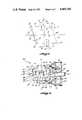
- FIG. 1is a diagram providing a conceptual illustration of a parallelogram assembly for vibrating two accelerometers along a vibration axis;
- FIG. 2is a side elevational view of a mechanism for implementing the parallelogram assembly illustrated in FIG. 1;
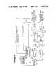
- FIG. 3is a block diagram of a system according to the present invention for determining angular rate using analog accelerometers
- FIG. 4is a block diagram of a system according to the present invention for determining angular rate using frequency output accelerometers.
- FIG. 1schematically illustrates a parallelogram arrangement for vibrating accelerometers 10 and 12 along the Y axis.
- the accelerometershave their sensitive axes substantially parallel to the Z axis and antiparallel to one another, the sensitive axis of accelerometer 10 being directed in a positive direction along the Z axis and the sensitive axis of accelerometer 12 being directed in a negative direction along the Z axis.
- Accelerometers 10 and 12are secured to accelerometer support members 14 and 16, respectively, that in turn are connected to a pair of linkage members 18 and 20 by pivots 22-25.
- Linkage members 18 and 20are mounted at central pivots 26 and 28, respectively.
- Support members 14 and 16are both parallel to the Y axis.
- accelerometers 10 and 12When linkage members 18 and 20 are vibrated about central pivots 26 and 28, respectively, through angles ⁇ , accelerometers 10 and 12 will vibrate along the Y axis with an amplitude of approximately ⁇ R ⁇ , where R represents the length of the linkage arm 18 or 20 from one of the central pivots 26 or 28 to one of pivots 22-25.
- the angle ⁇represents an initial offset (with respect to the Z axis) about which such vibration occurs
- the angles ⁇ 1 and ⁇ 2represent the angular misalignment of the sensitive axes of accelerometers 10 and 12 respectively with respect to the Z axis.
- Equation (2) and (3)represent back-and-forth movement of each accelerometer along a "vibration axis" that is inclined at an angle ⁇ with respect to the Y axis.
- the second term in Equation (2)represents a twice frequency acceleration resulting from the fact that the movement of each accelerometer is circular rather than truly linear.
- the motion of accelerometers 10 and 12is therefore essentially linear along the Y axis for small angles of ⁇ and ⁇ .
- the angular amplitude ⁇preferably has a value of 0.01-0.1 radians, and ⁇ preferably has a value of less than 0.01 radians.
- Suitable values for the frequency ⁇are in the range of 200-1000 radians/second. Further significance of the input axis motion described in Equations (2) and (3) will be discussed below in connection with FIGS. 3 and 4.
- FIG. 2illustrates one preferred embodiment of an accelerometer assembly 30 that includes accelerometers 10 and 12 mounted in the parallelogram arrangement indicated in FIG. 1.
- Accelerometers 10 and 12are secured to the accelerometer support members 14 and 16, and the accelerometer support members are in turn secured to linkage members 18 and 20 by flexure hinges 22-25.
- Linkage members 18 and 20are in turn secured to fixed supports 34 and 36 by flexure hinges 26 and 28, respectively, flexure hinges 22-25, 26 and 28 corresponding to pivots 22-25, 26 and 28 respectively of FIG. 1. Vibration of the accelerometers along the Y axis is effected by solenoids 40 and 42.
- the solenoidsare secured to fixed support 36 by bolts 44 and by brackets 46 and 48.
- Solenoid 40is coupled to support member 14 and solenoid 42 is coupled to support member 16.
- the solenoidsare driven 180° out of phase with one another, to cause back-and-forth motion of the accelerometers along the Y axis. Excessive vibrational movement of the apparatus is prevented by shock stops 50-53 between the support members and linkage members, and by shock stops 54-57 between fixed supports 34 and 36 and linkage members 18 and 20.
- the vibrational position of the parallelogram assemblyis measured by LVDT 60 mounted between bracket 62 secured to support member 14 and bracket 64 secured to support member 16.
- solenoids 40 and 42may be used to vibrate accelerometer assembly 30 along the Y axis.
- the drive meanscould comprise an electromagnetic voice coil mechanism connected to linkage members 18 and 20, or a D'Arsonval torque coil attached between support 36 and linkage member 20.
- the drive meanscould also comprise piezoelectric bender elements.
- the position sensing meansis not required to have a DC response, and LVDT 60 could therefore be replaced with an electromagnetic velocity coil mechanism or with other conventional position or motion sensing means.
- a number of suitable, alternate drive and position or velocity sensing techniquesare described in U.S. Pat. No. 4,510,802 and in the U.S. Pat. No. 4,590,801.
- the vibrational movement of accelerometers 10 and 12 along the Y axisinteracts with rotational movement of the body in which the accelerometers are mounted about the X axis (perpendicular to the plane of FIGS. 1 and 2), to produce a Coriolis acceleration directed along the Z axis.
- the output of accelerometers 10 and 12will therefore include a component representing linear acceleration along the Z axis, as well as a second component representing a Coriolis acceleration due to vibration along the Y axis and rotation about the X axis.
- a signal processor for separating the linear acceleration signal from the angular rate signal in the output signals of accelerometers 10 and 12is illustrated in FIG. 3.
- control pulse generator 70generates signals on lines 72 and 74 that represent the functions SGN sin ⁇ t and SGN cos ⁇ t, respectively.
- the symbol SGNrepresents "sign of".
- the signal on line 72may comprise a series of pulses occurring at phase value 0, ⁇ , 2 ⁇ , etc. of sin ⁇ t
- the signal on line 74may comprise a similar pulse train at phase values of ⁇ /2, 3 ⁇ /2, etc. of the same function.
- the signal representing SGN sin ⁇ tis input to sine wave generator 76, and the sine wave generator produces a signal proportional to sin ⁇ t on line 78.
- the signal on line 78is input to a servo system that causes the accelerometers to vibrate along the Y axis at frequency ⁇ .
- the servo systemcomprises summing junction 80, solenoid drive 82 and demodulator 84.
- the sin ⁇ t signal on line 78is input to summing junction 80, and the output of the summing junction on line 86 is input to solenoid drive 82 that includes a high gain amplifier.
- solenoid drive 82is used to drive the solenoids of accelerometer assembly 30 to produce a vibratory motion of the accelerometers along the Y axis.
- the motion of the accelerometersis sensed by LVDT 60, and the output of the LVDT is demodulated by demodulator 84 to produce feedback signal that is input to summing junction 80 via line 88.
- Summing junction 80receives the feedback signal and further receives an alignment signal on line 90 from alignment channel 92, and combines such signals with the signal on line 78 with the polarities indicated in FIG. 3.
- the function of the alignment signalis described below.
- the gain provided by solenoid drive 82can be made very high, such that the vibratory motion of accelerometers 10 and 12 closely tracks the signal sin ⁇ t on line 78.
- Accelerometers 10 and 12produce output signals a 1 and a 2 respectively, and the output signals are transmitted over lines 100 and 102 respectively to preseparation processor 104. Operation of the system is most easily understood by looking first at the ideal case in which the accelerometers and their associated circuitry have no errors due to scaling, phase shift, or misalignment, so that a 1 and a 2 may be considered as either inputs (accelerations sensed) or outputs, and in which input rate ⁇ x is constant so that there are no angular acceleration terms.
- Preseparation processor 104 shown in FIG. 3is appropriate for a paired accelerometer arrangement of the type shown in FIG. 1 where the force sensing axes are antiparallel to one another.
- the total accelerations sensed by the accelerometersare given by:
- Equations (4) and (5)have opposite signs due to the opposite directions of the sensitive axes of accelerometers 10 and 12.
- the Coriolis terms in Equations (4) and (5)have the same signs because both the sensitive axes and the vibrational velocity of the accelerometers are opposite to one another, thereby producing Coriolis accelerations that act in the same direction relative to the respective sensitive axes.
- Preseparation processor 104comprises summing junctions 106 and 108.
- Summing junction 106adds the a 1 and a 2 signals, and summing junction 108 subtracts the a 1 and a 2 signals.
- the linear acceleration componentsare eliminated by summing junction 106, and the result is a Coriolis signal on line 110 proportional to rotation rate ⁇ x .
- This Coriolis signal on line 110is input to scaling amplifier 114, and the resulting scaled Coriolis signal on line 118 is input to angular rate channel 120 and to alignment channel 92.
- the Coriolis componentsare eliminated by summing junction 108, and the result is a linear acceleration signal proportional to A z on line 112.
- the linear acceleration signalis input to scaling amplifier 116, and the resulting scaled linear acceleration signal on line 122 is input to linear acceleration channel 124. It will be appreciated that if the sensitive axes of accelerometers 10 and 12 were parallel rather than antiparallel, that summing junction 106 would subtract the a 1 and a 2 signals and summing junction 108 would add the a 1 and a 2 signals.
- Angular rate channel 120, alignment channel 92 and linear acceleration channel 124each comprises at least one integration circuit and a sample and hold circuit. Both the angular rate channel and the alignment channel receive the scaled Coriolis signal on line 118 as an input signal, and the linear acceleration channel receives the scaled linear acceleration signal on line 122 as an input signal.
- each channelintegrates its input signal over one full cycle of the vibration period 2 ⁇ / ⁇ , and stores the result of such integration in its sample and hold circuit.
- the rate channelincludes two integrators that are alternately used to perform the required integrations, so that the commencement of an integration is not delayed by the time required to store the result of the preceding integration, and reset the integrator.
- the alignment channelrequires only one integrator, since it need not be reset at each cycle.
- Linear acceleration channel 124integrates its input signal directly, to produce an output signal A z on line 132.
- the alignment channel and the angular rate channeleach modulate their respective input signals prior to integration.
- the modulation performed by the alignment channelis described below.
- the modulationis based upon the SGN cos ⁇ t function represented by the signal provided on line 74 by control signal generator 70.
- the effect of modulating by SGN cos ⁇ t and integrating over the period 2 ⁇ / ⁇is that signals synchronous (i.e., in phase) with cos ⁇ t are rectified, while DC signals and signals synchronous with sin ⁇ t cancel.
- the angular rate channeltherefore rectifies the Coriolis components of Equations (4) and (5), to produce an output signal on line 130 proportional to ⁇ x . Furthermore, it may readily be shown that modulation by the function SGN cos ⁇ t followed by integration cancels components in phase with cos 2 ⁇ t. As a result, both terms of Equation (3) are eliminated, and output signal ⁇ x on line 130 is unaffected by the parallelogram vibration arrangement.
- the backand-forth vibration of the accelerometerwill include an acceleration proportional to sin ⁇ 1 sin ⁇ t that is directed along the accelerometer's sensitive axis.
- This accelerationresults in a misalignment component, also synchronous with sin ⁇ t, in the accelerometer's output signal a 1 .
- the misalignment componentis synchronous with sin ⁇ t, it will be canceled in angular rate channel 120 and will not affect the angular rate output ⁇ x .
- Alignment channel 92receives as input the scaled Coriolis signal on line 118, modulates such signal by the function SGN sin ⁇ t, and then integrates the modulated signal over each full cycle of the vibration period 2 ⁇ / ⁇ .
- the resulting feedback signal on line 90is input to summing junction 80, where it is combined as indicated with the drive signal sin ⁇ t and with the feedback signal on line 88 to produce a net drive or error signal on line 86.
- Modulation by SGN sin ⁇ t, followed by integration without resetcauses the components proportional to cos ⁇ t to cancel, and provides a feedback signal that is proportional only to the integral of the components of the scaled Coriolis signal that are synchronous with sin ⁇ t.
- the combination of signals at summing junction 80results in a feedback signal on line 88 having a DC component that tracks the DC or slowly varying feedback signal on line 90, thereby continuously driving the Coriolis components synchronous with sin ⁇ t to a null value.
- the components that are nulledinclude not only the mislignment component described above, but also other error signals as well as signal caused by angular accelerations.
- a further benefit of alignment channel 92is that it provides an optimal DC signal for loop closure of the vibration servo system. As a result, the feedback elements exemplified by LVDT 60 and demodulator 84 are no longer required to have a DC response, and AC elements can be used.
- FIG. 3illustrates the application of the present invention to a system in which accelerometers 10 and 12 produce analog output signals.
- FIG. 4illustrates a corresponding system in which accelerometers 10 and 12 are frequency output accelerometers, i.e., accelerometers such as vibrating beam accelerometers in which the frequency of each output signal is a function of the sensed acceleration.
- the embodiment of FIG. 4includes summing juction 140, solenoid drive 142 and demodulator 144 that may be identical to the corresponding elements of the analog embodiments shown in FIG. 3.
- the drive signal sin ⁇ tis derived from clock 156 through divide by N circuit 170 and phase lock loop 172.
- Divide by N circuit 170divides the high frequency signal produced by clock 156 to produce a signal on line 174 having a frequency ⁇ on the order of 100 Hz.
- the low frequency signal on line 174is input to phase lock loop 172, and the phase lock loop converts such signal to a sinusoidal signal sin ⁇ t of the same frequency on line 176.
- the sinusoidal signal on line 176is input to summing junction 140, and operates in a manner identical to the drive signal provided to summing junction 80 on line 78 of the embodiment of FIG. 3.
- Accelerometers 10 and 12produce output signals a 1 and a 2 , on lines 150 and 152 respectively, that have frequencies corresponding to the accelerations sensed by the respective accelerometers.
- the output signals on lines 150 and 152are input to counting circuit 154.
- Also input to counting circuit 154is a high frequency clock signal on line 158 generated by clock 156.
- Counting circuit 154counts the cycles of the a 1 and a 2 signals and the clock signal on line 158.
- Microprocessor 160inputs such counts via bus 162, and performs appropriate calculations to determine angular rate ⁇ x and linear acceleration A Z .
- ⁇is the difference between the phase changes of the accelerometer output signals over time T
- ⁇is the sum of the phase changes of the output signals over time interval T
- A, F, and Bare constants.
- the angular change ⁇ x over a vibration periodmay be determined by first demodulating the output signals with the function SGN cos ⁇ t, whereupon the angular change may be determined from:
- ⁇ dis the difference between the phase changes of the demodulated output signals over a vibration period
- ⁇ dis the sum of the phase changes of the demodulated output signals over the same vibration signal
- a and bare constants.
- One suitable technique for demodulating the accelerometer output signalscomprises counting cycles of each such signal in a counter and sampling the counters four times during each vibration period. For example, if C 1 . . . C 5 represent five of such consecutive samples of the counter for signal a 1 from accelerometer 10, then the phase change of signal a 1 , over one vibration period demodulated by SGN cos ⁇ t is:
- ⁇ DCphase change of the undemodulated a 1 signal
- the ⁇ DC values for the two accelerometersmay be used in Equation (6) above to determine linear acceleration and velocity change.
- microprocessor 160first demodulates each output signal a 1 and a 2 by SGN sin ⁇ t as follows:
- the microprocessorthen computes the quanity ⁇ S1 + ⁇ S2 , where the subscripts 1 and 2 refer to signals a 1 and a 2 , respectively, to produce a digital misalignment signal, and outputs the digital misalignment signal on bus 164.
- the misalignment signal on bus 164is converted to an analog signal by digital to analog converter 166, and the resulting analog signal is input to sample and hold circuit 168.
- the sample and hold circuitsamples the analog misalignment signal once each period of the drive signal sin ⁇ t.
- the output of the sample and hold circutis input to integrator 170, to provide the appropriate feedback signal on line 172 that is input to summing junction 140.
- the feedback signal on line 172coresponds to the feedback signal output by alignment channel 92 on line 90 in the embodiments shown in FIG. 3.
Landscapes
- Engineering & Computer Science (AREA)
- Physics & Mathematics (AREA)
- General Physics & Mathematics (AREA)
- Radar, Positioning & Navigation (AREA)
- Remote Sensing (AREA)
- Signal Processing (AREA)
- Gyroscopes (AREA)
Abstract
Description
Ω.sub.b =(ω/4) (α.sub.1 +α.sub.2)sin ψ(1)
A.sub.Y =ω.sup.2 R θcos ψsinωt (2)
A.sub.Z =ω.sup.2 Rθsin ψsin ωt+ω.sup.2 Rθ.sup.2 cos ψcos2 ωt (3)
a.sub.1 =A.sub.z +2 ρΩ.sub.x ωcos ωt (4)
a.sub.2 =-A.sub.z +2 ρΩ.sub.x ωcosωt (5)
ΔV.sub.Z =A[ΔΦ+FT+BΣΦ] (6)
Δθ.sub.x =ΣΦ.sub.d +bΔΦ.sub.d (7)
Φ.sub.c =C.sub.1 +C.sub.2 -C.sub.3 -C.sub.4 (8)
Φ.sub.DC =C.sub.1 +C.sub.2 +C.sub.3 +C.sub.4 (9)
Φ.sub.s =C.sub.2 +C.sub.3 -C.sub.4 -C.sub.5 (10)
Claims (16)
Priority Applications (7)
| Application Number | Priority Date | Filing Date | Title |
|---|---|---|---|
| US06/789,655US4665748A (en) | 1985-10-21 | 1985-10-21 | Automatic continuous nulling of angular rate sensor |
| CA000516309ACA1256575A (en) | 1985-10-21 | 1986-08-19 | Automatic continuous nulling of angular rate sensor |
| EP86905566AEP0243379B1 (en) | 1985-10-21 | 1986-08-25 | Automatic continuous nulling of angular rate sensor |
| JP61504633AJPS63501171A (en) | 1985-10-21 | 1986-08-25 | Automatic continuous zeroing device for angular rate sensor |
| DE8686905566TDE3673009D1 (en) | 1985-10-21 | 1986-08-25 | TURN SPEED METER WITH AUTOMATIC CONTINUOUS ZERO ADJUSTMENT. |
| PCT/US1986/001750WO1987002466A1 (en) | 1985-10-21 | 1986-08-25 | Automatic continuous nulling of angular rate sensor |
| IL80385AIL80385A (en) | 1985-10-21 | 1986-10-21 | Automatic continuous nulling of angular rate sensor |
Applications Claiming Priority (1)
| Application Number | Priority Date | Filing Date | Title |
|---|---|---|---|
| US06/789,655US4665748A (en) | 1985-10-21 | 1985-10-21 | Automatic continuous nulling of angular rate sensor |
Publications (1)
| Publication Number | Publication Date |
|---|---|
| US4665748Atrue US4665748A (en) | 1987-05-19 |
Family
ID=25148283
Family Applications (1)
| Application Number | Title | Priority Date | Filing Date |
|---|---|---|---|
| US06/789,655Expired - LifetimeUS4665748A (en) | 1985-10-21 | 1985-10-21 | Automatic continuous nulling of angular rate sensor |
Country Status (7)
| Country | Link |
|---|---|
| US (1) | US4665748A (en) |
| EP (1) | EP0243379B1 (en) |
| JP (1) | JPS63501171A (en) |
| CA (1) | CA1256575A (en) |
| DE (1) | DE3673009D1 (en) |
| IL (1) | IL80385A (en) |
| WO (1) | WO1987002466A1 (en) |
Cited By (40)
| Publication number | Priority date | Publication date | Assignee | Title |
|---|---|---|---|---|
| US4782700A (en)* | 1987-07-17 | 1988-11-08 | Sundstrand Data Control, Inc. | Frame assembly and dither drive for a coriolis rate sensor |
| US4786861A (en)* | 1987-09-01 | 1988-11-22 | Sundstrand Data Control, Inc. | Frequency counting apparatus and method |
| US4799385A (en)* | 1987-07-10 | 1989-01-24 | Sundstrand Data Control, Inc. | Angular rate sensor with phase shift correction |
| WO1989001655A1 (en)* | 1987-08-21 | 1989-02-23 | Sundstrand Data Control, Inc. | Servo loop control for a coriolis rate sensor dither drive |
| US4811602A (en)* | 1987-07-17 | 1989-03-14 | Sundstrand Data Control, Inc. | Frame assembly and dither drive for a coriolis rate sensor |
| WO1989004968A1 (en)* | 1987-11-25 | 1989-06-01 | Sundstrand Data Control, Inc. | Multi-axis angular rate sensor having a single dither axis |
| US4848156A (en)* | 1987-07-17 | 1989-07-18 | Sundstrand Data Control, Inc. | Frame assembly and dither drive for a coriolis rate sensor |
| US4870588A (en)* | 1985-10-21 | 1989-09-26 | Sundstrand Data Control, Inc. | Signal processor for inertial measurement using coriolis force sensing accelerometer arrangements |
| US4898032A (en)* | 1987-07-08 | 1990-02-06 | Thorn Emi Electronics Limited | Rate sensor |
| WO1992014160A1 (en)* | 1991-02-08 | 1992-08-20 | Sundstrand Corporation | Micromachined rate and acceleration sensor |
| US5168756A (en)* | 1991-02-08 | 1992-12-08 | Sundstrand Corporation | Dithering coriolis rate and acceleration sensor utilizing a permanent magnet |
| WO1993014409A1 (en)* | 1992-01-21 | 1993-07-22 | Alliedsignal Inc. | Micromachined rate and acceleration sensor |
| US5243278A (en)* | 1991-02-08 | 1993-09-07 | Sundstrand Corporation | Differential angular velocity sensor that is sensitive in only one degree of freedom |
| US5396797A (en)* | 1991-02-08 | 1995-03-14 | Alliedsignal Inc. | Triaxial angular rate and acceleration sensor |
| US5400269A (en)* | 1993-09-20 | 1995-03-21 | Rockwell International Corporation | Closed-loop baseband controller for a rebalance loop of a quartz angular rate sensor |
| GB2301671A (en)* | 1995-05-30 | 1996-12-11 | Allied Signal Inc | Angular rate sensor electronic balance |
| GB2301669A (en)* | 1995-05-30 | 1996-12-11 | Allied Signal Inc | Angular rate sensor misalignment correction |
| US5668329A (en)* | 1994-05-11 | 1997-09-16 | Alliedsignal, Inc. | Spurious mode map for DETF force transducer |
| US5691472A (en)* | 1995-05-30 | 1997-11-25 | Alliedsignal, Inc. | Non-gimballed angular rate sensor |
| US5886259A (en)* | 1996-04-01 | 1999-03-23 | Alliedsignal Inc. | Axis aligned rate and acceleration sensor |
| US5905201A (en)* | 1997-10-28 | 1999-05-18 | Alliedsignal Inc. | Micromachined rate and acceleration sensor and method |
| US5978972A (en)* | 1996-06-14 | 1999-11-09 | Johns Hopkins University | Helmet system including at least three accelerometers and mass memory and method for recording in real-time orthogonal acceleration data of a head |
| US6029516A (en)* | 1997-09-25 | 2000-02-29 | Murata Manufacturing Co., Ltd. | Vibrating gyroscope capable of self-diagnosing by pseudo-coriolis force generating means |
| US20020178813A1 (en)* | 2001-06-04 | 2002-12-05 | Babala Michael L. | Diagnostic test for a resonant micro electro mechanical system |
| US6636819B1 (en) | 1999-10-05 | 2003-10-21 | L-3 Communications Corporation | Method for improving the performance of micromachined devices |
| US20050177335A1 (en)* | 2000-10-11 | 2005-08-11 | Riddell, Inc. | System and method for measuring the linear and rotational acceleration of a body part |
| US20050177929A1 (en)* | 2000-10-11 | 2005-08-18 | Greenwald Richard M. | Power management of a system for measuring the acceleration of a body part |
| US20060074338A1 (en)* | 2000-10-11 | 2006-04-06 | Greenwald Richard M | System for monitoring a physiological parameter of players engaged in a sporting activity |
| US20110005317A1 (en)* | 2009-07-09 | 2011-01-13 | Honeywell International Inc. | Translational mass in-plane mems accelerometer |
| US20120318056A1 (en)* | 2010-03-25 | 2012-12-20 | Sanyo Electric Co., Ltd. | Vibration detection apparatus, air pressure detection terminal, and acceleration detection system |
| CN103597320A (en)* | 2011-03-30 | 2014-02-19 | 罗伯特·博世有限公司 | Calibration method of speed sensor and speed sensor |
| US10539005B2 (en) | 2012-12-27 | 2020-01-21 | Halliburton Energy Services, Inc. | Determining gravity toolface and inclination in a rotating downhole tool |
| US10905936B2 (en) | 2013-08-02 | 2021-02-02 | Riddell, Inc. | Sports helmet with adjustable chin strap system |
| US10945601B2 (en) | 2000-10-11 | 2021-03-16 | Riddell, Inc. | System and method for evaluating and providing treatment to sports participants |
| US10952671B2 (en) | 2000-10-11 | 2021-03-23 | Riddell, Inc. | System for monitoring a physiological parameter of players engaged in a sporting activity |
| US11166511B2 (en) | 2012-09-10 | 2021-11-09 | Riddell, Inc. | Protective sports helmet chinstrap assembly |
| US11181373B2 (en)* | 2018-03-29 | 2021-11-23 | Denso Corporation | Vibration type gyroscope |
| US11185255B2 (en) | 2011-09-01 | 2021-11-30 | Riddell, Inc. | Systems and methods for monitoring a physiological parameter of persons engaged in physical activity |
| US12161183B2 (en) | 2018-08-16 | 2024-12-10 | Riddell, Inc. | System for monitoring a physiological parameter of a person wearing protective sports equipment while engaged in physical activity |
| US12303766B2 (en) | 2018-11-21 | 2025-05-20 | Riddell, Inc. | Protective sports helmet with additively manufactured components |
Families Citing this family (3)
| Publication number | Priority date | Publication date | Assignee | Title |
|---|---|---|---|---|
| DE3929404A1 (en)* | 1989-09-05 | 1991-03-07 | Bodenseewerk Geraetetech | METHOD AND DEVICE FOR DETECTING AND IDENTIFYING ERRORS ON SENSORS |
| JPH0833408B2 (en)* | 1990-03-29 | 1996-03-29 | 株式会社日立製作所 | Angle detection device, translational acceleration detection device, and vehicle control device |
| DE4436396A1 (en)* | 1994-10-12 | 1996-04-18 | Bosch Gmbh Robert | Device and method for the simultaneous measurement of a rotation rate and a transverse acceleration |
Citations (1)
| Publication number | Priority date | Publication date | Assignee | Title |
|---|---|---|---|---|
| US4510802A (en)* | 1983-09-02 | 1985-04-16 | Sundstrand Data Control, Inc. | Angular rate sensor utilizing two vibrating accelerometers secured to a parallelogram linkage |
Family Cites Families (3)
| Publication number | Priority date | Publication date | Assignee | Title |
|---|---|---|---|---|
| US3839915A (en)* | 1973-03-19 | 1974-10-08 | Northrop Corp | Turn rate sensor |
| US4479098A (en)* | 1981-07-06 | 1984-10-23 | Watson Industries, Inc. | Circuit for tracking and maintaining drive of actuator/mass at resonance |
| CA1250458A (en)* | 1983-10-31 | 1989-02-28 | Edward J. Loper, Jr. | Hemispherical resonator gyro |
- 1985
- 1985-10-21USUS06/789,655patent/US4665748A/ennot_activeExpired - Lifetime
- 1986
- 1986-08-19CACA000516309Apatent/CA1256575A/ennot_activeExpired
- 1986-08-25EPEP86905566Apatent/EP0243379B1/ennot_activeExpired - Lifetime
- 1986-08-25WOPCT/US1986/001750patent/WO1987002466A1/enactiveIP Right Grant
- 1986-08-25DEDE8686905566Tpatent/DE3673009D1/ennot_activeExpired - Lifetime
- 1986-08-25JPJP61504633Apatent/JPS63501171A/enactivePending
- 1986-10-21ILIL80385Apatent/IL80385A/ennot_activeIP Right Cessation
Patent Citations (1)
| Publication number | Priority date | Publication date | Assignee | Title |
|---|---|---|---|---|
| US4510802A (en)* | 1983-09-02 | 1985-04-16 | Sundstrand Data Control, Inc. | Angular rate sensor utilizing two vibrating accelerometers secured to a parallelogram linkage |
Cited By (68)
| Publication number | Priority date | Publication date | Assignee | Title |
|---|---|---|---|---|
| US4870588A (en)* | 1985-10-21 | 1989-09-26 | Sundstrand Data Control, Inc. | Signal processor for inertial measurement using coriolis force sensing accelerometer arrangements |
| US4898032A (en)* | 1987-07-08 | 1990-02-06 | Thorn Emi Electronics Limited | Rate sensor |
| US4799385A (en)* | 1987-07-10 | 1989-01-24 | Sundstrand Data Control, Inc. | Angular rate sensor with phase shift correction |
| WO1989000700A1 (en)* | 1987-07-10 | 1989-01-26 | Sundstrand Data Control, Inc. | Angular rate sensor with phase shift correction |
| US4811602A (en)* | 1987-07-17 | 1989-03-14 | Sundstrand Data Control, Inc. | Frame assembly and dither drive for a coriolis rate sensor |
| US4782700A (en)* | 1987-07-17 | 1988-11-08 | Sundstrand Data Control, Inc. | Frame assembly and dither drive for a coriolis rate sensor |
| US4848156A (en)* | 1987-07-17 | 1989-07-18 | Sundstrand Data Control, Inc. | Frame assembly and dither drive for a coriolis rate sensor |
| US4864861A (en)* | 1987-07-17 | 1989-09-12 | Sundstrand Data Control, Inc. | Frame assembly and dither drive for a coriolis rate sensor |
| WO1989000699A1 (en)* | 1987-07-17 | 1989-01-26 | Sundstrand Data Control, Inc. | A frame assembly and dither drive for a coriolis rate sensor |
| JPH01503809A (en)* | 1987-07-17 | 1989-12-21 | サンドストランド・データ・コントロール・インコーポレーテッド | Frame device and dither drive device for Coriolis quantity sensors |
| WO1989001655A1 (en)* | 1987-08-21 | 1989-02-23 | Sundstrand Data Control, Inc. | Servo loop control for a coriolis rate sensor dither drive |
| US4814680A (en)* | 1987-08-21 | 1989-03-21 | Sundstrand Corporation | Servo loop control for a coriolis rate sensor dither drive |
| US4786861A (en)* | 1987-09-01 | 1988-11-22 | Sundstrand Data Control, Inc. | Frequency counting apparatus and method |
| WO1989004968A1 (en)* | 1987-11-25 | 1989-06-01 | Sundstrand Data Control, Inc. | Multi-axis angular rate sensor having a single dither axis |
| US5627314A (en)* | 1991-02-08 | 1997-05-06 | Alliedsignal, Inc. | Micromachined rate and acceleration sensor |
| US5241861A (en)* | 1991-02-08 | 1993-09-07 | Sundstrand Corporation | Micromachined rate and acceleration sensor |
| US5243278A (en)* | 1991-02-08 | 1993-09-07 | Sundstrand Corporation | Differential angular velocity sensor that is sensitive in only one degree of freedom |
| US5331853A (en)* | 1991-02-08 | 1994-07-26 | Alliedsignal Inc. | Micromachined rate and acceleration sensor |
| US5396797A (en)* | 1991-02-08 | 1995-03-14 | Alliedsignal Inc. | Triaxial angular rate and acceleration sensor |
| US5920011A (en)* | 1991-02-08 | 1999-07-06 | Alliedsignal Inc. | Micromachined rate and acceleration sensor |
| US5168756A (en)* | 1991-02-08 | 1992-12-08 | Sundstrand Corporation | Dithering coriolis rate and acceleration sensor utilizing a permanent magnet |
| WO1992014160A1 (en)* | 1991-02-08 | 1992-08-20 | Sundstrand Corporation | Micromachined rate and acceleration sensor |
| WO1993014409A1 (en)* | 1992-01-21 | 1993-07-22 | Alliedsignal Inc. | Micromachined rate and acceleration sensor |
| US5400269A (en)* | 1993-09-20 | 1995-03-21 | Rockwell International Corporation | Closed-loop baseband controller for a rebalance loop of a quartz angular rate sensor |
| US5668329A (en)* | 1994-05-11 | 1997-09-16 | Alliedsignal, Inc. | Spurious mode map for DETF force transducer |
| GB2301669A (en)* | 1995-05-30 | 1996-12-11 | Allied Signal Inc | Angular rate sensor misalignment correction |
| US5691472A (en)* | 1995-05-30 | 1997-11-25 | Alliedsignal, Inc. | Non-gimballed angular rate sensor |
| US5717140A (en)* | 1995-05-30 | 1998-02-10 | Alliedsignal, Inc. | Angular rate sensor electronic balance |
| US5866816A (en)* | 1995-05-30 | 1999-02-02 | Alliedsignal Inc. | Angular rate sensor misalignment correction |
| GB2301669B (en)* | 1995-05-30 | 1999-11-10 | Allied Signal Inc | Angular rate sensor misalignment correction |
| GB2301671A (en)* | 1995-05-30 | 1996-12-11 | Allied Signal Inc | Angular rate sensor electronic balance |
| GB2301671B (en)* | 1995-05-30 | 1999-10-13 | Allied Signal Inc | Angular rate sensor electronic balance |
| US5886259A (en)* | 1996-04-01 | 1999-03-23 | Alliedsignal Inc. | Axis aligned rate and acceleration sensor |
| US5978972A (en)* | 1996-06-14 | 1999-11-09 | Johns Hopkins University | Helmet system including at least three accelerometers and mass memory and method for recording in real-time orthogonal acceleration data of a head |
| US6029516A (en)* | 1997-09-25 | 2000-02-29 | Murata Manufacturing Co., Ltd. | Vibrating gyroscope capable of self-diagnosing by pseudo-coriolis force generating means |
| US5905201A (en)* | 1997-10-28 | 1999-05-18 | Alliedsignal Inc. | Micromachined rate and acceleration sensor and method |
| US6636819B1 (en) | 1999-10-05 | 2003-10-21 | L-3 Communications Corporation | Method for improving the performance of micromachined devices |
| US8797165B2 (en) | 2000-10-11 | 2014-08-05 | Riddell, Inc. | System for monitoring a physiological parameter of players engaged in a sporting activity |
| US20050177335A1 (en)* | 2000-10-11 | 2005-08-11 | Riddell, Inc. | System and method for measuring the linear and rotational acceleration of a body part |
| US20050177929A1 (en)* | 2000-10-11 | 2005-08-18 | Greenwald Richard M. | Power management of a system for measuring the acceleration of a body part |
| US20060074338A1 (en)* | 2000-10-11 | 2006-04-06 | Greenwald Richard M | System for monitoring a physiological parameter of players engaged in a sporting activity |
| US7526389B2 (en) | 2000-10-11 | 2009-04-28 | Riddell, Inc. | Power management of a system for measuring the acceleration of a body part |
| US10952671B2 (en) | 2000-10-11 | 2021-03-23 | Riddell, Inc. | System for monitoring a physiological parameter of players engaged in a sporting activity |
| US10945601B2 (en) | 2000-10-11 | 2021-03-16 | Riddell, Inc. | System and method for evaluating and providing treatment to sports participants |
| US10292650B2 (en) | 2000-10-11 | 2019-05-21 | Riddell, Inc. | System for monitoring a physiological parameter of players engaged in a sporting activity |
| US10702152B2 (en) | 2000-10-11 | 2020-07-07 | Riddell, Inc. | Impact monitoring system for players engaged in a sporting activity |
| US9622661B2 (en) | 2000-10-11 | 2017-04-18 | Riddell, Inc. | Impact monitoring system for players engaged in a sporting activity |
| US8554509B2 (en) | 2000-10-11 | 2013-10-08 | Riddell, Inc. | System and method for measuring the linear and rotational acceleration of a body part |
| US20020178813A1 (en)* | 2001-06-04 | 2002-12-05 | Babala Michael L. | Diagnostic test for a resonant micro electro mechanical system |
| US6792792B2 (en)* | 2001-06-04 | 2004-09-21 | Kelsey-Hayes Company | Diagnostic test for a resonant micro electro mechanical system |
| US20110005317A1 (en)* | 2009-07-09 | 2011-01-13 | Honeywell International Inc. | Translational mass in-plane mems accelerometer |
| US8365596B2 (en)* | 2009-07-09 | 2013-02-05 | Honeywell International Inc. | Method for sensing acceleration using a translational mass in-plane MEMS accelerometer |
| US8307710B2 (en)* | 2009-07-09 | 2012-11-13 | Honeywell International Inc. | Translational mass in-plane MEMS accelerometer |
| US20110005318A1 (en)* | 2009-07-09 | 2011-01-13 | Honeywell International Inc. | Method for sensing acceleration using a translational mass in-plane mems accelerometer |
| US20120318056A1 (en)* | 2010-03-25 | 2012-12-20 | Sanyo Electric Co., Ltd. | Vibration detection apparatus, air pressure detection terminal, and acceleration detection system |
| CN103597320A (en)* | 2011-03-30 | 2014-02-19 | 罗伯特·博世有限公司 | Calibration method of speed sensor and speed sensor |
| US11185255B2 (en) | 2011-09-01 | 2021-11-30 | Riddell, Inc. | Systems and methods for monitoring a physiological parameter of persons engaged in physical activity |
| US12317946B2 (en) | 2012-09-10 | 2025-06-03 | Riddell, Inc. | Protective sports helmet chinstrap assembly |
| US11166511B2 (en) | 2012-09-10 | 2021-11-09 | Riddell, Inc. | Protective sports helmet chinstrap assembly |
| US10539005B2 (en) | 2012-12-27 | 2020-01-21 | Halliburton Energy Services, Inc. | Determining gravity toolface and inclination in a rotating downhole tool |
| US11331558B2 (en) | 2013-08-02 | 2022-05-17 | Riddell, Inc. | Sports helmet with adjustable chin strap system |
| US11691067B2 (en) | 2013-08-02 | 2023-07-04 | Riddell, Inc. | Sports helmet with adjustable chin strap system |
| US10905936B2 (en) | 2013-08-02 | 2021-02-02 | Riddell, Inc. | Sports helmet with adjustable chin strap system |
| US12370431B2 (en) | 2013-08-02 | 2025-07-29 | Riddell, Inc. | Sports helmet with adjustable chin strap system |
| US11181373B2 (en)* | 2018-03-29 | 2021-11-23 | Denso Corporation | Vibration type gyroscope |
| US12161183B2 (en) | 2018-08-16 | 2024-12-10 | Riddell, Inc. | System for monitoring a physiological parameter of a person wearing protective sports equipment while engaged in physical activity |
| US12268270B2 (en) | 2018-08-16 | 2025-04-08 | Riddell, Inc. | Position specific protective sports helmet |
| US12303766B2 (en) | 2018-11-21 | 2025-05-20 | Riddell, Inc. | Protective sports helmet with additively manufactured components |
Also Published As
| Publication number | Publication date |
|---|---|
| JPS63501171A (en) | 1988-04-28 |
| EP0243379A1 (en) | 1987-11-04 |
| EP0243379B1 (en) | 1990-07-25 |
| WO1987002466A1 (en) | 1987-04-23 |
| EP0243379A4 (en) | 1988-03-07 |
| IL80385A (en) | 1990-08-31 |
| IL80385A0 (en) | 1987-01-30 |
| DE3673009D1 (en) | 1990-08-30 |
| CA1256575A (en) | 1989-06-27 |
Similar Documents
| Publication | Publication Date | Title |
|---|---|---|
| US4665748A (en) | Automatic continuous nulling of angular rate sensor | |
| CA1218456A (en) | Angular rate sensor utilizing two vibrating accelerometers secured to a parallelogram linkage | |
| EP0570521B1 (en) | Micromachined rate and acceleration sensor | |
| US5272922A (en) | Vibrating element angular rate sensor system and north seeking gyroscope embodiment thereof | |
| CA1176754A (en) | Method and apparatus for mass flow measurement | |
| EP0243468B1 (en) | Signal processor for inertial measurement using coriolis force sensing accelerometer arrangements | |
| US4896268A (en) | Apparatus and method for processing the output signals of a coriolis rate sensor | |
| US5331853A (en) | Micromachined rate and acceleration sensor | |
| USRE31450E (en) | Method and structure for flow measurement | |
| US4187721A (en) | Method and structure for flow measurement | |
| US5379223A (en) | Inertial measurement and navigation system using digital signal processing techniques | |
| US7509857B2 (en) | Inertial measurement system and method with sensor bias cancellation | |
| US6324909B1 (en) | Signal processing system for inertial sensor | |
| US5747961A (en) | Beat frequency motor position detection scheme for tuning fork gyroscope and other sensors | |
| JPS6078354A (en) | Digital-processor used together with accelerometer by angular velocity sensor | |
| US4712426A (en) | Synchronous FM digital detector | |
| US7191636B2 (en) | Inertial measurement system and method with sensor bias cancellation | |
| US3253471A (en) | Apparatus for indicating angular velocities or/and accelerations | |
| EP0242396B1 (en) | Synchronous fm digital detector | |
| US5331401A (en) | Method and apparatus for controlling dither in a multiple gyro system | |
| Hulsing | Single coriolis inertial rate and acceleration sensor | |
| Osband | THE ELIMINATION OF RATE GYRO ANGULAR ACCELERATION ERROR AND SCALE FACTOR SENSITIVITY TO WHEEL SPEED BY INTEGRATION OF THE OUTPUT SIGNAL |
Legal Events
| Date | Code | Title | Description |
|---|---|---|---|
| AS | Assignment | Owner name:SUNDSTRAND DATA CONTROL, INC, 15001 N.E. 36TH, RED Free format text:ASSIGNMENT OF ASSIGNORS INTEREST.;ASSIGNOR:PETERS, REX B.;REEL/FRAME:004542/0146 Effective date:19860410 | |
| STCF | Information on status: patent grant | Free format text:PATENTED CASE | |
| CC | Certificate of correction | ||
| FEPP | Fee payment procedure | Free format text:PAYOR NUMBER ASSIGNED (ORIGINAL EVENT CODE: ASPN); ENTITY STATUS OF PATENT OWNER: LARGE ENTITY | |
| FPAY | Fee payment | Year of fee payment:4 | |
| AS | Assignment | Owner name:SUNDSTRAND CORPORATION Free format text:ASSIGNMENT OF ASSIGNORS INTEREST.;ASSIGNOR:SUNDSTRAND DATA CONTROL, INC.;REEL/FRAME:005974/0197 Effective date:19920113 Owner name:SUNDSTRAND CORPORATION, STATELESS Free format text:ASSIGNMENT OF ASSIGNORS INTEREST;ASSIGNOR:SUNDSTRAND DATA CONTROL, INC.;REEL/FRAME:005974/0197 Effective date:19920113 | |
| AS | Assignment | Owner name:ALLIEDSIGNAL INC., NEW JERSEY Free format text:ASSIGNMENT OF ASSIGNORS INTEREST;ASSIGNOR:SUNDSTRAND CORPORATION;REEL/FRAME:006801/0007 Effective date:19931117 | |
| FPAY | Fee payment | Year of fee payment:8 | |
| FEPP | Fee payment procedure | Free format text:PAYOR NUMBER ASSIGNED (ORIGINAL EVENT CODE: ASPN); ENTITY STATUS OF PATENT OWNER: LARGE ENTITY Free format text:PAYER NUMBER DE-ASSIGNED (ORIGINAL EVENT CODE: RMPN); ENTITY STATUS OF PATENT OWNER: LARGE ENTITY | |
| FPAY | Fee payment | Year of fee payment:12 |