US4665516A - Information transport system employing telephone lines - Google Patents
Information transport system employing telephone linesDownload PDFInfo
- Publication number
- US4665516A US4665516AUS06/648,542US64854284AUS4665516AUS 4665516 AUS4665516 AUS 4665516AUS 64854284 AUS64854284 AUS 64854284AUS 4665516 AUS4665516 AUS 4665516A
- Authority
- US
- United States
- Prior art keywords
- data
- telephone
- service unit
- subscriber
- signals
- Prior art date
- Legal status (The legal status is an assumption and is not a legal conclusion. Google has not performed a legal analysis and makes no representation as to the accuracy of the status listed.)
- Expired - Lifetime
Links
- 230000006854communicationEffects0.000claimsabstractdescription38
- 238000004891communicationMethods0.000claimsabstractdescription38
- 230000005540biological transmissionEffects0.000claimsabstractdescription19
- 230000002452interceptive effectEffects0.000claimsabstractdescription15
- 238000001228spectrumMethods0.000claimsdescription5
- 230000003595spectral effectEffects0.000claimsdescription3
- 230000007175bidirectional communicationEffects0.000claims1
- 230000001012protectorEffects0.000description30
- 230000015654memoryEffects0.000description10
- 230000006870functionEffects0.000description9
- 238000009434installationMethods0.000description8
- 238000000034methodMethods0.000description7
- 238000010586diagramMethods0.000description6
- 239000004020conductorSubstances0.000description5
- XLYOFNOQVPJJNP-UHFFFAOYSA-NwaterSubstancesOXLYOFNOQVPJJNP-UHFFFAOYSA-N0.000description5
- 238000010276constructionMethods0.000description4
- 230000007246mechanismEffects0.000description4
- 238000012544monitoring processMethods0.000description4
- 230000008901benefitEffects0.000description3
- 238000003780insertionMethods0.000description3
- 230000037431insertionEffects0.000description3
- 230000011664signalingEffects0.000description3
- 238000012360testing methodMethods0.000description3
- 230000000903blocking effectEffects0.000description2
- 238000013461designMethods0.000description2
- 238000000605extractionMethods0.000description2
- 239000011159matrix materialSubstances0.000description2
- 230000008569processEffects0.000description2
- 230000004044responseEffects0.000description2
- 230000003044adaptive effectEffects0.000description1
- 239000000853adhesiveSubstances0.000description1
- 230000001070adhesive effectEffects0.000description1
- 230000006399behaviorEffects0.000description1
- 230000009286beneficial effectEffects0.000description1
- 230000015556catabolic processEffects0.000description1
- 230000008859changeEffects0.000description1
- 238000006243chemical reactionMethods0.000description1
- 230000001934delayEffects0.000description1
- 238000001514detection methodMethods0.000description1
- 238000007599dischargingMethods0.000description1
- 230000009977dual effectEffects0.000description1
- 238000010348incorporationMethods0.000description1
- 238000012986modificationMethods0.000description1
- 230000004048modificationEffects0.000description1
- 230000006855networkingEffects0.000description1
- 239000008188pelletSubstances0.000description1
- 238000012545processingMethods0.000description1
- 230000001902propagating effectEffects0.000description1
- 230000001681protective effectEffects0.000description1
- 238000005070samplingMethods0.000description1
- 238000000926separation methodMethods0.000description1
- 238000006467substitution reactionMethods0.000description1
- 238000012795verificationMethods0.000description1
Images


Classifications
- H—ELECTRICITY
- H04—ELECTRIC COMMUNICATION TECHNIQUE
- H04M—TELEPHONIC COMMUNICATION
- H04M11/00—Telephonic communication systems specially adapted for combination with other electrical systems
- H04M11/002—Telephonic communication systems specially adapted for combination with other electrical systems with telemetering systems
Definitions
- This inventionrelates to the design of an information transport system for providing data services over existing telephone lines without interference with existing voice services supported by the telephone network.
- the system achitecturepermits the invention to support multiple types of subscriber data services.
- Telemetry and information transportis useful in providing passive services, active services and interactive services.
- the provision of such servicesis of particular interest where a multiplicity of subscribers are engaged with one or more providers of such services.
- the data to be transmitted over a networkis of relatively "bursty", i.e. small quanta of data with relatively low frequency of occurrence, particularly in those situations wherein the critical function of time for retrieval is low.
- the data generated by utility meters, such as water, gas, and electric metersis generated locally, at the site of a subscriber to the telemetry service, changes slowly and is stored on site and need not be retrieved at intervals, generally less frequent than once an hour.
- Data of passive servicesis further characterized in that the rate of retrieval of the data is determined by the user of the data, such as the billing company, rather than the originator of the data, namely, the meter with its encoder.
- Active servicesrelate to the situation wherein the information generated at the subscriber premises determines the need and the timing with which the data must be communicated to a remote site, as in the case the reporting of an alarm.
- the active servicesfrequently require two-way communication from the subscriber premises to the provider of service, as would be the case with control functions such as the management of energy peak loads at the site of the subscriber.
- dial-up systemsThere are two basic systems for handling the task of alarm reporting, namely, (1) dial-up systems (2) polled systems over dedicated lines.
- Alarm reporting with dial-up systemsis probably the most widely available technique.
- the major drawbackis the ease with which the alarm reporting function can fail, without notification of the failure, if breakdowns on the transmission line or the equipment itself occur.
- Polled systems installed over dedicated telephone linesare also in current use.
- the polled systemsrequire dedicated subscriber line pairs for operation, and represent an extra economic burden to the telephone plant. Also, their cost, due to the inherent nature of the service, is high.
- Telemetry or information transport systems for control functionswhen implemented in the framework of a network, have been done to the present time, generally, over power line, carrier based systems.
- Interactive servicesare those wherein human intervention occurs at the subscriber premises.
- a human beingis the originator, service requestor and an active participant in the transaction as would occur, by way of example, in the transmission of video text.
- a system for providing data communication between a human operated terminal and a remote service provideris implemented usually by a switched telephone network wherein dial-up type modems are employed to transport the information between the human operated terminal and the remote service provider.
- a switched telephone networkwhich remains in place throughout the duration of the time interval during which the interactive service is provided. During such interval, only minor effective utilization of the communication channel of the telephone network is attained. Also, during this period of time, the network and the subscriber pair in use remain unavailable to the subscriber for normal voice telephone service.
- a system incorporating the inventionto provide bi-directional data services over existing telephone lines without interference with the existing voice services carried by the same telephone lines without loading the telephone switches.
- the systemcan support multiple types of subscriber data services, and is modularly expandible for use with multiple outside plant (O.P.) environments.
- the system of the inventionis constructed for an overlaid network which provides information transport capability without overloading the existing telephone plant. This capability is also provided without disturbing the existing voice service to subscribers and geographically distributable both within the telephone exchange and throughout the telephone network.
- the systemprovides improved utilization of existing subscriber outside plant.
- the systemis capable of providing and supporting data services including passive, active and interactive services.
- a particular feature in the implementation of the inventionis the utilization of a plug, or adapter, at the main distribution frame which permits an interconnection of system wiring with individual ones of the subscriber lines without entailing any change breakage or repositioning of existing wiring within the main distribution frame including the flexible jumper-wire connections.
- the adapteris located at the site of a lightning arrester known as a primary protector, the adapter being formed to mate with groups of such arresters for connection with groups of subscriber lines. Since such arresters are commonly used in telephone exchanges, the invention can be readily installed. Suitable multiplexing circuitry is then connected by these adapters whereby the service provider can be connected with any one, or a plurality, of designated subscribers.
- FIG. 1shows a stylized view of a main distribution frame prior to installation of the access block and multiplexing equipment of the invention
- FIG. 2shows the location of an access block an multiplexing equipment of the invention upon the main distribution frame of FIG. 1;
- FIG. 3is a plan view of the access block of FIG. 2;
- FIG. 4is a side elevational view of the access block of FIG. 2;
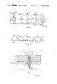
- FIG. 5is an enlarged sectional view of the access block of FIG. 2 showing a terminal passing through the block.
- FIG. 6is a schematic diagram of a lightning or surge protector for use in a protector circuit module of FIG. 1;
- FIG. 7is an electrical block diagram of the access block in circuit with a multiplexing system
- FIG. 8is a schematic diagram of another embodiment of an access block
- FIG. 9is a block diagram of a telemetry system incorporating the invention.
- FIGS. 10, 10A & 10Bare simplified block diagrams of multiplexing equipment of the system of FIG. 9.
- the system of the inventioncan be used, but is not limited to, the following applications: (1) passive services including water meter reading, gas meter reading, electric meter reading, oil consumption meter reading, and cable T.V., pay-per-view systems; (2) active services including alarm reporting from subscriber premises, peak load management, down loading of decoding algorithms for cable T.V. or direct broadcast satellite decoders; and (3) interactive services such as reverse channel for cable T.V. supported videotext, bank-at-home data services, and automated catalog ordering.
- the systemmay also be used for telephone company plant management purposes such as scanning and monitoring the status of spare cable plants, or monitoring the status of working lines to provide automatic failure reports on outside telephone plants.
- the system of the inventionincludes equipment which is located at the subscriber premise, equipment which is located in the central exchange, and adapters for interconnecting the central exchange equipment with the individual subscriber lines.
- adapterswhich will be referred to, hereinafter as access blocks due to their physical shape and their function of providing access of the multiplexing equiment to the individual subscriber lines.
- the description of the access blocksis provided with reference to the FIGS. 1-8.
- FIGS. 1 and 2there is shown a main distribution frame 20 constructed in the form generally utilized in telephone central switching offices.
- the pictorial representations presented in FIGS. 1 and 2have been stylized so as to show only those features of a main distribution frame which are essential to an understanding of the invention.
- the frame 20includes a frame member 22 that may be formed of upright legs 24 and horizontal struts 26 extending from the legs 24.
- a set of input vertical terminal blocks 28 and a set of output horizontal terminal blocks 30are supported at the outer ends of the struts 26.
- the horizontal blocks 30are used for connecting telephone lines to service functions internal to the wire center on which the external plant cables are terminated.
- An exampleis to connect to the line circuits of a telephone switching exchange 32, indicated diagrammatically, via cables 34.
- Connection of telephone lines between the vertical blocks 28 and the horizontal blocks 30is accomplished by individual flexible wire connections 36 frequently called “crossconnections" or “jumper wires.” Connection of telephone lines between the remote locations of subscribers and the vertical block 28 is accomplished by outside plant cables 38.
- a set of protector blocks 40 each carrying a set of protector circuit modules 42is positioned contiguous each vertical block 28 to provide electrical connection between the wires of the cables 38 and the modules 42.
- a complete vertical block 28includes ten (10) protector blocks 40.
- the modules 42include an arc protection circuit for discharging excess voltages to a protective ground. Such circuit is suitable for protection of the wiring in the central office from electrical discharges, such as lightning, which may strike telephone lines coupled between the remote subscriber locations and the central office.
- the vertical blocks 28serve as a connecting element whereby the individual subscriber telephone lines can be connected via well-known feed-through terminals (not shown in FIGS. 1 and 2) to terminals (not shown in FIGS. 1 and 2) of the protector block 40.
- the block 28also contains means for access to the wires for testing purposes by substitution of a test plug for the protector 42.
- an access block 44is positioned between each protector block 40 and its corresponding vertical block 28. This may be seen by a comparison of FIGS. 1 and 2.
- FIG. 1shows the arrangement prior to insertion of the access blocks 44 while
- FIG. 2shows the arrangement upon insertion of an access block 44 between a protector block 40 and a vertical block 28.
- the access block 44is made sufficiently thin, in accordance with a feature of the invention, so as to fit between a protector block 40 and a vertical block 28 without requiring any significant space in an already crowded central telephone office.
- the access blockscan be inserted without the disruption of the wiring in the harnesses 38 and 36. This management, thereby insures integrity of the telephone system during installation of the access blocks 44.
- an access blockmay be formed with the same dimensions of width and length as a protector block, it has been found to be most beneficial to construct the access blocks of a much smaller size.
- Such smaller size blockscan then be inserted as a set of the access blocks 44, as depicted in FIG. 2, side by side along the interface between a protector block 44 and its corresponding vertical blocks 28.
- the advantage of this arrangementmay be appreciated from a realization that the terminals of the protector block 44 and of the vertical block 28 may become oxidized, or otherwise roughened so as to require more physical strength, on the part of installation personnel, than would be desirable in the connection of an access block to the vertical block and to the protector block.
- the access blockshave been formed as a set of blocks 44 which are substantially smaller than either the protector block 40 or the vertical block.
- a protector block 40having five modules 42 per row, and twenty rows of the modules 42, ten access blocks 44 would be provided for each protector block 40.
- Each access block 44would contain terminals to mate with ten sets of terminals corresponding to the ten modules 42 in two rows in the array of modules 42 carried by a block 40.
- each access block 44need mate with only one-tenth of the terminals on a complete protector block 40 so as to greatly facilitate the interconnection of an access block 44 with a vertical block 28.
- the blockswould be installed one at a time in side-by-side arrangement along a vertical block 28. Thereafter, the protector block 40 would be installed upon the set of access blocks 44.
- each access block 44includes a base 46, a board 48 having a printed circuit thereon, and two multiplexers 50 constructed in the form of integrated circuit (IC) modules. All of the multiplexers 50 on the set of ten access blocks 44 supported by a single vertical block 28 are coupled via a harness 52 to a line scan unit 54 which is mounted on a leg 24 of the frame 20.
- ICintegrated circuit
- the base 46may be secured to the board 48 by an adhesive, or other well known mounting means such as screws (not shown) to provide rigidity to the block 44.
- the board 48extends beyond the end of the base 46 to provide space for housing the multiplexers 50.
- One multiplexer 50is provided for each row of the protector modules 42 and, accordingly, services five sets of telephone lines corresponding to the row of five protector modules 42 in the foregoing example of the protector block 40.
- the two multiplexers 50 in each access block 44service a total of ten subscriber telephone lines.
- Each access block 44further includes an array of feed-through terminals 56 set within the base 46, and a printed circuit 58 disposed on the board 48. Individual conductors 60 of the printed circuit 58 connect the multiplexers 50 with specific ones of the terminals 56 as will be described more fully with reference to FIGS. 3 and 6.
- Each terminal 56passes through an aperture 62 in the board 48, each aperture 62 having a metallic, cylindrical insert 64 which makes a press fit against a terminal 56 so as to insure electrical connection therewith.
- Each of the conductors 60terminates at an insert 64 to provide the foregoing electrical connection between a terminal 56 and a multiplexer 50.
- a module 42is shown to have a protector circuit having a pair of gas-discharge devices 70 and a pair of fusible-pellet devices 72 which connect the tip and ring wires to ground.
- the devices 70 and 72conduct the resulting current to ground so as to protect the equipment on the central office (C.O.) side of the module 42.
- the tip and ring wirespass from a location outside the plant (O.P.) through the blocks 28, 44, and 40, respectively, to reach the protector module 42. Thereafter, the tip and ring wires continue to pass by the blocks 40, 44 and 28, respectively, to reach the switching circuitry of the central office. Connection of the conductors 60 of a multiplexer 50 to the tip and ring wires is made in the access block 44 between the module 42 and the central office circuitry.
- FIG. 6shows a total of five terminals for the protector module 42, these corresponding to the incoming and outgoing tip and ring wires, and the ground wire. The corresponding five terminals in each set of terminals is also portrayed in FIG. 3.
- the layout of the feed-through terminals 56 in the access block 44 of FIG. 3corresponds to the arrangement of the pins (not shown) of a protector module 42.
- the connection of the conductors 60 to the tip and ring wires for the central-office side of each of the modules 42is also disclosed in FIG. 3 wherein a few exemplary ones of the conductors 60 are shown passing between the top surface of the board 48 and the bottom surface of the base 46.
- Each feed-through terminal 56is provided with a pin 66 at one end thereof and a socket 68 at the opposite end.
- the socket 68receives a pin 74, shown in phantom in FIG. 5, of the protector block 40.
- the pin 66mates with a socket 76 of the vertical block 28.
- the foregoing access blockmay be modified as shown in FIG. 8 to bring out pairs of wires to multiplexing or other circuitry for which acesss is desired. While the electric interconnection is altered thereby, the physical connection to the other blocks remains the same.
- FIG. 7shows the electrical interconnection between the many telephone subscribers who are to be serviced by the invention and a single station 78, which may also be a telephone subscriber and receive data from the many data transmitting subscribers 80.
- the telephone linepasses from the subscriber 80 via the access block 44 and a protector module 42 to the cross-switch matrix 32 and, thereafter, via an access block 44 and a protector module 42 to the station 78.
- the second communication path from the many subscribers 80 to the single subscriber station 78is via the access provided by the MUX 50 and line scan 54. From the line scan 54, connection may be completed to subscriber 78 as discussed below with reference to FIGS. 9 and 10.
- the system 100includes subscriber premises equipment 101 which includes units 102, 103 and 104.
- the unit 102provides for active services such as the interconnection with an alarm.
- the unit 103provides interconnection for interactive services.
- the unit 104provides for interconnection with encoders (not shown) of the utility meters such as water, gas and electric meters and interconnection with the telephone line 116 and a means for transmitting and receiving data over telephone lines, such as modem.
- Some form of bridged connector plug 105 at the central office main distribution frame, such as the preferred access block 44 of FIG. 2,provides for connection with a main distribution frame.
- FIG. 9Also shown in FIG. 9, is an existing central office switch 114 operator verification for test trunk interface 106 as normally provided by the particular type of central office switching equipment, a first stage multiplexer 107, a second stage multiplexer 108, a plurality of host computers 109 individual ones of which are further identified by the legends A, B, and C, and a scanner 110.
- the first stage multiplexer 107provides for interconnection of a relatively small group of telephone lines such as is provided by the multiplexer 50 of FIG. 2.
- the functions of the second stage multiplexer 108 and the scanner 110correspond to the functions of the line scan unit 54 described briefly hereinabove with reference to FIG. 2.
- the second stage multiplexer 108provides for interconnection of the analog signals from a plurality of the first stage multiplexers 107, and also provides a convenient location for any analog-to-digital conversion of these signals for subsequent communication via the scanner 110 to a host computer 109. Where only one first stage multiplexer 107 is shown in FIG. 9, it is to be understood that additional multiplexers 107 are disposed at numerous sites throughout the main distribution frame.
- the scanner 110develops the requisite address and control signals for operation of the second stage multiplexer 108, and for selecting a specific one of the first stage multiplexers 107 and an individual subscriber line connected thereto.
- lines 111 and 112by which connection is made, respectively, from the scanner 110 to the multiplexer 108 and from the scanner 110 to a host computer 109.
- a main distribution frame 113Also included within the system 100 is a main distribution frame 113, a central office switch 114, a subscriber telephone 115 coupled to a subscriber line 116 and a data bus 117 by which data and command signals are communicated between the host computers 109B, the host computer 109C, and the scanner 110.
- the subscriber telephone line 116passes from the subscriber premises equipment 101 via the main distribution frame 113 to the switch 114 for connection with other subscribers.
- a connectionis made at the plug 105 from the line 116 to the first stage multiplexer 107.
- system 100has been configured to allow expandability and adaptability to each subscriber while maintaining the integrated system concept for a given network.
- the customer subscriber premise equipment 101is a basic interface communication and control unit.
- the equipment 101provides interfaces for a multiplicity of meter encoders in any combination of gas, water, electric or other service.
- the equipment 101supports the communication and control elements for passive services and connects in parallel with the telephone line 116.
- the equipment 101can be accessed from the service provider host computer 109A, via the operator trunk interface 106, which interfaces to the trunk access mechanism of the existing central office switch 114. With such interconnection, the individual subscriber installations of the equipment 101 are to be polled for retrieval of the data supplied by the meter encoders.
- the host computer 109Aestablishes the communication path to the operator trunk, and via the trunk access matrix, to each one of the individual subscriber lines 116.
- the system 100provides a connection between service provider and subscriber that is a transparent one throughout the network from the equipment 101 to the host computer 109A.
- communication transport protocols and data rate changesmay be included in the scanner 110.
- thisallows in-band communication and signaling between the provider and the subscriber without generating traffic to the existing central office switch.
- the communication from the scanner 110may be accomplished by using in-band signalling communication via modems 104 at rates of 300-1200 baud without requiring the intervention, or use of ringing current to activate the equipment 101. This negates the need for call-discrimination techniques at the subscriber site.
- each subscriber linecan be polled often thereby allowing for retrieval of data from the meter encoders at rates much higher than those currently attained by manual methods.
- the unit 102When a given subscriber location requires provision for supporting active services, the unit 102 is incorporated within the equipment 101. This allows interfacing with the aforementioned alarm signal and the provision of an alarm input and output ports as well as control ports of the unit 102. Communication is accomplished by use of the transmission and control mechanisms available in the equipment 101 in the same fashion as described for the passive services.
- each one of the subscriber linesis connected to the subscriber data network, the data made available by the equipment 101 from the main distribution frame utilizing the connector plug 105.
- the plug 105interfaces to the multiplexers 107-108 and the scanner 110 which controls the overall operation and communication of a group of subscriber lines.
- the scanner 110may be viewed as an interfacing of a group of lines to the whole communication network for attaining access to and from the host computers 109.
- the computers 109represent the service providers and customers for the active services.
- This implementation of the system 100is also capable of supporting the passive services thereby eliminating the need for the trunk access 106 which is useful when only passive services are to be provided.
- the foregoing use of the system 100also permits expansion from small systems and small exchanges to larger systems and larger exchanges.
- the cabling and installation proceduresare facilitated by use of the plug 105, actually a set of plugs wherein one plug is used for each group of subscriber lines as described above with respect to the preferred use of the access block 44.
- incorporation of the unit 103 within the equipment 101provides for connection of data interfacing devices of the subscriber to the system 100.
- the unit 103makes use of the transmission and control mechanism of the equipment 101 for the passive services and, in applications which so require, allows direct interfacing to the telephone line.
- Transmission from the interactive service unit 103is accomplished by means of simultaneous voice plus data, such as data over voice, techniques wherein modulated data is transported over the telephone line in a frequency band above the voice band, thereby to permit the two forms of communication to occur simultaneously.
- the data over voice informationis extracted at the main distribution frame 113 via the adaptive connection 105 and the first stage multiplexer 107 handling those lines, with the appropriate class of service and with filters for separating the bands of interest.
- a serial blocking filteris needed to prevent the data signals from interfering with the voice signals into the telephone central office switch.
- the design of the adaptorallows for insertion of same without disrupting the existing wiring at the main distribution frame.
- the datacan be extracted and fed into the second stage multiplexer 108 which, in turn, transmits the data through the scanner 110 and into the communication network.
- the datais coupled via the communication network, in particular the bus 117, to a host computer 109 allowing control and access interfacing to the data service providers.
- the data-over-voice transmissionpermits two-way communication between the service providers via the host computers and the communication network, the scanner, and the multiplexer units 107-108 associated with the particular telephone lines 116.
- the equipment 101With respect to the construction of the equipment 101, it is constructed as a self-contained functional module which is located at the end of the subscriber telephone line and physically placed in or outside the subscriber dwelling.
- the unit 101provides line transmission interfacing, power extraction from the telephone line, means such as modems or a dual tone multi-frequency transmitter for transmitting and receiving modulated data, and, preferably, is provided further with a supervision and signalling control mechanism in the form of a microprocessor which provides intelligence for the units to communicate with the network of the system 100 and to receive and interpret the commands for interrogating the meter encoders which may be attached to the input ports of the equipment 101.
- the microprocessor (not shown) of the equipment 101contains the complete program necessary to handle both the communication protocols over the telephone line as well as for detecting internally-generated alarms such as an alarm indicating external tampering with the box which encloses the equipment 101, as well as an alarm indicating loss of power, or low battery conditions.
- the equipment 101also includes the necessary programs to handle the individual protocol of multiple meter encoders to allow flexibility of interfacing units in the field.
- the equipment 101connects in parallel with a telephone line in the same way as the telephone set 115, and the electrical behavior of the equipment 101 is of high impedance in the transmission inactive states to avoid interference with the normal telephone service.
- the unit 102is a self-contained module which provides input and output ports for alarm reporting equipment.
- the unit 102also provides output drivers to provide control functions and furthermore provides means for connecting external power means for the interfacing circuitry within the unit 102.
- the unit 102includes an interface port compatible with the other equipment of the unit 101 to allow communication with such other equipment.
- the active service unit 102generates an inaudible pilot signal that is sent over the telephone line 116 to allow monitoring of the line, thereby to ensure continuous monitoring of both the communication channel and the equipment 101 for detecting of alarms in the event of failure of any of the communication elements.
- the interactive service unit 103has the capability of interfacing with other circuitry of the equipment 101, or directly with the telephone line 116 so as to provide a data port for an RS232 type of compatible data port by the subscriber.
- the unit 103is microprocessor based and utilizes local sourced power for its operation.
- the unit 103includes interfaces for control and transmission handshaking with the equipment 101 for alarm reporting in the event of failure.
- the equipment 101is constructed to use an existing 2-wire telephone line by means of parallel connection to conventional analog telephones. Another embodiment allows it to connect directly to the designated telemetry channel of a telephone which uses digital techniques as in the Integrated Services Digital Network standard "D" channel as described in CCITT standards.
- FIG. 10there is shown a simplified block diagram of one embodiment of the multiplexers 107-108 and the scanner 110 each of which includes well-known components, the showing of FIG. 10 being sufficient to explain further the general operation of the multiplexers 107-108 and the scanner 110.
- individual subscriber telephone lines 116are coupled by a pair of electrically operated switches 118, such as that disclosed in the U.S. Pat. No. 4,170,740 issued in the name of Pernyeszi on Oct. 9, 1979 and assigned to the assignee hereof. These switches permit full access to the line bandwidth by the common line 126 when the pair of switches are closed.
- the multiplexer 107further includes a switch 120 which applies a voltage V to selected ones of the switches 118 to operate the selected switches 118.
- the switch 120is, in turn, activated by a digital signal from a decoder 122.
- the decoder 122is responsive to a digital control signal on line 124 for directing the switch 120 to operate the pair of switches 118 in accordance with the construction provided on the line 124.
- the second stage multiplexer 108includes a set of interface units 128, a set of analog-to-digital converters 130, a set of digital-to-analog converters 132, a set of storage units 134, a switch 136 and a decoder 138.
- the interface unit 128couples the converters 130 and 132 to the interface line 126 associated with each of the multiplexers 107.
- Outgoing signals propagating along the line 126 from a subscriberare coupled to the converter 130 which converts these signals to digital format for storage in the storage unit 134.
- incoming signals in a digital format stored in the storage unit 134are converted by the converter 132 to analog format, and are then applied via the interface units 128 to the line 126 for transmission to the subscriber.
- the address of the specific subscriber from which data is being received from or to which data is being transmitted,is also stored within a storage unit 134 coupled to the line 124.
- the storage units 134contain ingoing data, outgoing data, and the address of the subscriber associated with the foregoing data.
- the use of the storage units 134permits the reception of data at a storage unit 134 and the transmission of data from a storage unit 134 to be done at different rates. This is accomplished by strobing the storage units 134 with clock pulses from a timing unit activated by signals from the decoder 138.
- the switch 136is also operated by a digital signal from the decoder 138.
- the decoder 138is responsive to incoming digitized command signals provided by the scanner 110 via incoming data bus 111.
- the decoder 138decodes the instructions on the bus 111 to operate the switch 136 and to activate the timing unit 140.
- signals from the set of storage units 134 corresponding to the selected telephone subscriberare coupled via the switch 136 to the bus 111 and by the bus 111 to the scanner 110.
- control signals and data signals for individual ones of the subscribersare connected from the scanner 110 via the switch 136 to the communication channel associated with the selected subscriber. It is noted that each of these communication channels is identical, each channel having the three storage units 134, the two converters 130 and 132 and the interface unit 128.
- the scanner 110includes an incoming memory, an outgoing memory 144, a packet assembler 146, a packet disassembler 148, a decoder 150, two address generators 151-152, and a microprocessor 154.
- the memory 142processes information coming from a host computer 109 via line 112 (a data bus) for subsequent reception at a telephone subscriber.
- the memory 144is used in the processing of outgoing data from the telephone subscriber via line 112 and bus 117 to a host computer 109.
- the memories 142 and 144are addressed by the generators 151-152, respectively in response to control signals applied to the generators 151-152 by the microprocessor 154.
- the decoder 150detects the presence of an incoming message directed to the scanner 110 from the bus 117 and activates the microprocessor 154 to operate the generator 151 to address a slot in the memory 142 for receiving the incoming data.
- the incoming dataarrives as a packet along the bus 117 and is first rearranged in a format suitable for storage in the memory 142 by the packet disassembler 148, such packetizing circuitry being well-known.
- the packet disassembler 148is activated by a signal from the decoder 150 in response to the detection of an incoming message directed to the scanner 110.
- the packet assembler 146is activated by the microprocessor 154 to extract data from the memory 144, the data being extracted from a slot addressed by the generator 152, to place the extracted data in proper format for transmittal along the bus 117.
- the proper formatinvolves packetizing the data with the address of the host computer 109, the identity of the water meter or gas meter, or alarm, or interactive service, as well as the identity of the subscriber. These various identities, along with the data, are arranged in a preset format of packet by the packet assembler 146, under instruction from the microprocessor 154.
- the microprocessor 154is responsive to signals provided by each of the memories 142 and 144 corresponding to addresses applied thereto, the signals indicating the presence of data stored within the respective memories, which data is to be processed.
- the microprocessor 154is also programmed to recognize the presence of the pilot tone from an alarm circuit so as to immediately direct the transmission of the alarm by the packet assembler 146 to the appropriate host computer 109.
- FIG. 10provides for a carrying out of the purposes of the invention and enables the system 100 to operate in the manner described above.
- a filter 156may be inserted on the line 126.
- the filter 156has a pass band which envelopes the spectrum of the data and lies outside the voice spectrum so as to separate the two signals from the multiplexing process.
Landscapes
- Engineering & Computer Science (AREA)
- Signal Processing (AREA)
- Telephonic Communication Services (AREA)
- Selective Calling Equipment (AREA)
- Data Exchanges In Wide-Area Networks (AREA)
Abstract
Description
Claims (12)
Priority Applications (4)
| Application Number | Priority Date | Filing Date | Title |
|---|---|---|---|
| US06/648,542US4665516A (en) | 1984-09-07 | 1984-09-07 | Information transport system employing telephone lines |
| EP85306290AEP0176273B1 (en) | 1984-09-07 | 1985-09-05 | Information transport system employing telephone lines |
| JP60197485AJPS6367066A (en) | 1984-09-07 | 1985-09-06 | Information transmission system utilizing telephone line |
| ES546750AES8800555A1 (en) | 1984-09-07 | 1985-09-06 | Information transport system employing telephone lines. |
Applications Claiming Priority (1)
| Application Number | Priority Date | Filing Date | Title |
|---|---|---|---|
| US06/648,542US4665516A (en) | 1984-09-07 | 1984-09-07 | Information transport system employing telephone lines |
Publications (1)
| Publication Number | Publication Date |
|---|---|
| US4665516Atrue US4665516A (en) | 1987-05-12 |
Family
ID=24601216
Family Applications (1)
| Application Number | Title | Priority Date | Filing Date |
|---|---|---|---|
| US06/648,542Expired - LifetimeUS4665516A (en) | 1984-09-07 | 1984-09-07 | Information transport system employing telephone lines |
Country Status (4)
| Country | Link |
|---|---|
| US (1) | US4665516A (en) |
| EP (1) | EP0176273B1 (en) |
| JP (1) | JPS6367066A (en) |
| ES (1) | ES8800555A1 (en) |
Cited By (37)
| Publication number | Priority date | Publication date | Assignee | Title |
|---|---|---|---|---|
| US4872198A (en)* | 1988-08-12 | 1989-10-03 | The Intleplex Corp. | Transient signal elimination circuit for telecommunications applications |
| US4974252A (en)* | 1987-06-03 | 1990-11-27 | Club Theatre Network, Inc. | Interactive commercial/entertainment network |
| US5034902A (en)* | 1986-12-09 | 1991-07-23 | Srg Schweizerische Radio-Und Fernsehgesellschaft | Method and system for ascertaining the consumption habits of a test population |
| US5369691A (en)* | 1993-03-04 | 1994-11-29 | Utilex, Inc. | Telephonic information communication method and apparatus |
| US5588140A (en)* | 1993-03-15 | 1996-12-24 | Computer Network Technology Corporation | Transparent extension of peripheral from host |
| WO1998015079A1 (en)* | 1996-09-30 | 1998-04-09 | Mci Communications Corporation | Method of and system for intelligent access line protect switching |
| US5869821A (en)* | 1993-10-13 | 1999-02-09 | Samsung Electronics Co., Ltd. | Credit inquiry service system and method |
| US6381227B1 (en) | 1993-06-17 | 2002-04-30 | Gilat Florida Inc. | Frame relay protocol-based multiplex switching scheme for satellite mesh network |
| US20020071531A1 (en)* | 1989-07-14 | 2002-06-13 | Inline Connections Corporation, A Virginia Corporation | Video transmission and control system utilizing internal telephone lines |
| US20030147513A1 (en)* | 1999-06-11 | 2003-08-07 | Goodman David D. | High-speed data communication over a residential telephone wiring network |
| US20030165220A1 (en)* | 1989-07-14 | 2003-09-04 | Goodman David D. | Distributed splitter for data transmission over twisted wire pairs |
| US6771617B1 (en) | 1993-06-17 | 2004-08-03 | Gilat Satellite Networks, Ltd. | Frame relay protocol-based multiplex switching scheme for satellite mesh network |
| US20040199909A1 (en)* | 1999-07-27 | 2004-10-07 | Inline Connection Corporation | Universal serial bus adapter with automatic installation |
| US20040230710A1 (en)* | 1999-07-27 | 2004-11-18 | Inline Connection Corporation | System and method of automatic installation of computer peripherals |
| US6847611B1 (en) | 1990-12-10 | 2005-01-25 | At&T Corp. | Traffic management for frame relay switched data service |
| US20060104273A1 (en)* | 1997-07-03 | 2006-05-18 | At&T Corp. | Frame relay switched data service |
| US20060197428A1 (en)* | 2005-02-21 | 2006-09-07 | Takeshi Tonegawa | Electron devices with non-evaporation-type getters and method for manufacturing the same |
| US7274688B2 (en) | 2000-04-18 | 2007-09-25 | Serconet Ltd. | Telephone communication system over a single telephone line |
| US7301944B1 (en) | 1997-10-24 | 2007-11-27 | Tranz-Send Broadcasting Network, Inc. | Media file distribution with adaptive transmission protocols |
| US7317793B2 (en) | 2003-01-30 | 2008-01-08 | Serconet Ltd | Method and system for providing DC power on local telephone lines |
| US7436842B2 (en) | 2001-10-11 | 2008-10-14 | Serconet Ltd. | Outlet with analog signal adapter, a method for use thereof and a network using said outlet |
| US7483524B2 (en) | 1999-07-20 | 2009-01-27 | Serconet, Ltd | Network for telephony and data communication |
| US7522714B2 (en) | 2000-03-20 | 2009-04-21 | Serconet Ltd. | Telephone outlet for implementing a local area network over telephone lines and a local area network using such outlets |
| US7542554B2 (en) | 2001-07-05 | 2009-06-02 | Serconet, Ltd | Telephone outlet with packet telephony adapter, and a network using same |
| US7587001B2 (en) | 2006-01-11 | 2009-09-08 | Serconet Ltd. | Apparatus and method for frequency shifting of a wireless signal and systems using frequency shifting |
| US7633966B2 (en) | 2000-04-19 | 2009-12-15 | Mosaid Technologies Incorporated | Network combining wired and non-wired segments |
| US7686653B2 (en) | 2003-09-07 | 2010-03-30 | Mosaid Technologies Incorporated | Modular outlet |
| US20100309931A1 (en)* | 2007-10-22 | 2010-12-09 | Mobileaccess Networks Ltd. | Communication system using low bandwidth wires |
| US7873058B2 (en) | 2004-11-08 | 2011-01-18 | Mosaid Technologies Incorporated | Outlet with analog signal adapter, a method for use thereof and a network using said outlet |
| US20110170476A1 (en)* | 2009-02-08 | 2011-07-14 | Mobileaccess Networks Ltd. | Communication system using cables carrying ethernet signals |
| US8175649B2 (en) | 2008-06-20 | 2012-05-08 | Corning Mobileaccess Ltd | Method and system for real time control of an active antenna over a distributed antenna system |
| US8238328B2 (en) | 2003-03-13 | 2012-08-07 | Mosaid Technologies Incorporated | Telephone system having multiple distinct sources and accessories therefor |
| US8270430B2 (en) | 1998-07-28 | 2012-09-18 | Mosaid Technologies Incorporated | Local area network of serial intelligent cells |
| US8325759B2 (en) | 2004-05-06 | 2012-12-04 | Corning Mobileaccess Ltd | System and method for carrying a wireless based signal over wiring |
| US9184960B1 (en) | 2014-09-25 | 2015-11-10 | Corning Optical Communications Wireless Ltd | Frequency shifting a communications signal(s) in a multi-frequency distributed antenna system (DAS) to avoid or reduce frequency interference |
| US9338823B2 (en) | 2012-03-23 | 2016-05-10 | Corning Optical Communications Wireless Ltd | Radio-frequency integrated circuit (RFIC) chip(s) for providing distributed antenna system functionalities, and related components, systems, and methods |
| US10986164B2 (en) | 2004-01-13 | 2021-04-20 | May Patents Ltd. | Information device |
Citations (7)
| Publication number | Priority date | Publication date | Assignee | Title |
|---|---|---|---|---|
| US3922490A (en)* | 1973-06-18 | 1975-11-25 | Charles D Pettis | Alarm and utility meter reading system employing telephone lines |
| US3937889A (en)* | 1973-01-15 | 1976-02-10 | Sperry Rand Corporation | Data communication apparatus for use in a telephone system |
| US4171467A (en)* | 1978-07-20 | 1979-10-16 | Bell Telephone Laboratories, Incorporated | Signal multiplexing circuit |
| US4225967A (en)* | 1978-01-09 | 1980-09-30 | Fujitsu Limited | Broadcast acknowledgement method and system |
| US4399440A (en)* | 1981-02-17 | 1983-08-16 | Sparton Corporation | Addressable transducer with a variable frequency oscillation for monitoring a physical quantity |
| US4449218A (en)* | 1980-10-24 | 1984-05-15 | Siemens Aktiengesellschaft | Analog/digital telecommunication subscriber station |
| US4504831A (en)* | 1981-10-09 | 1985-03-12 | Systems And Support, Incorporated | Utility usage data and event data acquisition system |
Family Cites Families (10)
| Publication number | Priority date | Publication date | Assignee | Title |
|---|---|---|---|---|
| DE1964257B2 (en)* | 1969-12-22 | 1976-11-18 | Robert Bosch Gmbh, 7000 Stuttgart | METHOD AND ARRANGEMENT FOR ESTABLISHING A CONNECTION PATH FOR VIDEO SIGNALS |
| DE2146887B2 (en)* | 1971-09-20 | 1975-01-16 | Telefonbau Und Normalzeit Gmbh, 6000 Frankfurt | Video telephone extension system has series binary data - coded uses two positive and two negative half-waves representing two logical levels |
| US3821705A (en)* | 1972-10-12 | 1974-06-28 | Concord Computing Corp | Data communication system and apparatus |
| JPS5638858Y2 (en)* | 1978-03-16 | 1981-09-10 | ||
| JPS5528606A (en)* | 1978-08-21 | 1980-02-29 | Nippon Telegr & Teleph Corp <Ntt> | Transmission system of subscriber line |
| DE2930795A1 (en)* | 1979-07-28 | 1981-02-12 | Standard Elektrik Lorenz Ag | Central telephone exchange for televised data pages and other channels - has separate information and control buses for coupling networks and data conversion modules |
| GB2098027B (en)* | 1981-04-30 | 1984-11-28 | Standard Telephones Cables Ltd | Telephone exchange |
| DE3130410A1 (en)* | 1981-07-31 | 1983-02-17 | Siemens AG, 1000 Berlin und 8000 München | Analog/digital telecommunications system |
| DE3143010A1 (en)* | 1981-10-29 | 1983-05-05 | Siemens AG, 1000 Berlin und 8000 München | Circuit arrangement for telecommunications exchanges, in particular telephone exchanges, with communication routes for connections of conventional bandwidth and for connections of larger bandwidth |
| GB2132446A (en)* | 1982-12-01 | 1984-07-04 | Standard Telephones Cables Ltd | Telecommunication exchange system |
- 1984
- 1984-09-07USUS06/648,542patent/US4665516A/ennot_activeExpired - Lifetime
- 1985
- 1985-09-05EPEP85306290Apatent/EP0176273B1/ennot_activeExpired
- 1985-09-06ESES546750Apatent/ES8800555A1/ennot_activeExpired
- 1985-09-06JPJP60197485Apatent/JPS6367066A/enactiveGranted
Patent Citations (7)
| Publication number | Priority date | Publication date | Assignee | Title |
|---|---|---|---|---|
| US3937889A (en)* | 1973-01-15 | 1976-02-10 | Sperry Rand Corporation | Data communication apparatus for use in a telephone system |
| US3922490A (en)* | 1973-06-18 | 1975-11-25 | Charles D Pettis | Alarm and utility meter reading system employing telephone lines |
| US4225967A (en)* | 1978-01-09 | 1980-09-30 | Fujitsu Limited | Broadcast acknowledgement method and system |
| US4171467A (en)* | 1978-07-20 | 1979-10-16 | Bell Telephone Laboratories, Incorporated | Signal multiplexing circuit |
| US4449218A (en)* | 1980-10-24 | 1984-05-15 | Siemens Aktiengesellschaft | Analog/digital telecommunication subscriber station |
| US4399440A (en)* | 1981-02-17 | 1983-08-16 | Sparton Corporation | Addressable transducer with a variable frequency oscillation for monitoring a physical quantity |
| US4504831A (en)* | 1981-10-09 | 1985-03-12 | Systems And Support, Incorporated | Utility usage data and event data acquisition system |
Cited By (119)
| Publication number | Priority date | Publication date | Assignee | Title |
|---|---|---|---|---|
| US5034902A (en)* | 1986-12-09 | 1991-07-23 | Srg Schweizerische Radio-Und Fernsehgesellschaft | Method and system for ascertaining the consumption habits of a test population |
| US4974252A (en)* | 1987-06-03 | 1990-11-27 | Club Theatre Network, Inc. | Interactive commercial/entertainment network |
| US4872198A (en)* | 1988-08-12 | 1989-10-03 | The Intleplex Corp. | Transient signal elimination circuit for telecommunications applications |
| WO1990001841A1 (en)* | 1988-08-12 | 1990-02-22 | The Inteleplex Corporation | Transient signal eliminating circuit for telecommunications applications |
| US4980911A (en)* | 1988-08-12 | 1990-12-25 | The Inteleplex Corporation | Transient signal elimination circuit for telecommunications applications with CPU control means |
| US7149289B2 (en) | 1989-07-14 | 2006-12-12 | Inline Connection Corporation | Interactive data over voice communication system and method |
| US7224780B2 (en) | 1989-07-14 | 2007-05-29 | Inline Connection Corporation | Multichannel transceiver using redundant encoding and strategic channel spacing |
| US7577240B2 (en) | 1989-07-14 | 2009-08-18 | Inline Connection Corporation | Two-way communication over a single transmission line between one or more information sources and a group of telephones, computers, and televisions |
| US20020071531A1 (en)* | 1989-07-14 | 2002-06-13 | Inline Connections Corporation, A Virginia Corporation | Video transmission and control system utilizing internal telephone lines |
| US6970537B2 (en) | 1989-07-14 | 2005-11-29 | Inline Connection Corporation | Video transmission and control system utilizing internal telephone lines |
| US20030165220A1 (en)* | 1989-07-14 | 2003-09-04 | Goodman David D. | Distributed splitter for data transmission over twisted wire pairs |
| US7227932B2 (en) | 1989-07-14 | 2007-06-05 | Inline Connection Corporation | Multi-band data over voice communication system and method |
| US20050117721A1 (en)* | 1989-07-14 | 2005-06-02 | Goodman David D. | Video transmission and control system utilizing internal telephone lines |
| US20050117722A1 (en)* | 1989-07-14 | 2005-06-02 | Inline Connection Corporation | Video transmission and control system utilizing internal telephone lines |
| US6847611B1 (en) | 1990-12-10 | 2005-01-25 | At&T Corp. | Traffic management for frame relay switched data service |
| US20080284840A1 (en)* | 1991-12-05 | 2008-11-20 | Inline Connection Corporation | Method, System and Apparatus for Voice and Data Transmission Over A Conductive Path |
| US5369691A (en)* | 1993-03-04 | 1994-11-29 | Utilex, Inc. | Telephonic information communication method and apparatus |
| US5588140A (en)* | 1993-03-15 | 1996-12-24 | Computer Network Technology Corporation | Transparent extension of peripheral from host |
| US6625130B2 (en) | 1993-06-17 | 2003-09-23 | Gilat Satellite Networks, Ltd. | Frame relay protocol-based multiplex switching scheme for satellite mesh network |
| US20040240406A1 (en)* | 1993-06-17 | 2004-12-02 | Gilat Satellite Networks, Ltd. | Frame relay protocol-based multiplex switching scheme for satellite mesh network |
| US7583626B2 (en) | 1993-06-17 | 2009-09-01 | Gilat Satellite Networks, Ltd. | Multiplex switching scheme for communications network |
| US20090316618A1 (en)* | 1993-06-17 | 2009-12-24 | Gilat Satellite Networks, Ltd. | Multiplex Switching Scheme for Communications Network |
| US6771617B1 (en) | 1993-06-17 | 2004-08-03 | Gilat Satellite Networks, Ltd. | Frame relay protocol-based multiplex switching scheme for satellite mesh network |
| US8068472B2 (en) | 1993-06-17 | 2011-11-29 | Gilat Satellite Networks, Ltd | Multiplex switching scheme for communications network |
| US6381227B1 (en) | 1993-06-17 | 2002-04-30 | Gilat Florida Inc. | Frame relay protocol-based multiplex switching scheme for satellite mesh network |
| US7321572B2 (en) | 1993-06-17 | 2008-01-22 | Gilat Satellite Networks, Ltd. | Frame relay protocol-based multiplex switching scheme for satellite mesh network |
| US5869821A (en)* | 1993-10-13 | 1999-02-09 | Samsung Electronics Co., Ltd. | Credit inquiry service system and method |
| US5796718A (en)* | 1996-09-30 | 1998-08-18 | Mci Communications Corporation | Method of and system for intelligent access line protect switching |
| WO1998015079A1 (en)* | 1996-09-30 | 1998-04-09 | Mci Communications Corporation | Method of and system for intelligent access line protect switching |
| US7668095B2 (en) | 1997-07-03 | 2010-02-23 | At&T Corp. | Traffic management for frame relay switched data service |
| US20060104273A1 (en)* | 1997-07-03 | 2006-05-18 | At&T Corp. | Frame relay switched data service |
| US8717896B2 (en) | 1997-07-03 | 2014-05-06 | At&T Intellectual Property Ii, L.P. | Frame relay switched data service |
| US20100157805A1 (en)* | 1997-07-03 | 2010-06-24 | Chase Christopher J | Traffic management for frame relay switched data service |
| US8014286B2 (en) | 1997-07-03 | 2011-09-06 | At&T Intellectual Property Ii, L.P. | Frame relay switched data service |
| US8027257B2 (en) | 1997-07-03 | 2011-09-27 | At&T Intellectual Property Ii, L.P. | Traffic management for frame relay switched data service |
| US7668168B2 (en) | 1997-07-03 | 2010-02-23 | At&T Corp. | Frame relay switched data service |
| US7257118B2 (en) | 1997-07-03 | 2007-08-14 | At&T Corp. | Frame relay switched data service |
| US20050105466A1 (en)* | 1997-07-03 | 2005-05-19 | Chase Christopher J. | Traffic management for frame relay switched data service |
| US20090041022A1 (en)* | 1997-07-03 | 2009-02-12 | Chase Christopher J | Frame relay switched data service |
| US9276849B2 (en) | 1997-07-03 | 2016-03-01 | At&T Intellectual Property Ii, L.P. | Frame relay switched data service |
| US7463627B1 (en) | 1997-07-03 | 2008-12-09 | At&T Corp. | Frame relay switched data service |
| US20080120430A1 (en)* | 1997-10-24 | 2008-05-22 | Redmond Scott D | Peered Content Distribution |
| US7301944B1 (en) | 1997-10-24 | 2007-11-27 | Tranz-Send Broadcasting Network, Inc. | Media file distribution with adaptive transmission protocols |
| US8325636B2 (en) | 1998-07-28 | 2012-12-04 | Mosaid Technologies Incorporated | Local area network of serial intelligent cells |
| US8885659B2 (en) | 1998-07-28 | 2014-11-11 | Conversant Intellectual Property Management Incorporated | Local area network of serial intelligent cells |
| US8867523B2 (en) | 1998-07-28 | 2014-10-21 | Conversant Intellectual Property Management Incorporated | Local area network of serial intelligent cells |
| US8908673B2 (en) | 1998-07-28 | 2014-12-09 | Conversant Intellectual Property Management Incorporated | Local area network of serial intelligent cells |
| US8885660B2 (en) | 1998-07-28 | 2014-11-11 | Conversant Intellectual Property Management Incorporated | Local area network of serial intelligent cells |
| US8270430B2 (en) | 1998-07-28 | 2012-09-18 | Mosaid Technologies Incorporated | Local area network of serial intelligent cells |
| US20030147513A1 (en)* | 1999-06-11 | 2003-08-07 | Goodman David D. | High-speed data communication over a residential telephone wiring network |
| US7145990B2 (en) | 1999-06-11 | 2006-12-05 | Inline Connection Corporation | High-speed data communication over a residential telephone wiring network |
| US8929523B2 (en) | 1999-07-20 | 2015-01-06 | Conversant Intellectual Property Management Inc. | Network for telephony and data communication |
| US8351582B2 (en) | 1999-07-20 | 2013-01-08 | Mosaid Technologies Incorporated | Network for telephony and data communication |
| US7492875B2 (en) | 1999-07-20 | 2009-02-17 | Serconet, Ltd. | Network for telephony and data communication |
| US7483524B2 (en) | 1999-07-20 | 2009-01-27 | Serconet, Ltd | Network for telephony and data communication |
| US7522713B2 (en) | 1999-07-20 | 2009-04-21 | Serconet, Ltd. | Network for telephony and data communication |
| US20040199909A1 (en)* | 1999-07-27 | 2004-10-07 | Inline Connection Corporation | Universal serial bus adapter with automatic installation |
| US20040230710A1 (en)* | 1999-07-27 | 2004-11-18 | Inline Connection Corporation | System and method of automatic installation of computer peripherals |
| US8855277B2 (en) | 2000-03-20 | 2014-10-07 | Conversant Intellectual Property Managment Incorporated | Telephone outlet for implementing a local area network over telephone lines and a local area network using such outlets |
| US7715534B2 (en) | 2000-03-20 | 2010-05-11 | Mosaid Technologies Incorporated | Telephone outlet for implementing a local area network over telephone lines and a local area network using such outlets |
| US8363797B2 (en) | 2000-03-20 | 2013-01-29 | Mosaid Technologies Incorporated | Telephone outlet for implementing a local area network over telephone lines and a local area network using such outlets |
| US7522714B2 (en) | 2000-03-20 | 2009-04-21 | Serconet Ltd. | Telephone outlet for implementing a local area network over telephone lines and a local area network using such outlets |
| US8559422B2 (en) | 2000-04-18 | 2013-10-15 | Mosaid Technologies Incorporated | Telephone communication system over a single telephone line |
| US8223800B2 (en) | 2000-04-18 | 2012-07-17 | Mosaid Technologies Incorporated | Telephone communication system over a single telephone line |
| US7397791B2 (en) | 2000-04-18 | 2008-07-08 | Serconet, Ltd. | Telephone communication system over a single telephone line |
| US8000349B2 (en) | 2000-04-18 | 2011-08-16 | Mosaid Technologies Incorporated | Telephone communication system over a single telephone line |
| US7274688B2 (en) | 2000-04-18 | 2007-09-25 | Serconet Ltd. | Telephone communication system over a single telephone line |
| US7593394B2 (en) | 2000-04-18 | 2009-09-22 | Mosaid Technologies Incorporated | Telephone communication system over a single telephone line |
| US7466722B2 (en) | 2000-04-18 | 2008-12-16 | Serconet Ltd | Telephone communication system over a single telephone line |
| US7633966B2 (en) | 2000-04-19 | 2009-12-15 | Mosaid Technologies Incorporated | Network combining wired and non-wired segments |
| US8848725B2 (en) | 2000-04-19 | 2014-09-30 | Conversant Intellectual Property Management Incorporated | Network combining wired and non-wired segments |
| US8867506B2 (en) | 2000-04-19 | 2014-10-21 | Conversant Intellectual Property Management Incorporated | Network combining wired and non-wired segments |
| US8873575B2 (en) | 2000-04-19 | 2014-10-28 | Conversant Intellectual Property Management Incorporated | Network combining wired and non-wired segments |
| US8873586B2 (en) | 2000-04-19 | 2014-10-28 | Conversant Intellectual Property Management Incorporated | Network combining wired and non-wired segments |
| US8982904B2 (en) | 2000-04-19 | 2015-03-17 | Conversant Intellectual Property Management Inc. | Network combining wired and non-wired segments |
| US8472593B2 (en) | 2001-07-05 | 2013-06-25 | Mosaid Technologies Incorporated | Telephone outlet with packet telephony adaptor, and a network using same |
| US7542554B2 (en) | 2001-07-05 | 2009-06-02 | Serconet, Ltd | Telephone outlet with packet telephony adapter, and a network using same |
| US8761186B2 (en) | 2001-07-05 | 2014-06-24 | Conversant Intellectual Property Management Incorporated | Telephone outlet with packet telephony adapter, and a network using same |
| US7769030B2 (en) | 2001-07-05 | 2010-08-03 | Mosaid Technologies Incorporated | Telephone outlet with packet telephony adapter, and a network using same |
| US7680255B2 (en) | 2001-07-05 | 2010-03-16 | Mosaid Technologies Incorporated | Telephone outlet with packet telephony adaptor, and a network using same |
| US7889720B2 (en) | 2001-10-11 | 2011-02-15 | Mosaid Technologies Incorporated | Outlet with analog signal adapter, a method for use thereof and a network using said outlet |
| US7453895B2 (en) | 2001-10-11 | 2008-11-18 | Serconet Ltd | Outlet with analog signal adapter, a method for use thereof and a network using said outlet |
| US7436842B2 (en) | 2001-10-11 | 2008-10-14 | Serconet Ltd. | Outlet with analog signal adapter, a method for use thereof and a network using said outlet |
| US7953071B2 (en) | 2001-10-11 | 2011-05-31 | Mosaid Technologies Incorporated | Outlet with analog signal adapter, a method for use thereof and a network using said outlet |
| US7860084B2 (en) | 2001-10-11 | 2010-12-28 | Mosaid Technologies Incorporated | Outlet with analog signal adapter, a method for use thereof and a network using said outlet |
| US7702095B2 (en) | 2003-01-30 | 2010-04-20 | Mosaid Technologies Incorporated | Method and system for providing DC power on local telephone lines |
| US8107618B2 (en) | 2003-01-30 | 2012-01-31 | Mosaid Technologies Incorporated | Method and system for providing DC power on local telephone lines |
| US8787562B2 (en) | 2003-01-30 | 2014-07-22 | Conversant Intellectual Property Management Inc. | Method and system for providing DC power on local telephone lines |
| US7317793B2 (en) | 2003-01-30 | 2008-01-08 | Serconet Ltd | Method and system for providing DC power on local telephone lines |
| US8238328B2 (en) | 2003-03-13 | 2012-08-07 | Mosaid Technologies Incorporated | Telephone system having multiple distinct sources and accessories therefor |
| US7867035B2 (en) | 2003-07-09 | 2011-01-11 | Mosaid Technologies Incorporated | Modular outlet |
| US8360810B2 (en) | 2003-09-07 | 2013-01-29 | Mosaid Technologies Incorporated | Modular outlet |
| US8235755B2 (en) | 2003-09-07 | 2012-08-07 | Mosaid Technologies Incorporated | Modular outlet |
| US8591264B2 (en) | 2003-09-07 | 2013-11-26 | Mosaid Technologies Incorporated | Modular outlet |
| US8092258B2 (en) | 2003-09-07 | 2012-01-10 | Mosaid Technologies Incorporated | Modular outlet |
| US7686653B2 (en) | 2003-09-07 | 2010-03-30 | Mosaid Technologies Incorporated | Modular outlet |
| US11095708B2 (en) | 2004-01-13 | 2021-08-17 | May Patents Ltd. | Information device |
| US10986164B2 (en) | 2004-01-13 | 2021-04-20 | May Patents Ltd. | Information device |
| US10986165B2 (en) | 2004-01-13 | 2021-04-20 | May Patents Ltd. | Information device |
| US11032353B2 (en) | 2004-01-13 | 2021-06-08 | May Patents Ltd. | Information device |
| US8325759B2 (en) | 2004-05-06 | 2012-12-04 | Corning Mobileaccess Ltd | System and method for carrying a wireless based signal over wiring |
| US7873058B2 (en) | 2004-11-08 | 2011-01-18 | Mosaid Technologies Incorporated | Outlet with analog signal adapter, a method for use thereof and a network using said outlet |
| US20060197428A1 (en)* | 2005-02-21 | 2006-09-07 | Takeshi Tonegawa | Electron devices with non-evaporation-type getters and method for manufacturing the same |
| US7587001B2 (en) | 2006-01-11 | 2009-09-08 | Serconet Ltd. | Apparatus and method for frequency shifting of a wireless signal and systems using frequency shifting |
| US8184681B2 (en) | 2006-01-11 | 2012-05-22 | Corning Mobileaccess Ltd | Apparatus and method for frequency shifting of a wireless signal and systems using frequency shifting |
| US7813451B2 (en) | 2006-01-11 | 2010-10-12 | Mobileaccess Networks Ltd. | Apparatus and method for frequency shifting of a wireless signal and systems using frequency shifting |
| US20100309931A1 (en)* | 2007-10-22 | 2010-12-09 | Mobileaccess Networks Ltd. | Communication system using low bandwidth wires |
| US8594133B2 (en) | 2007-10-22 | 2013-11-26 | Corning Mobileaccess Ltd. | Communication system using low bandwidth wires |
| US9813229B2 (en) | 2007-10-22 | 2017-11-07 | Corning Optical Communications Wireless Ltd | Communication system using low bandwidth wires |
| US9549301B2 (en) | 2007-12-17 | 2017-01-17 | Corning Optical Communications Wireless Ltd | Method and system for real time control of an active antenna over a distributed antenna system |
| US8175649B2 (en) | 2008-06-20 | 2012-05-08 | Corning Mobileaccess Ltd | Method and system for real time control of an active antenna over a distributed antenna system |
| US20110170476A1 (en)* | 2009-02-08 | 2011-07-14 | Mobileaccess Networks Ltd. | Communication system using cables carrying ethernet signals |
| US8897215B2 (en) | 2009-02-08 | 2014-11-25 | Corning Optical Communications Wireless Ltd | Communication system using cables carrying ethernet signals |
| US9948329B2 (en) | 2012-03-23 | 2018-04-17 | Corning Optical Communications Wireless, LTD | Radio-frequency integrated circuit (RFIC) chip(s) for providing distributed antenna system functionalities, and related components, systems, and methods |
| US10141959B2 (en) | 2012-03-23 | 2018-11-27 | Corning Optical Communications Wireless Ltd | Radio-frequency integrated circuit (RFIC) chip(s) for providing distributed antenna system functionalities, and related components, systems, and methods |
| US9338823B2 (en) | 2012-03-23 | 2016-05-10 | Corning Optical Communications Wireless Ltd | Radio-frequency integrated circuit (RFIC) chip(s) for providing distributed antenna system functionalities, and related components, systems, and methods |
| US9515855B2 (en) | 2014-09-25 | 2016-12-06 | Corning Optical Communications Wireless Ltd | Frequency shifting a communications signal(s) in a multi-frequency distributed antenna system (DAS) to avoid or reduce frequency interference |
| US9253003B1 (en) | 2014-09-25 | 2016-02-02 | Corning Optical Communications Wireless Ltd | Frequency shifting a communications signal(S) in a multi-frequency distributed antenna system (DAS) to avoid or reduce frequency interference |
| US9184960B1 (en) | 2014-09-25 | 2015-11-10 | Corning Optical Communications Wireless Ltd | Frequency shifting a communications signal(s) in a multi-frequency distributed antenna system (DAS) to avoid or reduce frequency interference |
Also Published As
| Publication number | Publication date |
|---|---|
| EP0176273B1 (en) | 1991-01-16 |
| JPS6367066A (en) | 1988-03-25 |
| EP0176273A2 (en) | 1986-04-02 |
| ES546750A0 (en) | 1987-10-16 |
| ES8800555A1 (en) | 1987-10-16 |
| EP0176273A3 (en) | 1986-12-17 |
| JPH0245391B2 (en) | 1990-10-09 |
Similar Documents
| Publication | Publication Date | Title |
|---|---|---|
| US4665516A (en) | Information transport system employing telephone lines | |
| US4672602A (en) | Control and routing system | |
| US5854824A (en) | Connectivity scanner | |
| KR100831484B1 (en) | Telephony system on a single telephone line | |
| CA1228184A (en) | Centerpoint automatic meter reading system | |
| KR100406574B1 (en) | Universal demarcation point | |
| US5592475A (en) | Distributed digital loop system with trunk unit interface | |
| US4716562A (en) | Telephone system | |
| US5369691A (en) | Telephonic information communication method and apparatus | |
| EP1547399B1 (en) | Filter systems for broadband telecommunication facilities | |
| US6996232B1 (en) | XDSL splitter line module for network interface device | |
| US4575840A (en) | Telephone line access device for main distribution frame | |
| US4583215A (en) | Telephone line access system for main distribution frame | |
| US4602362A (en) | Information transport system | |
| AU614708B2 (en) | Transient signal elimination circuit for telecommunications applications | |
| EP0157536A2 (en) | Telephone line access system for main distribution frame | |
| Avaneas et al. | Loop plant electronics: The loop switching system | |
| AU2006235937A1 (en) | Wiring panel to connect security system to DSL line using modem to seperate voice from data | |
| EP0225083A2 (en) | Line access apparatus for in-band communication | |
| CA2042675C (en) | Enhanced subscriber line interface circuit | |
| MXPA96006608A (en) | Apparatus to provide service to telephone subsidiaries connected to a remote terminal desdemultiples service providers telefoni | |
| WO1997025806A1 (en) | Method and device for network termination | |
| AU2002232756A1 (en) | Wiring panel to connect security system to DSL line using modem to separate voice from data | |
| GB2101845A (en) | Telecommunication exchange system |
Legal Events
| Date | Code | Title | Description |
|---|---|---|---|
| AS | Assignment | Owner name:ITT CORPORATION 320 PARK AVENUE NEW YORK NY. 10022 Free format text:ASSIGNMENT OF ASSIGNORS INTEREST.;ASSIGNORS:MIDDLETON, FRANCISCO A.;HARGRAVE, FRANKLIN;COX, JOHN E.;REEL/FRAME:004308/0761;SIGNING DATES FROM 19840906 TO 19840907 | |
| STCF | Information on status: patent grant | Free format text:PATENTED CASE | |
| AS | Assignment | Owner name:U.S. HOLDING COMPANY, INC., C/O ALCATEL USA CORP., Free format text:ASSIGNMENT OF ASSIGNORS INTEREST. EFFECTIVE 3/11/87;ASSIGNOR:ITT CORPORATION;REEL/FRAME:004718/0039 Effective date:19870311 | |
| AS | Assignment | Owner name:ALCATEL USA, CORP. Free format text:CHANGE OF NAME;ASSIGNOR:U.S. HOLDING COMPANY, INC.;REEL/FRAME:004827/0276 Effective date:19870910 Owner name:ALCATEL USA, CORP.,STATELESS Free format text:CHANGE OF NAME;ASSIGNOR:U.S. HOLDING COMPANY, INC.;REEL/FRAME:004827/0276 Effective date:19870910 | |
| FPAY | Fee payment | Year of fee payment:4 | |
| AS | Assignment | Owner name:ALCATEL N.V., A CORP. OF THE NETHERLANDS, NETHERLA Free format text:ASSIGNMENT OF ASSIGNORS INTEREST.;ASSIGNOR:ALCATEL USA CORP.;REEL/FRAME:005712/0827 Effective date:19910520 | |
| FEPP | Fee payment procedure | Free format text:PAYOR NUMBER ASSIGNED (ORIGINAL EVENT CODE: ASPN); ENTITY STATUS OF PATENT OWNER: LARGE ENTITY | |
| FPAY | Fee payment | Year of fee payment:8 | |
| FEPP | Fee payment procedure | Free format text:PAYER NUMBER DE-ASSIGNED (ORIGINAL EVENT CODE: RMPN); ENTITY STATUS OF PATENT OWNER: LARGE ENTITY Free format text:PAYOR NUMBER ASSIGNED (ORIGINAL EVENT CODE: ASPN); ENTITY STATUS OF PATENT OWNER: LARGE ENTITY | |
| FPAY | Fee payment | Year of fee payment:12 |