US4664289A - Drug dispensing apparatus - Google Patents
Drug dispensing apparatusDownload PDFInfo
- Publication number
- US4664289A US4664289AUS06/778,638US77863885AUS4664289AUS 4664289 AUS4664289 AUS 4664289AUS 77863885 AUS77863885 AUS 77863885AUS 4664289 AUS4664289 AUS 4664289A
- Authority
- US
- United States
- Prior art keywords
- drug
- drug dispensing
- cartridge
- shelves
- rotary plate
- Prior art date
- Legal status (The legal status is an assumption and is not a legal conclusion. Google has not performed a legal analysis and makes no representation as to the accuracy of the status listed.)
- Expired - Lifetime
Links
- 239000003814drugSubstances0.000titleclaimsabstractdescription326
- 229940079593drugDrugs0.000titleclaimsabstractdescription326
- 210000000078clawAnatomy0.000claimsdescription30
- 235000014676Phragmites communisNutrition0.000claimsdescription14
- 238000012856packingMethods0.000claimsdescription14
- 230000008878couplingEffects0.000claimsdescription6
- 238000010168coupling processMethods0.000claimsdescription6
- 238000005859coupling reactionMethods0.000claimsdescription6
- NLYAJNPCOHFWQQ-UHFFFAOYSA-NkaolinChemical compoundO.O.O=[Al]O[Si](=O)O[Si](=O)O[Al]=ONLYAJNPCOHFWQQ-UHFFFAOYSA-N0.000claims1
- 238000004806packaging method and processMethods0.000abstractdescription4
- 238000010276constructionMethods0.000description10
- 238000007599dischargingMethods0.000description9
- 230000000717retained effectEffects0.000description8
- 239000002775capsuleSubstances0.000description7
- 230000004048modificationEffects0.000description6
- 238000012986modificationMethods0.000description6
- 238000000034methodMethods0.000description3
- 230000002093peripheral effectEffects0.000description3
- 230000008569processEffects0.000description3
- 230000002269spontaneous effectEffects0.000description3
- 238000004140cleaningMethods0.000description2
- 238000001514detection methodMethods0.000description2
- 238000010586diagramMethods0.000description2
- 230000005484gravityEffects0.000description2
- 230000007246mechanismEffects0.000description2
- 230000001464adherent effectEffects0.000description1
- 238000013459approachMethods0.000description1
- 238000003491arrayMethods0.000description1
- 230000008901benefitEffects0.000description1
- 238000012790confirmationMethods0.000description1
- 239000000599controlled substanceSubstances0.000description1
- 238000012864cross contaminationMethods0.000description1
- 230000007423decreaseEffects0.000description1
- 238000006073displacement reactionMethods0.000description1
- 230000000694effectsEffects0.000description1
- 238000000605extractionMethods0.000description1
- 230000004907fluxEffects0.000description1
- 238000010438heat treatmentMethods0.000description1
- 239000000843powderSubstances0.000description1
- 238000000926separation methodMethods0.000description1
Images


Classifications
- G—PHYSICS
- G07—CHECKING-DEVICES
- G07F—COIN-FREED OR LIKE APPARATUS
- G07F17/00—Coin-freed apparatus for hiring articles; Coin-freed facilities or services
- G07F17/0092—Coin-freed apparatus for hiring articles; Coin-freed facilities or services for assembling and dispensing of pharmaceutical articles
- G—PHYSICS
- G07—CHECKING-DEVICES
- G07F—COIN-FREED OR LIKE APPARATUS
- G07F11/00—Coin-freed apparatus for dispensing, or the like, discrete articles
- G07F11/62—Coin-freed apparatus for dispensing, or the like, discrete articles in which the articles are stored in compartments in fixed receptacles
Definitions
- the present inventiongenerally relates to a drug dispensing apparatus and more particularly, to an automatically controlled drug dispensing apparatus having a drug dispensing cartridges storing unit, a drug doses packing unit and a control means, capable of dispensing an individual drug dose or doses to a common collection area from one or more drug dispensing cartridges for packaging purpose thereof.
- a plurality of drug dispensing cartridgesare removably disposed side by side and vertically in the drug dispensing cartridges storing unit.
- the drug dispensing unitis composed of both of the drug dispensing cartridges storing unit and the drug doses packing unit of the apparatus.
- the present inventionintends to provide designs of the cartridge storing the drug doses in tablet or capsule form or the like, arrangements thereof in the drug dispensing unit, constructions of the unit or the like.
- each individual drug dosecan be taken out from the cartridge in such a manner that a tube for arraying the drug doses is pushed up in a drug storing portion by means of a solenoid so as to accommodate the individual drug doses therein. Since the drug doses stored in the storing portion are stirred through the push-up motion of the tube as described above, they can be steadily taken out from the cartridge.
- the disadvantage of this kind of meansis that a large noise tends to be made with the push-up motion.
- the latter arrangementcontains a wheel for arraying the drug doses, whereon are arranged a plurality of grooves.
- the drug dosesare caught on the grooves are taken out therefrom by spontaneous falling due to gravity, while the wheel is being rotated.
- the disadvantage of this kind of meansis in its low speed for removing the drug doses using gravity, in spite of the advantage of having low noise in its operating condition, since the drug doses are taken out from the grooves by the rotation of said wheel.
- the only means to detect the drug doses dischargedis a direct detection thereof.
- a photoswitch generally adopted for this purposesometimes misses the detection of the drug doses, although this kind of trouble depends upon a passing condition thereof. Also, the detecting ability of the photoswitch decreases when the drug doses are powdery and attaches thereon.
- a drug dispensing cartridgecapable of dispensing the drug doses one at a time by a means other than that of spontaneous falling to discharge the individual drug doses separately out of a drug outlet
- the disadvantages of a cartridgeis that it requires a long time to supply the drug doses.
- the cartridgeis overloaded such as clogging of the drug dose in the taking out or discharging process thereof, the drug dose or the cartridge is undesirably damaged.
- the cartridge storing unit of a prior apparatusis disclosed in Japanese Utility Model Publication (Jikkosho) No. 54-22551.
- a plurality of drug dispensing cartridgesare accommodated in the storing unit having a construction like shelves and placed thereon in a manner that the drug outlet on each drug dispensing cartridge is coincidentally arranged on each opening provided on one of the shelves for discharging the drug doses.
- the cartridgeis electrically connected with the apparatus through a connector provided on a rear plate of the shelves.
- Japanese Utility Model Publication (Jikkosho) No. 54-10239discloses a drug dispensing cartridge having a guide portion and an engaging piece for an engagement thereof with one of the shelves, whereby each cartridge can be properly placed in the apparatus.
- a position where a certain cartridge is placedis generally determined in conjunction with the kind of drug doses stored in the cartridge.
- a discharging signalis sent to the cartridge corresponding to a desired position when the drug dose or doses are discharged.
- the cartridgemust be, therefore, properly replaced where it was, when it is taken from the apparatus for replenishment of the drug doses or the like.
- an essential object of the above prior artis to provide a reliable electrical connection between the drug dispensing cartridge and the apparatus, even if a cartridge storing a different kind of drug doses is placed in a certain position of the apparatus, a merely correct displacement of the cartridge results in a completed electrical connection between the cartridge and the apparatus. Consequently, a mistake can arise in discharging the wrong kind of drug doses since the cartridge can be stored at any position in the apparatus.
- Japanese Utility Model Publication (Jikkosho) No. 57-2241discloses the drug dispensing apparatus having a construction wherein individual drug doses dispensed from each drug dispensing cartridge are led to a common falling passage.
- the above constructioncauses "cross contamination". That is, a collision of the drug doses dispensed from the cartridges against any of the side walls of the falling passage brings about drug powder adherent to the side walls. This results in undesirable adherence thereof to other drug doses and this is particularly undesirable for pure drug doses.
- an essential object of the present inventionis to provide an improved drug dispensing apparatus having a plurality of drug dispensing cartridges accommodated in the storing unit thereof.
- Each of the cartridgecan steadily discharge and reliably detect individual drug doses one at a time with rotation of rotary members.
- the apparatuscan shorten the period for discharging the drug doses, and is so designed that the drug doses and the cartridge are not damaged even in case of a problem therein.
- Another important object of the present inventionis to provide a small-sized drug dispensing apparatus of the above described type, wherein each cartridge can be placed only at a single position registered in advance. The position is easy to find when the cartridge is accommodated in the apparatus.
- a further object of the present inventionis to provide a drug dispensing apparatus having a falling passage for drug doses in the dispensing unit thereof, which is easily accessible for cleaning.
- a drug dispensing apparatushaving a plurality of drug dispensing cartridges accommodated in the storing unit thereof.
- Each of the cartridgesincludes a driving motor turning around a supporting shaft in the same direction as a rotating direction of an output shaft thereof.
- a driven pulleyrotates while keeping in constant contact with the output shaft of the driving motor directly or through rotation of an idler pulley which is in contact with the output shaft.
- a drug storing portionis provided.
- a rotary plateis mounted on the same shaft as the driven pulley while facing the drug storing portion at one side thereof.
- a guide wallhas a plurality of notches at regular intervals formed on a circumference of the rotary plate at the other side thereof.
- a plurality of claw piecesis mounted on the rotary plate so as to be freely reciprocable in a radial direction from a central shaft of the rotary plate and each corresponding to one of the notches.
- a plurality of ribsare arranged at regular intervals on a circumference of the rotary plate at the side thereof facing the drug storing portion.
- a plurality of engaging membersis mounted on the rotary plate, each having a receiving portion for the drug dose at one end thereof and corresponding to an opening between adjacent circumferential ribs so as to be capable of holding and pushing out each drug dose upon reciprocation of the engaging member in a radial direction.
- a parting stripis arranged between the rotary plate and the drug storing portion and has a circular opening so that the drug doses can be easily led to the inside of each rib.
- a stationary wallis provided on the parting strip, along just inside of which the ribs rotate while facing thereto.
- a drug outletis formed on the stationary wall at a position desirable for dispensing the drug doses.
- a detecting means for detecting each drug dose discharged from the drug outletis provided.
- a control meansis provided for controlling the reciprocating movement of the engaging member inwardly pressed toward the central shaft of the rotary plate thereby, which follows the rotation of the rotary plate so that the engaging member which has come to a position for taking out the drug dose through the rotation of the rotary plate, can protrude toward the drug outlet through the opening between adjacent ribs.
- a drug dispensing apparatusincluding a cartridges storing unit which is internally provided with a plurality of shelves arranged vertically and having a back plate and a bottom plate each, whereon a plurality of drug dispensing cartridges are placed side by side.
- a plurality of connectorsare each arranged on the front face of one of the shelves.
- a drug doses falling passageis arranged behind the back plates of the shelves.
- a plurality of drug dispensing cartridgesis provided, each having a connector on a lower case for electrical connection with one of the connectors provided on the shelves. The cartridges so placed on the shelves that each drug outlet faces the drug doses falling passage through each opening arranged on each back plate of the shelves.
- the drug dispensing apparatusincludes a drug dispensing unit being open at both its front and rear sides.
- a plurality of shelves verticallyis arranged in two rows one behind the other.
- a drug doses falling passageis formed between the front and the rear rows of the shelves, and a plurality of drug dispensing cartridges is so placed on the shelves that each drug outlet faces the drug doses falling passage.
- the drug dispensing unitis separable into two along the drug doses falling passage arranged vertically.
- Each pair of coupling groupshas a plurality of openings and a pair of pins capable of being selectively inserted into any one of the openings of each coupling group.
- each shelf for the cartridgeis provided a pair of openings for connection with a pair of the pins arranged on the cartridge and a connector, whereby the cartridge is electrically connected with the apparatus when the pins are completely engaged in the openings on the shelf.
- FIG. 1is a perspective view of a drug dispensing apparatus according to one preferred embodiment of the present invention
- FIG. 2is a front elevational view of the drug dispensing apparatus illustrated in FIG. 1 with the front covers of the lower portion thereof removed;
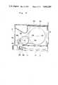
- FIG. 3is a side elevational view taken along the line III--III shown in FIG. 2;
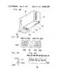
- FIG. 4is a perspective view of a drug dispensing cartridge disclosed in FIGS. 1 through 3, illustrating the connection between the cartridge and a portion of one of the shelves in the drug dispensing apparatus, with portions thereof broken away;
- FIG. 5is a side sectional view on an enlarged scale, taken along the line V--V in FIG. 4;
- FIG. 6is a cross sectional view on an enlarged scale, taken along the line VI--VI in FIG. 4;
- FIG. 7is a side view of the rotary plate of the cartridge showing one side thereof whereon the rotary plate is provided with a plurality of claw pieces;
- FIG. 8is a side view of the rotary plate showing the other side thereof whereon the rotary plate is provided with a plurality of ribs, an engaging state between the ribs and the stationary wall, and the drug doses detecting means;
- FIG. 9is a fragmentary cross sectional view of the drug dispensing cartridge on an enlarged scale, taken along the line IX--IX in FIG. 8;
- FIG. 10is a perspective view of a claw piece, on an enlarged scale, which is applied to the drug dispensing cartridge for the drug doses in table form;
- FIG. 11ais a portion of a side view similar to FIG. 8, showing a modification of the claw piece
- FIG. 11bis a perspective view of the claw piece, on an enlarged scale, illustrated in FIG. 11a;
- FIG. 12is a side view of the rotary plate of the second embodiment of the present invention, similar to FIG. 8;
- FIG. 13is a cross sectional view of the drug dispensing cartridge on an enlarged scale, taken along the line XIII--XIII in FIG. 12;
- FIG. 14is a perspective view of the claw piece, on an enlarged scale, which is applied to the drug dispensing cartridge for the drug doses in capsule form;
- FIG. 15is a diagram showing a state wherein the shielding plate of the elastic member intercepts the reed switch from the magnet;
- FIG. 16is a diagram similar to FIG. 15, showing a state wherein the reed switch faces the magnet;
- FIG. 17depicts two timing charts for the driving motor and the drug dose detecting signal showing an example wherein two kinds of the drug doses are discharged from the drug dispensing cartridges;
- FIG. 18is a perspective view of the cartridge with the lower case having a connector and a plurality of openings arranged in a circular state at the contact face thereof with one of the shelves in the apparatus;
- FIG. 19is a detailed view of the contact face, on an enlarged scale, illustrated in FIG. 18;
- FIG. 20is a detailed view of the pin, on an enlarged scale, engaging with one of the openings illustrated in FIG. 19;
- FIG. 21is a front view of one of the shelves accommodated in the apparatus, whereon the cartridge illustrated in FIG. 18 is placed;
- FIG. 22is a perspective view of the cartridge similar to FIG. 18, having a connector and a plurality of openings arranged in a matrix-like state on the lower case thereof;
- FIG. 23is a detailed view of the contact face on an enlarged scale, illustrated in FIG. 22;
- FIG. 24is a detailed view of the pin, on an enlarged scale, being inserted into one of the openings illustrated in FIG. 23;
- FIG. 25is a front view of one of the shelves in the apparatus, whereon the cartridge illustrated in FIG. 22 is placed;
- FIG. 26is a perspective view of the drug dispensing unit of the apparatus separated into two units.
- FIG. 27is a side sectional view of the drug dispensing unit of the apparatus joined in one unit.
- FIG. 1illustrates a drug dispensing apparatus 1 comprising a drug dispensing unit which is composed of a drug dispensing cartridges storing unit 1A and a drug doses packing unit 1B, and a control means 1C for dispensing and packing an individual drug dose or doses in compliance with input information.
- a drug dispensing apparatus 1comprising a drug dispensing unit which is composed of a drug dispensing cartridges storing unit 1A and a drug doses packing unit 1B, and a control means 1C for dispensing and packing an individual drug dose or doses in compliance with input information.
- FIGS. 2 and 3show the essential construction of the drug dispensing unit of the apparatus.
- the cartridges storing unit 1Awhich is open at both front and rear sides, accommodates a plurality of the drug dispensing cartridges 3 placed side by side and vertically on a plurality of corresponding shelves 2.
- Each shafthas a bottom plate and a back plate.
- the shelvesare arranged in two rows one behind the other.
- a hopper 5in connection with the drug passage 4 for collecting the drug doses from the cartridges 3 and a packing mechanism 6.
- the drug dosesare led into a packaging paper which is pulled out by a feed roller 13 from a roller 10 on which the packaging paper folded in two, is wound up, so that the drug dose or doses selectively discharged are pouched through heating by a heat seal device 14.
- FIG. 4shows a connection between the cartridge 3 and a portion of one of the shelves 2 in the drug dispensing unit.
- a groove 19is provided in a bottom surface 15 of each cartridge 3. The groove 19 engages with one of guide rails 16 formed on the shelf 2. Each cartridge 3 is properly placed in the drug dispensing unit through the engagement between the groove 19 and the guide rail 16.
- the cartridge 3is provided with a lower casing 22 which is in contact with a front face 2A of the shelf 2.
- the cartridge 3has a connector 23 as well as a plurality of openings 24 whereby the cartridge is electrically connected with the drug dispensing apparatus 1 and properly addressed thereto. Detailed explanations for the connector and the openings will be made later.
- FIGS. 5 and 6show the drug dispensing cartridge 3 with a cover 44.
- the cartridge 3has a drug storing portion 46 and a driving portion 47, both of which are partitioned by the parting strip 40.
- the drug dosesare replenished through an upper open side of the drug storing portion 46 which is normally closed by the cover 44.
- a driving motor 48is mounted on a supporting shaft 30 to turn in the same direction as a rotating direction of an output shaft 49 shown by an arrow a.
- An idler pulley 50has a rubber ring 45 on its peripheral portion. The rubber ring 45 of the idler pulley 50 is in contact with the output shaft 49.
- the idler puller 50is linked to a driven pulley 51 through a belt 52.
- double dotted chain linesshow a connector 28, lead wires 11 and a control circuit plate 17 in one of the shelves 2.
- a rotary plate 31is installed on a rotary shaft 34 of the driven pulley 51.
- the plate 31is supported by bearings 53.
- a guide wall 32protrudes toward the driven pulley 51
- ribs 37protrude toward the drug storing portion 46. As shown in FIG. 8, said ribs 37 are divided into four pieces at regular intervals.
- the ribs 37just inside of a stationary wall 39 when the rotary plate rotates
- the stationary wall 39is provided on the parting strip 40.
- a drug outlet 67is arranged at an appointed position of the stationary wall 39 so that each drug dose can be dispensed when an opening 36 between adjacent ribs 37 comes to a position facing the outlet 67.
- four sets of claw pieces 35are freely reciprocatable between a pair of guide plates 54, are arranged at regular intervals, i.e., at intervals of an angle of 90°, so as to reciprocate in a radial direction from the rotary shaft 34.
- the claw pieces 35are located on the face where the guide wall 32 is provided on the rotary plate 31.
- the guide wall 32is provided with four notches 33, each of which is opposed to a corresponding end of each claw piece 35.
- Each claw pieces 35has a shaft 55 and roller 56 rotatably supported on each shaft 55.
- a stationary plate 57Between the driven pulley 51 and the rotary plate 31 is arranged a stationary plate 57.
- a cam 61is rigidly mounted on stationary plate 57.
- An inner circumferential wall 58 of the cam 61has such a shape as shown by a double dotted chain line in FIGS. 7 and 8.
- the claw piece 35is urged to protrude in an outward direction from the rotary plate 31 through the notch 33 by means of a spring 65. Accordingly, the roller 56 moves along the inner circumferential wall 58 of the cam 61 according to the rotation of the rotary plate 31, while keeping in constant contact with the inner circumferential wall 58.
- the reciprocating motion of the claw piece 35is controlled in compliance with the shape of the inner circumferential wall 58 of a cam 61 having the first concave portion 59 and a second concave portion 60.
- the claw piece 35protrudes to the outward direction over the rotary plate 31 through the notch 33.
- Each of a plurality of engaging members 42reciprocating in a radial direction on the face of the rotary plate 31 where the ribs 37 are formed.
- the engaging member 42has one bent end mounted on the end of one of the claw pieces 35, with that end of the member 42 being bent toward the driven pulley 51.
- the other bent end of member 42forms a receiving portion 41 for the drug doses, with that other bent end being bent toward the drug storing portion 46 as shown in FIGS. 8-10.
- the cam 61, the spring 65 and the roller 56are so arranged respectively that, when the claw piece 35 protrudes in the outward direction over the rotary plate 31 through the notch 33, the receiving portion 41 for the drug doses also protrudes to a position where the ribs 37 are arranged so as to discharge the drug doses.
- control memberscomprise the spring 65 urging the claw piece 35 outwardly in a radial direction at all times, the roller 56 mounted on the claw piece 35 and the cam 61 having an inner circumferential wall 58 on and along which, the roller moves, while keeping in contact therewith.
- a guide plate 43is arranged along a travelling passage of the receiving portion 41 of the claw piece 35 upon reciprocation thereof.
- the parting strip 40is provided with a circular opening 38 having approximately the same radius as the distance between the receiving portion 41 and the shaft 34.
- the receiving portion 41closely approaches the shaft 34, the drug storing portion 46 leans through the opening 38 toward the face of the rotary plate 31 where the rotary plate 31 has the receiving portion 41 of the claw piece 35.
- An annular groove 63is formed in the space defined by the ribs 37 and the circumferential side 62 of the opening 38 due to the radius of the opening 38 than being smaller the distance between the rib 37 and the shaft 34. Since the bottom of the drug storing portion 46 is inclined towards the opening 38, the drug doses are led to the rotary plate 31 from the drug storing portion 46 through the opening 38 so as to be lined up along the groove 63 between the ribs 37 and the circumferential side 62 of the opening 38.
- FIG. 9is a cross sectional view, taken along the line IX--IX shown in FIG. 8, illustrating one of the drug doses in tablet form retained in the engaging member 42 and the guide plate 43 after the above mentioned line-up thereof along the groove 63.
- a single dotted chain line in FIG. 8shows an edge line of the inclined bottom of the drug storing portion 46, as indicated by C in FIG. 9.
- FIG. 10shows the engaging member 42 for the drug doses in tablet form made up of a plate having its opposite ends, one of which forms a receiving portion 41, bent at right angles thereto so as to extend in opposite directions away from each other.
- FIGS. 11a and 11bshow a modification of the engaging member 42A.
- an additional bent portion Eis arranged thereon so as to form an L-shaped receiving portion 41A for the purpose of deleting the guide plates 43 in FIG. 8.
- FIGS. 12, 13 and 14show another embodiment of the cartridge for the drug doses in capsule form, corresponding to FIGS. 8, 9 and 10, respectively.
- additional ribs 37A divided into four sectionsare provided inside of the ribs 37 on the rotary plate 31.
- the ribs 37Aprotrudge toward the drug storing portion 46 along with the ribs 37.
- the drug doses in capsule formare lined up in a space between both of the ribs 37 and 37A, so as to be retained on the engaging member 42B illustrated in FIG. 13.
- a single dotted chain line in FIG. 12shows an edge line of the inclined bottom of the drug storing portion 46, as indicated by D in FIG. 13.
- each drug dose in capsule formis retained on two of the faces F1 and F2, and the other two faces F3 and F4 are provided so as not to pinch one of the other drug doses between the engaging member 42A and the additional ribs 37A.
- an elastic member 70 supported from a stationary member outside of the rotary plate 31,is arranged at the drug outlet 67 to elastically close the outlet 67
- a reed switch 72 and a magnet 73are also arranged in the vicinity of the drug outlet 67.
- a shielding plate 71is disposed on the elastic member 70 and designed to extend between the reed switch 72 and the magnet 73 when the elastic member 70 closes the drug outlet 67.
- a detecting means for detecting each drug dose discharged from the drug outlet 67is composed of the elastic member 70 having the shielding plate 71, the reed switch 72 and the magnet 73 as described above.
- the driving motor 48, and the detecting meansare also electrically connected with the control circuit plate 17, upon connection of both of the connectors 23 and 28.
- the cartridge 3has the engaging member 42A with an L-shaped receiving portion 41A.
- a photoswitch 75may be used as the detecting means.
- the photoswitch 75comprises a light emitting element 76 and a light receiving element (not shown) arranged on the falling passage of the drug doses discharged from each cartridge 3. Since the elastic member 70 cannot be used because the shielding plate 71 thereof would be moved by each receiving portion 41A of the engaging member 42A and not by each drug dose discharged from each cartridge 3.
- the function of the drug dispensing cartridge 3, having the construction as described so farwill be explained hereinafter.
- the drug doses, supplied from the upper side of the drug dispensing cartridge 3,are not only stored in the drug storing portion 46, but led to the rotary plate 31 through the opening 38 so as to be lined up along the groove 63 formed between the ribs 37 and the circumferential side 62 of the opening 38.
- the idler pulley 50rotates in a direction to the direction shown by arrow a as well as to the driven pulley 51 while keeping in constant contact with the output shaft 49 at its circumferential edge directly.
- the rotary plate 31 driven by the driving motor 48rotates in a direction show by arrow A.
- the claw piece 35comes to a position P for dispensing a drug dose with the rotation of the rotary plate 31 the claw piece 35 protrudes outwardly over the rotary plate 31 through the corresponding notch 33, since the roller 56 is pressed to the second concave portion 60 of the cam 61 by means of the spring 65.
- the other claw pieces 35are drawn back towards the shaft 34 due to the reciprocating motion of each claw piece 35 being restricted by the cam 61 through roller 56.
- FIG. 8, corresponding to FIG. 7,illustrates the face where the rotary plate 31 is provided with the ribs 37.
- An arrow Bshows the rotating direction of the rotary plate 31.
- FIG. 8shows the drug doses lined up along the rib 37 situated at the lower portion of the rotary plate 31.
- a drug dose at the rearmost position in the rotating directionis retained by the guide plate 43 and the receiving portion 41 which is drawn back towards the shaft 34 with the rotation of the rotary plate 31.
- the drug doseis transferred to the drug takeout position P along the stationary wall 39.
- the claw piece 35 with the roller 56protrudes over the rotary plate 31 through the corresponding notch 33 to discharge the drug dose out of the drug outlet 67. Since the receiving portion 41 comes to approximately the same position as the rib 37, the drug dose retained thereon is led to the outside of the rotary plate 31 along the guide plate 43.
- the claw piece 35is drawn back toward the shaft 34 against the spring 65 under the restriction of the cam 61 so that it becomes possible to retain one of the other drug doses being lined up along the rib 37.
- one drug dose at a timecan be taken out every quarter turn of the rotary plate 31 since four sets of claw pieces 35 are provided.
- the drug dosesare steadily discharged out of the drug outlet 67 in such a manner that the drug doses, being lined up along the groove 63 formed between the ribs 37 and the circumferential side 62 of the opening 38, are dispensed one by one by the receiving portions 41 so as to be desirably retained therein.
- the shielding plate 71separates the reed switch 72 from the magnet. This results in the closure of the drug outlet 67 by the elastic member 70. Accordingly, since the magnetic flux from the magnet 73 to the reed switch 72 is shut off, the reed switch 72 is in an off state. As illustrated in FIG. 16, when the elastic member 70 is moved outwardly by the drug dose 66 being pushed out by the engaging member 42, the reed switch 72 and the magnet 73 come face to face with each other. Since the shielding plate 71 moves upwards, the reed switch 72 is turned on.
- the shielding plate 70closes the drug outlet 67 again the shielding plate 70 separates the reed switch 72 from the magnet 73 resulting in the reed switch 72 being turned off.
- the above mentioned changeover of the reed switch 72 from on to offis a drug detecting signal for controlling the drug dispensing apparatus 1.
- one of the drug dosesis dispensed by stopping the driving motor 48 at the time the drug detecting signal arises. Afterward the driving motor 48 is driven in compliance with drug discharging signals.
- the driving motor 48is stopped when the number of drug detecting signals have reached a predetermined number of the drug doses to be dispensing.
- FIG. 17shows two timing charts for the driving motor and the drug doses detecting signal.
- the exampleshows three drug doses dispensed from a drug dispensing cartridge A and another three drug doses dispensed from a cartridge B, for clearly explaining the above described process.
- each driving motor 48upon being ordered by the control means 1C starts rotating so as to stay in motion until one of the drug doses discharged from the cartridge is detected, and is driven again for discharging the next one of the drug doses after a brief stop thereof. With like processes being repeated, each driving motor 48 is completely stopped when three drug doses are discharged from each cartridge 3.
- FIGS. 18 through 21show the drug dispensing cartridge 3 with a first embodiment of the lower case 22 having a connector 23 and a plurality of openings 24 on the contact face between the cartridge 3 and one of the shelves 2 in the drug dispensing unit of the apparatus 1, as has been stated.
- a plurality of the openings 24are arranged in a circular state at regular intervals.
- a rotary shaft 26is mounted at the center of the circle.
- One end of shaft 26forms a lever 25 having at the other end a pin 27 for inserting in one of the openings 24. It is, therefore, possible to insert the pin 27 into any one of the openings 24 selectively by rotating the lever along the circle.
- a pair of such arrays of 16 openings 24 and a pin 27can produce 256 (16 ⁇ 16) combinations.
- the front surface 2A of one of the shelves 2is provided with a plurality of groups of a connector 28 and a pair of openings. Each opening engaging with one of the pins 27.
- the positions of the openingscorrespond to those of a pair of pins 27 arranged on the drug dispensing cartridge 3 to be placed thereon.
- a pair of openings 24 of the cartridge 3, into which a pair of pins 27 are insertedare determined in compliance with the kind of drug doses to be stored therein.
- a pair of engaging openings 29are formed on the front surface 2A of the shelf 2 where the cartridge 3 is placed, while facing a pair of the openings 24 determined as mentioned above. Accordingly, when the corresponding cartridge 3 is placed at the proper position on one of the shelves 2 in the apparatus 1, the cartridge 3 is electrically connected with the apparatus 1 through the connectors 23 and 28, since a pair of pins 27 engage with a pair of engaging openings 29 formed on the front surface 2A of one of the shelves 2.
- FIGS. 22 through 25illustrate the drug dispensing cartridge 3 with a second embodiment of the lower case 22 which comprises a connector 23 and a pair of number setting portions 20A and 20B having a plurality of openings arrayed in a matrix-like state each on the contact surface between the cartridge 3 and one of the shelves 2 in the drug dispensing unit.
- a pair of the number setting portions 20A and 20B each having 16 openings 24A and a pin 27Acan also produce 256 (16 ⁇ 16) combinations.
- the number setting portion 20Acomprises 8 openings 24A in 2 upper lines. Each correspond to one of 8 rows of front side shelves 2, and 8 openings 24A of 2 lower lines, each correspond to one of 8 rows of rear side shelves 2, for setting the number of each shelf 2.
- the number setting portion 20Bcomprises 16 openings 24A, each corresponding to one of 16 cartridges 3 to be placed on one of the shelves 2, for setting the number of each position whereon each cartridge 3 is placed.
- each of a pair of pins 27Ais inserted into each one opening 24A of a pair of the number setting portions 20A and 20B for indicating both the shelf number and the position number of the cartridge 3 according to the position of the cartridge 3 to be placed.
- the cartridge 3can be shifted to another position by replacing a pin or pins 27A.
- a pin 27Ais inserted into an opening 24A on the number setting portion 20A which indicates 2 as a shelf number and another pin 27A is also inserted into another opening 24A on the number setting portion 20B which indicates 3 as a position number of the cartridge 3.
- FIG. 25at the front surface 2A of one of the shelves are provided a plurality of groups comprising a connector 28 and a pair of engaging openings 29A which engage with a pair of pins 27A and are arranged according to both the shelf number from the top and the position number from the left. That is, a pair of the engaging openings 29A are formed so as to face a pair of openings 24A whereinto a pair of pins 27A are inserted on the number setting portions 20A and 20B of the corresponding drug dispensing cartridge 3.
- the drug doseis not erroneously dispensed from the cartridge 3 placed improperly on one of the shelves 2.
- An operatorcan find out about an incomplete engagement between the pins 27A and the engaging openings 29A in advance, in the case already described, wherein the cartridge 3 has a lower case 22 with a plurality of openings 24 arranged in a circular state at regular intervals.
- an improper placement of the cartridge 3 on one of the shelves 2can be previously prevented through the confirmation of the pin positions on both number setting portions 20A and 20B of the cartridge 3.
- FIGS. 26 and 27show an example wherein the dispensing unit is divided into two units. That is, the first drug dispensing unit 1M and the second drug dispensing unit 1N along the drug doses falling passage 4 is arranged vertically therein.
- both of the above described units 1M and 1Nare freely openable within the range defined by a stopper 87 with the second drug dispensing unit 1N as a turning side. Both units have a roller 89 for rotation under a bottom plate 88 thereof, a handle 90 and a plurality of locking devices 91.
- a parting curtain 93is provided in the drug doses falling passage 4 so that each drug dose discharged from one of the cartridges 3 falls along the parting curtain 93 without collision thereof against the cartridges 3.
- the drug dispensing cartridges storing unit 1A and the drug doses packing unit 1Bare formed in one united body in each of the first and second drug dispensing units 1M and 1N respectively, with the hopper 5 and the packing mechanism 6 being accommodated in the first unit 1M, such a modification can be adopted that the drug dispensing unit comprises the cartridges storing unit 1A separable into two units and the drug doses packing unit 1B united in one body.
- first and second drug dispensing units 1M and 1Ncan be separated not only in the turning style as described above, but also in a sliding style wherein both units 1M and 1N are slidingly separated in a parallel or perpendicular direction with respect to a separating face between the two, or in a lifting up style wherein both units 1M and 1N, hingedly connected at an upper or a lower side thereof are pivotally separated.
- the drug dispensing cartridges storing unit 1Ahas a plurality of shelves 2 arranged in two rows, one behind the other, and the drug doses falling passage 4 formed between the front and rear rows of the shelves, but the cartridges storing unit 1A may be so designed so that a plurality of shelves 2 are vertically arranged in only one row therein, with the front side thereof being opened and the drug doses falling passage 4 being formed between the shelves 2 and a rear plate of the cartridges storing unit 1A.
Landscapes
- Physics & Mathematics (AREA)
- General Physics & Mathematics (AREA)
- Medical Preparation Storing Or Oral Administration Devices (AREA)
Abstract
Description
Claims (12)
Applications Claiming Priority (5)
| Application Number | Priority Date | Filing Date | Title |
|---|---|---|---|
| JP8364685UJPS61200306U (en) | 1985-06-03 | 1985-06-03 | |
| JP60-83646[U] | 1985-06-03 | ||
| JP60-92673[U]JPX | 1985-06-19 | ||
| JP9267385UJPH0449044Y2 (en) | 1985-06-19 | 1985-06-19 | |
| JP1985092674UJPH0441048Y2 (en) | 1985-06-19 | 1985-06-19 |
Publications (1)
| Publication Number | Publication Date |
|---|---|
| US4664289Atrue US4664289A (en) | 1987-05-12 |
Family
ID=27304286
Family Applications (1)
| Application Number | Title | Priority Date | Filing Date |
|---|---|---|---|
| US06/778,638Expired - LifetimeUS4664289A (en) | 1985-06-03 | 1985-09-20 | Drug dispensing apparatus |
Country Status (1)
| Country | Link |
|---|---|
| US (1) | US4664289A (en) |
Cited By (118)
| Publication number | Priority date | Publication date | Assignee | Title |
|---|---|---|---|---|
| US4785969A (en)* | 1986-11-10 | 1988-11-22 | Pyxis Corporation | Medication dispensing system |
| US4823982A (en)* | 1985-04-11 | 1989-04-25 | Medical Microsystems, Inc. | Multiple cartridge dispensing system |
| US4967928A (en)* | 1988-06-09 | 1990-11-06 | Carter Cheryl L | Inventory control including individual patient listing and medical chart record for medication cart |
| EP0412806A1 (en)* | 1989-08-10 | 1991-02-13 | Sanyo Electric Co., Ltd | Drug packing apparatus |
| US5047948A (en)* | 1989-04-25 | 1991-09-10 | Turner Joseph D | Medication dispensing system |
| US5208762A (en)* | 1990-12-06 | 1993-05-04 | Baxter International Inc. | Automated prescription vial filling system |
| US5292029A (en)* | 1989-11-08 | 1994-03-08 | Pearson Walter G | Patient medication dispensing and associated record |
| WO1994012393A1 (en)* | 1992-12-01 | 1994-06-09 | Baxter International Inc. | Tablet accumulator for automated vial filling system |
| US5405048A (en)* | 1993-06-22 | 1995-04-11 | Kvm Technologies, Inc. | Vacuum operated medicine dispenser |
| US5490610A (en)* | 1994-03-07 | 1996-02-13 | Pearson; Walter G. | Semi-automated medication dispenser |
| US5509573A (en)* | 1994-03-23 | 1996-04-23 | Campoli; William J. | Aseptic dispensing system |
| US5671592A (en)* | 1994-10-21 | 1997-09-30 | Yuyama Mfg. Co., Ltd. | Medicine packing apparatus |
| US5720154A (en)* | 1994-05-27 | 1998-02-24 | Medco Containment Services, Inc. | Enhanced drug dispensing system |
| USRE35743E (en)* | 1988-09-12 | 1998-03-17 | Pearson Ventures, L.L.C. | Patient medication dispensing and associated record keeping system |
| US5771657A (en)* | 1996-05-07 | 1998-06-30 | Merck Medco Managed Care, Inc. | Automatic prescription filling, sorting and packaging system |
| US5790409A (en)* | 1993-01-25 | 1998-08-04 | Medselect Systems, Inc. | Inventory monitoring and dispensing system for medical items |
| US5810080A (en)* | 1995-11-10 | 1998-09-22 | Institut Francais Du Petrole | Device for exploring an underground formation crossed by a horizontal well comprising several anchorable sondes |
| US5827180A (en)* | 1994-11-07 | 1998-10-27 | Lifemasters Supported Selfcare | Method and apparatus for a personal health network |
| US5838575A (en)* | 1995-12-14 | 1998-11-17 | Rx Excell Inc. | System for dispensing drugs |
| US5901876A (en)* | 1996-01-26 | 1999-05-11 | Kabushiki Kaisha Yuyama Seisakusho | Drug storage/discharge apparatus |
| US6032155A (en)* | 1997-04-14 | 2000-02-29 | De La Huerga; Carlos | System and apparatus for administering prescribed medication to a patient |
| US6079592A (en)* | 1998-08-04 | 2000-06-27 | Alcoa Closure Systems International | Apparatus for automatically creating blended stream of promotional articles |
| US6082578A (en)* | 1996-11-28 | 2000-07-04 | Japan Tobacco Inc. | Vending machine for packaged commodities |
| US6108588A (en)* | 1993-01-25 | 2000-08-22 | Diebold, Incorporated | Restocking method for medical item dispensing system |
| EP0945117A3 (en)* | 1998-03-26 | 2000-10-18 | SANYO ELECTRIC Co., Ltd. | Drug dispensing apparatus |
| US6138865A (en)* | 1995-12-29 | 2000-10-31 | Gilmore; Janice F. | Automatic medicament dispenser system |
| US6170230B1 (en) | 1998-12-04 | 2001-01-09 | Automed Technologies, Inc. | Medication collecting system |
| US6259654B1 (en) | 1997-03-28 | 2001-07-10 | Telaric, L.L.C. | Multi-vial medication organizer and dispenser |
| US6256967B1 (en) | 1998-08-27 | 2001-07-10 | Automed Technologies, Inc. | Integrated automated drug dispenser method and apparatus |
| US20010028308A1 (en)* | 1997-03-28 | 2001-10-11 | Carlos De La Huerga | Interactive medication container |
| US20020038392A1 (en)* | 1999-10-22 | 2002-03-28 | Carlos De La Huerga | Method and apparatus for controlling an infusion pump or the like |
| US6367232B2 (en)* | 2000-04-24 | 2002-04-09 | Jv Medi Co., Ltd. | Tablet cassette installation-error preventing system for automatic tablet supplying and packaging apparatus |
| US6370841B1 (en) | 1999-12-03 | 2002-04-16 | Automed Technologies, Inc. | Automated method for dispensing bulk medications with a machine-readable code |
| USRE37829E1 (en)* | 1990-12-06 | 2002-09-03 | Automed Technologies, Inc. | Automated prescription vial filling system |
| US6471090B1 (en)* | 1998-09-29 | 2002-10-29 | Sanyo Electric Co., Ltd. | Medicine supply apparatus |
| US6529446B1 (en) | 1996-12-20 | 2003-03-04 | Telaric L.L.C. | Interactive medication container |
| US6574861B1 (en) | 2001-04-11 | 2003-06-10 | Applied Micro Circuits Corporation | System and method for solder ball rework |
| US6585132B2 (en)* | 2001-09-24 | 2003-07-01 | Jun H. Kim | Tablet cassette assembly with slider cabinets for automatic tablet dispensing and packaging system |
| US6611733B1 (en) | 1996-12-20 | 2003-08-26 | Carlos De La Huerga | Interactive medication dispensing machine |
| US20030216831A1 (en)* | 1999-09-22 | 2003-11-20 | Telepharmacy Solutions, Inc. | Systems and methods for dispensing medical products |
| US20030230590A1 (en)* | 1998-06-25 | 2003-12-18 | Gilmore Janice F. | Automatic medicament dispenser system |
| US6690998B1 (en)* | 1999-11-01 | 2004-02-10 | Yuyama Mfg. Co., Ltd. | Medication packing apparatus |
| US20040158507A1 (en)* | 2002-12-06 | 2004-08-12 | Meek Robert B. | Inventory management and replenishment system |
| US20040182044A1 (en)* | 2003-03-19 | 2004-09-23 | Kim Jun Ho | Automatic tablet dispensing and packaging system |
| US20040188524A1 (en)* | 2001-11-30 | 2004-09-30 | Richard Lunak | Method of initiating and recording a pick with a hand held device |
| US20040210341A1 (en)* | 1999-09-22 | 2004-10-21 | Telepharmacy Solutions, Inc. | Systems and methods for dispensing medical products |
| US20040260424A1 (en)* | 2002-07-26 | 2004-12-23 | Mahar Michael L. | Prescription order packaging system and method |
| US20050065645A1 (en)* | 1995-10-18 | 2005-03-24 | Telepharmacy Solutions, Incorporated | Method for controlling a drug dispensing system |
| EP1489000A4 (en)* | 2002-02-20 | 2005-05-11 | Sanyo Electric Co | Chemical feeding device |
| US20050098569A1 (en)* | 2002-05-14 | 2005-05-12 | Williams Jeffrey P. | System and method for dispensing prescriptions |
| US20050113969A1 (en)* | 2003-11-26 | 2005-05-26 | Mckesson Automation Inc. | Integrated suite of medical tools |
| US20050178778A1 (en)* | 2003-12-19 | 2005-08-18 | Berg Michael D. | System and method for monitored delivery of products |
| EP1604631A1 (en)* | 2004-06-10 | 2005-12-14 | JVM Co., Ltd. | Tablet automatic packaging machine |
| US20060006190A1 (en)* | 2004-07-07 | 2006-01-12 | Janet Jason A | Automated article dispensation mechanism |
| US20060025884A1 (en)* | 2004-05-20 | 2006-02-02 | Claus Henkel | Systems and methods of automated tablet dispensing, prescription filling, and packaging |
| US20060058725A1 (en)* | 2004-09-13 | 2006-03-16 | Michael Handfield | Smart tray for dispensing medicaments |
| US20060118573A1 (en)* | 2004-11-03 | 2006-06-08 | Ganz Brian L | Automated small item dispense module |
| US20060120751A1 (en)* | 2004-12-03 | 2006-06-08 | Mcvicker Henry J | Apparatus and method for obtaining an image of an arcuate surface |
| US7061831B2 (en) | 1997-03-28 | 2006-06-13 | Carlos De La Huerga | Product labeling method and apparatus |
| US20060175942A1 (en)* | 2002-12-06 | 2006-08-10 | Mckesson Automation Inc. | High capacity drawer with mechanical indicator for a dispensing device |
| EP1700592A1 (en)* | 2005-03-10 | 2006-09-13 | JVM Co., Ltd. | Tablet automatic packaging machine and method for automatically recognizing cassettes coupled to cartridge thereof |
| US20060241807A1 (en)* | 2005-04-21 | 2006-10-26 | Matt Daniels | Devices useful in system and method for dispensing prescriptions |
| US20060237093A1 (en)* | 2001-10-11 | 2006-10-26 | Kirby Lester, Llc | Method and System for High-Speed Tablet Counting and Dispensing |
| US20060292492A1 (en)* | 2005-06-27 | 2006-12-28 | Nec Corporation | Optical information recording medium and optical information reproducing apparatus |
| US7185476B1 (en) | 1999-05-11 | 2007-03-06 | Mts, Medication Technologies, Inc. | Automated solid pharmaceutical product packaging machine |
| US20070062156A1 (en)* | 2005-08-25 | 2007-03-22 | Kim Jun H | Automatic medicine packing system |
| US20070084150A1 (en)* | 2000-11-01 | 2007-04-19 | Medical Technology Systems, Inc. | Automated solid pharmaceutical product packaging machine |
| US7216802B1 (en) | 1997-10-21 | 2007-05-15 | Carlos De La Huerga | Method and apparatus for verifying information |
| US20070296598A1 (en)* | 2006-06-21 | 2007-12-27 | Jun Ho Kim | Apparatus for identifying support tray data and method thereof |
| US7313898B1 (en) | 2003-08-29 | 2008-01-01 | Express Scripts, Inc. | Container carrying system and method for use in an automated filling process |
| US20080017658A1 (en)* | 2006-07-19 | 2008-01-24 | Javelin Pharmaceuticals, Inc. | Dispensing device |
| US20080056556A1 (en)* | 2003-01-30 | 2008-03-06 | Eller Charles E | Prescription bottle imaging system and method |
| US20080071648A1 (en)* | 2006-09-20 | 2008-03-20 | Jun Ho Kim | Integrated control system and method for automatic medicine packaging apparatuses |
| US7349858B1 (en)* | 1994-12-16 | 2008-03-25 | Automed Technologies, Inc. | Method of dispensing and tracking the giving of medical items to patients |
| US20080077274A1 (en)* | 2006-09-22 | 2008-03-27 | Jun Ho Kim | Medicine storage cabinet |
| US20080099499A1 (en)* | 2006-11-01 | 2008-05-01 | Jun Ho Kim | Cassette device for automatic medicine packaging apparatus |
| US20080104929A1 (en)* | 2006-11-02 | 2008-05-08 | Jun Ho Kim | Apparatus and method for preventing irregular packaging for automatic medicine packing machine |
| US20080114818A1 (en)* | 2006-11-13 | 2008-05-15 | Jun Ho Kim | Method and apparatus for backing up power failure for automatic medicine packing machine |
| US20080110555A1 (en)* | 2006-11-14 | 2008-05-15 | Steve Bouchelle | Device and method for labeling vials useful in system for dispensing prescriptions |
| US20080110921A1 (en)* | 2006-11-14 | 2008-05-15 | Dumond Jody | Device for dispensing vials useful in system and method for dispensing prescriptions |
| US20080149657A1 (en)* | 2006-12-22 | 2008-06-26 | Jun Ho Kim | Method and apparatus for inspecting manual dispensing tray of automatic medicine packaging machine |
| US20080149522A1 (en)* | 2006-12-22 | 2008-06-26 | Jun Ho Kim | Division-packaging method and apparatus for automatic medicine packaging machine |
| US20080169302A1 (en)* | 2007-01-17 | 2008-07-17 | Young Demetris P | Device for dispensing caps useful in system and method for dispensing prescriptions |
| US20080172987A1 (en)* | 2007-01-17 | 2008-07-24 | John Richard Sink | Devices for Capping Vials Useful in System and Method for Dispensing Prescriptions |
| US20080173663A1 (en)* | 2007-01-22 | 2008-07-24 | Moran Joseph C | Cap Dispensing Devices Useful in System and Method for Dispensing Prescriptions |
| US20080245810A1 (en)* | 2007-04-05 | 2008-10-09 | Parata Systems, Llc | Methods and apparatus for dispensing solid pharmaceutical articles |
| US20080270178A1 (en)* | 2007-04-30 | 2008-10-30 | Mckesson Specialty Distribution Llc | Inventory Management System For A Medical Service Provider |
| US7451583B2 (en) | 2006-12-22 | 2008-11-18 | Jvm Co., Ltd. | Automatic medicine packaging machine with door lock unit |
| US20080283543A1 (en)* | 2007-05-18 | 2008-11-20 | Parata Systems, Llc | Methods and apparatus for dispensing solid pharmaceutical articles |
| US20080283549A1 (en)* | 2007-05-18 | 2008-11-20 | Parata Systems, Llc | Methods and apparatus for dispensing solid pharmaceutical articles |
| US20080283734A1 (en)* | 2007-05-18 | 2008-11-20 | Parata Systems, Llc | Methods and apparatus for dispensing solid articles |
| US7467093B1 (en)* | 1994-12-16 | 2008-12-16 | Automed Technologies, Inc | Method of tracking and despensing medical items to patients through self service delivery system |
| US20090043421A1 (en)* | 2007-08-10 | 2009-02-12 | Parata Systems, Llc | System and method for dispensing prescriptions |
| US20090173748A1 (en)* | 2008-01-09 | 2009-07-09 | Parata Systems, Llc. | Methods and apparatus for dispensing solid articles |
| US20090173745A1 (en)* | 2008-01-04 | 2009-07-09 | Parata Systems, Llc | System and Method for Dispensing Prescriptions |
| US20090179041A1 (en)* | 2008-01-16 | 2009-07-16 | Young Demetris P | Devices for Dispensing Objects Useful in System and Method for Dispensing |
| US20090294464A1 (en)* | 2008-05-30 | 2009-12-03 | Parata Systems, Llc | Methods and apparatus for dispensing solid articles |
| DE102009017869B3 (en)* | 2009-04-17 | 2010-05-20 | Sim Automation Gmbh & Co. Kg | Method for individual arrangement of tablets used as medicines or food supplement by patient in e.g. pharmacies, involves loosely holding tablets in storage containers, and supplying and packing tablets in portions to packing device |
| US7751932B1 (en) | 1993-01-25 | 2010-07-06 | Automed Technologies, Inc. | Method for tracking and dispensing medical items |
| US20100263325A1 (en)* | 2002-09-27 | 2010-10-21 | Sanyo Electric Co., Ltd. | Medicine feeding device |
| US20100307108A1 (en)* | 2007-01-17 | 2010-12-09 | John Richard Sink | Devices for Capping Vials Useful in System and Method for Dispensing Prescriptions |
| US20100332021A1 (en)* | 2009-06-25 | 2010-12-30 | Rivenbark Jr James Robert | Apparatus For Dispensing And Detecting Solid Pharmaceutical Articles And Related Methods of Operation |
| US20110178634A1 (en)* | 2008-11-21 | 2011-07-21 | Yuyama Mfg. Co., Ltd. | Tablet dispenser |
| US20110233840A1 (en)* | 2008-09-30 | 2011-09-29 | John Richard Sink | Devices for Capping Vials Useful in System and Method for Dispensing Prescriptions |
| US20120324829A1 (en)* | 2010-03-05 | 2012-12-27 | Tosho Inc. | Medicine dispensing apparatus |
| US8413410B2 (en) | 2010-04-30 | 2013-04-09 | Parata Systems, Llc | Devices for capping vials useful in system and method for dispensing prescriptions |
| US20140117038A1 (en)* | 2012-11-01 | 2014-05-01 | Jvm Co., Ltd. | Drug dispensing box and cartridge having mutually coupled structure |
| US8823770B2 (en) | 2012-01-26 | 2014-09-02 | Meditory Llc | Device and methods for fabricating a two-dimensional image of a three-dimensional object |
| KR101468880B1 (en)* | 2013-03-11 | 2014-12-05 | 주식회사 인포피아 | cartridge for drug dispensing apparatus being easily connected |
| US8963710B2 (en) | 2013-03-05 | 2015-02-24 | Jiandong Huang | Systems and apparatus for container conversion |
| US20150203227A1 (en)* | 2012-08-31 | 2015-07-23 | Carefusion Switzerland 317 Sarl | Apparatus for packaging dosed quantities of solid drug portions |
| US9443370B2 (en) | 2012-03-26 | 2016-09-13 | Omnicare, Inc. | Method and apparatus for onsite distribution of medications and medical supplies |
| US20160332753A1 (en)* | 2015-05-13 | 2016-11-17 | Carefusion Germany 326 Gmbh | Device for packaging medication portions |
| US9790017B2 (en) | 2008-11-21 | 2017-10-17 | Yuyama Mfg. Co., Ltd. | Tablet feeder and pharmacy system |
| CN108289791A (en)* | 2015-11-25 | 2018-07-17 | 株式会社高园科技 | Medicine feeding apparatus |
| GB2569235A (en)* | 2017-11-23 | 2019-06-12 | Anthony Frost Robert | Tablet dispenser |
| US20230181426A1 (en)* | 2020-10-27 | 2023-06-15 | Phc Holdings Corporation | Chemical agent supply device and chemical agent supply method |
| US12036185B2 (en) | 2021-07-19 | 2024-07-16 | Optum, Inc. | System and method to count pills |
Citations (6)
| Publication number | Priority date | Publication date | Assignee | Title |
|---|---|---|---|---|
| US3079475A (en)* | 1959-06-09 | 1963-02-26 | Roy W Rumble | Electrical plug |
| US3382475A (en)* | 1966-02-03 | 1968-05-07 | Army Usa | Cable connector adaptor |
| US4018358A (en)* | 1975-09-18 | 1977-04-19 | Pharmaceutical Innovators, Ltd. | Cassette pill storing, dispensing and counting machine |
| US4047635A (en)* | 1975-08-28 | 1977-09-13 | Bennett Jr Arthur A | Article dispensing apparatus for selectively dispensing articles |
| US4125309A (en)* | 1977-06-22 | 1978-11-14 | Amp Incorporated | Miniature pin board assembly |
| US4460811A (en)* | 1982-11-30 | 1984-07-17 | Murr Paul G | Combination switching connector |
- 1985
- 1985-09-20USUS06/778,638patent/US4664289A/ennot_activeExpired - Lifetime
Patent Citations (6)
| Publication number | Priority date | Publication date | Assignee | Title |
|---|---|---|---|---|
| US3079475A (en)* | 1959-06-09 | 1963-02-26 | Roy W Rumble | Electrical plug |
| US3382475A (en)* | 1966-02-03 | 1968-05-07 | Army Usa | Cable connector adaptor |
| US4047635A (en)* | 1975-08-28 | 1977-09-13 | Bennett Jr Arthur A | Article dispensing apparatus for selectively dispensing articles |
| US4018358A (en)* | 1975-09-18 | 1977-04-19 | Pharmaceutical Innovators, Ltd. | Cassette pill storing, dispensing and counting machine |
| US4125309A (en)* | 1977-06-22 | 1978-11-14 | Amp Incorporated | Miniature pin board assembly |
| US4460811A (en)* | 1982-11-30 | 1984-07-17 | Murr Paul G | Combination switching connector |
Cited By (296)
| Publication number | Priority date | Publication date | Assignee | Title |
|---|---|---|---|---|
| US4823982A (en)* | 1985-04-11 | 1989-04-25 | Medical Microsystems, Inc. | Multiple cartridge dispensing system |
| US4785969A (en)* | 1986-11-10 | 1988-11-22 | Pyxis Corporation | Medication dispensing system |
| US4967928A (en)* | 1988-06-09 | 1990-11-06 | Carter Cheryl L | Inventory control including individual patient listing and medical chart record for medication cart |
| USRE35743E (en)* | 1988-09-12 | 1998-03-17 | Pearson Ventures, L.L.C. | Patient medication dispensing and associated record keeping system |
| US5562232A (en)* | 1988-09-12 | 1996-10-08 | Pearson; Walter G. | Semi-automated medication dispenser |
| US5047948A (en)* | 1989-04-25 | 1991-09-10 | Turner Joseph D | Medication dispensing system |
| EP0412806A1 (en)* | 1989-08-10 | 1991-02-13 | Sanyo Electric Co., Ltd | Drug packing apparatus |
| US5292029A (en)* | 1989-11-08 | 1994-03-08 | Pearson Walter G | Patient medication dispensing and associated record |
| US5208762A (en)* | 1990-12-06 | 1993-05-04 | Baxter International Inc. | Automated prescription vial filling system |
| USRE37829E1 (en)* | 1990-12-06 | 2002-09-03 | Automed Technologies, Inc. | Automated prescription vial filling system |
| WO1994012393A1 (en)* | 1992-12-01 | 1994-06-09 | Baxter International Inc. | Tablet accumulator for automated vial filling system |
| US5348061A (en)* | 1992-12-01 | 1994-09-20 | Baxter International Inc. | Tablet accumulator for an automated prescription vial filling system |
| US7751932B1 (en) | 1993-01-25 | 2010-07-06 | Automed Technologies, Inc. | Method for tracking and dispensing medical items |
| US6108588A (en)* | 1993-01-25 | 2000-08-22 | Diebold, Incorporated | Restocking method for medical item dispensing system |
| US6163737A (en)* | 1993-01-25 | 2000-12-19 | Diebold, Incorporated | Medical item dispensing apparatus |
| US5790409A (en)* | 1993-01-25 | 1998-08-04 | Medselect Systems, Inc. | Inventory monitoring and dispensing system for medical items |
| US5405048A (en)* | 1993-06-22 | 1995-04-11 | Kvm Technologies, Inc. | Vacuum operated medicine dispenser |
| US5490610A (en)* | 1994-03-07 | 1996-02-13 | Pearson; Walter G. | Semi-automated medication dispenser |
| US5649641A (en)* | 1994-03-23 | 1997-07-22 | Campoli; William J. | Cartridge for a dispensing system |
| US5509573A (en)* | 1994-03-23 | 1996-04-23 | Campoli; William J. | Aseptic dispensing system |
| US5720154A (en)* | 1994-05-27 | 1998-02-24 | Medco Containment Services, Inc. | Enhanced drug dispensing system |
| USRE40453E1 (en)* | 1994-05-27 | 2008-08-12 | Medco Health Solutions, Inc. | Enhanced drug dispensing system |
| US5671592A (en)* | 1994-10-21 | 1997-09-30 | Yuyama Mfg. Co., Ltd. | Medicine packing apparatus |
| US5827180A (en)* | 1994-11-07 | 1998-10-27 | Lifemasters Supported Selfcare | Method and apparatus for a personal health network |
| US7467093B1 (en)* | 1994-12-16 | 2008-12-16 | Automed Technologies, Inc | Method of tracking and despensing medical items to patients through self service delivery system |
| US7349858B1 (en)* | 1994-12-16 | 2008-03-25 | Automed Technologies, Inc. | Method of dispensing and tracking the giving of medical items to patients |
| US20050065645A1 (en)* | 1995-10-18 | 2005-03-24 | Telepharmacy Solutions, Incorporated | Method for controlling a drug dispensing system |
| US7151982B2 (en) | 1995-10-18 | 2006-12-19 | Telepharmacy Solutions, Inc. | Pharmaceutical dispensing system |
| US5810080A (en)* | 1995-11-10 | 1998-09-22 | Institut Francais Du Petrole | Device for exploring an underground formation crossed by a horizontal well comprising several anchorable sondes |
| US5838575A (en)* | 1995-12-14 | 1998-11-17 | Rx Excell Inc. | System for dispensing drugs |
| US6138865A (en)* | 1995-12-29 | 2000-10-31 | Gilmore; Janice F. | Automatic medicament dispenser system |
| US5901876A (en)* | 1996-01-26 | 1999-05-11 | Kabushiki Kaisha Yuyama Seisakusho | Drug storage/discharge apparatus |
| US6012602A (en)* | 1996-01-26 | 2000-01-11 | Kabushiki Kaisha Yuyama Seisakusho | Drug storage/discharge apparatus |
| USRE40510E1 (en) | 1996-05-07 | 2008-09-23 | Medco Health Solutions, Inc. | Automatic prescription filling, sorting and packaging system |
| US5771657A (en)* | 1996-05-07 | 1998-06-30 | Merck Medco Managed Care, Inc. | Automatic prescription filling, sorting and packaging system |
| USRE42766E1 (en) | 1996-05-07 | 2011-10-04 | Medco Health Solutions, Inc. | Automatic prescription filling, sorting and packaging system |
| USRE42730E1 (en) | 1996-05-07 | 2011-09-27 | Medco Health Solutions, Inc. | Automatic prescription filling, sorting and packaging system |
| USRE42937E1 (en) | 1996-05-07 | 2011-11-22 | Medco Health Solutions, Inc. | Automatic prescription filling, sorting and packaging system |
| US6082578A (en)* | 1996-11-28 | 2000-07-04 | Japan Tobacco Inc. | Vending machine for packaged commodities |
| US6611733B1 (en) | 1996-12-20 | 2003-08-26 | Carlos De La Huerga | Interactive medication dispensing machine |
| US7715277B2 (en) | 1996-12-20 | 2010-05-11 | Carlos De La Huerga | Interactive medication container |
| US6529446B1 (en) | 1996-12-20 | 2003-03-04 | Telaric L.L.C. | Interactive medication container |
| US20030099158A1 (en)* | 1996-12-20 | 2003-05-29 | Carlos De La Huerga | Interactive medication container |
| US6259654B1 (en) | 1997-03-28 | 2001-07-10 | Telaric, L.L.C. | Multi-vial medication organizer and dispenser |
| US7061831B2 (en) | 1997-03-28 | 2006-06-13 | Carlos De La Huerga | Product labeling method and apparatus |
| US7978564B2 (en) | 1997-03-28 | 2011-07-12 | Carlos De La Huerga | Interactive medication container |
| US20010028308A1 (en)* | 1997-03-28 | 2001-10-11 | Carlos De La Huerga | Interactive medication container |
| US6032155A (en)* | 1997-04-14 | 2000-02-29 | De La Huerga; Carlos | System and apparatus for administering prescribed medication to a patient |
| US7216802B1 (en) | 1997-10-21 | 2007-05-15 | Carlos De La Huerga | Method and apparatus for verifying information |
| EP0945117A3 (en)* | 1998-03-26 | 2000-10-18 | SANYO ELECTRIC Co., Ltd. | Drug dispensing apparatus |
| US20030230590A1 (en)* | 1998-06-25 | 2003-12-18 | Gilmore Janice F. | Automatic medicament dispenser system |
| US20050209733A1 (en)* | 1998-06-25 | 2005-09-22 | Gilmore Janice F | Automatic medicament dispenser system |
| US7344047B2 (en) | 1998-06-25 | 2008-03-18 | Handy-I Med Solutions, Llc | Automatic medicament dispenser system |
| US6079592A (en)* | 1998-08-04 | 2000-06-27 | Alcoa Closure Systems International | Apparatus for automatically creating blended stream of promotional articles |
| US6742671B2 (en) | 1998-08-27 | 2004-06-01 | Automed Technologies, Inc. | Integrated automated drug dispenser method and apparatus |
| US6449927B2 (en) | 1998-08-27 | 2002-09-17 | Automed Technologies, Inc. | Integrated automated drug dispenser method and apparatus |
| US6256967B1 (en) | 1998-08-27 | 2001-07-10 | Automed Technologies, Inc. | Integrated automated drug dispenser method and apparatus |
| US6471090B1 (en)* | 1998-09-29 | 2002-10-29 | Sanyo Electric Co., Ltd. | Medicine supply apparatus |
| US6625952B1 (en) | 1998-12-04 | 2003-09-30 | Automed Technologies, Inc. | Medication collecting system |
| US6170230B1 (en) | 1998-12-04 | 2001-01-09 | Automed Technologies, Inc. | Medication collecting system |
| US20070125046A1 (en)* | 1999-05-11 | 2007-06-07 | Mts Medication Technologies, Inc. | Automated Solid Pharmaceutical Product Packaging Machine |
| US10392140B2 (en) | 1999-05-11 | 2019-08-27 | Mts Medication Technologies, Inc. | Automated solid pharmaceutical product packaging machine |
| US7185476B1 (en) | 1999-05-11 | 2007-03-06 | Mts, Medication Technologies, Inc. | Automated solid pharmaceutical product packaging machine |
| US20100230005A1 (en)* | 1999-05-11 | 2010-09-16 | Mts Medication Technologies, Inc. | Automated solid pharmaceutical product packaging machine |
| US7721512B2 (en) | 1999-05-11 | 2010-05-25 | Mts Medication Technologies, Inc. | Automated solid pharmaceutical product packaging machine |
| US8516781B2 (en) | 1999-05-11 | 2013-08-27 | Mts Medication Technologies, Inc. | Automated solid pharmaceutical product packaging machine |
| US20040210341A1 (en)* | 1999-09-22 | 2004-10-21 | Telepharmacy Solutions, Inc. | Systems and methods for dispensing medical products |
| US7006893B2 (en) | 1999-09-22 | 2006-02-28 | Telepharmacy Solutions, Inc. | Systems for dispensing medical products |
| US20030216831A1 (en)* | 1999-09-22 | 2003-11-20 | Telepharmacy Solutions, Inc. | Systems and methods for dispensing medical products |
| US20020038392A1 (en)* | 1999-10-22 | 2002-03-28 | Carlos De La Huerga | Method and apparatus for controlling an infusion pump or the like |
| US9750872B2 (en) | 1999-10-22 | 2017-09-05 | B. Braun Medical Inc. | Method and apparatus for controlling an infusion pump or the like |
| US9757509B2 (en) | 1999-10-22 | 2017-09-12 | B. Braun Medical Inc. | Method and apparatus for controlling an infusion pump or the like |
| US7933780B2 (en) | 1999-10-22 | 2011-04-26 | Telaric, Llc | Method and apparatus for controlling an infusion pump or the like |
| US6690998B1 (en)* | 1999-11-01 | 2004-02-10 | Yuyama Mfg. Co., Ltd. | Medication packing apparatus |
| US6370841B1 (en) | 1999-12-03 | 2002-04-16 | Automed Technologies, Inc. | Automated method for dispensing bulk medications with a machine-readable code |
| US6367232B2 (en)* | 2000-04-24 | 2002-04-09 | Jv Medi Co., Ltd. | Tablet cassette installation-error preventing system for automatic tablet supplying and packaging apparatus |
| US7882680B2 (en) | 2000-11-01 | 2011-02-08 | Mts Medication Technologies, Inc. | Automated solid pharmaceutical product packaging machine |
| US8225582B2 (en) | 2000-11-01 | 2012-07-24 | Mts Medication Technologies, Inc. | Automated solid pharmaceutical product packaging machine |
| US20070084150A1 (en)* | 2000-11-01 | 2007-04-19 | Medical Technology Systems, Inc. | Automated solid pharmaceutical product packaging machine |
| US7334379B1 (en) | 2000-11-01 | 2008-02-26 | Mts Medication Technologies, Inc. | Automated solid pharmaceutical product packaging machine |
| US6574861B1 (en) | 2001-04-11 | 2003-06-10 | Applied Micro Circuits Corporation | System and method for solder ball rework |
| US6585132B2 (en)* | 2001-09-24 | 2003-07-01 | Jun H. Kim | Tablet cassette assembly with slider cabinets for automatic tablet dispensing and packaging system |
| US20080011764A1 (en)* | 2001-10-11 | 2008-01-17 | Kirby Lester, Llc | Method and System for High-Speed Tablet Counting and Dispensing |
| US20060237093A1 (en)* | 2001-10-11 | 2006-10-26 | Kirby Lester, Llc | Method and System for High-Speed Tablet Counting and Dispensing |
| US7383862B2 (en)* | 2001-10-11 | 2008-06-10 | Kirby Lester, Llc | Method and system for high-speed tablet counting and dispensing |
| US20040193315A1 (en)* | 2001-11-30 | 2004-09-30 | Richard Lunak | Restocking system using a carousel |
| US20040193316A1 (en)* | 2001-11-30 | 2004-09-30 | Richard Lunak | Restocking of open shelving with a hand held device |
| US7766242B2 (en) | 2001-11-30 | 2010-08-03 | Mckesson Automation, Inc. | Method of monitoring inventory on an open shelving system |
| US20040188524A1 (en)* | 2001-11-30 | 2004-09-30 | Richard Lunak | Method of initiating and recording a pick with a hand held device |
| US7010389B2 (en) | 2001-11-30 | 2006-03-07 | Mckesson Automation, Inc. | Restocking system using a carousel |
| US20040193317A1 (en)* | 2001-11-30 | 2004-09-30 | Richard Lunak | Filling a restocking package using a carousel |
| US7072737B2 (en) | 2001-11-30 | 2006-07-04 | Mckesson Automation, Inc. | Filling a restocking package using a carousel |
| US8571701B2 (en) | 2001-11-30 | 2013-10-29 | Mckesson Automation Inc. | Method of filling a restocking package |
| US6847861B2 (en) | 2001-11-30 | 2005-01-25 | Mckesson Automation, Inc. | Carousel product for use in integrated restocking and dispensing system |
| US20040188523A1 (en)* | 2001-11-30 | 2004-09-30 | Richard Lunak | Method of monitoring inventory on an open shelving system |
| US7568627B2 (en) | 2001-11-30 | 2009-08-04 | Mckesson Automation, Inc. | Restocking of open shelving with a hand held device |
| US20070027577A1 (en)* | 2001-11-30 | 2007-02-01 | Mckesson Automation Inc. | Method of filling a restocking package |
| EP1489000A4 (en)* | 2002-02-20 | 2005-05-11 | Sanyo Electric Co | Chemical feeding device |
| US7293672B2 (en)* | 2002-02-20 | 2007-11-13 | Sanyo Electric Co., Ltd. | Chemical feeding device |
| EP2098453A1 (en)* | 2002-02-20 | 2009-09-09 | Sanyo Electric Co., Ltd. | Medicine supply apparatus |
| US20050145644A1 (en)* | 2002-02-20 | 2005-07-07 | Sanyo Electric Co., Ltd. | Chemical feeding device |
| US8798788B2 (en) | 2002-05-14 | 2014-08-05 | Parata Systems, Llc | System and method for dispensing prescriptions |
| US20080230552A1 (en)* | 2002-05-14 | 2008-09-25 | Parata | System and method for dispensing prescriptions |
| US20080216299A1 (en)* | 2002-05-14 | 2008-09-11 | Parata | System and method for dispensing prescriptions |
| US20050098571A1 (en)* | 2002-05-14 | 2005-05-12 | Williams Jeffrey P. | System and method for dispensing prescriptions |
| US20050098570A1 (en)* | 2002-05-14 | 2005-05-12 | Williams Jeffrey P. | System and method for dispensing prescriptions |
| US20050113968A1 (en)* | 2002-05-14 | 2005-05-26 | Williams Jeffrey P. | System and method for dispensing prescriptions |
| US20050098569A1 (en)* | 2002-05-14 | 2005-05-12 | Williams Jeffrey P. | System and method for dispensing prescriptions |
| US6971541B2 (en) | 2002-05-14 | 2005-12-06 | Parata Systems, Inc. | System and method for dispensing prescriptions |
| US6971544B2 (en) | 2002-05-14 | 2005-12-06 | Parata Systems, Inc. | System and method for dispensing prescriptions |
| US7275353B2 (en) | 2002-05-14 | 2007-10-02 | Parata Systems, Inc. | System and method for dispensing prescriptions |
| US20050098573A1 (en)* | 2002-05-14 | 2005-05-12 | Williams Jeffrey P. | System and method for dispensing prescriptions |
| US20050098572A1 (en)* | 2002-05-14 | 2005-05-12 | Williams Jeffrey P. | system and method for dispensing prescriptions |
| US6974049B2 (en) | 2002-05-14 | 2005-12-13 | Parata Systems, Inc. | System and method for dispensing prescriptions |
| US6974050B2 (en) | 2002-05-14 | 2005-12-13 | Parata Systems, Inc. | System and method for dispensing prescriptions |
| US7565782B2 (en) | 2002-05-14 | 2009-07-28 | Parata Systems, Llc | System and method for dispensing prescriptions |
| US7565784B2 (en) | 2002-05-14 | 2009-07-28 | Parata Systems, Llc | Apparatus for dispensing prescriptions |
| US7988404B2 (en) | 2002-05-14 | 2011-08-02 | Parata Systems, Llc | System and method for dispensing prescriptions |
| US7118006B2 (en) | 2002-05-14 | 2006-10-10 | Parata Systems, Inc. | System and method for dispensing prescriptions |
| US20050145640A1 (en)* | 2002-05-14 | 2005-07-07 | Williams Jeffrey P. | System and method for dispensing prescriptions |
| US8774962B2 (en) | 2002-05-14 | 2014-07-08 | Parata Systems, Llc | System and method for dispensing prescriptions |
| US20040260424A1 (en)* | 2002-07-26 | 2004-12-23 | Mahar Michael L. | Prescription order packaging system and method |
| US20100263325A1 (en)* | 2002-09-27 | 2010-10-21 | Sanyo Electric Co., Ltd. | Medicine feeding device |
| US20040158507A1 (en)* | 2002-12-06 | 2004-08-12 | Meek Robert B. | Inventory management and replenishment system |
| US20060175942A1 (en)* | 2002-12-06 | 2006-08-10 | Mckesson Automation Inc. | High capacity drawer with mechanical indicator for a dispensing device |
| US8019470B2 (en) | 2002-12-06 | 2011-09-13 | Mckesson Automation Inc. | High capacity drawer with mechanical indicator for a dispensing device |
| US20090055018A1 (en)* | 2002-12-06 | 2009-02-26 | Mckesson Automation Inc. | High capacity drawer with mechanical indicator for a dispensing device |
| US20080056556A1 (en)* | 2003-01-30 | 2008-03-06 | Eller Charles E | Prescription bottle imaging system and method |
| US7995831B2 (en) | 2003-01-30 | 2011-08-09 | Express Scripts, Inc. | Prescription bottle imaging system and method |
| US6898919B2 (en)* | 2003-03-19 | 2005-05-31 | Jun Ho Kim | Automatic tablet dispensing and packaging system |
| US20040182044A1 (en)* | 2003-03-19 | 2004-09-23 | Kim Jun Ho | Automatic tablet dispensing and packaging system |
| US7313898B1 (en) | 2003-08-29 | 2008-01-01 | Express Scripts, Inc. | Container carrying system and method for use in an automated filling process |
| US20050113969A1 (en)* | 2003-11-26 | 2005-05-26 | Mckesson Automation Inc. | Integrated suite of medical tools |
| US20110071667A1 (en)* | 2003-11-26 | 2011-03-24 | Mckesson Automation, Inc. | Integrated suite of medical tools |
| US8170714B2 (en) | 2003-11-26 | 2012-05-01 | Mckesson Automation, Inc. | Integrated suite of medical tools |
| US7865263B2 (en) | 2003-11-26 | 2011-01-04 | Mckesson Automation, Inc. | Integrated suite of medical tools |
| US20050178778A1 (en)* | 2003-12-19 | 2005-08-18 | Berg Michael D. | System and method for monitored delivery of products |
| US7720568B2 (en)* | 2003-12-19 | 2010-05-18 | Honeywell International Inc. | System and method for monitored delivery of products |
| US20060025884A1 (en)* | 2004-05-20 | 2006-02-02 | Claus Henkel | Systems and methods of automated tablet dispensing, prescription filling, and packaging |
| US8141330B2 (en) | 2004-05-20 | 2012-03-27 | KNAPP Logistics Automation, Inc. | Systems and methods of automated tablet dispensing, prescription filling, and packaging |
| US8601776B2 (en) | 2004-05-20 | 2013-12-10 | Knapp Logistics & Automation, Inc. | Systems and methods of automated dispensing, prescription filling, and packaging |
| EP1604631A1 (en)* | 2004-06-10 | 2005-12-14 | JVM Co., Ltd. | Tablet automatic packaging machine |
| US8091733B2 (en)* | 2004-07-07 | 2012-01-10 | Rxmedic Systems, Inc. | Automated article dispensation mechanism |
| US20060006190A1 (en)* | 2004-07-07 | 2006-01-12 | Janet Jason A | Automated article dispensation mechanism |
| US20100268376A1 (en)* | 2004-07-07 | 2010-10-21 | Janet Jason A | Automated article dispensation mechanism |
| US7726514B2 (en)* | 2004-07-07 | 2010-06-01 | Rxmedic Systems, Inc. | Automated article dispensation mechanism |
| US7440818B2 (en) | 2004-09-13 | 2008-10-21 | Animatronics, Inc. | Medicament tray inventory system and method |
| US20090164042A1 (en)* | 2004-09-13 | 2009-06-25 | Michael Handfield | Medicament inventory system and method |
| US20060058725A1 (en)* | 2004-09-13 | 2006-03-16 | Michael Handfield | Smart tray for dispensing medicaments |
| US20060058918A1 (en)* | 2004-09-13 | 2006-03-16 | Michael Handfield | Medicament inventory system and method |
| US20060058726A1 (en)* | 2004-09-13 | 2006-03-16 | Michael Handfield | Medicament tray inventory system and method |
| US7909207B2 (en) | 2004-09-13 | 2011-03-22 | Michael Handfield | Smart tray for dispensing medicaments |
| US7996105B2 (en) | 2004-09-13 | 2011-08-09 | Michael Handfield | Medicament dispensing authorization |
| US20060058724A1 (en)* | 2004-09-13 | 2006-03-16 | Michael Handfield | Smart tray for dispensing medicaments |
| US7860603B2 (en) | 2004-09-13 | 2010-12-28 | Michael Handfield | Medicaments container with medicament authentication mechanism |
| US20080173711A1 (en)* | 2004-09-13 | 2008-07-24 | Michael Handfield | Method and system for communicating with a medicaments container |
| US7908030B2 (en) | 2004-09-13 | 2011-03-15 | Michael Handfield | Smart tray for dispensing medicaments |
| US20080140251A1 (en)* | 2004-09-13 | 2008-06-12 | Michael Handfield | Method and system for communicating with a medicaments container |
| US7080755B2 (en) | 2004-09-13 | 2006-07-25 | Michael Handfield | Smart tray for dispensing medicaments |
| US20080035661A1 (en)* | 2004-09-13 | 2008-02-14 | Michael Handfield | Medicament container |
| US20080029533A1 (en)* | 2004-09-13 | 2008-02-07 | Michael Handfield | Medicament container system and method |
| US7886931B2 (en) | 2004-09-13 | 2011-02-15 | Michael Handfield | Medicament container system and method |
| US7917246B2 (en) | 2004-09-13 | 2011-03-29 | Michael Handfield | Lockable medicament dispensing apparatus with authentication mechanism |
| US20070187422A1 (en)* | 2004-09-13 | 2007-08-16 | Michael Handfield | Smart tray for dispensing medicaments |
| US7751933B2 (en) | 2004-09-13 | 2010-07-06 | Michael Handfield | Smart tray for dispensing medicaments |
| US20060213917A1 (en)* | 2004-09-13 | 2006-09-28 | Michael Handfield | Smart tray for dispensing medicaments |
| US20060219730A1 (en)* | 2004-09-13 | 2006-10-05 | Michael Handfield | Container for dispensing medicaments having a compressible medium therein |
| US20060241806A1 (en)* | 2004-09-13 | 2006-10-26 | Michael Handfield | Smart tray for dispensing medicaments |
| US20080029532A1 (en)* | 2004-09-13 | 2008-02-07 | Michael Handfield | Medicament dispensing authorization |
| US8112175B2 (en) | 2004-09-13 | 2012-02-07 | Michael Handfield | Methods and apparatus for medicament tracking |
| US7949426B2 (en) | 2004-09-13 | 2011-05-24 | Michael Handfield | Medicaments container with display component |
| US7735681B2 (en) | 2004-09-13 | 2010-06-15 | Handfield Michael | Medicament container locking system and method |
| US20080140252A1 (en)* | 2004-09-13 | 2008-06-12 | Michael Handfield | Method and system for communicating with a medicaments container |
| US8027748B2 (en) | 2004-09-13 | 2011-09-27 | Michael Handfield | Medicament container |
| US7735683B2 (en) | 2004-09-13 | 2010-06-15 | Michael Handfield | Smart tray for dispensing medicaments |
| US7844362B2 (en) | 2004-09-13 | 2010-11-30 | Michael Handfield | Method of intelligently dispensing medicaments |
| US7630790B2 (en) | 2004-09-13 | 2009-12-08 | Michael Handfield | Medicament inventory system and method |
| US7721914B2 (en) | 2004-09-13 | 2010-05-25 | Michael Handfield | Container for dispensing medicaments having a compressible medium therein |
| US20080029531A1 (en)* | 2004-09-13 | 2008-02-07 | Michael Handfield | Medicament dispensing authorization |
| US20060118573A1 (en)* | 2004-11-03 | 2006-06-08 | Ganz Brian L | Automated small item dispense module |
| US7490773B2 (en)* | 2004-12-03 | 2009-02-17 | Mcvicker Henry J | Apparatus and method for obtaining an image of an arcuate surface |
| US20060120751A1 (en)* | 2004-12-03 | 2006-06-08 | Mcvicker Henry J | Apparatus and method for obtaining an image of an arcuate surface |
| EP1700592A1 (en)* | 2005-03-10 | 2006-09-13 | JVM Co., Ltd. | Tablet automatic packaging machine and method for automatically recognizing cassettes coupled to cartridge thereof |
| US7703637B2 (en) | 2005-04-21 | 2010-04-27 | Parata Systems, L.L.C. | Devices useful in system and method for dispensing prescriptions |
| US20080061075A1 (en)* | 2005-04-21 | 2008-03-13 | Parata Systems, L.L.C. | Devices Useful in System and Method for Dispensing Prescriptions |
| US7866506B2 (en) | 2005-04-21 | 2011-01-11 | Parata Systems, Llc | Devices useful in system and method for dispensing prescriptions |
| US20060241807A1 (en)* | 2005-04-21 | 2006-10-26 | Matt Daniels | Devices useful in system and method for dispensing prescriptions |
| US7743943B2 (en) | 2005-04-21 | 2010-06-29 | Parata Systems, Llc | Devices useful in system and method for dispensing prescriptions |
| US7905372B2 (en) | 2005-04-21 | 2011-03-15 | Parata Systems, Inc. | Devices useful in system and method for dispensing prescriptions |
| US7344049B2 (en) | 2005-04-21 | 2008-03-18 | Parata Systems, L.L.C. | Devices useful in system and method for dispensing prescriptions |
| US20060292492A1 (en)* | 2005-06-27 | 2006-12-28 | Nec Corporation | Optical information recording medium and optical information reproducing apparatus |
| US20070062156A1 (en)* | 2005-08-25 | 2007-03-22 | Kim Jun H | Automatic medicine packing system |
| US20070296598A1 (en)* | 2006-06-21 | 2007-12-27 | Jun Ho Kim | Apparatus for identifying support tray data and method thereof |
| US20080017658A1 (en)* | 2006-07-19 | 2008-01-24 | Javelin Pharmaceuticals, Inc. | Dispensing device |
| US20080054008A1 (en)* | 2006-07-19 | 2008-03-06 | Javelin Pharmaceuticals, Inc. | Dispensing device |
| US20080071648A1 (en)* | 2006-09-20 | 2008-03-20 | Jun Ho Kim | Integrated control system and method for automatic medicine packaging apparatuses |
| US20080077274A1 (en)* | 2006-09-22 | 2008-03-27 | Jun Ho Kim | Medicine storage cabinet |
| US20080099499A1 (en)* | 2006-11-01 | 2008-05-01 | Jun Ho Kim | Cassette device for automatic medicine packaging apparatus |
| US7669733B2 (en) | 2006-11-01 | 2010-03-02 | Jun Ho Kim | Cassette device for automatic medicine packaging apparatus |
| US7641073B2 (en) | 2006-11-02 | 2010-01-05 | Jvm Co., Ltd. | Apparatus and method for preventing irregular packaging for automatic medicine packing machine |
| US20080104929A1 (en)* | 2006-11-02 | 2008-05-08 | Jun Ho Kim | Apparatus and method for preventing irregular packaging for automatic medicine packing machine |
| US20080114818A1 (en)* | 2006-11-13 | 2008-05-15 | Jun Ho Kim | Method and apparatus for backing up power failure for automatic medicine packing machine |
| US8239214B2 (en) | 2006-11-13 | 2012-08-07 | Jvm Co., Ltd. | Method and apparatus for backing up power failure for automatic medicine packing machine |
| US20090283199A1 (en)* | 2006-11-14 | 2009-11-19 | Steve Bouchelle | Device and method for labeling vials useful in system for dispensing prescriptions |
| US20080110921A1 (en)* | 2006-11-14 | 2008-05-15 | Dumond Jody | Device for dispensing vials useful in system and method for dispensing prescriptions |
| US20080110555A1 (en)* | 2006-11-14 | 2008-05-15 | Steve Bouchelle | Device and method for labeling vials useful in system for dispensing prescriptions |
| US8261936B2 (en) | 2006-11-14 | 2012-09-11 | Parata Systems, Llc | Device for dispensing vials useful in system and method for dispensing prescriptions |
| US8651320B2 (en) | 2006-11-14 | 2014-02-18 | Parata Systems, Llc | Device for dispensing vials useful in system and method for dispensing prescriptions |
| US8869861B2 (en) | 2006-11-14 | 2014-10-28 | Parata Systems, Llc | Device and method for labeling vials useful in system for dispensing prescriptions |
| US20080149657A1 (en)* | 2006-12-22 | 2008-06-26 | Jun Ho Kim | Method and apparatus for inspecting manual dispensing tray of automatic medicine packaging machine |
| US20080149522A1 (en)* | 2006-12-22 | 2008-06-26 | Jun Ho Kim | Division-packaging method and apparatus for automatic medicine packaging machine |
| US7549268B2 (en) | 2006-12-22 | 2009-06-23 | Jvm Co., Ltd. | Division-packaging method and apparatus for automatic medicine packaging machine |
| US7894656B2 (en) | 2006-12-22 | 2011-02-22 | Jvm Co., Ltd | Method and apparatus for inspecting manual dispensing tray of automatic medicine packaging machine |
| US7451583B2 (en) | 2006-12-22 | 2008-11-18 | Jvm Co., Ltd. | Automatic medicine packaging machine with door lock unit |
| US7980419B2 (en) | 2007-01-17 | 2011-07-19 | Parata Systems, L.L.C. | Device for dispensing caps useful in system and method for dispensing prescriptions |
| US20080169302A1 (en)* | 2007-01-17 | 2008-07-17 | Young Demetris P | Device for dispensing caps useful in system and method for dispensing prescriptions |
| US7596932B2 (en) | 2007-01-17 | 2009-10-06 | Parata Systems, Llc | Devices for capping vials useful in system and method for dispensing prescriptions |
| US20080172987A1 (en)* | 2007-01-17 | 2008-07-24 | John Richard Sink | Devices for Capping Vials Useful in System and Method for Dispensing Prescriptions |
| US20090028685A1 (en)* | 2007-01-17 | 2009-01-29 | Parata Systems, Llc | Devices for capping vials useful in system and method for dispensing prescriptions |
| US20090025346A1 (en)* | 2007-01-17 | 2009-01-29 | Parata Systems, Llc | Devices for capping vials useful in system and method for dispensing prescriptions |
| US20090028684A1 (en)* | 2007-01-17 | 2009-01-29 | Parata Systems, Llc | Devices for capping vials useful in system and method for dispensing prescriptions |
| US7581373B2 (en) | 2007-01-17 | 2009-09-01 | Parata Systems, Llc | Devices for capping vials useful in system and method for dispensing prescriptions |
| US20080168751A1 (en)* | 2007-01-17 | 2008-07-17 | John Richard Sink | Devices for capping vials useful in system and method for dispensing prescriptions |
| US20100307108A1 (en)* | 2007-01-17 | 2010-12-09 | John Richard Sink | Devices for Capping Vials Useful in System and Method for Dispensing Prescriptions |
| US7735301B2 (en) | 2007-01-17 | 2010-06-15 | Parata Systems, Llc | Devices for capping vials useful in system and method for dispensing prescriptions |
| US7565785B2 (en) | 2007-01-17 | 2009-07-28 | Parata Systems, Llc | Devices for capping vials useful in system and method for dispensing prescriptions |
| US7770358B2 (en) | 2007-01-17 | 2010-08-10 | Parata Systems, Llc | Devices for capping vials useful in system and method for dispensing prescriptions |
| US8056760B2 (en) | 2007-01-22 | 2011-11-15 | Parata Systems, Llc | Cap dispensing devices useful in system and method for dispensing prescriptions |
| US20080173663A1 (en)* | 2007-01-22 | 2008-07-24 | Moran Joseph C | Cap Dispensing Devices Useful in System and Method for Dispensing Prescriptions |
| US20080245810A1 (en)* | 2007-04-05 | 2008-10-09 | Parata Systems, Llc | Methods and apparatus for dispensing solid pharmaceutical articles |
| US20080270178A1 (en)* | 2007-04-30 | 2008-10-30 | Mckesson Specialty Distribution Llc | Inventory Management System For A Medical Service Provider |
| US20110006073A1 (en)* | 2007-05-18 | 2011-01-13 | Parata Systems, Llc | Methods and Apparatus for Dispensing Solid Pharmaceutical Articles |
| US8244401B2 (en) | 2007-05-18 | 2012-08-14 | Parata Systems, Llc | Methods and apparatus for dispensing solid articles |
| US20080283549A1 (en)* | 2007-05-18 | 2008-11-20 | Parata Systems, Llc | Methods and apparatus for dispensing solid pharmaceutical articles |
| US20080283734A1 (en)* | 2007-05-18 | 2008-11-20 | Parata Systems, Llc | Methods and apparatus for dispensing solid articles |
| US7832591B2 (en) | 2007-05-18 | 2010-11-16 | Parata Systems, Llc | Methods and apparatus for dispensing solid pharmaceutical articles |
| US7837061B2 (en) | 2007-05-18 | 2010-11-23 | Parata Systems, Llc | Methods and apparatus for dispensing solid pharmaceutical articles |
| US7949427B2 (en) | 2007-05-18 | 2011-05-24 | Parata Systems, Llc | Methods and apparatus for dispensing solid articles |
| US8467899B2 (en) | 2007-05-18 | 2013-06-18 | Parata Systems, Llc | Apparatus for dispensing solid pharmaceutical articles |
| US20110031262A1 (en)* | 2007-05-18 | 2011-02-10 | Parata Systems, Llc | Methods and Apparatus for Dispensing Solid Pharmaceutical Articles |
| US8813997B2 (en) | 2007-05-18 | 2014-08-26 | Parata Systems, Llc | Apparatus for dispensing solid pharmaceutical articles |
| US20080283543A1 (en)* | 2007-05-18 | 2008-11-20 | Parata Systems, Llc | Methods and apparatus for dispensing solid pharmaceutical articles |
| US20090043421A1 (en)* | 2007-08-10 | 2009-02-12 | Parata Systems, Llc | System and method for dispensing prescriptions |
| US9299210B2 (en)* | 2007-08-10 | 2016-03-29 | Parata Systems, Llc | System and method for dispensing prescriptions |
| US20090173745A1 (en)* | 2008-01-04 | 2009-07-09 | Parata Systems, Llc | System and Method for Dispensing Prescriptions |
| US7870973B2 (en) | 2008-01-09 | 2011-01-18 | Parata Systems, Llc | Methods and apparatus for dispensing solid articles |
| US20110068117A1 (en)* | 2008-01-09 | 2011-03-24 | PARATA Systems,LLC | Methods and Apparatus for Dispensing Solid Articles |
| US20090173748A1 (en)* | 2008-01-09 | 2009-07-09 | Parata Systems, Llc. | Methods and apparatus for dispensing solid articles |
| US20090179041A1 (en)* | 2008-01-16 | 2009-07-16 | Young Demetris P | Devices for Dispensing Objects Useful in System and Method for Dispensing |
| US8616409B2 (en) | 2008-01-16 | 2013-12-31 | Parata Systems, Llc | Devices for dispensing objects useful in system and method for dispensing |
| US20090294464A1 (en)* | 2008-05-30 | 2009-12-03 | Parata Systems, Llc | Methods and apparatus for dispensing solid articles |
| US8827113B2 (en) | 2008-05-30 | 2014-09-09 | Parata Systems, Llc | Methods and apparatus for dispensing solid articles |
| US8444130B2 (en) | 2008-09-30 | 2013-05-21 | Parata Systems, Llc | Devices for capping vials useful in system and method for dispensing prescriptions |
| US20110233840A1 (en)* | 2008-09-30 | 2011-09-29 | John Richard Sink | Devices for Capping Vials Useful in System and Method for Dispensing Prescriptions |
| US20110178634A1 (en)* | 2008-11-21 | 2011-07-21 | Yuyama Mfg. Co., Ltd. | Tablet dispenser |
| US8944280B2 (en) | 2008-11-21 | 2015-02-03 | Yuyama Mfg. Co., Ltd. | Tablet dispenser |
| US9790017B2 (en) | 2008-11-21 | 2017-10-17 | Yuyama Mfg. Co., Ltd. | Tablet feeder and pharmacy system |
| US8579153B2 (en) | 2008-11-21 | 2013-11-12 | Yuyama Mfg. Co., Ltd. | Tablet dispenser |
| DE102009017869B3 (en)* | 2009-04-17 | 2010-05-20 | Sim Automation Gmbh & Co. Kg | Method for individual arrangement of tablets used as medicines or food supplement by patient in e.g. pharmacies, involves loosely holding tablets in storage containers, and supplying and packing tablets in portions to packing device |
| US8054086B2 (en) | 2009-06-25 | 2011-11-08 | Parata Systems, Llc | Apparatus for dispensing and detecting solid pharmaceutical articles and related methods of operation |
| US8896322B2 (en) | 2009-06-25 | 2014-11-25 | Parata Systems, Llc | Apparatus for dispensing and detecting solid pharmaceutical articles and related methods of operation |
| US20100332021A1 (en)* | 2009-06-25 | 2010-12-30 | Rivenbark Jr James Robert | Apparatus For Dispensing And Detecting Solid Pharmaceutical Articles And Related Methods of Operation |
| US20120324829A1 (en)* | 2010-03-05 | 2012-12-27 | Tosho Inc. | Medicine dispensing apparatus |
| US9493253B2 (en)* | 2010-03-05 | 2016-11-15 | Tosho, Inc. | Medicine dispensing apparatus |
| AU2010347421B2 (en)* | 2010-03-05 | 2016-02-25 | Tosho, Inc. | Medicine Dispensing Apparatus |
| AU2010347421C1 (en)* | 2010-03-05 | 2016-06-09 | Tosho, Inc. | Medicine Dispensing Apparatus |
| US8413410B2 (en) | 2010-04-30 | 2013-04-09 | Parata Systems, Llc | Devices for capping vials useful in system and method for dispensing prescriptions |
| US9456137B2 (en) | 2012-01-26 | 2016-09-27 | Meditory Corporation | Device and methods for fabricating a two-dimensional image of a three-dimensional object |
| US8823770B2 (en) | 2012-01-26 | 2014-09-02 | Meditory Llc | Device and methods for fabricating a two-dimensional image of a three-dimensional object |
| US9443370B2 (en) | 2012-03-26 | 2016-09-13 | Omnicare, Inc. | Method and apparatus for onsite distribution of medications and medical supplies |
| US20150203227A1 (en)* | 2012-08-31 | 2015-07-23 | Carefusion Switzerland 317 Sarl | Apparatus for packaging dosed quantities of solid drug portions |
| US10252826B2 (en)* | 2012-08-31 | 2019-04-09 | Bd Switzerland Sàrl | Apparatus for packaging dosed quantities of solid drug portions |
| US12187474B2 (en) | 2012-08-31 | 2025-01-07 | Bd Switzerland Sàrl | Apparatus for packaging dosed quantities of solid drug portions |
| US11760520B2 (en) | 2012-08-31 | 2023-09-19 | Bd Switzerland Sàrl | Apparatus for packaging dosed quantities of solid drug portions |
| US11021285B2 (en) | 2012-08-31 | 2021-06-01 | Bd Switzerland Sàrl | Apparatus for packaging dosed quantities of solid drug portions |
| CN103803229A (en)* | 2012-11-01 | 2014-05-21 | Jvm有限公司 | Drug dispensing box and cartridge having mutually coupled structure |
| US20140117038A1 (en)* | 2012-11-01 | 2014-05-01 | Jvm Co., Ltd. | Drug dispensing box and cartridge having mutually coupled structure |
| US9251641B2 (en)* | 2012-11-01 | 2016-02-02 | Jvm Co., Ltd. | Drug dispensing box and cartridge having mutually coupled structure |
| CN103803229B (en)* | 2012-11-01 | 2017-09-01 | Jvm有限公司 | Medicament issuing box and medicine storage with the structure that intercouples |
| US9445969B2 (en) | 2013-03-05 | 2016-09-20 | Jiandong Huang | Systems and apparatus for container conversion |
| US8963710B2 (en) | 2013-03-05 | 2015-02-24 | Jiandong Huang | Systems and apparatus for container conversion |
| KR101468880B1 (en)* | 2013-03-11 | 2014-12-05 | 주식회사 인포피아 | cartridge for drug dispensing apparatus being easily connected |
| US20240233470A1 (en)* | 2015-05-13 | 2024-07-11 | Carefusion Germany 326 Gmbh | Device for packaging medication portions |
| US20160332753A1 (en)* | 2015-05-13 | 2016-11-17 | Carefusion Germany 326 Gmbh | Device for packaging medication portions |
| US12367733B2 (en)* | 2015-05-13 | 2025-07-22 | Carefusion Germany 326 Gmbh | Device for packaging medication portions |
| US12067827B2 (en)* | 2015-05-13 | 2024-08-20 | Carefusion Germany 326 Gmbh | Device for packaging medication portions |
| US11170601B2 (en)* | 2015-05-13 | 2021-11-09 | Carefusion Germany 326 Gmbh | Device for packaging medication portions |
| US20220051508A1 (en)* | 2015-05-13 | 2022-02-17 | Carefusion Germany 326 Gmbh | Device for packaging medication portions |
| US10490016B2 (en)* | 2015-05-13 | 2019-11-26 | Carefusion Germany 326 Gmbh | Device for packaging medication portions |
| KR102639382B1 (en) | 2015-11-25 | 2024-02-21 | 가부시키가이샤 다카조노 테크놀로지 | drug delivery device |
| KR20180087292A (en)* | 2015-11-25 | 2018-08-01 | 가부시키가이샤 다카조노 테크놀로지 | Medication supply device |
| CN108289791A (en)* | 2015-11-25 | 2018-07-17 | 株式会社高园科技 | Medicine feeding apparatus |
| US10888501B2 (en) | 2015-11-25 | 2021-01-12 | Takazono Technology Incorporated | Medicine supply apparatus |
| GB2569235A (en)* | 2017-11-23 | 2019-06-12 | Anthony Frost Robert | Tablet dispenser |
| US20230181426A1 (en)* | 2020-10-27 | 2023-06-15 | Phc Holdings Corporation | Chemical agent supply device and chemical agent supply method |
| US12036185B2 (en) | 2021-07-19 | 2024-07-16 | Optum, Inc. | System and method to count pills |
Similar Documents
| Publication | Publication Date | Title |
|---|---|---|
| US4664289A (en) | Drug dispensing apparatus | |
| US11155378B2 (en) | Gating system for accumulating items and related filling machine and methods | |
| US10173830B2 (en) | Medication dispensing container | |
| US5219095A (en) | Drug dispenser | |
| US4697721A (en) | Pill storage and dispensing cassette | |
| US4018358A (en) | Cassette pill storing, dispensing and counting machine | |
| US3917045A (en) | Drug dispensing apparatus | |
| US8678197B2 (en) | Powder removing device for tablet feeder | |
| US20140353327A1 (en) | Atypical pill dispensing apparatus | |
| KR20010077822A (en) | Filling Device for Solid Formulation | |
| US3896606A (en) | Device for inserting recording tape cassettes in cases | |
| US5172828A (en) | Cup dispenser | |
| GB2191768A (en) | Drug dispensing cartridge | |
| US4721228A (en) | Apparatus for dispensing elongated small mechanical parts | |
| WO2021202835A1 (en) | Automatic packager for medications | |
| GB2041073A (en) | Apparatus for loading a pull tab on a slider body | |
| JP2001129058A (en) | Solid preparation filling apparatus | |
| JPH0734361Y2 (en) | Slide glass feeder | |
| US3273689A (en) | Apparatus for loading objects into an index table | |
| JP2001129059A (en) | Solid preparation filling apparatus | |
| US3247641A (en) | Apparatus for assembling and filling cartridge-needle units | |
| CN209939144U (en) | Lozenge storage unit | |
| JP2001276182A (en) | Solid drug filling device | |
| US20240239539A1 (en) | Tablet dispensing apparatus and method | |
| US6991085B2 (en) | Device for automatically adjusting means for vertically directing and aligning plastic containers in an directing-aligning machine |
Legal Events
| Date | Code | Title | Description |
|---|---|---|---|
| AS | Assignment | Owner name:TOKYO SANYO ELECTRIC CO., LTD., OAZA SAKATA, OIZUM Free format text:ASSIGNMENT OF ASSIGNORS INTEREST.;ASSIGNORS:SHIMIZU, HIROYASU;INAMURA, ATSUO;HARAGUCHI, MANABU;REEL/FRAME:004460/0871 Effective date:19850912 Owner name:SANYO ELECTRIC CO., LTD, 18, KEIHAN-HONDORI 2-CHOM Free format text:ASSIGNMENT OF ASSIGNORS INTEREST.;ASSIGNORS:SHIMIZU, HIROYASU;INAMURA, ATSUO;HARAGUCHI, MANABU;REEL/FRAME:004460/0871 Effective date:19850912 | |
| AS | Assignment | Owner name:SANYO ELECTRIC CO., LTD., 18, KEIHAN-HONDORI 2-CHO Free format text:ASSIGNMENT OF ASSIGNORS INTEREST.;ASSIGNOR:TOKYO SANYO ELECTRIC CO., LTD., A CORP. OF JAPAN;REEL/FRAME:004631/0024 Effective date:19861022 Owner name:SANYO ELECTRIC CO., LTD.,JAPAN Free format text:ASSIGNMENT OF ASSIGNORS INTEREST;ASSIGNOR:TOKYO SANYO ELECTRIC CO., LTD., A CORP. OF JAPAN;REEL/FRAME:004631/0024 Effective date:19861022 | |
| STCF | Information on status: patent grant | Free format text:PATENTED CASE | |
| FPAY | Fee payment | Year of fee payment:4 | |
| FPAY | Fee payment | Year of fee payment:8 | |
| FPAY | Fee payment | Year of fee payment:12 |