US4662808A - Wall anchor - Google Patents
Wall anchorDownload PDFInfo
- Publication number
- US4662808A US4662808AUS06/783,163US78316385AUS4662808AUS 4662808 AUS4662808 AUS 4662808AUS 78316385 AUS78316385 AUS 78316385AUS 4662808 AUS4662808 AUS 4662808A
- Authority
- US
- United States
- Prior art keywords
- fingers
- pin
- wall
- body section
- socket
- Prior art date
- Legal status (The legal status is an assumption and is not a legal conclusion. Google has not performed a legal analysis and makes no representation as to the accuracy of the status listed.)
- Expired - Lifetime
Links
Images
Classifications
- F—MECHANICAL ENGINEERING; LIGHTING; HEATING; WEAPONS; BLASTING
- F16—ENGINEERING ELEMENTS AND UNITS; GENERAL MEASURES FOR PRODUCING AND MAINTAINING EFFECTIVE FUNCTIONING OF MACHINES OR INSTALLATIONS; THERMAL INSULATION IN GENERAL
- F16B—DEVICES FOR FASTENING OR SECURING CONSTRUCTIONAL ELEMENTS OR MACHINE PARTS TOGETHER, e.g. NAILS, BOLTS, CIRCLIPS, CLAMPS, CLIPS OR WEDGES; JOINTS OR JOINTING
- F16B13/00—Dowels or other devices fastened in walls or the like by inserting them in holes made therein for that purpose
- F16B13/12—Separate metal or non-separate or non-metal dowel sleeves fastened by inserting the screw, nail or the like
- F—MECHANICAL ENGINEERING; LIGHTING; HEATING; WEAPONS; BLASTING
- F16—ENGINEERING ELEMENTS AND UNITS; GENERAL MEASURES FOR PRODUCING AND MAINTAINING EFFECTIVE FUNCTIONING OF MACHINES OR INSTALLATIONS; THERMAL INSULATION IN GENERAL
- F16B—DEVICES FOR FASTENING OR SECURING CONSTRUCTIONAL ELEMENTS OR MACHINE PARTS TOGETHER, e.g. NAILS, BOLTS, CIRCLIPS, CLAMPS, CLIPS OR WEDGES; JOINTS OR JOINTING
- F16B15/00—Nails; Staples
- F16B15/06—Nails; Staples with barbs, e.g. for metal parts; Drive screws
- F—MECHANICAL ENGINEERING; LIGHTING; HEATING; WEAPONS; BLASTING
- F16—ENGINEERING ELEMENTS AND UNITS; GENERAL MEASURES FOR PRODUCING AND MAINTAINING EFFECTIVE FUNCTIONING OF MACHINES OR INSTALLATIONS; THERMAL INSULATION IN GENERAL
- F16B—DEVICES FOR FASTENING OR SECURING CONSTRUCTIONAL ELEMENTS OR MACHINE PARTS TOGETHER, e.g. NAILS, BOLTS, CIRCLIPS, CLAMPS, CLIPS OR WEDGES; JOINTS OR JOINTING
- F16B13/00—Dowels or other devices fastened in walls or the like by inserting them in holes made therein for that purpose
- F16B13/12—Separate metal or non-separate or non-metal dowel sleeves fastened by inserting the screw, nail or the like
- F16B13/126—Separate metal or non-separate or non-metal dowel sleeves fastened by inserting the screw, nail or the like fastened by inserting an unthreaded element, e.g. pin or nail
Definitions
- This inventionrelates to a wall anchor and particularly to a wall anchor comprising a socket having a body portion with fingers integrally hinged thereto and also comprising a drive pin that can be driven into the socket to spread the fingers by a camming action.
- the inventionfurther relates to a wall anchor that can attach a part to a wall and that incorporates means to retain the wall anchor on the part prior to attachment to the wall.
- a socketthat is a unitary molded plastic member having a head on one end, a body section in the center, and fingers hinged at the other end, outwardly projecting barbs spaced from the head, with a passage through the head and body communicating with the fingers, wherein the fingers have transverse walls in the path of the passage, combined with a pin that can be driven by a hammer through the passage into contact with the transverse walls to act as a cam and pivot the fingers laterally outwardly.
- transverse wallsare preferably inclined inwardly and toward the head of the socket so that the pin will pivot the fingers as far outwardly as possible toward ninety degree projections relative to the axis of the passage.
- a special feature of this inventionis the provision of a web slightly spaced from the transverse walls. There is a small opening through the web, such as a slit. Without the web, a stress line would be formed during molding, the end of the core forming the passage where that core intersects the transverse walls. By providing the web, the location of the stress line is moved to the intersection of the core and the web, and the walls joining the web and the transverse walls can be formed rounded with no stress lines. This avoids failure at the pivot lines of the fingers that might result from stress lines.
- the webperforms another function.
- the drive pinAs the drive pin is driven through the passage, it first contacts the web and, because the slit is parallel to the pivot lines of the fingers, the pin will split the web and pivot its halves toward the fingers. Thereafter, when the pin cams the fingers outwardly, the web halves lie against the pin and present edges opposing a tendency of the transverse walls to slide back along the pin.
- a particular advantage in the present wall anchoris that it is molded with the fingers positioned together. Therefore, it is not necessary to squeeze the fingers together to insert the socket into a pre-drilled hole in a wall.
- this wall anchorwhich are distinctive include longitudinal ribs on the inner wall of the passage to grip the shank of the drive pin, barbs on the outer wall of the shank, adjacent the head thereof, to snap the socket within a hole provided in another part that is to be secured to a wall surface, a head on the socket that acts as a positive stop against the wall surface or against the part, sawtooth rings on the outer body surface of the socket to frictionally engage a hole in a wall, and ridges on the outer surfaces of the fingers that frictionally engage the wall when the fingers are laterally extended. These ridges are on generally flat outer faces of the fingers which therefore maintain maximum contact area with the wall surface when the fingers are spread and laterally extended.
- the outer longitudinal corners of the fingersare chamfered to keep the fingers within the general overall diameter of the socket, and within the overall diameter of a hole in the wall into which the socket is to be mounted.
- the leading end of each fingeris tapered to facilitate introduction of the socket into the hole in the wall.
- the pinis also distinct in that it comprises a lead section that is generally like a nail. This lead section is normally held within the ribbed portion of the passage in the socket in a ready position.
- the trailing end of the drive pinhas a head on it with a kerf in it that is sized to receive a screwdriver, or a phillips head slot, and adjacent the head, the drive pin preferably has threads that are typically in a double helix. The threads have a sawtooth contour so that the drive pin can be driven in the direction of its lead end but will respond to a screwdriver when rotated in a counter clockwise direction to withdraw the pin from the socket.
- the drive pinmay have a sharp point on its lead end, as a nail point, or it may be rather blunt, or semi-spherical.
- the semi-spherical pointfunctions well to avoid the aforesaid wedging between the fingers, cooperating with the inclined transverse walls to produce the desired camming action. If a point is used, is should be driveable into a wood stud, but not too sharp to jam between the fingers and avoid the camming action.
- an advantage of the pointed drive pinis that, if the anchor is placed in a predrilled hole in a stud that restrains the fingers from pivoting laterally, the sharp point will lead the pin into a wedging position between the fingers and wedge them tightly against the side walls of such a hole.
- the edges of the outer surfaces of the fingersare particularly effective in holding the anchor in place, and the sawtooth configuration of these ridges is an additional aid in the effectiveness of the grip.
- the inventionprovides an inexpensive wall anchor in that the socket is a single piece and can be readily produced by molding plastic.
- the camming action between the drive pin and the transverse walls on the fingersproduces maximum spread of the fingers and results in a stronger installation on the wall.
- the barbs spaced from the headallow the socket to be snapped in place and held in the hole of a part that is to be mounted on the wall.
- the longitudinal ribshold the drive pin in the socket but withdrawn from the fingers so the socket can be pushed into a hole in the wall.
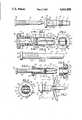
- FIG. 1is a top plan view of the wall anchor comprising the socket and a pointed drive pin;
- FIG. 2is a side elevation view of the socket with portions shown in longitudinal medial section;
- FIG. 3is a front elevation view of the lead end of the socket
- FIG. 4is a view in section taken along the line 4--4 of FIG. 2;
- FIG. 5is a side elevation view of another embodiment of the drive pin
- FIG. 6is a side elevation view similar to that of FIG. 2 but showing the drive pin in the socket in a ready position;
- FIG. 7is a side elevation view of the socket and drive pin showing the drive pin fully inserted in the socket with the fingers extended by the cam action of the drive pin;
- FIG. 8is an enlarged view in medial section of the central portion of the socket showing the web with the pin driven through it.
- this wall anchor 10includes a socket 12 and a drive pin 14.
- the socket 12receives the drive pin 14 in a manner and for purposes which will be described hereinafter.
- the socket 12includes a body section 16, a head 18, and a finger section 20. There is a passage 21 through the head 18 and the body section 16 communicating with the finger section 20.
- the finger section 20includes two fingers 22 and 24 having flat outer surfaces 26 and 28, respectively, terminating in tapered nose sections 30 and 32 at the lead end of the socket 12.
- the fingers 22 and 24have opposed flat faces 34 and 36, and the finger 22 has side walls 38 and 40, the other finger 24 having side walls 42 and 44.
- the longitudinal corners 46 of the finger 22 and the corners 48 of the finger 24are chamfered as shown in FIG. 3.
- the fingers 22 and 24Toward their trailing ends, the fingers 22 and 24 have barbs 50 and 52, respectively, that are sawtooth in side elevation as shown in FIG. 2.
- the fingers 22 and 24are formed with transverse walls 53 and 54 that extend across the lead end of the passage 21. Preferably, these walls 53 and 54 are inclined inwardly and toward the head 18 at angles of about 60° of the axis of the passage 21. Spaced from the walls 53 and 54, a web 55 is formed integral with the socket 12. A slit across the width of the web parallel to the faces 34 and 36 has opposed edges 56 and 57. The slit separates the web into halves 58 and 59 which, as shown in FIG. 2, are generally parallel to the walls 53 and 54.
- the short sections 60 and 61can be unstressed and even rounded as shown in FIGS. 2 and 6.
- These short sections 60 and 61are molded as integral parts of the plastic socket 12 and are of generally the same thickness as that of the wall of the central portion 16 of the socket. Since these sections 60 and 61 are relatively thin, they can bend and act as hinge connections between the fingers 22 and 24, respectively, and the body section 16. In the molded condition, the fingers 22 and 24 are straight and together in the positions shown in FIGS. 2 and 6, held there by the internal memory of the plastic hinges 60 and 61, until forcefully expanded.
- a plurality of longitudinally extending ribs 62project inwardly on the inner wall of the passage 21.
- the primary purpose of these ribs 62is to grip the shank of the drive pin 14 as shown in FIG. 6, holding the pin 14 in a ready condition.
- the circumscribed diameter defined by the ribs 62is slightly less than the diameter of the shank of the drive pin 14.
- rings 64On the outer surface of the central section 16, there are a plurality of rings 64 that are generally sawtooth in side elevation.
- the outer diameters of the rings 64are essentially the same as the span between the barbs 50 and 52 so that both the fingers 22 and 24 and the central portion 16 of the socket 12 will fit in the same size hole in a wall.
- a span 67 of the socket 12 between the barbs 66 and the head 18is about as long as the thickness of a part P that is to be mounted to a wall W.
- These barbs 66define a circumscribed circle, the diameter of which is greater than that of the rings 64.
- the function of the barbs 66is to engage one side of a part P while the head 18 engages the other side to thereby retain the socket 18 within a hole in the part prior to installation on a wall.
- the drive pin 14has a shank 70 with a point 71 on its lead end.
- the drive pin 14has a blunter point 72, which may be semi-spherical.
- the lead section 73 of the shank 70is cylindrical like a nail, whereas the trailing section is formed with double helix threads 74.
- the double helix threads 74are sawtooth in side elevation, as shown in FIG. 5, with the leading faces of the threads at an angle of about 15° to the axis of the drive pin. This enables the drive pin to be driven, such as by a hammer, into the socket with minimal interference from the threads 74.
- the threads 74will grip the inner wall of the passage 22 to withdraw the drive pin when it is turned by a screwdriver.
- a screwdriver kerf 78or phillips slot, in it.
- the diameter of the leading cylindrical section 73is about equal to the internal diameter of the passage 21, but is greater than the diameter circumscribed by the ribs 62. Therefore, when the drive pin 14 is started into the passage 22 and pressed within the longitudinal ribs 62, the ribs 62 will grip the pin 14 and hold it in place. Because the socket 12 is plastic, it will yield, and the pin can be inserted manually.
- the wall anchorIf the wall anchor is to be used to mount a part P to a wall W, it will have been molded with the span 67 between the head 18 and the barbs 66 slightly greater than the thickness of the part P.
- the part Pwill have been provided with a hole through it, the diameter of which is about equal to the outer diameter of the span 67, but less than the circumscribed diameter of the barbs 66.
- the barbs 66When the socket 12 is pressed into such a hole, the barbs 66 will yield and the socket can be snapped into place with the head 18 on one side of the part P, and the barbs 66 on the other side, thereby retaining the socket 12 on the part.
- the drive pin 14is pressed into the passage 21 until the leading portion 73 of the shank 70 is pressed within the area of the ribs 62. These ribs 62 will hold the drive pin 14 in place.
- Another stepis to drill a hole in a wall W, the diameter of which is slightly greater than the diameter of the body of the socket 12, and less than the diameter of the rings 64.
- the socket 12can then be pushed into the hole in the wall W, and the rings 64 will hold it in place temporarily.
- a hammercan drive against the head 76 of the drive pin 14. As the drive pin 14 projects further into the socket 12, it presses against the web 55, deflecting the web sections 58 and 59 toward the finger section 20.
- the pin 14engages the transverse faces 54 and 56 of the fingers 22 and 24 and pivots the fingers toward the ninety degree orientations shown in FIG. 7.
- the web halves 58 and 59are now stretched along the pin shank 70, placing their edges 56 and 57 in positions to help hold the fingers 22 and 24 in their spread positions.
- the barbs 50 and 52grip the wall surface as shown in FIG. 7.
- the kerf, or phillips slot, 78 in the drive pinallows it to be rotated by a screwdriver in a direction that will cause the double helical threads 74 to withdraw the drive pin from the socket 12.
Landscapes
- Engineering & Computer Science (AREA)
- General Engineering & Computer Science (AREA)
- Mechanical Engineering (AREA)
- Supports Or Holders For Household Use (AREA)
Abstract
Description
This invention relates to a wall anchor and particularly to a wall anchor comprising a socket having a body portion with fingers integrally hinged thereto and also comprising a drive pin that can be driven into the socket to spread the fingers by a camming action. The invention further relates to a wall anchor that can attach a part to a wall and that incorporates means to retain the wall anchor on the part prior to attachment to the wall.
Various wall anchors, including those with laterally expandable fingers, have been devised. These earlier wall anchors have been made of various materials, including plastic. However, there are unique features of this invention, which include a socket that is a unitary molded plastic member having a head on one end, a body section in the center, and fingers hinged at the other end, outwardly projecting barbs spaced from the head, with a passage through the head and body communicating with the fingers, wherein the fingers have transverse walls in the path of the passage, combined with a pin that can be driven by a hammer through the passage into contact with the transverse walls to act as a cam and pivot the fingers laterally outwardly.
The transverse walls are preferably inclined inwardly and toward the head of the socket so that the pin will pivot the fingers as far outwardly as possible toward ninety degree projections relative to the axis of the passage.
A special feature of this invention is the provision of a web slightly spaced from the transverse walls. There is a small opening through the web, such as a slit. Without the web, a stress line would be formed during molding, the end of the core forming the passage where that core intersects the transverse walls. By providing the web, the location of the stress line is moved to the intersection of the core and the web, and the walls joining the web and the transverse walls can be formed rounded with no stress lines. This avoids failure at the pivot lines of the fingers that might result from stress lines.
The web performs another function. As the drive pin is driven through the passage, it first contacts the web and, because the slit is parallel to the pivot lines of the fingers, the pin will split the web and pivot its halves toward the fingers. Thereafter, when the pin cams the fingers outwardly, the web halves lie against the pin and present edges opposing a tendency of the transverse walls to slide back along the pin. A particular advantage in the present wall anchor is that it is molded with the fingers positioned together. Therefore, it is not necessary to squeeze the fingers together to insert the socket into a pre-drilled hole in a wall.
Additional features of this wall anchor which are distinctive include longitudinal ribs on the inner wall of the passage to grip the shank of the drive pin, barbs on the outer wall of the shank, adjacent the head thereof, to snap the socket within a hole provided in another part that is to be secured to a wall surface, a head on the socket that acts as a positive stop against the wall surface or against the part, sawtooth rings on the outer body surface of the socket to frictionally engage a hole in a wall, and ridges on the outer surfaces of the fingers that frictionally engage the wall when the fingers are laterally extended. These ridges are on generally flat outer faces of the fingers which therefore maintain maximum contact area with the wall surface when the fingers are spread and laterally extended. However, the outer longitudinal corners of the fingers are chamfered to keep the fingers within the general overall diameter of the socket, and within the overall diameter of a hole in the wall into which the socket is to be mounted. The leading end of each finger is tapered to facilitate introduction of the socket into the hole in the wall.
In addition to these important features of the socket, the pin is also distinct in that it comprises a lead section that is generally like a nail. This lead section is normally held within the ribbed portion of the passage in the socket in a ready position. The trailing end of the drive pin has a head on it with a kerf in it that is sized to receive a screwdriver, or a phillips head slot, and adjacent the head, the drive pin preferably has threads that are typically in a double helix. The threads have a sawtooth contour so that the drive pin can be driven in the direction of its lead end but will respond to a screwdriver when rotated in a counter clockwise direction to withdraw the pin from the socket.
The drive pin may have a sharp point on its lead end, as a nail point, or it may be rather blunt, or semi-spherical. The semi-spherical point functions well to avoid the aforesaid wedging between the fingers, cooperating with the inclined transverse walls to produce the desired camming action. If a point is used, is should be driveable into a wood stud, but not too sharp to jam between the fingers and avoid the camming action.
On the other hand, an advantage of the pointed drive pin is that, if the anchor is placed in a predrilled hole in a stud that restrains the fingers from pivoting laterally, the sharp point will lead the pin into a wedging position between the fingers and wedge them tightly against the side walls of such a hole. In such a use, the edges of the outer surfaces of the fingers are particularly effective in holding the anchor in place, and the sawtooth configuration of these ridges is an additional aid in the effectiveness of the grip.
The invention provides an inexpensive wall anchor in that the socket is a single piece and can be readily produced by molding plastic. The camming action between the drive pin and the transverse walls on the fingers produces maximum spread of the fingers and results in a stronger installation on the wall. The barbs spaced from the head allow the socket to be snapped in place and held in the hole of a part that is to be mounted on the wall. The longitudinal ribs hold the drive pin in the socket but withdrawn from the fingers so the socket can be pushed into a hole in the wall.
FIG. 1 is a top plan view of the wall anchor comprising the socket and a pointed drive pin;
FIG. 2 is a side elevation view of the socket with portions shown in longitudinal medial section;
FIG. 3 is a front elevation view of the lead end of the socket;
FIG. 4 is a view in section taken along theline 4--4 of FIG. 2;
FIG. 5 is a side elevation view of another embodiment of the drive pin;
FIG. 6 is a side elevation view similar to that of FIG. 2 but showing the drive pin in the socket in a ready position;
FIG. 7 is a side elevation view of the socket and drive pin showing the drive pin fully inserted in the socket with the fingers extended by the cam action of the drive pin; and
FIG. 8 is an enlarged view in medial section of the central portion of the socket showing the web with the pin driven through it.
As shown in FIG. 1, the principal components of thiswall anchor 10 include asocket 12 and adrive pin 14. Thesocket 12 receives thedrive pin 14 in a manner and for purposes which will be described hereinafter.
Thesocket 12 includes abody section 16, ahead 18, and afinger section 20. There is apassage 21 through thehead 18 and thebody section 16 communicating with thefinger section 20. Thefinger section 20 includes twofingers outer surfaces tapered nose sections 30 and 32 at the lead end of thesocket 12. Inwardly, thefingers flat faces finger 22 hasside walls 38 and 40, theother finger 24 havingside walls longitudinal corners 46 of thefinger 22 and thecorners 48 of thefinger 24 are chamfered as shown in FIG. 3. Toward their trailing ends, thefingers barbs
Thefingers transverse walls passage 21. Preferably, thesewalls head 18 at angles of about 60° of the axis of thepassage 21. Spaced from thewalls web 55 is formed integral with thesocket 12. A slit across the width of the web parallel to thefaces opposed edges halves walls
Although the intersection of thepassage 21 and the web may have a stress line, theshort sections short sections plastic socket 12 and are of generally the same thickness as that of the wall of thecentral portion 16 of the socket. Since thesesections fingers body section 16. In the molded condition, thefingers plastic hinges
Referring to thecentral body section 16, a plurality of longitudinally extendingribs 62 project inwardly on the inner wall of thepassage 21. The primary purpose of theseribs 62 is to grip the shank of thedrive pin 14 as shown in FIG. 6, holding thepin 14 in a ready condition. In other words, the circumscribed diameter defined by theribs 62 is slightly less than the diameter of the shank of thedrive pin 14.
On the outer surface of thecentral section 16, there are a plurality ofrings 64 that are generally sawtooth in side elevation. The outer diameters of therings 64 are essentially the same as the span between thebarbs fingers central portion 16 of thesocket 12 will fit in the same size hole in a wall.
Between therings 64 and thehead 18, there are a plurality ofbarbs 66 on thecentral section 16. Aspan 67 of thesocket 12 between thebarbs 66 and thehead 18 is about as long as the thickness of a part P that is to be mounted to a wall W. Thesebarbs 66 define a circumscribed circle, the diameter of which is greater than that of therings 64. The function of thebarbs 66 is to engage one side of a part P while thehead 18 engages the other side to thereby retain thesocket 18 within a hole in the part prior to installation on a wall.
In its preferred form, as shown in FIG. 1, thedrive pin 14 has ashank 70 with apoint 71 on its lead end. In a modification as shown in FIG. 5, thedrive pin 14 has ablunter point 72, which may be semi-spherical. Generally, thelead section 73 of theshank 70 is cylindrical like a nail, whereas the trailing section is formed withdouble helix threads 74. Thedouble helix threads 74 are sawtooth in side elevation, as shown in FIG. 5, with the leading faces of the threads at an angle of about 15° to the axis of the drive pin. This enables the drive pin to be driven, such as by a hammer, into the socket with minimal interference from thethreads 74. On the other hand, since the trailing edges of thethreads 74 are preferably normal to the axis of the pin, thethreads 74 will grip the inner wall of thepassage 22 to withdraw the drive pin when it is turned by a screwdriver. For both driving and withdrawing thedrive pin 14, there is ahead 76 on the trailing end of thedrive pin 14 with ascrewdriver kerf 78, or phillips slot, in it. The diameter of the leadingcylindrical section 73 is about equal to the internal diameter of thepassage 21, but is greater than the diameter circumscribed by theribs 62. Therefore, when thedrive pin 14 is started into thepassage 22 and pressed within thelongitudinal ribs 62, theribs 62 will grip thepin 14 and hold it in place. Because thesocket 12 is plastic, it will yield, and the pin can be inserted manually.
If the wall anchor is to be used to mount a part P to a wall W, it will have been molded with thespan 67 between thehead 18 and thebarbs 66 slightly greater than the thickness of the part P. The part P will have been provided with a hole through it, the diameter of which is about equal to the outer diameter of thespan 67, but less than the circumscribed diameter of thebarbs 66. When thesocket 12 is pressed into such a hole, thebarbs 66 will yield and the socket can be snapped into place with thehead 18 on one side of the part P, and thebarbs 66 on the other side, thereby retaining thesocket 12 on the part.
Thedrive pin 14 is pressed into thepassage 21 until the leadingportion 73 of theshank 70 is pressed within the area of theribs 62. Theseribs 62 will hold thedrive pin 14 in place. Another step is to drill a hole in a wall W, the diameter of which is slightly greater than the diameter of the body of thesocket 12, and less than the diameter of therings 64. Thesocket 12 can then be pushed into the hole in the wall W, and therings 64 will hold it in place temporarily. Now, a hammer can drive against thehead 76 of thedrive pin 14. As thedrive pin 14 projects further into thesocket 12, it presses against theweb 55, deflecting theweb sections finger section 20. Thereafter, thepin 14 engages the transverse faces 54 and 56 of thefingers pin shank 70, placing theiredges fingers barbs
When it is desired to remove the wall anchor, the kerf, or phillips slot, 78 in the drive pin allows it to be rotated by a screwdriver in a direction that will cause the doublehelical threads 74 to withdraw the drive pin from thesocket 12. Once the drive pin has cleared thefaces fingers
There are various changes and modifications which may be made to this invention as would be apparent to those skilled in the art. However, any of these changes or modifications are included in the teaching of this disclosure and this invention is limited only by the scope of the claims appended hereto.
Claims (23)
1. A wall anchor comprising a molded plastic socket and a pin, the socket comprising a body section having a lead end and a trailing end, a passage through the body section for receiving the pin, a pair of elongated fingers integral with the body section and extending from the lead end of the body section, the fingers having thin wall portions joining them to the body section, the thin wall portions being bendable to act as hinges allowing the fingers to swing between normally closed positions in which the outer extremes of the fingers allow the fingers to fit within a predetermined hole in a building wall and spread positions in which the fingers are pivoted laterally outwardly relative to the body section and will not fit through the hole, the fingers being sufficiently long to enable them to be pivoted by a person's fingers, the socket being molded to position the fingers in the normally closed positions to allow the socket to be inserted into the hole in the wall without requiring an external force squeezing the fingers together, the fingers having transverse walls extending across transverse portions of the passage in the path of the pin whereby projection of the pin beyond the leading end of the body section presses the lead end of the pin against the transverse walls of the fingers in a cam action to pivot the fingers to the spread positions, and a plurality of radially inwardly extending longitudinal ribs on the wall of the passage to grip the pin, the ribs being shaped to maintain pressure in a radial direction against the pin upon insertion and extension of the pin in the passage whereby the socket will support and retain the pin prior to installation of the wall anchor, the combination of the ribs retaining the pin and the fingers normally occupying closed positions enabling the wall anchor including the socket and the pin to be inserted in the hole in the wall by one hand.
2. The wall anchor of claim 1 wherein the body section has a generally round cross-section and the fingers are generally rectangular in cross section with flat outer faces to contact the building wall and with chamfered longitudinal outer corners to enable the fingers to pass through the hole.
3. The wall anchor of claim 2 wherein the fingers have tapered leading ends to facilitate introduction into the predetermined hole.
4. The wall anchor of claim 1 including a plurality of axially spaced rings on the outer surface of the body section adjacent the trailing end thereof.
5. The wall anchor of claim 4 including a head on the trailing end of the body section, the passage extending through the head, a plurality of barbs on the outer surface of the body section equally spaced from the head and located between the head and the rings, the circumscribed diameter of the barbs being less than the diameter of the head and being greater than the diameter of the body section.
6. The wall anchor of claim 5 wherein each barb is defined by a leading face at an angle of less than about 30° to the axis of the socket, and a trailing face at an angle of greater than 60° to the axis of the socket.
7. The wall anchor of claim 1 wherein the transverse walls of the fingers are inclined toward the body section, the pin comprising a shank having a leading end and a trailing end, the leading end terminating generally in a hemisphere to assure contact with the transverse walls and avoid jamming between the fingers, a head on the trailing end allowing it to be driven into the socket, and threads on at least a portion of the shank.
8. The wall anchor of claim 7 including slot means in the head for receiving a screwdriver.
9. The wall anchor of claim 7 wherein the threads are helical and have leading and trailing faces, the leading faces being at angles of less than 45° to the axis of the shank and the trailing faces being at angles of greater than 45° to the axis of the shank.
10. The wall anchor of claim 9 wherein the threads are on about one-half the shank adjacent the trailing end thereof and the remainder of the shank adjacent the leading end thereof is cylindrical.
11. A wall anchor comprising a pin and socket wherein the socket includes a body section with a leading end and a trailing end, a pair of fingers hinged to the trailing end and being pivotable relative to the body section, an annular wall surface defining a passage through the body section for receiving the pin, the fingers having transverse walls extending inwardly from the annular inner wall surface in the path of the pin and cooperable with the pin for pivoting the fingers to laterally extending positions, and a web in the passage between the walls of the fingers and the trailing end, the web being independent of the fingers and joined to the socket and extending inwardly from the inner wall surface for interception by the pin before the pin reaches the transverse walls.
12. The wall anchor of claim 11 including a slit in the web enabling the pin to split the web into two halves pressed against the transverse walls.
13. The wall anchor of claim 11 wherein the web is spaced from the walls of the fingers.
14. The wall anchor of claim 11 including a plurality of ribs formed on the body section projecting axially inwardly of the passage wall, the diameter of the pin being greater than the diameter circumscribed by the inward extensions of the ribs and being less than the diameter of the passage whereby the pin can be manually pressed into the passage and held there by the ribs, the pin having a leading end and a trailing end, a point on the leading end, a generally cylindrical shank portion adjacent the point and terminating intermediate the leading end and the trailing end and being longer than the ribs, and helical threads between the cylindrical shank portion and the trailing end, the maximum diameter of the threads being greater than the diameter of the passage.
15. The wall anchor of claim 14 wherein the threads are defined by leading surfaces at less than 45° to the axis of the pin and trailing surfaces at greater than 45° to the axis of the pin, a head on the trailing end of the pin to facilitate driving the pin with a hammer, and a kerf in the head to receive a screwdriver.
16. The wall anchor of claim 15 wherein the trailing surfaces are at about 90° to the axis of the pin.
17. The wall anchor of claim 11 wherein the walls of the fingers are inclined inwardly and toward the trailing end.
18. The wall anchor of claim 17 wherein the angle of inclination is between about 55 degrees and about 65 degrees to the axis of the passage.
19. The wall anchor of claim 17 wherein the web has portions generally parallel to the walls of the fingers.
20. A wall anchor for mounting a part to a wall wherein the part has a hole in it for receiving the wall anchor, comprising a pin and a plastic socket, the socket having a body section and a finger section, a passage through the body section for receiving the pin, the finger section comprising a pair of fingers, short bendable sections for connecting the respective fingers to a first end of the body section and allowing them to pivot about the body section, the fingers having walls in the path of the passage to pivot the fingers laterally relative to the body section upon engagement between the walls and the pin, a head on a second end of the body section, a retainer means projecting outwardly from and located circumferentially about the body section, the retainer means being spaced from the head and cooperating with the head to define a circumferential retainer section therebetween, the diameter of the retainer section being smaller than the diameter of the hole in the part, the diameter of the head and the circumscribed diameter of the retainer means being greater than the diameter of the hole in the part, whereby the socket can be snapped within the hole in the part and the part can be held in place within the retainer section by the head on one side of the part and the retainer means on the other side of the part.
21. The wall anchor of claim 20 wherein the fingers have flat outer faces and outer longitudinal edges that are chamfered, enabling the fingers to fit through the hole while maximizing contact area between the fingers and the wall when the anchor is mounting the part to the wall.
22. The wall anchor of claim 20 wherein the retainer means comprises a plurality of barbs, each barb having a first surface facing the first end of the body section and a second surface facing the second end of the body section, the first surface being at an angle of less than about 25° to the axis of the body section, the second surface being at an angle of greater than 75° to the axis of the body section.
23. The wall anchor of claim 22 wherein the second surface is at an angle of at least 85° to the axis of the body section.
Priority Applications (1)
| Application Number | Priority Date | Filing Date | Title |
|---|---|---|---|
| US06/783,163US4662808A (en) | 1985-10-02 | 1985-10-02 | Wall anchor |
Applications Claiming Priority (1)
| Application Number | Priority Date | Filing Date | Title |
|---|---|---|---|
| US06/783,163US4662808A (en) | 1985-10-02 | 1985-10-02 | Wall anchor |
Publications (1)
| Publication Number | Publication Date |
|---|---|
| US4662808Atrue US4662808A (en) | 1987-05-05 |
Family
ID=25128373
Family Applications (1)
| Application Number | Title | Priority Date | Filing Date |
|---|---|---|---|
| US06/783,163Expired - LifetimeUS4662808A (en) | 1985-10-02 | 1985-10-02 | Wall anchor |
Country Status (1)
| Country | Link |
|---|---|
| US (1) | US4662808A (en) |
Cited By (96)
| Publication number | Priority date | Publication date | Assignee | Title |
|---|---|---|---|---|
| US4789285A (en)* | 1986-03-29 | 1988-12-06 | Artur Fischer Gmbh & Co. Kg | Anchoring plug |
| US4871289A (en)* | 1988-11-25 | 1989-10-03 | Olympic Manufacturing Group, Inc. | Expansion fastener |
| US4890966A (en)* | 1987-08-07 | 1990-01-02 | Nifco, Inc. | Securing clip |
| US5022804A (en)* | 1989-02-14 | 1991-06-11 | Buell Industries, Inc. | Self-mounting fastener |
| US5037257A (en)* | 1990-09-11 | 1991-08-06 | Roll It Inc. | Wall plug and anchor assembly |
| US5161296A (en)* | 1991-07-30 | 1992-11-10 | Mechanical Plastics Corp | Method of securing an anchor with extrusion plastic molding in a solid wall substrate |
| US5244324A (en)* | 1992-08-18 | 1993-09-14 | Dry Dock Industries, Inc. | Anchoring retainer for threaded fastener |
| FR2704912A1 (en)* | 1993-05-08 | 1994-11-10 | Franke Gmbh & Co Kg | Fittings capable of being fixed to a piece of wood furniture made of a similar material. |
| US5393179A (en)* | 1994-02-22 | 1995-02-28 | Bane; Robert F. | Anchor with drive pin and threadable bolt |
| WO1997032142A1 (en)* | 1996-02-28 | 1997-09-04 | Adolf Würth GmbH & Co. KG | Knock-in pin dowel |
| US5716179A (en)* | 1997-02-14 | 1998-02-10 | Smith; Lester | Non-articulated ball and tube spring biased toggle |
| US6102638A (en)* | 1998-04-14 | 2000-08-15 | Alfit Aktiengesellschaft | Pre-assembled structural part and fastener |
| DE19950746A1 (en)* | 1999-04-01 | 2000-12-07 | Simon Karl Gmbh & Co Kg | Mounting element for furniture comprises a joining plug and a fixing sleeve with springs |
| US6254325B1 (en) | 2000-01-28 | 2001-07-03 | Steve Kun | Anchor assembly for a wall, floor or like supporting structure |
| NL1014656C2 (en)* | 2000-03-15 | 2001-09-19 | Wit J H En Zonen De | Universal impact screw plug unit. |
| US20030170093A1 (en)* | 2000-04-27 | 2003-09-11 | David Janeway | Fastening device with adjustable fastening surface embedded in cast panel or other products |
| US20050076602A1 (en)* | 2003-09-17 | 2005-04-14 | Raymond Routhier | Asymmetric drive pin |
| US20050149030A1 (en)* | 2003-12-19 | 2005-07-07 | Depuy Spine, Inc. | Facet joint fixation system |
| US20050158139A1 (en)* | 2002-08-08 | 2005-07-21 | Hepworth Paul S. | Fixing plug |
| US20050214095A1 (en)* | 2004-03-24 | 2005-09-29 | Brown Brian A | Wall and ceiling fastening system and methods therefor |
| US20060222474A1 (en)* | 2004-03-24 | 2006-10-05 | Brown Brian A | System and methods for wall and ceiling fastening |
| US20060264938A1 (en)* | 2005-03-21 | 2006-11-23 | St. Francis Medical Technologies, Inc. | Interspinous process implant having deployable wing and method of implantation |
| US20060265066A1 (en)* | 2005-03-21 | 2006-11-23 | St. Francis Medical Technologies, Inc. | Interspinous process implant having a thread-shaped wing and method of implantation |
| US20060271049A1 (en)* | 2005-04-18 | 2006-11-30 | St. Francis Medical Technologies, Inc. | Interspinous process implant having deployable wings and method of implantation |
| US20070043363A1 (en)* | 2005-02-17 | 2007-02-22 | Malandain Hugues F | Percutaneous spinal implants and methods |
| US20070043362A1 (en)* | 2005-02-17 | 2007-02-22 | Malandain Hugues F | Percutaneous spinal implants and methods |
| US20070073292A1 (en)* | 2005-02-17 | 2007-03-29 | Kohm Andrew C | Percutaneous spinal implants and methods |
| US20070176465A1 (en)* | 2006-01-30 | 2007-08-02 | Solus Solutions And Technologies, Llc | Frame extension device for reducing the aerodynamic drag of ground vehicles |
| US20070250060A1 (en)* | 2006-04-24 | 2007-10-25 | Sdgi Holdings, Inc. | Expandable device for insertion between anatomical structures and a procedure utilizing same |
| US20070265623A1 (en)* | 2005-02-17 | 2007-11-15 | Malandain Hugues F | Percutaneous Spinal Implants and Methods |
| US20070270827A1 (en)* | 2006-04-28 | 2007-11-22 | Warsaw Orthopedic, Inc | Adjustable interspinous process brace |
| US20080033558A1 (en)* | 2002-10-29 | 2008-02-07 | Zucherman James F | Interspinous process implants and methods of use |
| US20080051905A1 (en)* | 1997-01-02 | 2008-02-28 | Zucherman James F | Supplemental spine fixation device and method |
| US20080071280A1 (en)* | 2004-04-28 | 2008-03-20 | St. Francis Medical Technologies, Inc. | System and Method for Insertion of an Interspinous Process Implant that is Rotatable in Order to Retain the Implant Relative to the Spinous Processes |
| US20080081896A1 (en)* | 2006-09-28 | 2008-04-03 | Helmut-Werner Heuer | (Co)polycarbonates having improved adhesion to metals |
| US20080114456A1 (en)* | 2006-11-15 | 2008-05-15 | Warsaw Orthopedic, Inc. | Spinal implant system |
| US20080199275A1 (en)* | 2006-05-18 | 2008-08-21 | Brown Brian A | Anchoring fastener with movable binding member |
| US20090051237A1 (en)* | 2005-12-16 | 2009-02-26 | Bsh Bosch Und Siemens Hausgerate Gmbh | Fastening Device for a Motor in a Household Appliance |
| US20090198338A1 (en)* | 2008-02-04 | 2009-08-06 | Phan Christopher U | Medical implants and methods |
| US20100042217A1 (en)* | 1997-01-02 | 2010-02-18 | Kyphon Sarl | Spine distraction implant and method |
| US20100067975A1 (en)* | 2008-09-14 | 2010-03-18 | Brown Brian A | Hinged wall and ceiling anchor with fins and hinge |
| US20100174316A1 (en)* | 2003-05-22 | 2010-07-08 | Kyphon Sarl | Distractible interspinous process implant and method of implantation |
| WO2010041820A3 (en)* | 2008-10-09 | 2010-07-15 | (유)정명산업 | Traffic lane delineator and anchor used in same |
| US20100262243A1 (en)* | 1997-01-02 | 2010-10-14 | Kyphon Sarl | Spine distraction implant |
| US20100305611A1 (en)* | 2002-10-29 | 2010-12-02 | Kyphon Sarl | Interspinous process apparatus and method with a selectably expandable spacer |
| US7846186B2 (en) | 2005-06-28 | 2010-12-07 | Kyphon SÀRL | Equipment for surgical treatment of two vertebrae |
| US20100318127A1 (en)* | 2009-06-12 | 2010-12-16 | Kyphon Sarl | Interspinous implant and methods of use |
| US20100329819A1 (en)* | 2008-03-03 | 2010-12-30 | Illinois Tool Works Inc. | Hollow wall fastener |
| US20110098745A1 (en)* | 2009-10-28 | 2011-04-28 | Kyphon Sarl | Interspinous process implant and method of implantation |
| US7955392B2 (en) | 2006-12-14 | 2011-06-07 | Warsaw Orthopedic, Inc. | Interspinous process devices and methods |
| US20110144697A1 (en)* | 2005-02-17 | 2011-06-16 | Kyphon Sarl | Percutaneous spinal implants and methods |
| US7988709B2 (en) | 2005-02-17 | 2011-08-02 | Kyphon Sarl | Percutaneous spinal implants and methods |
| US20110224764A1 (en)* | 2010-03-11 | 2011-09-15 | Lee Kulle | Implantable anchor for medical stimulation leads |
| US8029567B2 (en) | 2005-02-17 | 2011-10-04 | Kyphon Sarl | Percutaneous spinal implants and methods |
| US8034079B2 (en) | 2005-04-12 | 2011-10-11 | Warsaw Orthopedic, Inc. | Implants and methods for posterior dynamic stabilization of a spinal motion segment |
| US8038698B2 (en) | 2005-02-17 | 2011-10-18 | Kphon Sarl | Percutaneous spinal implants and methods |
| US8043378B2 (en) | 2006-09-07 | 2011-10-25 | Warsaw Orthopedic, Inc. | Intercostal spacer device and method for use in correcting a spinal deformity |
| US8048117B2 (en) | 2003-05-22 | 2011-11-01 | Kyphon Sarl | Interspinous process implant and method of implantation |
| US8048119B2 (en) | 2006-07-20 | 2011-11-01 | Warsaw Orthopedic, Inc. | Apparatus for insertion between anatomical structures and a procedure utilizing same |
| US20110268527A1 (en)* | 2010-05-03 | 2011-11-03 | Powers Products Iii, Llc | Wall anchor |
| US8070778B2 (en) | 2003-05-22 | 2011-12-06 | Kyphon Sarl | Interspinous process implant with slide-in distraction piece and method of implantation |
| US8083795B2 (en) | 2006-01-18 | 2011-12-27 | Warsaw Orthopedic, Inc. | Intervertebral prosthetic device for spinal stabilization and method of manufacturing same |
| US8096994B2 (en) | 2005-02-17 | 2012-01-17 | Kyphon Sarl | Percutaneous spinal implants and methods |
| US8097018B2 (en) | 2005-02-17 | 2012-01-17 | Kyphon Sarl | Percutaneous spinal implants and methods |
| US8109705B1 (en) | 2007-02-23 | 2012-02-07 | Illinois Tool Works Inc. | Twist-lock anchoring fastener |
| US8114136B2 (en) | 2008-03-18 | 2012-02-14 | Warsaw Orthopedic, Inc. | Implants and methods for inter-spinous process dynamic stabilization of a spinal motion segment |
| US8114132B2 (en) | 2010-01-13 | 2012-02-14 | Kyphon Sarl | Dynamic interspinous process device |
| US8114131B2 (en) | 2008-11-05 | 2012-02-14 | Kyphon Sarl | Extension limiting devices and methods of use for the spine |
| US8118839B2 (en) | 2006-11-08 | 2012-02-21 | Kyphon Sarl | Interspinous implant |
| US8128663B2 (en) | 1997-01-02 | 2012-03-06 | Kyphon Sarl | Spine distraction implant |
| CN102374213A (en)* | 2010-08-12 | 2012-03-14 | 鸿富锦精密工业(深圳)有限公司 | Spring claw fixing device |
| US8147526B2 (en) | 2010-02-26 | 2012-04-03 | Kyphon Sarl | Interspinous process spacer diagnostic parallel balloon catheter and methods of use |
| US8157841B2 (en) | 2005-02-17 | 2012-04-17 | Kyphon Sarl | Percutaneous spinal implants and methods |
| USD660139S1 (en) | 2010-09-27 | 2012-05-22 | Powers Products Iii, Llc | Anchor |
| US8226653B2 (en) | 2005-04-29 | 2012-07-24 | Warsaw Orthopedic, Inc. | Spinous process stabilization devices and methods |
| US8262698B2 (en) | 2006-03-16 | 2012-09-11 | Warsaw Orthopedic, Inc. | Expandable device for insertion between anatomical structures and a procedure utilizing same |
| US8317831B2 (en) | 2010-01-13 | 2012-11-27 | Kyphon Sarl | Interspinous process spacer diagnostic balloon catheter and methods of use |
| US8372117B2 (en) | 2009-06-05 | 2013-02-12 | Kyphon Sarl | Multi-level interspinous implants and methods of use |
| US20130269169A1 (en)* | 2011-08-18 | 2013-10-17 | Empire Technology Development Llc | Hinged arm mechanically activated fastener |
| US8591548B2 (en) | 2011-03-31 | 2013-11-26 | Warsaw Orthopedic, Inc. | Spinous process fusion plate assembly |
| US8591549B2 (en) | 2011-04-08 | 2013-11-26 | Warsaw Orthopedic, Inc. | Variable durometer lumbar-sacral implant |
| US8641762B2 (en) | 2006-10-24 | 2014-02-04 | Warsaw Orthopedic, Inc. | Systems and methods for in situ assembly of an interspinous process distraction implant |
| US8679161B2 (en) | 2005-02-17 | 2014-03-25 | Warsaw Orthopedic, Inc. | Percutaneous spinal implants and methods |
| US8814908B2 (en) | 2010-07-26 | 2014-08-26 | Warsaw Orthopedic, Inc. | Injectable flexible interspinous process device system |
| US20150045886A1 (en)* | 2009-04-22 | 2015-02-12 | The Cleveland Clinic Foundation | Apparatus and method for sequentially anchoring multiple graft ligaments in a bone tunnel |
| US9347475B2 (en)* | 2011-04-25 | 2016-05-24 | Empire Technology Development Llc | Self-locating mechanically activated fastener |
| RU2611778C2 (en)* | 2015-10-22 | 2017-03-01 | Юрий яковлевич Курлов | Anchor for coal mines |
| US10001157B2 (en)* | 2014-07-29 | 2018-06-19 | Fischerwerke Gmbh & Co. Kg | Expansible fixing plug |
| US10001155B2 (en)* | 2014-07-29 | 2018-06-19 | Fischerwerke Gmbh & Co. Kg | Expansible fixing plug |
| US10632322B2 (en)* | 2018-07-27 | 2020-04-28 | Hua Shang | Memory metal optical fiber puncture needle tubing |
| US10641306B2 (en)* | 2017-03-03 | 2020-05-05 | Chun Yen Huang | Fixing bolt |
| US20220373015A1 (en)* | 2021-05-19 | 2022-11-24 | Rudor M. Teich | Fixed Engagement Anchor |
| USD986044S1 (en)* | 2020-08-03 | 2023-05-16 | Simpson Strong-Tie Company Inc. | Fastener sleeve |
| KR102582917B1 (en)* | 2023-04-05 | 2023-09-26 | 라온시스템가구(주) | fastening device for frame fixture for furniture |
| WO2023225480A1 (en)* | 2022-05-17 | 2023-11-23 | Berry Eben | Target retaining device |
| USD1034158S1 (en)* | 2020-08-03 | 2024-07-09 | Simpson Strong-Tie Company Inc. | Fastener sleeve |
Citations (8)
| Publication number | Priority date | Publication date | Assignee | Title |
|---|---|---|---|---|
| GB191001226A (en)* | 1910-01-17 | 1910-12-01 | Carl August Muller | Improvements in Screws. |
| US2033100A (en)* | 1932-10-20 | 1936-03-03 | Johns Manville | Structural assembly |
| US2555420A (en)* | 1945-05-02 | 1951-06-05 | Gay M Richardson | Fastener |
| US3188905A (en)* | 1962-04-03 | 1965-06-15 | David I Millet | Fastening device with pivotal locking means |
| US3213745A (en)* | 1962-09-13 | 1965-10-26 | James E Dwyer | Anchoring socket for screw type fasteners |
| US3431813A (en)* | 1967-08-03 | 1969-03-11 | Kenneth C Johnson | Hollow wall fastener |
| US4022100A (en)* | 1975-08-13 | 1977-05-10 | Johnson Kenneth C | Fastener |
| US4274324A (en)* | 1978-04-18 | 1981-06-23 | Giannuzzi Louis | Hollow wall screw anchor |
- 1985
- 1985-10-02USUS06/783,163patent/US4662808A/ennot_activeExpired - Lifetime
Patent Citations (8)
| Publication number | Priority date | Publication date | Assignee | Title |
|---|---|---|---|---|
| GB191001226A (en)* | 1910-01-17 | 1910-12-01 | Carl August Muller | Improvements in Screws. |
| US2033100A (en)* | 1932-10-20 | 1936-03-03 | Johns Manville | Structural assembly |
| US2555420A (en)* | 1945-05-02 | 1951-06-05 | Gay M Richardson | Fastener |
| US3188905A (en)* | 1962-04-03 | 1965-06-15 | David I Millet | Fastening device with pivotal locking means |
| US3213745A (en)* | 1962-09-13 | 1965-10-26 | James E Dwyer | Anchoring socket for screw type fasteners |
| US3431813A (en)* | 1967-08-03 | 1969-03-11 | Kenneth C Johnson | Hollow wall fastener |
| US4022100A (en)* | 1975-08-13 | 1977-05-10 | Johnson Kenneth C | Fastener |
| US4274324A (en)* | 1978-04-18 | 1981-06-23 | Giannuzzi Louis | Hollow wall screw anchor |
Cited By (155)
| Publication number | Priority date | Publication date | Assignee | Title |
|---|---|---|---|---|
| US4789285A (en)* | 1986-03-29 | 1988-12-06 | Artur Fischer Gmbh & Co. Kg | Anchoring plug |
| US4890966A (en)* | 1987-08-07 | 1990-01-02 | Nifco, Inc. | Securing clip |
| US4871289A (en)* | 1988-11-25 | 1989-10-03 | Olympic Manufacturing Group, Inc. | Expansion fastener |
| US5022804A (en)* | 1989-02-14 | 1991-06-11 | Buell Industries, Inc. | Self-mounting fastener |
| US5037257A (en)* | 1990-09-11 | 1991-08-06 | Roll It Inc. | Wall plug and anchor assembly |
| AU670764B2 (en)* | 1991-07-30 | 1996-08-01 | Mechanical Plastics Corporation | Method of securing an anchor with extrusion plastic molding in a solid wall substrate |
| US5161296A (en)* | 1991-07-30 | 1992-11-10 | Mechanical Plastics Corp | Method of securing an anchor with extrusion plastic molding in a solid wall substrate |
| JP3317701B2 (en) | 1991-07-30 | 2002-08-26 | メカニカル プラスチックス コーポレイション | Method of forming high strength fastener structure on solid wall |
| WO1994009929A1 (en)* | 1991-07-30 | 1994-05-11 | Mechanical Plastics Corp. | Method of securing an anchor with extrusion plastic molding in a solid wall substrate |
| RU2101580C1 (en)* | 1991-07-30 | 1998-01-10 | Меканикал Плавстикс Корп. | Method of forming high-strength member of anchor attachment in solid wall |
| US5244324A (en)* | 1992-08-18 | 1993-09-14 | Dry Dock Industries, Inc. | Anchoring retainer for threaded fastener |
| US5425609A (en)* | 1992-08-18 | 1995-06-20 | Dry Dock Industries, Inc. | Anchoring retainer for threaded fastener |
| FR2704912A1 (en)* | 1993-05-08 | 1994-11-10 | Franke Gmbh & Co Kg | Fittings capable of being fixed to a piece of wood furniture made of a similar material. |
| US5393179A (en)* | 1994-02-22 | 1995-02-28 | Bane; Robert F. | Anchor with drive pin and threadable bolt |
| WO1997032142A1 (en)* | 1996-02-28 | 1997-09-04 | Adolf Würth GmbH & Co. KG | Knock-in pin dowel |
| US7955356B2 (en) | 1997-01-02 | 2011-06-07 | Kyphon Sarl | Laterally insertable interspinous process implant |
| US8740943B2 (en) | 1997-01-02 | 2014-06-03 | Warsaw Orthopedic, Inc. | Spine distraction implant and method |
| US20080051904A1 (en)* | 1997-01-02 | 2008-02-28 | Zucherman James F | Supplemental spine fixation device and method |
| US8128663B2 (en) | 1997-01-02 | 2012-03-06 | Kyphon Sarl | Spine distraction implant |
| US8349013B2 (en) | 1997-01-02 | 2013-01-08 | Kyphon Sarl | Spine distraction implant |
| US8568455B2 (en) | 1997-01-02 | 2013-10-29 | Warsaw Orthopedic, Inc. | Spine distraction implant and method |
| US8568454B2 (en) | 1997-01-02 | 2013-10-29 | Warsaw Orthopedic, Inc. | Spine distraction implant and method |
| US20100262243A1 (en)* | 1997-01-02 | 2010-10-14 | Kyphon Sarl | Spine distraction implant |
| US20100042217A1 (en)* | 1997-01-02 | 2010-02-18 | Kyphon Sarl | Spine distraction implant and method |
| US8617211B2 (en) | 1997-01-02 | 2013-12-31 | Warsaw Orthopedic, Inc. | Spine distraction implant and method |
| US7901432B2 (en) | 1997-01-02 | 2011-03-08 | Kyphon Sarl | Method for lateral implantation of spinous process spacer |
| US7918877B2 (en) | 1997-01-02 | 2011-04-05 | Kyphon Sarl | Lateral insertion method for spinous process spacer with deployable member |
| US20080051905A1 (en)* | 1997-01-02 | 2008-02-28 | Zucherman James F | Supplemental spine fixation device and method |
| US7993374B2 (en) | 1997-01-02 | 2011-08-09 | Kyphon Sarl | Supplemental spine fixation device and method |
| US8821548B2 (en) | 1997-01-02 | 2014-09-02 | Warsaw Orthopedic, Inc. | Spine distraction implant and method |
| US5716179A (en)* | 1997-02-14 | 1998-02-10 | Smith; Lester | Non-articulated ball and tube spring biased toggle |
| US6102638A (en)* | 1998-04-14 | 2000-08-15 | Alfit Aktiengesellschaft | Pre-assembled structural part and fastener |
| DE19950746A1 (en)* | 1999-04-01 | 2000-12-07 | Simon Karl Gmbh & Co Kg | Mounting element for furniture comprises a joining plug and a fixing sleeve with springs |
| US6254325B1 (en) | 2000-01-28 | 2001-07-03 | Steve Kun | Anchor assembly for a wall, floor or like supporting structure |
| EP1134436A1 (en)* | 2000-03-15 | 2001-09-19 | J.H. De Wit En Zonen B.V. | Universal wall plug unit for hammer-driven and screwdriver-driven screws |
| NL1014656C2 (en)* | 2000-03-15 | 2001-09-19 | Wit J H En Zonen De | Universal impact screw plug unit. |
| US20030170093A1 (en)* | 2000-04-27 | 2003-09-11 | David Janeway | Fastening device with adjustable fastening surface embedded in cast panel or other products |
| US20050158139A1 (en)* | 2002-08-08 | 2005-07-21 | Hepworth Paul S. | Fixing plug |
| US20080033553A1 (en)* | 2002-10-29 | 2008-02-07 | Zucherman James F | Interspinous process implants and methods of use |
| US8007537B2 (en) | 2002-10-29 | 2011-08-30 | Kyphon Sarl | Interspinous process implants and methods of use |
| US20100305611A1 (en)* | 2002-10-29 | 2010-12-02 | Kyphon Sarl | Interspinous process apparatus and method with a selectably expandable spacer |
| US20080033558A1 (en)* | 2002-10-29 | 2008-02-07 | Zucherman James F | Interspinous process implants and methods of use |
| US20080065214A1 (en)* | 2002-10-29 | 2008-03-13 | Zucherman James F | Interspinous process implants and methods of use |
| US8070778B2 (en) | 2003-05-22 | 2011-12-06 | Kyphon Sarl | Interspinous process implant with slide-in distraction piece and method of implantation |
| US8048117B2 (en) | 2003-05-22 | 2011-11-01 | Kyphon Sarl | Interspinous process implant and method of implantation |
| US8888816B2 (en) | 2003-05-22 | 2014-11-18 | Warsaw Orthopedic, Inc. | Distractible interspinous process implant and method of implantation |
| US20100174316A1 (en)* | 2003-05-22 | 2010-07-08 | Kyphon Sarl | Distractible interspinous process implant and method of implantation |
| US7360746B2 (en)* | 2003-09-17 | 2008-04-22 | Raymond Routhier | Asymmetric drive pin |
| US20050076602A1 (en)* | 2003-09-17 | 2005-04-14 | Raymond Routhier | Asymmetric drive pin |
| US20050149030A1 (en)* | 2003-12-19 | 2005-07-07 | Depuy Spine, Inc. | Facet joint fixation system |
| US8764364B2 (en)* | 2004-03-24 | 2014-07-01 | Illinois Tool Works Inc. | System and methods for wall and ceiling fastening |
| US20060222474A1 (en)* | 2004-03-24 | 2006-10-05 | Brown Brian A | System and methods for wall and ceiling fastening |
| WO2005094469A3 (en)* | 2004-03-24 | 2006-04-20 | Brian A Brown | Wall and ceiling fastening system and methods therefor |
| US20050214095A1 (en)* | 2004-03-24 | 2005-09-29 | Brown Brian A | Wall and ceiling fastening system and methods therefor |
| US20080071280A1 (en)* | 2004-04-28 | 2008-03-20 | St. Francis Medical Technologies, Inc. | System and Method for Insertion of an Interspinous Process Implant that is Rotatable in Order to Retain the Implant Relative to the Spinous Processes |
| US8007521B2 (en) | 2005-02-17 | 2011-08-30 | Kyphon Sarl | Percutaneous spinal implants and methods |
| US8097018B2 (en) | 2005-02-17 | 2012-01-17 | Kyphon Sarl | Percutaneous spinal implants and methods |
| US20070265623A1 (en)* | 2005-02-17 | 2007-11-15 | Malandain Hugues F | Percutaneous Spinal Implants and Methods |
| US8038698B2 (en) | 2005-02-17 | 2011-10-18 | Kphon Sarl | Percutaneous spinal implants and methods |
| US8034080B2 (en) | 2005-02-17 | 2011-10-11 | Kyphon Sarl | Percutaneous spinal implants and methods |
| US8029567B2 (en) | 2005-02-17 | 2011-10-04 | Kyphon Sarl | Percutaneous spinal implants and methods |
| US8679161B2 (en) | 2005-02-17 | 2014-03-25 | Warsaw Orthopedic, Inc. | Percutaneous spinal implants and methods |
| US20070043363A1 (en)* | 2005-02-17 | 2007-02-22 | Malandain Hugues F | Percutaneous spinal implants and methods |
| US8096994B2 (en) | 2005-02-17 | 2012-01-17 | Kyphon Sarl | Percutaneous spinal implants and methods |
| US20070043362A1 (en)* | 2005-02-17 | 2007-02-22 | Malandain Hugues F | Percutaneous spinal implants and methods |
| US20070073292A1 (en)* | 2005-02-17 | 2007-03-29 | Kohm Andrew C | Percutaneous spinal implants and methods |
| US8057513B2 (en) | 2005-02-17 | 2011-11-15 | Kyphon Sarl | Percutaneous spinal implants and methods |
| US8454693B2 (en) | 2005-02-17 | 2013-06-04 | Kyphon Sarl | Percutaneous spinal implants and methods |
| US8221458B2 (en) | 2005-02-17 | 2012-07-17 | Kyphon Sarl | Percutaneous spinal implants and methods |
| US8167890B2 (en) | 2005-02-17 | 2012-05-01 | Kyphon Sarl | Percutaneous spinal implants and methods |
| US8157841B2 (en) | 2005-02-17 | 2012-04-17 | Kyphon Sarl | Percutaneous spinal implants and methods |
| US20110144697A1 (en)* | 2005-02-17 | 2011-06-16 | Kyphon Sarl | Percutaneous spinal implants and methods |
| US7988709B2 (en) | 2005-02-17 | 2011-08-02 | Kyphon Sarl | Percutaneous spinal implants and methods |
| US8100943B2 (en) | 2005-02-17 | 2012-01-24 | Kyphon Sarl | Percutaneous spinal implants and methods |
| US7998174B2 (en) | 2005-02-17 | 2011-08-16 | Kyphon Sarl | Percutaneous spinal implants and methods |
| US8147516B2 (en) | 2005-02-17 | 2012-04-03 | Kyphon Sarl | Percutaneous spinal implants and methods |
| US8147548B2 (en) | 2005-03-21 | 2012-04-03 | Kyphon Sarl | Interspinous process implant having a thread-shaped wing and method of implantation |
| US7931674B2 (en)* | 2005-03-21 | 2011-04-26 | Kyphon Sarl | Interspinous process implant having deployable wing and method of implantation |
| US8591546B2 (en) | 2005-03-21 | 2013-11-26 | Warsaw Orthopedic, Inc. | Interspinous process implant having a thread-shaped wing and method of implantation |
| US20070010813A1 (en)* | 2005-03-21 | 2007-01-11 | St. Francis Medical Technologies, Inc. | Interspinous process implant having deployable wing and method of implantation |
| US20060265066A1 (en)* | 2005-03-21 | 2006-11-23 | St. Francis Medical Technologies, Inc. | Interspinous process implant having a thread-shaped wing and method of implantation |
| US7749252B2 (en)* | 2005-03-21 | 2010-07-06 | Kyphon Sarl | Interspinous process implant having deployable wing and method of implantation |
| US20060264938A1 (en)* | 2005-03-21 | 2006-11-23 | St. Francis Medical Technologies, Inc. | Interspinous process implant having deployable wing and method of implantation |
| US8034079B2 (en) | 2005-04-12 | 2011-10-11 | Warsaw Orthopedic, Inc. | Implants and methods for posterior dynamic stabilization of a spinal motion segment |
| US8128702B2 (en) | 2005-04-18 | 2012-03-06 | Kyphon Sarl | Interspinous process implant having deployable wings and method of implantation |
| US7959652B2 (en) | 2005-04-18 | 2011-06-14 | Kyphon Sarl | Interspinous process implant having deployable wings and method of implantation |
| US8109972B2 (en) | 2005-04-18 | 2012-02-07 | Kyphon Sarl | Interspinous process implant having deployable wings and method of implantation |
| US20060271049A1 (en)* | 2005-04-18 | 2006-11-30 | St. Francis Medical Technologies, Inc. | Interspinous process implant having deployable wings and method of implantation |
| US8226653B2 (en) | 2005-04-29 | 2012-07-24 | Warsaw Orthopedic, Inc. | Spinous process stabilization devices and methods |
| US7846186B2 (en) | 2005-06-28 | 2010-12-07 | Kyphon SÀRL | Equipment for surgical treatment of two vertebrae |
| WO2007005345A3 (en)* | 2005-06-29 | 2009-04-16 | Brian A Brown | System and methods for wall and ceiling fastening |
| CN101542139B (en)* | 2005-06-29 | 2013-07-17 | 伊利诺斯工具制品有限公司 | System and methods for wall and ceiling fastening |
| US20090051237A1 (en)* | 2005-12-16 | 2009-02-26 | Bsh Bosch Und Siemens Hausgerate Gmbh | Fastening Device for a Motor in a Household Appliance |
| US8083795B2 (en) | 2006-01-18 | 2011-12-27 | Warsaw Orthopedic, Inc. | Intervertebral prosthetic device for spinal stabilization and method of manufacturing same |
| US20070176465A1 (en)* | 2006-01-30 | 2007-08-02 | Solus Solutions And Technologies, Llc | Frame extension device for reducing the aerodynamic drag of ground vehicles |
| US8262698B2 (en) | 2006-03-16 | 2012-09-11 | Warsaw Orthopedic, Inc. | Expandable device for insertion between anatomical structures and a procedure utilizing same |
| US8118844B2 (en) | 2006-04-24 | 2012-02-21 | Warsaw Orthopedic, Inc. | Expandable device for insertion between anatomical structures and a procedure utilizing same |
| US20070250060A1 (en)* | 2006-04-24 | 2007-10-25 | Sdgi Holdings, Inc. | Expandable device for insertion between anatomical structures and a procedure utilizing same |
| US20070270827A1 (en)* | 2006-04-28 | 2007-11-22 | Warsaw Orthopedic, Inc | Adjustable interspinous process brace |
| US8048118B2 (en) | 2006-04-28 | 2011-11-01 | Warsaw Orthopedic, Inc. | Adjustable interspinous process brace |
| US7752732B2 (en) | 2006-05-18 | 2010-07-13 | International Patent Development Group, Llc | Anchoring fastener with movable binding member and method for anchoring an object |
| US20080199275A1 (en)* | 2006-05-18 | 2008-08-21 | Brown Brian A | Anchoring fastener with movable binding member |
| US8048119B2 (en) | 2006-07-20 | 2011-11-01 | Warsaw Orthopedic, Inc. | Apparatus for insertion between anatomical structures and a procedure utilizing same |
| US8043378B2 (en) | 2006-09-07 | 2011-10-25 | Warsaw Orthopedic, Inc. | Intercostal spacer device and method for use in correcting a spinal deformity |
| US20080081896A1 (en)* | 2006-09-28 | 2008-04-03 | Helmut-Werner Heuer | (Co)polycarbonates having improved adhesion to metals |
| US8641762B2 (en) | 2006-10-24 | 2014-02-04 | Warsaw Orthopedic, Inc. | Systems and methods for in situ assembly of an interspinous process distraction implant |
| US8118839B2 (en) | 2006-11-08 | 2012-02-21 | Kyphon Sarl | Interspinous implant |
| US20080114456A1 (en)* | 2006-11-15 | 2008-05-15 | Warsaw Orthopedic, Inc. | Spinal implant system |
| US7879104B2 (en) | 2006-11-15 | 2011-02-01 | Warsaw Orthopedic, Inc. | Spinal implant system |
| US7955392B2 (en) | 2006-12-14 | 2011-06-07 | Warsaw Orthopedic, Inc. | Interspinous process devices and methods |
| US8109705B1 (en) | 2007-02-23 | 2012-02-07 | Illinois Tool Works Inc. | Twist-lock anchoring fastener |
| US8105358B2 (en) | 2008-02-04 | 2012-01-31 | Kyphon Sarl | Medical implants and methods |
| US20090198338A1 (en)* | 2008-02-04 | 2009-08-06 | Phan Christopher U | Medical implants and methods |
| US8197169B2 (en) | 2008-03-03 | 2012-06-12 | Illinois Tool Works Inc. | Hollow wall fastener |
| US20100329819A1 (en)* | 2008-03-03 | 2010-12-30 | Illinois Tool Works Inc. | Hollow wall fastener |
| US8317832B2 (en) | 2008-03-18 | 2012-11-27 | Warsaw Orthopedic, Inc. | Implants and methods for inter-spinous process dynamic stabilization of spinal motion segment |
| US8114136B2 (en) | 2008-03-18 | 2012-02-14 | Warsaw Orthopedic, Inc. | Implants and methods for inter-spinous process dynamic stabilization of a spinal motion segment |
| US20100067975A1 (en)* | 2008-09-14 | 2010-03-18 | Brown Brian A | Hinged wall and ceiling anchor with fins and hinge |
| US8011080B2 (en) | 2008-09-14 | 2011-09-06 | International Patent Development Group, Llc | Hinged wall and ceiling anchor with fins and hinge |
| WO2010041820A3 (en)* | 2008-10-09 | 2010-07-15 | (유)정명산업 | Traffic lane delineator and anchor used in same |
| US8114131B2 (en) | 2008-11-05 | 2012-02-14 | Kyphon Sarl | Extension limiting devices and methods of use for the spine |
| US20150045886A1 (en)* | 2009-04-22 | 2015-02-12 | The Cleveland Clinic Foundation | Apparatus and method for sequentially anchoring multiple graft ligaments in a bone tunnel |
| US9339370B2 (en)* | 2009-04-22 | 2016-05-17 | The Cleveland Clinic Foundation | Apparatus and method for sequentially anchoring multiple graft ligaments in a bone tunnel |
| US8372117B2 (en) | 2009-06-05 | 2013-02-12 | Kyphon Sarl | Multi-level interspinous implants and methods of use |
| US20100318127A1 (en)* | 2009-06-12 | 2010-12-16 | Kyphon Sarl | Interspinous implant and methods of use |
| US8157842B2 (en) | 2009-06-12 | 2012-04-17 | Kyphon Sarl | Interspinous implant and methods of use |
| US8771317B2 (en) | 2009-10-28 | 2014-07-08 | Warsaw Orthopedic, Inc. | Interspinous process implant and method of implantation |
| US20110098745A1 (en)* | 2009-10-28 | 2011-04-28 | Kyphon Sarl | Interspinous process implant and method of implantation |
| US8317831B2 (en) | 2010-01-13 | 2012-11-27 | Kyphon Sarl | Interspinous process spacer diagnostic balloon catheter and methods of use |
| US8114132B2 (en) | 2010-01-13 | 2012-02-14 | Kyphon Sarl | Dynamic interspinous process device |
| US8840617B2 (en) | 2010-02-26 | 2014-09-23 | Warsaw Orthopedic, Inc. | Interspinous process spacer diagnostic parallel balloon catheter and methods of use |
| US8147526B2 (en) | 2010-02-26 | 2012-04-03 | Kyphon Sarl | Interspinous process spacer diagnostic parallel balloon catheter and methods of use |
| US20110224764A1 (en)* | 2010-03-11 | 2011-09-15 | Lee Kulle | Implantable anchor for medical stimulation leads |
| US8761902B2 (en)* | 2010-03-11 | 2014-06-24 | Advanced Neuromodulation Systems, Inc. | Implantable anchor for medical stimulation leads |
| US8568075B2 (en)* | 2010-05-03 | 2013-10-29 | Black & Decker Inc. | Wall anchor |
| US8444358B2 (en)* | 2010-05-03 | 2013-05-21 | Black & Decker Inc. | Wall anchor |
| US20110268527A1 (en)* | 2010-05-03 | 2011-11-03 | Powers Products Iii, Llc | Wall anchor |
| US8814908B2 (en) | 2010-07-26 | 2014-08-26 | Warsaw Orthopedic, Inc. | Injectable flexible interspinous process device system |
| CN102374213A (en)* | 2010-08-12 | 2012-03-14 | 鸿富锦精密工业(深圳)有限公司 | Spring claw fixing device |
| USD660139S1 (en) | 2010-09-27 | 2012-05-22 | Powers Products Iii, Llc | Anchor |
| US8591548B2 (en) | 2011-03-31 | 2013-11-26 | Warsaw Orthopedic, Inc. | Spinous process fusion plate assembly |
| US8591549B2 (en) | 2011-04-08 | 2013-11-26 | Warsaw Orthopedic, Inc. | Variable durometer lumbar-sacral implant |
| US9347475B2 (en)* | 2011-04-25 | 2016-05-24 | Empire Technology Development Llc | Self-locating mechanically activated fastener |
| US9188142B2 (en)* | 2011-08-18 | 2015-11-17 | Empire Technology Development | Hinged arm mechanically activated fastener |
| US20130269169A1 (en)* | 2011-08-18 | 2013-10-17 | Empire Technology Development Llc | Hinged arm mechanically activated fastener |
| US10001157B2 (en)* | 2014-07-29 | 2018-06-19 | Fischerwerke Gmbh & Co. Kg | Expansible fixing plug |
| US10001155B2 (en)* | 2014-07-29 | 2018-06-19 | Fischerwerke Gmbh & Co. Kg | Expansible fixing plug |
| RU2611778C2 (en)* | 2015-10-22 | 2017-03-01 | Юрий яковлевич Курлов | Anchor for coal mines |
| US10641306B2 (en)* | 2017-03-03 | 2020-05-05 | Chun Yen Huang | Fixing bolt |
| US10632322B2 (en)* | 2018-07-27 | 2020-04-28 | Hua Shang | Memory metal optical fiber puncture needle tubing |
| USD986044S1 (en)* | 2020-08-03 | 2023-05-16 | Simpson Strong-Tie Company Inc. | Fastener sleeve |
| USD1034158S1 (en)* | 2020-08-03 | 2024-07-09 | Simpson Strong-Tie Company Inc. | Fastener sleeve |
| US20220373015A1 (en)* | 2021-05-19 | 2022-11-24 | Rudor M. Teich | Fixed Engagement Anchor |
| WO2023225480A1 (en)* | 2022-05-17 | 2023-11-23 | Berry Eben | Target retaining device |
| KR102582917B1 (en)* | 2023-04-05 | 2023-09-26 | 라온시스템가구(주) | fastening device for frame fixture for furniture |
Similar Documents
| Publication | Publication Date | Title |
|---|---|---|
| US4662808A (en) | Wall anchor | |
| US5224805A (en) | Anchoring plug | |
| US5711711A (en) | Method of manufacturing a fastener assembly with axially captivated washer | |
| US5193961A (en) | Pin and grommet | |
| KR900006086A (en) | Push-In Fasteners | |
| US8764364B2 (en) | System and methods for wall and ceiling fastening | |
| US5509765A (en) | Removable Molly bolt | |
| US4669936A (en) | Back clip | |
| US5823700A (en) | Drawer front fastener | |
| CA2239765C (en) | Positive lock rivet | |
| US6176158B1 (en) | Pincers | |
| US4752170A (en) | Fastening device with nesting anchoring elements | |
| US5312215A (en) | Universal plug | |
| US4283986A (en) | Self-penetrating wallboard anchor | |
| US5100273A (en) | Expansion fastening system with quick lock and release | |
| GB2052668A (en) | Hollow wall toggle fastener | |
| US6814231B2 (en) | Strip of collated fasteners for fastener-driving tool | |
| US4722648A (en) | Adjustable back clip | |
| SK284453B6 (en) | Plug to be fastened to hollow and solid building materials | |
| CA2019729A1 (en) | Pin drive anchor with locking sleeve | |
| US4943253A (en) | Axial immobile fastener-receiving member | |
| JPH0193610A (en) | Expanding anchor | |
| US4662595A (en) | Support brace assembly | |
| CA2453374C (en) | Striking plug | |
| US20190145451A1 (en) | Fixing element |
Legal Events
| Date | Code | Title | Description |
|---|---|---|---|
| AS | Assignment | Owner name:LEE-ROWAN COMPANY, 6333 ETZEL AVENUE, ST. LOUIS, M Free format text:ASSIGNMENT OF ASSIGNORS INTEREST.;ASSIGNOR:CAMILLERI, CHARLES F.;REEL/FRAME:004466/0669 Effective date:19850927 | |
| STCF | Information on status: patent grant | Free format text:PATENTED CASE | |
| FPAY | Fee payment | Year of fee payment:4 | |
| FPAY | Fee payment | Year of fee payment:8 | |
| FPAY | Fee payment | Year of fee payment:12 | |
| AS | Assignment | Owner name:RUBBERMAID CLOSET & ORGANIZATION PRODUCTS COMPANY, Free format text:CHANGE OF NAME;ASSIGNOR:LEE-ROWAN COMPANY;REEL/FRAME:013922/0721 Effective date:20010621 | |
| AS | Assignment | Owner name:RUBBERMAID INCORPORATED, OHIO Free format text:MERGER;ASSIGNOR:RUBBERMAID CLOSET & ORGANIZATION PRODUCTS COMPANY;REEL/FRAME:013974/0332 Effective date:20021231 |