US4662524A - Medical service column and mounting bracket - Google Patents
Medical service column and mounting bracketDownload PDFInfo
- Publication number
- US4662524A US4662524AUS06/806,428US80642885AUS4662524AUS 4662524 AUS4662524 AUS 4662524AUS 80642885 AUS80642885 AUS 80642885AUS 4662524 AUS4662524 AUS 4662524A
- Authority
- US
- United States
- Prior art keywords
- column
- slide
- bracket
- chases
- plug
- Prior art date
- Legal status (The legal status is an assumption and is not a legal conclusion. Google has not performed a legal analysis and makes no representation as to the accuracy of the status listed.)
- Expired - Lifetime
Links
Images


Classifications
- A—HUMAN NECESSITIES
- A61—MEDICAL OR VETERINARY SCIENCE; HYGIENE
- A61G—TRANSPORT, PERSONAL CONVEYANCES, OR ACCOMMODATION SPECIALLY ADAPTED FOR PATIENTS OR DISABLED PERSONS; OPERATING TABLES OR CHAIRS; CHAIRS FOR DENTISTRY; FUNERAL DEVICES
- A61G13/00—Operating tables; Auxiliary appliances therefor
- A61G13/10—Parts, details or accessories
- A61G13/107—Supply appliances
- A—HUMAN NECESSITIES
- A47—FURNITURE; DOMESTIC ARTICLES OR APPLIANCES; COFFEE MILLS; SPICE MILLS; SUCTION CLEANERS IN GENERAL
- A47B—TABLES; DESKS; OFFICE FURNITURE; CABINETS; DRAWERS; GENERAL DETAILS OF FURNITURE
- A47B57/00—Cabinets, racks or shelf units, characterised by features for adjusting shelves or partitions
- A47B57/30—Cabinets, racks or shelf units, characterised by features for adjusting shelves or partitions with means for adjusting the height of detachable shelf supports
- A47B57/54—Cabinets, racks or shelf units, characterised by features for adjusting shelves or partitions with means for adjusting the height of detachable shelf supports consisting of clamping means, e.g. with sliding bolts or sliding wedges
- A47B57/56—Cabinets, racks or shelf units, characterised by features for adjusting shelves or partitions with means for adjusting the height of detachable shelf supports consisting of clamping means, e.g. with sliding bolts or sliding wedges the shelf supports being cantilever brackets
- A47B57/565—Cabinets, racks or shelf units, characterised by features for adjusting shelves or partitions with means for adjusting the height of detachable shelf supports consisting of clamping means, e.g. with sliding bolts or sliding wedges the shelf supports being cantilever brackets using screw means
- A—HUMAN NECESSITIES
- A61—MEDICAL OR VETERINARY SCIENCE; HYGIENE
- A61G—TRANSPORT, PERSONAL CONVEYANCES, OR ACCOMMODATION SPECIALLY ADAPTED FOR PATIENTS OR DISABLED PERSONS; OPERATING TABLES OR CHAIRS; CHAIRS FOR DENTISTRY; FUNERAL DEVICES
- A61G12/00—Accommodation for nursing, e.g. in hospitals, not covered by groups A61G1/00 - A61G11/00, e.g. trolleys for transport of medicaments or food; Prescription lists
- A61G12/002—Supply appliances, e.g. columns for gas, fluid, electricity supply
- A61G12/007—Supply appliances, e.g. columns for gas, fluid, electricity supply mounted on the floor, e.g. tracks
- F—MECHANICAL ENGINEERING; LIGHTING; HEATING; WEAPONS; BLASTING
- F16—ENGINEERING ELEMENTS AND UNITS; GENERAL MEASURES FOR PRODUCING AND MAINTAINING EFFECTIVE FUNCTIONING OF MACHINES OR INSTALLATIONS; THERMAL INSULATION IN GENERAL
- F16M—FRAMES, CASINGS OR BEDS OF ENGINES, MACHINES OR APPARATUS, NOT SPECIFIC TO ENGINES, MACHINES OR APPARATUS PROVIDED FOR ELSEWHERE; STANDS; SUPPORTS
- F16M11/00—Stands or trestles as supports for apparatus or articles placed thereon ; Stands for scientific apparatus such as gravitational force meters
- F16M11/02—Heads
- F16M11/04—Means for attachment of apparatus; Means allowing adjustment of the apparatus relatively to the stand
- F16M11/043—Allowing translations
- F16M11/046—Allowing translations adapted to upward-downward translation movement
- F—MECHANICAL ENGINEERING; LIGHTING; HEATING; WEAPONS; BLASTING
- F16—ENGINEERING ELEMENTS AND UNITS; GENERAL MEASURES FOR PRODUCING AND MAINTAINING EFFECTIVE FUNCTIONING OF MACHINES OR INSTALLATIONS; THERMAL INSULATION IN GENERAL
- F16M—FRAMES, CASINGS OR BEDS OF ENGINES, MACHINES OR APPARATUS, NOT SPECIFIC TO ENGINES, MACHINES OR APPARATUS PROVIDED FOR ELSEWHERE; STANDS; SUPPORTS
- F16M11/00—Stands or trestles as supports for apparatus or articles placed thereon ; Stands for scientific apparatus such as gravitational force meters
- F16M11/02—Heads
- F16M11/18—Heads with mechanism for moving the apparatus relatively to the stand
Definitions
- the present inventionrelates to the mounting and positioning of equipment, such as medical equipment for example.
- equipmentsuch as medical equipment for example.
- one aspect of the inventionrelates to a free-standing medical care column of the type employed in hospitals for carrying electrical or non-electrical equipment.
- Another aspect of the inventionrelates to a mounting bracket which is adjustably positionable along a track.
- Free-standing columnsare commonly employed in hospital intensive units in close proximity to a patient and are adapted to carry lighting, shelving, etc.
- One form of such a columnis depicted in U.S. Pat. No. Des. 261,804 issued Nov. 10, 1981 to L.D. Foster et al.
- Such a free-standing columnprovides certain advantages over conventional wall mounted systems wherein the equipment and services are mounted on the head wall of the room.
- wall mounted systemsthere usually results a maze of cords and tubing running between the wall and the patient's bed which can restrict access to the patient and can be inadvertently damaged.
- Such inconveniencesare greatly alleviated by a free-standing column which brings the necessary equipment and serves into the immediate environment of the patient.
- the columnaffords a greater degree of access around the patient's bed and permits more efficient delivery of services to the patient.
- the columnis capable of supporting a wide variety of equipment and services, thereby rendering the column highly versatile, capable of servicing a wide variety of patients' needs. It is desirable, however, that the equipment be capable of convenient and rapid installation and detachment to accommodate emergency situations as well as to avoid interference with patient accessibility. With previous columns the removal of interchanging of equipment was not as convenient and rapid as would be desired in all cases.
- Another objectis to provide a novel patient care service column.
- a further objectis to provide a service column which permits rapid installation and removal of certain pieces of equipment.
- Yet another objectis to provide a medical service column which eliminates the need for protective metal conduits for the internal electrical wires.
- An additional objectis to provide a mounting bracket which enables items to be quickly arranged in various positions of vertical and horizontal adjustment.
- the present inventioninvolves a medical service column in combination with a member which is removably attached thereto.
- the membermay comprise a bracket, hanger, or piece of equipment, etc.
- the columnis free-standing and has front and rear sides with service outlets mounted on at least the front side for connection with fluid and electrical conduits.
- the columnis positionable adjacent a corner of the head of the patient's bed to locate medical services proximate to the patient.
- the columnincludes pairs of vertically extending tracks at the front and rear sides of the column. Each track extends substantially the height of the column.
- the memberincludes at least one locking slide configured to be connected to a track for vertical sliding movement therealong. A manual actuator locks the slide at selected vertical locations along the track.
- the memberincludes a base to which the slide is mounted.
- the slideis formed of a low-friction non-metallic material, such as plastic.
- a screwinterconnects the base with the slide such that rotation of the screw moves the slide toward and away from the base.
- the slideis configured to slide within a channel of the track and is movable against a wall of the channel when the slide is drawn toward the base by the screw.
- the membermay comprise a holder to which a mounting bracket is secured.
- the mounting brackethas a cylindrical plug formed of resilient material.
- the memberincludes a cylindrical bore adapted to receive the plug to enable the latter to be rotated about a longitudinal axis of the bore.
- a threaded rod and nutare provided for expanding the bore radially outwardly into frictional engagement with a wall of the bore to affix the bracket immovably to the member.
- the trackincludes a series of enlarged openings communicating with the channel to enable the slide to be inserted and removed relative to the channel.
- Another aspect of the inventionrelates to the mounting member itself which is suitable for use with suitably anchored tracks, independently of a medical service column.
- a further aspect of the inventioninvolves forming the chases or slides of the column entirely of non-flammable materials to eliminate the need to enclose the electrical lines within metal shields or conduits.
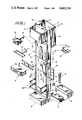
- FIG. 1is a perspective view, mainly from the front, of a free-standing type power column according to the present invention, with a variety of equipment and brackets depicted in exploded relationship;
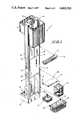
- FIG. 2is a view similar to FIG. 1, taken mainly from the rear of the service column;
- FIG. 3is a horizontal sectional view taken through the service column along line 3--3 of FIG. 1;
- FIG. 4is a plan view of a holder and locking slide element mounted in a track of the column;
- FIG. 5is a side elevational view, partly in vertical section, of the holder and locking slide
- FIG. 6is a side elevational view of the service column
- FIG. 7is a rear elevational view of the service column
- FIG. 8is a perspective view of a portion of a track of the service column depicting an enlarged portion of a track channel for receiving a locking slide element;
- FIG. 9is a front elevational view of a holder according to the present invention, with a mounting bracket disposed therein;
- FIG. 10is a side elevational view of the holder, partly in longitudinal section, depicting an expansible, contractable plug of the bracket in a retracted condition;
- FIG. 11is a view similar to FIG. 10, depicting the plug in an expanded condition to secure the bracket to the holder.
- a patient care service column 10comprises a pair of upstanding support pillars 12, 12A mounted on a support base 16.
- the basecomprises front and rear sections 18, 20 that project laterally outwardly from both sides of a vertical plane containing the two pillars 12, 12A.
- the columnis thus of the free-standing island type.
- Each pillar 12, 12A(FIG. 3) comprises front and rear sides 22, 24, an inward side 26, and an outward side 28 which are formed of extruded aluminum walls and suitable fastened together, by interlocking dovetail and filler rod.
- the chasesare vertically spaced and affixed to the pillars at various elevations by means of screw fasteners 31.
- a plurality of similar chases 32extend across the rear side of the column, i.e., from the rear side of one pillar to the rear side of the other pillar.
- the front and rear chasesare adapted to carry various services for a hospital patient such as outlets for gas, air oxygen, vacuum, telephone and/or electricity (line voltage, low voltage, emergency power, ground, etc.) for example, which is supplied from above (ceiling) or below (floor) via lines disposed interiorly of the column.
- Outletscan also be mounted along the outward sides 28 of both pillars. The particular provision and arrangement of the outlets will depend in large part upon the particular patient services desired by the hospital.
- the chases 30, 32are covered by sheet metal panels 34, 36, preferably of a decorative nature.
- the panelscontain openings which align with the various outlets to provide access to the latter. Since the chases 30, 32 and panels 34, 36 are formed of a non-flammable material, there is no need to position the electrical lines within metal conduits. This represents substantial savings in labor and materials, as well as in available interior space.
- the front and rear walls 22, 24are of mutually configuration as are inward and outward walls 26, 28.
- the outer wall 28includes an outwardly facing slot 37 adapted to slidingly receive a decorative side panel 38.
- Brackets 40Mounted on the front and rear walls 22, 24 are vertically oriented brackets 40 to which the chases are connected.
- Each bracket 40is of generally U-shaped configuration in cross-section, and includes lateral flanges 42, 44.
- One flange 42is attached, e.g., by screws 46, to the associated front or rear wall.
- the other flange 44is connected to the chases by the screws 31.
- the pillars 12, 12A and chases 30, 32enclose an interior space 50 through which pass the various fluid and electrical conduits 52 (FIG. 1).
- those conduitsextend upwardly through the ceiling and connect with standard fluid and electrical supply lines.
- the electrical wiresare connected to a main junction box 54 disposed at an upper end of the column. This junction box is also connected to the incoming electrical lines.
- the columncan be prewired, with the final hook-up being made by simply connecting-up the incoming electrical lines to the junction box.
- the latteralso serves as a support for various pieces of equipment such as, for example, a monitor (not shown, but mountable upon a bracket 58), elapsed time clock 60, lighting 62, suction bottles, nurse call, nurse workshelf 64 (FIG. 2), waste receptacle 66, sphygmomanometer 68, storage containers 70, infusion pump (not shown), etc. It is desirable that some or all of those pieces of equipment be mounted for rapid insertion, removal and/or adjustment of location so as to be adaptable to various patient requirements, especially in emergency situations.
- the track arrangementwhich affords adjustable mounting of a wide variety of equipment.
- the track arrangementcomprises four vertical tracks 76, 78, 80, 82 which are located at all four corners of the column and which extend the height of the column.
- Each trackis preferably formed of extruded aluminum and is mounted to a pillar by removable fasteners, such as screws 84.
- Each trackincludes flanges 86 which form a vertically oriented, horizontally open slot 88.
- the tracksare arranged such that the slot of each track faces the slot of the other track on the same side of the column (i.e., front side or back side).
- the spacing between adjacent slotsis dimensioned to enable the edges of the front and rear decorative metal panels 34, 36 to be received in the slots.
- Each trackalso forms a vertical channel 90 which is open outwardly along a portion of reduced width formed by two mutually opposing shoulders 92, 94.
- the channel 90is sized to adjustably receive a holder which is adapted to support an appropriate item.
- a preferred holder 102is depicted in FIGS. 4, 5 and 9-11. This holder is suitable for use in connection with any type of track and is not intended solely for use on a medical service column.
- the holder 102is adapted to support a piece of equipment, e.g., an infusion pump, for vertical as well as horizontal adjustment.
- the holderincludes a base portion 104 which is to be mounted for sliding movement along a channel 90 of the column, and a socket portion 106 adapted to receive a mounting arm to hold the piece of equipment.
- the base portion 104carries a slide lock assembly 100.
- the baseincludes a flange 108 and a pair of plates 110 extending outwardly therefrom. Each plate contains a window 112 which renders accessible the interior space between the plates 114.
- the slide lock assembly 100Attached to the flange 108 is the slide lock assembly 100 which enables the holder to be secured at different vertical locations along the channel 90.
- the slide lock assembly 100comprises a hollow tubular slide element 120 formed of a low-friction material such as plastic. In cross-section, the slide element 120 is slightly smaller than the channel 90 to allow a small degree of movement of the slide element therewithin.
- a rigid insert 122formed of metal, for example.
- the slide elementis attached to the insert by means of a rivet 124.
- Connecting the slide element to the flange 108are a pair of guide screws 111 and an adjustment screw 113.
- the guide screws 111extend freely through aligned oversized holes in the flange 108 and slide element 120 and are threadedly received in a threaded hole in the insert 122.
- the adjustment screw 113extends through aligned oversized holes in the flange 108 and slide element 120 and is threadedly received in the insert 122.
- a knob 126is attached to the adjustment screw 113 and is accessible to manual rotation through the windows 112 of the plates.
- a plastic spacer 128is loosely mounted on the adjustment screw and is disposed between the knob and the flange. As the knob 126 and adjustment screw 113 are rotated clockwise, the screw 113 progressively enters the respective hole in the insert 122, and the spacer 128 is drawn toward the flange 108. After the spacer 128 contacts the flange 108, further rotation of the adjustment screw 113 causes the insert 122 and also the slide element 120, to be drawn toward the flange whereupon the slide element contacts the shoulders 92, 94 of the channel 90 to retain the slide element 120, and thus the entire holder 102 at the given elevation along the channel 90.
- the guide screws 111guide the slide lock assembly in its movement toward and away from the flange.
- Insertion and removal of the slide lock assembly 100 relative to the channel 90is provided by one or more entry zones along each track. Those entry zones are in the form of enlargements 132 (FIG. 8) wherein the shoulders 92, 94 are absent. The enlargement 132 is wide enough to admit the slide element 120. Enlargements in adjacent tracks can be disposed at the same elevation to enable horizontal elements with locking slides at opposite ends to be inserted into the tracks.
- the socket 106is formed at the outer ends of the plates and has an open-ended bore 148 extending perpendicularly to the axis of the adjustment screw.
- a bracket 150has a tongue 152 which is insertable into the bore 148 in the direction of arrow A in FIG. 10.
- the tongueincludes a hollow cylindrical plug 154 formed of a relatively high friction material, such as rubber for example.
- the plug 154is secured to an ear 156 of the bracket 150 by means of a threaded fastener 158.
- the fastener 158includes a head 157 and a rod portion which passes through the plug 154. The rod portion is threaded at 159 and receives a threaded nut 160 and washer 162 at its outer end.
- bracket 150can be selectively secured within the holder 102.
- a stop ring 163can be secured to the fastener by means of a screw 165 to prevent inadvertent loss of the nut 160.
- the free end 166 of the bracketcan be arranged to receive any appropriate piece of equipment.
- the piece of equipmentcan be adjusted vertically along the channel 90 by means of the slide lock assembly 100, and adjusted laterally by loosening the plug 154 and swinging the bracket relative to the holder.
- the slide lock assemblycan be disposed on any suitable bracket or hanger upon which items or equipment are to be secured.
- a slide lock assembly 100is mounted on a hanger 170 in FIG. 1 which is suited for I.V. units.
- a locking slidecan be provided on different types of equipment or holders.
- a locking slidecan be provided at each end of a bumper guard 180 (FIG. 1) whereby one side can be mounted in one track at the front (or back) of the column, and the other slide can be mounted in the other track on that same side.
- the holder 102 according to the present inventionis suitable for use with any suitable type of track regardless of whether it is mounted on a column, wall, ceiling, floor, etc. That is, the utility of the holder is independent of the column.
- a track arrangementenables various pieces of equipment to be quickly and conveniently inserted and removed.
- equipmentcan be mounted virtually wherever it is most accessible for use or remote (for temporary storage).
- To install a pieceit is merely necessary to insert the locking slide into an enlargement of the channel 90, whereupon the slide can be slid upwardly or downwardly to any appropriate elevation.
- the provision of tracks at all four cornersenables horizontally extending elements having two sides to be mounted in two adjacent tracks.
- the locking slideenables the equipment to be locked or released for movement by the mere actuation of a threaded member.
- a holder carrying a movable armfurther enables the equipment to be adjusted in a horizontal direction, as well as in a vertical direction to the most appropriate location.
- the armis held in its various positions of horizontal adjustment by means of the resilient engagement between the arm and the resilient tongue.
- Differently configured mounting armscan be substituted for that depicted by merely pulling the tongue from the socket and inserting the tongue of the new arm into the socket.
- the channel enlargements of a given trackare vertically spaced in accordance with the vertical spacing between the locking slides of a vertically oriented holder, such as a U-shaped member 190 (FIG. 1) for holding the sphygmomanometer 68. This enables the slides of that member to be simultaneously introduced into the track.
- a vertically oriented holdersuch as a U-shaped member 190 (FIG. 1) for holding the sphygmomanometer 68.
Landscapes
- Engineering & Computer Science (AREA)
- Health & Medical Sciences (AREA)
- General Engineering & Computer Science (AREA)
- Life Sciences & Earth Sciences (AREA)
- Animal Behavior & Ethology (AREA)
- General Health & Medical Sciences (AREA)
- Public Health (AREA)
- Veterinary Medicine (AREA)
- Mechanical Engineering (AREA)
- Nursing (AREA)
- Biomedical Technology (AREA)
- Medical Preparation Storing Or Oral Administration Devices (AREA)
Abstract
Description
Claims (1)
Priority Applications (1)
| Application Number | Priority Date | Filing Date | Title |
|---|---|---|---|
| US06/806,428US4662524A (en) | 1983-01-31 | 1985-12-09 | Medical service column and mounting bracket |
Applications Claiming Priority (2)
| Application Number | Priority Date | Filing Date | Title |
|---|---|---|---|
| US06/462,682US4523683A (en) | 1983-01-31 | 1983-01-31 | Medical service column and mounting bracket |
| US06/806,428US4662524A (en) | 1983-01-31 | 1985-12-09 | Medical service column and mounting bracket |
Related Parent Applications (2)
| Application Number | Title | Priority Date | Filing Date |
|---|---|---|---|
| US06/462,682DivisionUS4523683A (en) | 1983-01-31 | 1983-01-31 | Medical service column and mounting bracket |
| US06/613,204DivisionUS4574963A (en) | 1983-01-31 | 1984-05-23 | Medical service column and mounting bracket |
Publications (1)
| Publication Number | Publication Date |
|---|---|
| US4662524Atrue US4662524A (en) | 1987-05-05 |
Family
ID=27040419
Family Applications (1)
| Application Number | Title | Priority Date | Filing Date |
|---|---|---|---|
| US06/806,428Expired - LifetimeUS4662524A (en) | 1983-01-31 | 1985-12-09 | Medical service column and mounting bracket |
Country Status (1)
| Country | Link |
|---|---|
| US (1) | US4662524A (en) |
Cited By (31)
| Publication number | Priority date | Publication date | Assignee | Title |
|---|---|---|---|---|
| US5284254A (en)* | 1992-06-24 | 1994-02-08 | B-Line Systems, Inc. | Rack for electrical equipment |
| US5307942A (en)* | 1991-11-29 | 1994-05-03 | Alcatel Cit | Electronic, especially telecommunication equipment rack |
| US5323916A (en)* | 1992-12-23 | 1994-06-28 | Newton Instrument Company, Inc. | Unequal flange-type telephone equipment rack adapted for universal application |
| US5537289A (en)* | 1994-03-11 | 1996-07-16 | Spacelabs Medical, Inc. | Wall-mounted medical monitoring system with removable modules |
| US6006925A (en)* | 1997-06-03 | 1999-12-28 | Hendry Mechanical Works | Equipment rack system |
| USD418603S (en)* | 1998-06-26 | 2000-01-04 | Hill-Rom, Inc. | Power column |
| US6096025A (en)* | 1997-11-07 | 2000-08-01 | Hill-Rom, Inc. | Mobile surgical support apparatus |
| US6481582B1 (en) | 2001-06-04 | 2002-11-19 | Cooper Technologies Company | Rack |
| US6517174B2 (en) | 1998-06-23 | 2003-02-11 | Hendry Telephone Products | Equipment mounting racks and cabinets |
| US6561602B1 (en) | 1998-06-23 | 2003-05-13 | Hendry Mechanical Works | Equipment mounting racks and cabinets |
| US6725483B2 (en) | 1997-01-31 | 2004-04-27 | Hill-Rom Services, Inc. | Apparatus and method for upgrading a hospital room |
| US20040232286A1 (en)* | 2003-03-18 | 2004-11-25 | Newkirk David C. | Patient line management system |
| US20040237202A1 (en)* | 2001-05-25 | 2004-12-02 | Gallant Dennis J. | Architectural system adaptable to patient acuity level |
| US20070126318A1 (en)* | 2004-10-14 | 2007-06-07 | Hamberg Stephen R | Service head with accessory tracks |
| US20100095604A1 (en)* | 2008-10-16 | 2010-04-22 | Newkirk David C | Modular Architectural Room System |
| EP1629746A3 (en)* | 2004-08-25 | 2010-06-30 | TRILUX-LENZE GmbH + Co. KG | Supply unit with attachable furniture elements |
| US8051610B2 (en) | 2004-09-22 | 2011-11-08 | Hill-Rom Services, Inc. | Patient flatwall system |
| EP2463874A1 (en)* | 2010-12-13 | 2012-06-13 | Coactive Technologies, LLC | Control console for a medical apparatus, the console being mountable on a rail |
| USD687148S1 (en)* | 2010-09-03 | 2013-07-30 | Welch Allyn, Inc. | Medical device basket |
| US8522488B1 (en) | 2012-10-15 | 2013-09-03 | Hill-Rom Services, Inc. | Headwall with integral wall panel interface |
| USD689194S1 (en)* | 2010-03-24 | 2013-09-03 | Welch Allyn, Inc. | Medical-stand bins |
| US20140175031A1 (en)* | 2012-12-21 | 2014-06-26 | Nathan R. Roberts | Storage and charging station system for portable electronic devices |
| US20150041419A1 (en)* | 2012-04-23 | 2015-02-12 | Terumo Kabushiki Kaisha | Medical apparatus rack |
| US20150076311A1 (en)* | 2012-04-02 | 2015-03-19 | Sms Smart Media Solutions Ab | Height adjustable stand for screen or display |
| EP3135264A1 (en)* | 2015-08-22 | 2017-03-01 | Hunan Taiyanglong Medical Tech., Co., Ltd. | An integrated nursing system used in a ward |
| US9680317B2 (en) | 2012-12-21 | 2017-06-13 | Nathan R. Roberts | Storage and charging station system for portable electronic devices |
| US10076050B2 (en) | 2012-12-21 | 2018-09-11 | Nathan R. Roberts | Storage and charging station system for portable electronic devices |
| US10312700B2 (en)* | 2012-12-21 | 2019-06-04 | Nathan R. Roberts | Storage and charging station system for portable electronic devices |
| US10432001B1 (en)* | 2018-05-29 | 2019-10-01 | Vanessa Bellis | Stackable shelf system for charging electrical devices |
| US10638630B2 (en)* | 2012-12-21 | 2020-04-28 | Nathan R. Roberts | Storage and charging station system for portable electronic devices with side access to power distribution components |
| US10849705B1 (en)* | 2019-04-06 | 2020-12-01 | Steven LaBua | Storage rack for use with a medical slide bracket for holding and supporting accessory articles |
Citations (17)
| Publication number | Priority date | Publication date | Assignee | Title |
|---|---|---|---|---|
| DE262559C (en)* | ||||
| US755668A (en)* | 1903-11-28 | 1904-03-29 | Joseph H Hurxthal | Mirror-support. |
| FR631300A (en)* | 1927-03-23 | 1927-12-17 | A C A M Soc D Applic Commercia | Display rack |
| US2129933A (en)* | 1936-11-13 | 1938-09-13 | Airmaster Corp | Mounting for air circulator devices |
| US2336044A (en)* | 1943-05-20 | 1943-12-07 | Wellman Co | Locking mechanism |
| DE840380C (en)* | 1947-06-11 | 1952-06-03 | Marthe Marie Louise Martin Bin | Handle attachment for striking tools |
| US3050194A (en)* | 1960-04-28 | 1962-08-21 | Senn Custom Inc | Rack assembly |
| GB976189A (en)* | 1963-10-31 | 1964-11-25 | Derek William Gould | Improvements in means for the stacking and dispensing of articles |
| GB1021879A (en)* | 1963-12-24 | 1966-03-09 | Hille & Company Ltd S | Improvements in and relating to wall brackets |
| GB1188743A (en)* | 1968-07-02 | 1970-04-22 | Joseph Chak-Fai Chiu | Constructional Systems for Shelving. |
| GB1207891A (en)* | 1968-02-01 | 1970-10-07 | Standard Telephones Cables Ltd | Improvements in or relating to connections between structural members particularly for racks for electrical equipment |
| US4045980A (en)* | 1976-07-06 | 1977-09-06 | Rexnord Inc. | Retainer for slip sleeve liners |
| US4158511A (en)* | 1977-09-28 | 1979-06-19 | Trw Inc. | Pivot joint |
| USD261804S (en) | 1979-01-17 | 1981-11-10 | Hill-Rom Company, Inc. | Columnar patient care service facility |
| GB2082893A (en)* | 1980-09-02 | 1982-03-17 | Doveline Timber Display System | Shelving brackets |
| EP0048225A2 (en)* | 1980-09-17 | 1982-03-24 | MOVI S.n.c. | An assembly for fixing an article of furniture to adjacent wooden panels on a wall |
| US4523683A (en)* | 1983-01-31 | 1985-06-18 | Hill-Rom Company, Inc. | Medical service column and mounting bracket |
- 1985
- 1985-12-09USUS06/806,428patent/US4662524A/ennot_activeExpired - Lifetime
Patent Citations (17)
| Publication number | Priority date | Publication date | Assignee | Title |
|---|---|---|---|---|
| DE262559C (en)* | ||||
| US755668A (en)* | 1903-11-28 | 1904-03-29 | Joseph H Hurxthal | Mirror-support. |
| FR631300A (en)* | 1927-03-23 | 1927-12-17 | A C A M Soc D Applic Commercia | Display rack |
| US2129933A (en)* | 1936-11-13 | 1938-09-13 | Airmaster Corp | Mounting for air circulator devices |
| US2336044A (en)* | 1943-05-20 | 1943-12-07 | Wellman Co | Locking mechanism |
| DE840380C (en)* | 1947-06-11 | 1952-06-03 | Marthe Marie Louise Martin Bin | Handle attachment for striking tools |
| US3050194A (en)* | 1960-04-28 | 1962-08-21 | Senn Custom Inc | Rack assembly |
| GB976189A (en)* | 1963-10-31 | 1964-11-25 | Derek William Gould | Improvements in means for the stacking and dispensing of articles |
| GB1021879A (en)* | 1963-12-24 | 1966-03-09 | Hille & Company Ltd S | Improvements in and relating to wall brackets |
| GB1207891A (en)* | 1968-02-01 | 1970-10-07 | Standard Telephones Cables Ltd | Improvements in or relating to connections between structural members particularly for racks for electrical equipment |
| GB1188743A (en)* | 1968-07-02 | 1970-04-22 | Joseph Chak-Fai Chiu | Constructional Systems for Shelving. |
| US4045980A (en)* | 1976-07-06 | 1977-09-06 | Rexnord Inc. | Retainer for slip sleeve liners |
| US4158511A (en)* | 1977-09-28 | 1979-06-19 | Trw Inc. | Pivot joint |
| USD261804S (en) | 1979-01-17 | 1981-11-10 | Hill-Rom Company, Inc. | Columnar patient care service facility |
| GB2082893A (en)* | 1980-09-02 | 1982-03-17 | Doveline Timber Display System | Shelving brackets |
| EP0048225A2 (en)* | 1980-09-17 | 1982-03-24 | MOVI S.n.c. | An assembly for fixing an article of furniture to adjacent wooden panels on a wall |
| US4523683A (en)* | 1983-01-31 | 1985-06-18 | Hill-Rom Company, Inc. | Medical service column and mounting bracket |
Cited By (44)
| Publication number | Priority date | Publication date | Assignee | Title |
|---|---|---|---|---|
| US5307942A (en)* | 1991-11-29 | 1994-05-03 | Alcatel Cit | Electronic, especially telecommunication equipment rack |
| US5284254A (en)* | 1992-06-24 | 1994-02-08 | B-Line Systems, Inc. | Rack for electrical equipment |
| US5323916A (en)* | 1992-12-23 | 1994-06-28 | Newton Instrument Company, Inc. | Unequal flange-type telephone equipment rack adapted for universal application |
| US5537289A (en)* | 1994-03-11 | 1996-07-16 | Spacelabs Medical, Inc. | Wall-mounted medical monitoring system with removable modules |
| US6725483B2 (en) | 1997-01-31 | 2004-04-27 | Hill-Rom Services, Inc. | Apparatus and method for upgrading a hospital room |
| US20050017468A1 (en)* | 1997-01-31 | 2005-01-27 | Gallant Dennis J. | Apparatus and method for upgrading a hospital room |
| US6006925A (en)* | 1997-06-03 | 1999-12-28 | Hendry Mechanical Works | Equipment rack system |
| US6096025A (en)* | 1997-11-07 | 2000-08-01 | Hill-Rom, Inc. | Mobile surgical support apparatus |
| US6517174B2 (en) | 1998-06-23 | 2003-02-11 | Hendry Telephone Products | Equipment mounting racks and cabinets |
| US6527351B1 (en) | 1998-06-23 | 2003-03-04 | Hendry Mechanical Works | Equipment mounting racks and cabinets |
| US6561602B1 (en) | 1998-06-23 | 2003-05-13 | Hendry Mechanical Works | Equipment mounting racks and cabinets |
| USD418603S (en)* | 1998-06-26 | 2000-01-04 | Hill-Rom, Inc. | Power column |
| US20040237202A1 (en)* | 2001-05-25 | 2004-12-02 | Gallant Dennis J. | Architectural system adaptable to patient acuity level |
| US7219472B2 (en) | 2001-05-25 | 2007-05-22 | Hill-Rom Services, Inc. | Ceiling-mounted overbed table |
| US7040057B2 (en) | 2001-05-25 | 2006-05-09 | Hill-Rom Services, Inc. | Architectural system adaptable to patient acuity level |
| US6481582B1 (en) | 2001-06-04 | 2002-11-19 | Cooper Technologies Company | Rack |
| US20040232286A1 (en)* | 2003-03-18 | 2004-11-25 | Newkirk David C. | Patient line management system |
| US7083150B2 (en) | 2003-03-18 | 2006-08-01 | Hill-Rom Services, Inc. | Patient line management system |
| EP1629746A3 (en)* | 2004-08-25 | 2010-06-30 | TRILUX-LENZE GmbH + Co. KG | Supply unit with attachable furniture elements |
| US8051610B2 (en) | 2004-09-22 | 2011-11-08 | Hill-Rom Services, Inc. | Patient flatwall system |
| US8678334B2 (en) | 2004-09-22 | 2014-03-25 | Hill-Rom Services, Inc. | Patient flatwall system |
| US20070126318A1 (en)* | 2004-10-14 | 2007-06-07 | Hamberg Stephen R | Service head with accessory tracks |
| US20100095604A1 (en)* | 2008-10-16 | 2010-04-22 | Newkirk David C | Modular Architectural Room System |
| US10159616B2 (en) | 2008-10-16 | 2018-12-25 | Wittrock Enterprises Llc | Modular wall for dividing rooms in a healthcare facility |
| US8640391B2 (en) | 2008-10-16 | 2014-02-04 | Hill-Rom Services, Inc. | Modular architectural room system |
| USD689194S1 (en)* | 2010-03-24 | 2013-09-03 | Welch Allyn, Inc. | Medical-stand bins |
| USD687148S1 (en)* | 2010-09-03 | 2013-07-30 | Welch Allyn, Inc. | Medical device basket |
| EP2463874A1 (en)* | 2010-12-13 | 2012-06-13 | Coactive Technologies, LLC | Control console for a medical apparatus, the console being mountable on a rail |
| CN102551768A (en)* | 2010-12-13 | 2012-07-11 | 联合活跃技术有限责任公司 | Rail-mountable control console for a medical apparatus |
| US20120148335A1 (en)* | 2010-12-13 | 2012-06-14 | CoActive Technologies, LLC | Rail-Mountable Control Console For A Medical Apparatus |
| US20150076311A1 (en)* | 2012-04-02 | 2015-03-19 | Sms Smart Media Solutions Ab | Height adjustable stand for screen or display |
| US9169960B2 (en)* | 2012-04-02 | 2015-10-27 | Sms Smart Media Solutions Ab | Height adjustable stand for screen or display |
| US9808316B2 (en)* | 2012-04-23 | 2017-11-07 | Terumo Kabushiki Kaisha | Medical apparatus rack |
| US20150041419A1 (en)* | 2012-04-23 | 2015-02-12 | Terumo Kabushiki Kaisha | Medical apparatus rack |
| US8522488B1 (en) | 2012-10-15 | 2013-09-03 | Hill-Rom Services, Inc. | Headwall with integral wall panel interface |
| US9680317B2 (en) | 2012-12-21 | 2017-06-13 | Nathan R. Roberts | Storage and charging station system for portable electronic devices |
| US10076050B2 (en) | 2012-12-21 | 2018-09-11 | Nathan R. Roberts | Storage and charging station system for portable electronic devices |
| US10084327B2 (en)* | 2012-12-21 | 2018-09-25 | Nathan R. Roberts | Storage and charging station system for portable electronic devices |
| US20140175031A1 (en)* | 2012-12-21 | 2014-06-26 | Nathan R. Roberts | Storage and charging station system for portable electronic devices |
| US10312700B2 (en)* | 2012-12-21 | 2019-06-04 | Nathan R. Roberts | Storage and charging station system for portable electronic devices |
| US10638630B2 (en)* | 2012-12-21 | 2020-04-28 | Nathan R. Roberts | Storage and charging station system for portable electronic devices with side access to power distribution components |
| EP3135264A1 (en)* | 2015-08-22 | 2017-03-01 | Hunan Taiyanglong Medical Tech., Co., Ltd. | An integrated nursing system used in a ward |
| US10432001B1 (en)* | 2018-05-29 | 2019-10-01 | Vanessa Bellis | Stackable shelf system for charging electrical devices |
| US10849705B1 (en)* | 2019-04-06 | 2020-12-01 | Steven LaBua | Storage rack for use with a medical slide bracket for holding and supporting accessory articles |
Similar Documents
| Publication | Publication Date | Title |
|---|---|---|
| US4523683A (en) | Medical service column and mounting bracket | |
| US4662524A (en) | Medical service column and mounting bracket | |
| US4574963A (en) | Medical service column and mounting bracket | |
| US4646211A (en) | Service outlet wall and rail system for use thereon | |
| US4338485A (en) | Headwall unit for patient servicing and method for installation | |
| US6220186B1 (en) | Modular interior furnishing system | |
| US5022720A (en) | Display case | |
| JP2569281Y2 (en) | Modular office furniture | |
| CA2310869C (en) | Wall system | |
| US20100205868A1 (en) | Office system | |
| US4354330A (en) | Flat-cornered triangular medical column | |
| US6726034B2 (en) | Furniture system | |
| US4753055A (en) | Headwall unit for hospital rooms and the like | |
| US20020033372A1 (en) | Display system for death care merchandise | |
| US4415957A (en) | Patient light with hanger and hinge arrangement for removal without tools | |
| CA2238536A1 (en) | Hybrid office panel construction for a modular office furniture system | |
| EP3766381A1 (en) | System for mounting, accessing, moving and folding away articles on, under or along a surface | |
| US4941071A (en) | Quick mounting arrangement for light fixtures in overhead cabinets and the like | |
| DE69316247D1 (en) | Work room partition system | |
| GB1460321A (en) | Furniture systems | |
| US7267305B2 (en) | Carrying device having tubular member for supply lines | |
| WO2022104093A2 (en) | Floating fixture wall mount system and method of use | |
| US4126971A (en) | Fixture hanging assembly | |
| US5713657A (en) | Indirect lighting system | |
| EP1680976A1 (en) | Modular equipped wall |
Legal Events
| Date | Code | Title | Description |
|---|---|---|---|
| FEPP | Fee payment procedure | Free format text:PAYOR NUMBER ASSIGNED (ORIGINAL EVENT CODE: ASPN); ENTITY STATUS OF PATENT OWNER: LARGE ENTITY | |
| STCF | Information on status: patent grant | Free format text:PATENTED CASE | |
| FPAY | Fee payment | Year of fee payment:4 | |
| FEPP | Fee payment procedure | Free format text:PAYER NUMBER DE-ASSIGNED (ORIGINAL EVENT CODE: RMPN); ENTITY STATUS OF PATENT OWNER: LARGE ENTITY Free format text:PAYOR NUMBER ASSIGNED (ORIGINAL EVENT CODE: ASPN); ENTITY STATUS OF PATENT OWNER: LARGE ENTITY | |
| FEPP | Fee payment procedure | Free format text:PAYOR NUMBER ASSIGNED (ORIGINAL EVENT CODE: ASPN); ENTITY STATUS OF PATENT OWNER: LARGE ENTITY Free format text:PAYER NUMBER DE-ASSIGNED (ORIGINAL EVENT CODE: RMPN); ENTITY STATUS OF PATENT OWNER: LARGE ENTITY | |
| FPAY | Fee payment | Year of fee payment:8 | |
| FEPP | Fee payment procedure | Free format text:PAYOR NUMBER ASSIGNED (ORIGINAL EVENT CODE: ASPN); ENTITY STATUS OF PATENT OWNER: LARGE ENTITY Free format text:PAYER NUMBER DE-ASSIGNED (ORIGINAL EVENT CODE: RMPN); ENTITY STATUS OF PATENT OWNER: LARGE ENTITY | |
| FPAY | Fee payment | Year of fee payment:12 | |
| AS | Assignment | Owner name:HILL-ROM SERVICES, INC., INDIANA Free format text:ASSIGNMENT OF ASSIGNORS INTEREST;ASSIGNOR:HILL-ROM, INC.;REEL/FRAME:011796/0440 Effective date:20010215 |