US4662252A - Auto-grip pliers - Google Patents
Auto-grip pliersDownload PDFInfo
- Publication number
- US4662252A US4662252AUS06/777,358US77735885AUS4662252AUS 4662252 AUS4662252 AUS 4662252AUS 77735885 AUS77735885 AUS 77735885AUS 4662252 AUS4662252 AUS 4662252A
- Authority
- US
- United States
- Prior art keywords
- pliers
- handle member
- handle
- linking arm
- members
- Prior art date
- Legal status (The legal status is an assumption and is not a legal conclusion. Google has not performed a legal analysis and makes no representation as to the accuracy of the status listed.)
- Expired - Lifetime
Links
- 230000009471actionEffects0.000claimsdescription13
- 230000004044responseEffects0.000claimsdescription6
- 210000003813thumbAnatomy0.000claimsdescription3
- 230000000284resting effectEffects0.000claims1
- 238000004519manufacturing processMethods0.000abstract1
- 239000002184metalSubstances0.000description5
- 238000010276constructionMethods0.000description4
- 238000005242forgingMethods0.000description3
- 125000006850spacer groupChemical group0.000description3
- 239000007787solidSubstances0.000description2
- 229910000831SteelInorganic materials0.000description1
- 230000001154acute effectEffects0.000description1
- 230000008901benefitEffects0.000description1
- 230000015572biosynthetic processEffects0.000description1
- 239000000470constituentSubstances0.000description1
- 210000003811fingerAnatomy0.000description1
- 229920002457flexible plasticPolymers0.000description1
- 230000003993interactionEffects0.000description1
- 239000002650laminated plasticSubstances0.000description1
- 239000000463materialSubstances0.000description1
- 238000000034methodMethods0.000description1
- 230000037361pathwayEffects0.000description1
- 229920003023plasticPolymers0.000description1
- 238000003825pressingMethods0.000description1
- 238000007493shaping processMethods0.000description1
- 239000010959steelSubstances0.000description1
- XLYOFNOQVPJJNP-UHFFFAOYSA-NwaterSubstancesOXLYOFNOQVPJJNP-UHFFFAOYSA-N0.000description1
Images


Classifications
- B—PERFORMING OPERATIONS; TRANSPORTING
- B25—HAND TOOLS; PORTABLE POWER-DRIVEN TOOLS; MANIPULATORS
- B25B—TOOLS OR BENCH DEVICES NOT OTHERWISE PROVIDED FOR, FOR FASTENING, CONNECTING, DISENGAGING OR HOLDING
- B25B7/00—Pliers; Other hand-held gripping tools with jaws on pivoted limbs; Details applicable generally to pivoted-limb hand tools
- B25B7/12—Pliers; Other hand-held gripping tools with jaws on pivoted limbs; Details applicable generally to pivoted-limb hand tools involving special transmission means between the handles and the jaws, e.g. toggle levers, gears
- B—PERFORMING OPERATIONS; TRANSPORTING
- B25—HAND TOOLS; PORTABLE POWER-DRIVEN TOOLS; MANIPULATORS
- B25B—TOOLS OR BENCH DEVICES NOT OTHERWISE PROVIDED FOR, FOR FASTENING, CONNECTING, DISENGAGING OR HOLDING
- B25B7/00—Pliers; Other hand-held gripping tools with jaws on pivoted limbs; Details applicable generally to pivoted-limb hand tools
- B25B7/06—Joints
- B25B7/10—Joints with adjustable fulcrum
- B—PERFORMING OPERATIONS; TRANSPORTING
- B25—HAND TOOLS; PORTABLE POWER-DRIVEN TOOLS; MANIPULATORS
- B25B—TOOLS OR BENCH DEVICES NOT OTHERWISE PROVIDED FOR, FOR FASTENING, CONNECTING, DISENGAGING OR HOLDING
- B25B7/00—Pliers; Other hand-held gripping tools with jaws on pivoted limbs; Details applicable generally to pivoted-limb hand tools
- B25B7/14—Locking means
- B25B7/16—Locking means combined with means for tightening the operating arms of jaws
Definitions
- This inventionpertains generally to utility pliers of the type generally referred to as water pump pliers or slip-joint pliers, and more particularly pertains to utility pliers of the slip-joint type which are adapted to automatically self-adjust to the size of any work piece within the range of the jaws of the pliers by a one-hand operation.
- pliershave the common characteristic of jaws offset at an angle to the plier handles and a pivot post, in the form of a bolt or rivet, mounted in the area rearward of the jaw on one of the handles and projecting through an elongated slot on the other handle.
- means for enabling selective spacing of the distance between the jawsis variously provided by spaced-apart ridges or teeth along the inside long edge of the slot adapted for selective binding engagement with the pivot post.
- Another well-known method of providing distance adjustment between the jaws in such pliersis the provision of spaced-apart arcuate ridges on the interfacing surfaces adjacent the pivot point.
- Self-adjusting utility pliersare disclosed in pending U.S. patent application Ser. No. 654,405 filed Sept. 26, 1984, now U.S. Pat. No. 4,651,598; issued Mar. 24, 1987.
- the tool therein disclosedis intended for the same use and purpose as the aforedescribed prior art pliers but has the clear advantage of single-handed adjustment.
- the pliersare adapted to slideably close upon a work piece in response to manual closing action on the handles, and, in response to contact with the work piece, automatically lock against further sliding action and shift from the sliding to a pivoting mode whereby continued exertion of manual force on the handles causes increased gripping action on the work piece.
- the typical prior art slip-joint pliers which require two-handed adjustment, as heretofore described,are usually massproduced by a drop forging operation, the handle members are solid metal, and the area of connection between the two handle members is relatively planar and thin, whereas the gripping jaws are laterally inwardly widened to provide gripping surfaces which overlap into the plane of the center point of the axis of the pliers' interconnecting pivot.
- the aforementioned self-adjusting utility pliersalso are most easily adaptable to a substantially solid handle member construction obtainable through a forging operation.
- the present inventionrelated to utility pliers having the capability of automatic self-adjustment, and more particularly pertains to alternative improved constructions for such pliers.
- pliers of the typehaving a pair of pivotally connected first and second handle members with opposed gripping jaws and slot means in the first handle member enabling it to be slid relative to a pivot element projecting into the slot from the second handle member to vary the distance between the jaws
- pliersinclude biasing means operatively connecting the handle members and adapted to normally urge the handle the handle members to slide relative to each other whereby the jaws are disposed to their widest open position
- the biasing meansincludes a linking arm and at least one spring totally contained within the first handle member.
- the linking arminterconnects the handle members at their neck portions or a position generally intermediate the distance between the extreme outer ends or distal ends of the handle members and the pivot element which joins the handle members.
- the linking armhas its first end pivotally secured to the second handle member and its second end pivotably and slideably secured to the first handle member.
- the second end of the linking armis adapted to slide longitudinally a distance along a predetermined path which constitutes an inwardly facing linear slot in the first handle member.
- the spring disposed within the first handle memberinterconnects the second end of the linking arm with a point in the throat area of the second handle member which is closely adjacent the pivot element.
- a fixed stopis provided on the first handle member and marks the end of the predetermined path which is further from the distal end of the handle member and toward the pivot element.
- the linking armis adapted to pivot relative to the stop and respond to the pulling force of the spring so that the linking arm translates such pulling force to the second handle member as a force generally in a direction toward the distal end of the second handle member whereby the jaws are caused to normally slide to a fully open position.
- the improved pliers in accordance with both alternative structures or embodiments herein disclosedinclude a throat area or portion on the first handle member constituting rigid spacedapart and parallel sections. Each such section is provided with an elongated slot, and the throat area of the second handle member is disposed between the sections whereby the pivot element interconnecting the handle members projects laterally on opposite sides of the second handle member and extends through the slot in each section.
- the pivot elementis adapted to engage, along portions of the first handle member defining respective long edges of the slots, in response to a work piece disposed between the jaws and manual force being exerted against the handle members to move the jaws against the work piece.
- the preferred means of engaging the pivot element with the long edges of the slotsis the provision of successive teeth along the slot edge into which a rotatable pawl can interlock by engagement with adjacent pairs of teeth.
- a separate pawlis operatively associated with each longitudinal slot, and each pawl is designed to track and cam within the slot during use of the pliers as will be hereafter described in greater detail.
- a unique pivot elementconstituting a disc-shaped member having a integral pawl formed on each of its opposite faces, and the element is carried for rotation within a circular opening provided in the throat area of the second handle member.
- Another feature of both of the preferred embodiments disclosed hereinis the provision of manually operable means for releasably locking the handle members, and hence their jaws, in a fully closed or predetermined open disposition.
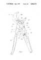
- FIG. 1is a side elevational view of a first presently preferred embodiment of the improved auto-grip pliers in accordance with the present invention
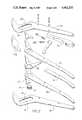
- FIG. 2is an exploded or perspective assembly layout of the constituent parts of the embodiment first shown in FIG. 1;
- FIG. 3is a side elevational view of an alternate or second presently preferred embodiment of improved auto-grip pliers in accordance with the present invention
- FIG. 4is a sectional view taken along lines IV--IV of FIG. 3;
- FIG. 5is a pattern layout illustrating how one or more of the handle members of an alternate embodiment of the invention may be stamped from a flat metal sheet for forming thereafter to the configuration of a handle;
- FIG. 6is a frangmentary isometric view of an alternative tooth and pawl arrangement usable in either embodiment of the invention herein disclosed.
- FIG. 1there is shown one presently preferred embodiment of pliers in accordance with the present invention.
- the pliers shown in FIG. 1comprise a first handle member 10 which coacts with a second handle member 12, as will be hereafter described.
- the handle member 10is made substantially from flat sheet steel parts laminated together to form a rigid whole.
- FIG. 2shows that the handle member 10 is comprised of rigid planar members 10a and 10b which are assembled with spacers 10c and 10d therebetween.
- the spacer 10cmay be formed from any suitable rigid lightweight plastic material, with an outer surface as shown in FIG. 1, to present a hand gripping surface in the use of the tool.
- Spacer 10dis cut from metal bar stock and serves as an inside laminate between the parts 10a and 10b to form the jaw end 14 of the handle member 10 as shown in FIG. 1.
- Each of the parts 10a and 10bare provided with identical elongated slots 16 and 18 having, along one long edge thereof, respective toothed racks 16a and 18a, each made up of a series of successive identical sized teeth providing spaces therebetween.
- the second handle member 12is similarly constructed from laminated flat parts, as shown in FIG. 2, which includes elongated planar parts 12a and 12b, a separator 12c, a jaw end separator 12d, and outside jaw portions 12e and 12f. All of the foregoing parts are suitably pinned to form the rigid second handle member 12.
- the jaw end 20 of handle member 12, as shown in FIG. 1,is formed when the parts 12a and 12b (FIG. 2) are united with the separating parts 12c and 12d properly aligned therebetween, and the wedged shaped parts 12e and 12f are fastened, in the same joining operation, to the respective outside jaw end surfaces of the parts 12a and 12b.
- the second handle member 12in its throat portion, which is rearward of the jaw 20, is pivotably and slideably secured between the parts 10a and 10b of the first handle member 10 whereby the slot 16 is on one side of the throat portion of the handle member 12 and the slot 18 is on the other side of the throat portion.
- a circular opening 22, as shown in FIG. 1,is provided through the throat area of the second handle member 12, and contained within the opening is a disc-shaped element 24 (see FIG. 2) having an integral pawl 24a on the face thereof which is visible on both FIGS. 1 and 2.
- An identical pawl(not shown) is provided on the opposite face of the element 24 whereby the element 24 has oppositely facing identical pawls for operative interaction with the respective toothed racks 16a and 18a.
- FIGS. 1illustrates that the handle members 10 and 12 are interconnected by a crossover linking arm 25.
- the linking arm 25is a rigid planar part having a first end 25a hidden from sight by disposition between parts 12a and 12b.
- the linking arm 25has a second end 25b disposed between parts 10a and 10b of handle 10.
- the end 25bnormally rides against a stop 26 in view of the pulling force of a spring 28 which interconnects the end 25b and a triangular extension of part 12d which is the center laminate of handle member 12.
- a second spring member 30interconnects the end 25b with a stationary pin 32 on the handle member 10, for a purpose hereafter described.
- a flexible plastic sleeve 34which can be designed to blend in color and shape with the plastic laminate 10c to create a comfortable hand hold for the user of the pliers.
- FIG. 3illustrates an alternate or second presently preferred embodiment of the disclosed invention, showing pliers disposed in a fully closed position and further, illustrating in phantom outline, the disposition of one of the handle members and certain related components of the pliers when a large item such as a piece of pipe is grasped between the jaws.
- the pliers in FIG. 3comprise a first handle member 40 and a second handle member 42.
- the pivotal connection between the handle membersis substantially the same as disclosed herein with reference to the embodiment shown in FIG. 1, utilizing the disc-shaped pivot element 24 as shown in FIG. 2.
- the respective handle members 40 and 42have opposed gripping jaws 44 and 46, and handle ends 48 and 50.
- a slot meansis provided in the first handle member 40 and comprises spaced apart identical elongated slots between which extends the throat area of the second handle member 42.
- FIG. 5illustrates handle 40 as it appears prior to being formed to the shape shown in FIG. 3.
- the handle 40is stamped, in the pattern configuration shown in FIG. 5, from a relatively thin metal sheet in which slots 40a and 40b are provided.
- Aperture 40c and 40dare provided to accommodate, after formation of the blank into the configuration shown in FIG. 3, a stationary pin 52 which serves as a stop for a purpose hereinafter described.
- FIG. 5also shows, at the handle end of the blank, edge portions 40e and 40f which will abut when the pressing operation is completed to turn the blank into the shape shown in FIG. 3, whereby the long outer edges of the pattern shown in FIG. 5 above the area of the portions 40e and 40f will be spaced a short distance apart to form a slot or sliding path, as shown in FIG. 3, for a linking arm 54.
- the linking arm 54has a first end 54a pivotably connected within a longitudinal inwardly facing slot in the handle member 42.
- a second end 54b of the linking arm 54is disposed within the handle member 40 and is connected by a coil tension spring 56 to the underside of the throat area of handle member 42.
- the end 54b of the linking arm 54is adapted to slide, during operation of the pliers, in a predetermined pathway which extends from the stop 52 toward the handle end 48 of the handle member 40.
- Carried within the handle memberis a leaf spring 58 fastened at one end to the handle by a rivet 60. The leaf spring 58 is temporarily deformable by downward sliding action of the end 54b of the link 54 whereby a slight upward pressure is constantly applied against the end 54b.
- the releasable locking meansShown on the handle member 42 and also in FIG. 4 is a releasable locking means to enable the user of the pliers to selectively temporarily lock the handles, and hence the jaws of the pliers, in a fully closed or partially closed position.
- the releasable locking meansdenoted by the number 62 is located coincidental with a short longitudinally extending slot on the back side of the handle 42 and includes an inside wedge portion 62a which is connected, by pins through the slot, to an outside button portion 62b.
- the button 62bis adapted for thumb operation whereby the user of the tool can slide it toward the jaw end thereof and cause the wedge portion 62a to move into contact with the end 54a of the linking arm 54 and exert a binding pressure thereagainst to lock the linking arm against pivoting action until the button 62b is actuated to move the wedge 62a away from contact with the linking arm and 54a.
- FIGS. 1 and 3The operation of the two embodiments of the pliers shown in FIGS. 1 and 3 is substantially identical, so description herein of the function is primarily with respect to the embodiment shown in FIG. 1, however, slight differences in the function of the pliers shown in FIG. 3 as compared to the embodiment of FIG. 1, will be hereafter specifically explained.
- the normal disposition of the pliersis a full open jaw disposition.
- Manipulation of the pliers to grip a work pieceis accomplished by the user holding the pliers in one hand and closing the thumb and fingers about the handle ends 10 and 12.
- the pliersare positioned whereby the jaw ends 14 and 20 have the selected work piece therebetween, and squeezing of the user's hand causes the handle members to move inwardly whereby jaw 20 is caused to move toward jaw 14 until the work piece is contacted therebetween.
- This actioncauses a slight pivoting motion of the handle 12 on the pivot element 24, counter-clockwise as viewed in FIG.
- FIG. 3The operation of the embodiment of the pliers as shown in FIG. 3 is substantially as heretofore described, except that the second coiled tension spring 30 shown in FIG. 1 is eliminated and, in this embodiment, a deformable leaf spring 58 is provided in the space in the distal end of the handle member 40 to provide resistance against the end 54b of the linking arm 54 and thereby exert a pushing force linearly through the linking arm 54 to the pivot point 54a on the handle member 42.
- FIG. 6illustrates this feature, wherein throat area handle sections 70 and 72 are shown in spaced-apart disposition.
- the section 70is provided with a slot 74 and the section 72 is provided with a slot 76. While the slots 74 and 76 are in alignment, the rack of teeth in one slot is offset relative to the rack of teeth in the other slot, one-half the distance taken across the base of a tooth.
- a pivot element 78which would be disposed in an accommodating opening in the throat area of the other handle member of the tool, as heretofore described, is split into two identical disc-shaped members, each having an integral pawl 80 formed on the outer face thereof.
- This two-part pivot elementpermits the oppositely-facing pawls to move independently of each other and interact with the respectively adjacent teeth during operation of the pliers. Because of the off-set teeth arrangement, one pawl can engage between adjacent teeth, consistent with the size of the work piece being gripped, and the other pawl will then be out of proper alignment for engagement. The diameter or width of the work piece will determine which of the two pawls will engage and lock with its adjacent toothed rack and establish the position of the jaws for continued exertion of gripping action against the work piece.
- the present inventionhas been described in connection with two embodiments of an auto-grip pliers construction, one of which enables inexpensive laminated construction, while the other enables forming and shaping of the major handle members from flat sheet metal stock, both considered relatively inexpensive as compared to the high start-up costs associated with a forging operation which is more typical in slip-joint pliers of the prior art.
Landscapes
- Engineering & Computer Science (AREA)
- Mechanical Engineering (AREA)
- Gripping Jigs, Holding Jigs, And Positioning Jigs (AREA)
Abstract
Description
This invention pertains generally to utility pliers of the type generally referred to as water pump pliers or slip-joint pliers, and more particularly pertains to utility pliers of the slip-joint type which are adapted to automatically self-adjust to the size of any work piece within the range of the jaws of the pliers by a one-hand operation.
The prior art has provided a number of different types of slip-joint pliers. Such pliers have the common characteristic of jaws offset at an angle to the plier handles and a pivot post, in the form of a bolt or rivet, mounted in the area rearward of the jaw on one of the handles and projecting through an elongated slot on the other handle. In such pliers, means for enabling selective spacing of the distance between the jaws is variously provided by spaced-apart ridges or teeth along the inside long edge of the slot adapted for selective binding engagement with the pivot post. Another well-known method of providing distance adjustment between the jaws in such pliers is the provision of spaced-apart arcuate ridges on the interfacing surfaces adjacent the pivot point. All such tools, to be adjusted to the size of a particular work piece to be gripped between the jaws, require a two-handed operation wherein the handles are pulled wide apart to permit a sliding action of the pivot post along the slot to move the jaws to the desired work piece size.
Self-adjusting utility pliers are disclosed in pending U.S. patent application Ser. No. 654,405 filed Sept. 26, 1984, now U.S. Pat. No. 4,651,598; issued Mar. 24, 1987. The tool therein disclosed is intended for the same use and purpose as the aforedescribed prior art pliers but has the clear advantage of single-handed adjustment. Further, the pliers are adapted to slideably close upon a work piece in response to manual closing action on the handles, and, in response to contact with the work piece, automatically lock against further sliding action and shift from the sliding to a pivoting mode whereby continued exertion of manual force on the handles causes increased gripping action on the work piece.
The typical prior art slip-joint pliers which require two-handed adjustment, as heretofore described, are usually massproduced by a drop forging operation, the handle members are solid metal, and the area of connection between the two handle members is relatively planar and thin, whereas the gripping jaws are laterally inwardly widened to provide gripping surfaces which overlap into the plane of the center point of the axis of the pliers' interconnecting pivot. The aforementioned self-adjusting utility pliers also are most easily adaptable to a substantially solid handle member construction obtainable through a forging operation.
The present invention related to utility pliers having the capability of automatic self-adjustment, and more particularly pertains to alternative improved constructions for such pliers.
More specifically, in pliers of the type having a pair of pivotally connected first and second handle members with opposed gripping jaws and slot means in the first handle member enabling it to be slid relative to a pivot element projecting into the slot from the second handle member to vary the distance between the jaws, and wherein such pliers include biasing means operatively connecting the handle members and adapted to normally urge the handle the handle members to slide relative to each other whereby the jaws are disposed to their widest open position, improved alternative structures are provided wherein the biasing means includes a linking arm and at least one spring totally contained within the first handle member.
The linking arm interconnects the handle members at their neck portions or a position generally intermediate the distance between the extreme outer ends or distal ends of the handle members and the pivot element which joins the handle members. The linking arm has its first end pivotally secured to the second handle member and its second end pivotably and slideably secured to the first handle member. The second end of the linking arm is adapted to slide longitudinally a distance along a predetermined path which constitutes an inwardly facing linear slot in the first handle member. The spring disposed within the first handle member interconnects the second end of the linking arm with a point in the throat area of the second handle member which is closely adjacent the pivot element.
A fixed stop is provided on the first handle member and marks the end of the predetermined path which is further from the distal end of the handle member and toward the pivot element. The linking arm is adapted to pivot relative to the stop and respond to the pulling force of the spring so that the linking arm translates such pulling force to the second handle member as a force generally in a direction toward the distal end of the second handle member whereby the jaws are caused to normally slide to a fully open position.
The improved pliers in accordance with both alternative structures or embodiments herein disclosed, include a throat area or portion on the first handle member constituting rigid spacedapart and parallel sections. Each such section is provided with an elongated slot, and the throat area of the second handle member is disposed between the sections whereby the pivot element interconnecting the handle members projects laterally on opposite sides of the second handle member and extends through the slot in each section.
The pivot element is adapted to engage, along portions of the first handle member defining respective long edges of the slots, in response to a work piece disposed between the jaws and manual force being exerted against the handle members to move the jaws against the work piece. The preferred means of engaging the pivot element with the long edges of the slots is the provision of successive teeth along the slot edge into which a rotatable pawl can interlock by engagement with adjacent pairs of teeth. A separate pawl is operatively associated with each longitudinal slot, and each pawl is designed to track and cam within the slot during use of the pliers as will be hereafter described in greater detail.
In both the presently preferred embodiments herein disclosed, a unique pivot element is utilized constituting a disc-shaped member having a integral pawl formed on each of its opposite faces, and the element is carried for rotation within a circular opening provided in the throat area of the second handle member.
Another feature of both of the preferred embodiments disclosed herein is the provision of manually operable means for releasably locking the handle members, and hence their jaws, in a fully closed or predetermined open disposition.
Other features and characteristics in accordance with the present invention, which are either adaptable to both the presently preferred embodiments herein disclosed or preferably included on only one of them, will be understood and appreciated from the ensuing detailed description of the various figures of the drawings.
FIG. 1 is a side elevational view of a first presently preferred embodiment of the improved auto-grip pliers in accordance with the present invention;
FIG. 2 is an exploded or perspective assembly layout of the constituent parts of the embodiment first shown in FIG. 1;
FIG. 3 is a side elevational view of an alternate or second presently preferred embodiment of improved auto-grip pliers in accordance with the present invention;
FIG. 4 is a sectional view taken along lines IV--IV of FIG. 3;
FIG. 5 is a pattern layout illustrating how one or more of the handle members of an alternate embodiment of the invention may be stamped from a flat metal sheet for forming thereafter to the configuration of a handle; and
FIG. 6 is a frangmentary isometric view of an alternative tooth and pawl arrangement usable in either embodiment of the invention herein disclosed.
In FIG. 1 there is shown one presently preferred embodiment of pliers in accordance with the present invention. The pliers shown in FIG. 1 comprise afirst handle member 10 which coacts with asecond handle member 12, as will be hereafter described. Thehandle member 10 is made substantially from flat sheet steel parts laminated together to form a rigid whole. FIG. 2 shows that thehandle member 10 is comprised ofrigid planar members spacers 10c and 10d therebetween. Thespacer 10c may be formed from any suitable rigid lightweight plastic material, with an outer surface as shown in FIG. 1, to present a hand gripping surface in the use of the tool. Spacer 10d is cut from metal bar stock and serves as an inside laminate between theparts jaw end 14 of thehandle member 10 as shown in FIG. 1. Each of theparts elongated slots
Thesecond handle member 12 is similarly constructed from laminated flat parts, as shown in FIG. 2, which includes elongatedplanar parts 12a and 12b, aseparator 12c, a jaw end separator 12d, andoutside jaw portions 12e and 12f. All of the foregoing parts are suitably pinned to form the rigidsecond handle member 12. Thejaw end 20 ofhandle member 12, as shown in FIG. 1, is formed when theparts 12a and 12b (FIG. 2) are united with the separatingparts 12c and 12d properly aligned therebetween, and the wedged shapedparts 12e and 12f are fastened, in the same joining operation, to the respective outside jaw end surfaces of theparts 12a and 12b.
Thesecond handle member 12, in its throat portion, which is rearward of thejaw 20, is pivotably and slideably secured between theparts first handle member 10 whereby theslot 16 is on one side of the throat portion of thehandle member 12 and theslot 18 is on the other side of the throat portion. Acircular opening 22, as shown in FIG. 1, is provided through the throat area of thesecond handle member 12, and contained within the opening is a disc-shaped element 24 (see FIG. 2) having anintegral pawl 24a on the face thereof which is visible on both FIGS. 1 and 2. An identical pawl (not shown) is provided on the opposite face of the element 24 whereby the element 24 has oppositely facing identical pawls for operative interaction with the respective toothed racks 16a and 18a.
FIGS. 1 illustrates that thehandle members crossover linking arm 25. The linkingarm 25 is a rigid planar part having afirst end 25a hidden from sight by disposition betweenparts 12a and 12b. The linkingarm 25 has a second end 25b disposed betweenparts handle 10. The end 25b normally rides against astop 26 in view of the pulling force of aspring 28 which interconnects the end 25b and a triangular extension of part 12d which is the center laminate ofhandle member 12. Asecond spring member 30 interconnects the end 25b with astationary pin 32 on thehandle member 10, for a purpose hereafter described.
Also shown in FIG. 1, onhandle member 12, is a flexibleplastic sleeve 34 which can be designed to blend in color and shape with theplastic laminate 10c to create a comfortable hand hold for the user of the pliers.
FIG. 3 illustrates an alternate or second presently preferred embodiment of the disclosed invention, showing pliers disposed in a fully closed position and further, illustrating in phantom outline, the disposition of one of the handle members and certain related components of the pliers when a large item such as a piece of pipe is grasped between the jaws.
Specifically, the pliers in FIG. 3 comprise afirst handle member 40 and asecond handle member 42. The pivotal connection between the handle members is substantially the same as disclosed herein with reference to the embodiment shown in FIG. 1, utilizing the disc-shaped pivot element 24 as shown in FIG. 2. Therespective handle members gripping jaws 44 and 46, andhandle ends first handle member 40 and comprises spaced apart identical elongated slots between which extends the throat area of thesecond handle member 42.
FIG. 5 illustrateshandle 40 as it appears prior to being formed to the shape shown in FIG. 3. Thehandle 40 is stamped, in the pattern configuration shown in FIG. 5, from a relatively thin metal sheet in whichslots Aperture stationary pin 52 which serves as a stop for a purpose hereinafter described. FIG. 5 also shows, at the handle end of the blank,edge portions portions arm 54.
As shown in FIG. 3, the linkingarm 54 has afirst end 54a pivotably connected within a longitudinal inwardly facing slot in thehandle member 42. Asecond end 54b of the linkingarm 54 is disposed within thehandle member 40 and is connected by acoil tension spring 56 to the underside of the throat area ofhandle member 42. Theend 54b of the linkingarm 54 is adapted to slide, during operation of the pliers, in a predetermined pathway which extends from thestop 52 toward thehandle end 48 of thehandle member 40. Carried within the handle member is aleaf spring 58 fastened at one end to the handle by arivet 60. Theleaf spring 58 is temporarily deformable by downward sliding action of theend 54b of thelink 54 whereby a slight upward pressure is constantly applied against theend 54b.
Shown on thehandle member 42 and also in FIG. 4 is a releasable locking means to enable the user of the pliers to selectively temporarily lock the handles, and hence the jaws of the pliers, in a fully closed or partially closed position. The releasable locking means, denoted by thenumber 62 is located coincidental with a short longitudinally extending slot on the back side of thehandle 42 and includes aninside wedge portion 62a which is connected, by pins through the slot, to an outside button portion 62b. The button 62b is adapted for thumb operation whereby the user of the tool can slide it toward the jaw end thereof and cause thewedge portion 62a to move into contact with theend 54a of the linkingarm 54 and exert a binding pressure thereagainst to lock the linking arm against pivoting action until the button 62b is actuated to move thewedge 62a away from contact with the linking arm and 54a.
The operation of the two embodiments of the pliers shown in FIGS. 1 and 3 is substantially identical, so description herein of the function is primarily with respect to the embodiment shown in FIG. 1, however, slight differences in the function of the pliers shown in FIG. 3 as compared to the embodiment of FIG. 1, will be hereafter specifically explained.
With reference to the FIG. 1 embodiment, it should be noted that the normal disposition of the pliers, ready for use, is a full open jaw disposition. Manipulation of the pliers to grip a work piece is accomplished by the user holding the pliers in one hand and closing the thumb and fingers about the handle ends 10 and 12. The pliers are positioned whereby the jaw ends 14 and 20 have the selected work piece therebetween, and squeezing of the user's hand causes the handle members to move inwardly wherebyjaw 20 is caused to move towardjaw 14 until the work piece is contacted therebetween. This action causes a slight pivoting motion of thehandle 12 on the pivot element 24, counter-clockwise as viewed in FIG. 1, whereby thepawl 24a is cammed within the slot so itstooth portion 24d engages between a pair of the adjacent teeth in a position consistent with the size of the work piece being gripped. Continued manual pressure on thehandle members handle 10 as viewed in FIG. 1 and pull away from thestop 26, stretching thesprings arm 25 about the pivot pin which fastens itsend 25a to thearm 12, causes thearm 25 to assume an acute angle relative to the distal end of thehandle member 12 whereby the pulling force of thespring 30 at the end 25b of the linkingarm 25 is translated generally linearly through thearm 25 to thehandle member 12 to cause thepawl 24a to bind tightly with the teeth ofhandle member 10 whereby the usual user's manual pressure against the handle members is translated as a squeezing force through the jaws and against the work piece.
The general principles of operation of the pliers to accomplish the self-adjusting feature is more fully explained in co-pending U.S. patent application Ser. No. 654,405 filed Sept. 26, 1984, now U.S. Pat. No. 4,651,598; issued Mar. 24, 1987.
The operation of the embodiment of the pliers as shown in FIG. 3 is substantially as heretofore described, except that the secondcoiled tension spring 30 shown in FIG. 1 is eliminated and, in this embodiment, adeformable leaf spring 58 is provided in the space in the distal end of thehandle member 40 to provide resistance against theend 54b of the linkingarm 54 and thereby exert a pushing force linearly through the linkingarm 54 to thepivot point 54a on thehandle member 42.
With respect to either of the embodiments of pliers disclosed herein, a special arrangement may be made with respect to the pivot element and the spaced-apart toothed slots to thereby provide double the number of available stop positions, that is, the number of successive positions at which the pawl can interact with the toothed racks. FIG. 6 illustrates this feature, wherein throat area handlesections section 70 is provided with a slot 74 and thesection 72 is provided with aslot 76. While theslots 74 and 76 are in alignment, the rack of teeth in one slot is offset relative to the rack of teeth in the other slot, one-half the distance taken across the base of a tooth. Hence, any given tooth in one slot is offset vertically from its counterpart tooth in the other slot. Apivot element 78, which would be disposed in an accommodating opening in the throat area of the other handle member of the tool, as heretofore described, is split into two identical disc-shaped members, each having anintegral pawl 80 formed on the outer face thereof. This two-part pivot element permits the oppositely-facing pawls to move independently of each other and interact with the respectively adjacent teeth during operation of the pliers. Because of the off-set teeth arrangement, one pawl can engage between adjacent teeth, consistent with the size of the work piece being gripped, and the other pawl will then be out of proper alignment for engagement. The diameter or width of the work piece will determine which of the two pawls will engage and lock with its adjacent toothed rack and establish the position of the jaws for continued exertion of gripping action against the work piece.
The present invention has been described in connection with two embodiments of an auto-grip pliers construction, one of which enables inexpensive laminated construction, while the other enables forming and shaping of the major handle members from flat sheet metal stock, both considered relatively inexpensive as compared to the high start-up costs associated with a forging operation which is more typical in slip-joint pliers of the prior art.
Although the presently-preferred embodiments has been described with some particularity, it is to be understood that other embodiments or variations may be made without departing from the spirit and scope of the invention, as those skilled in the art will readily understand. Such embodiments and variations are considered to be within the purview and scope of the invention and the appended claims.
Claims (14)
1. Pliers having first and second rigid elongated handle members; each having a jaw end, a handle end, and an intermediate neck portion; slideable and pivotable fastening means connecting the members between their neck portions and permitting the jaw ends to move toward each other in a sliding action in response to an initial manual closing force being applied to close the handle ends toward each other to grasp a workpiece between the jaw ends; the fastening means acting to halt further sliding action of the members in response to the jaw ends contacting the workpiece and to then translate increase of the closing force on the handle members as a pivoting gripping action of the jaw ends on the workpiece;
biasing means, coacting between the members and normally urging the jaw ends to slide away from each other to a fully opened disposition, including a linking arm and a spring;
the linking arm interconnecting the handle members and located between the throat portions and the distal ends of the handle members,
a first end of the linking arm pivotally secured to the second handle member, the linking arm normally resting against a fixed stop on the first handle member and normally held thereagainst by the spring,
the spring interconnecting a point on the second handle member throat portion and a point on the second end of the linking arm outward from the fixed stop,
the spring normally acting to urge the linking arm to pivot in a first direction on the second handle member and about the fixed stop to exert a pulling force on the second handle member and cause it to slide its jaw end away from the jaw end of the first handle member, and, in response to a workpiece being gripped between the jaw ends, permitting the linking arm to pivot in a direction on the second handle member opposite to the first direction so that the linking arm moves away from the fixed stop and generally toward the distal end of the first handle member.
2. The pliers of claim 1 wherein the spring is disposed within the first handle member.
3. The pliers of claim 1 wherein the first handle member includes a throat portion having rigid spaced-apart and parallel sections, an elongated slot in each section constitutes the slot means, the second handle member extends through the space between the sections, and the pivot element projects laterally on opposite sides of the second handle member and extends through the slot in each section.
4. The pliers of claim 1 wherein the pivot element is adapted to engage, along portions of the first handle member defining respective long edges of the slots, in reponse to a work piece disposed between the jaws and manual force being exerted against the handle members to move the jaws against the work piece.
5. The pliers of claim 4 further comprising means normally urging the pivot element out of engagement with the respective longitudinal slot edges.
6. The pliers of claim 1 wherein the handle members are constructed to have outer sidewalls defining respective interior spaces in the handle members, and the respective ends of the linking arm are disposed within the respective interior spaces of the handle members.
7. The pliers of claim 1 further comprising a second spring acting to normally urge the second end of the linking arm toward the stop.
8. The pliers of claim 7 wherein the second spring is contained within the first handle member.
9. The pliers of claim 1 wherein the first handle member has spaced-apart throat sections, the slot means comprises an elongated slot in each of said sections, and a pivot element extends across the space between the slots.
10. The pliers of claim 9 wherein the pivot element is disc-shaped and is carried in a circular opening in the second handle member.
11. The pliers of claim 9 wherein each of the slots has a long edge with successive teeth therealong, and the pivot element includes a pair of pawls, each disposed to project in the plane of, and slide relative to, one of the slots, and each adapted to engage between adjacent ones of the teeth during use of the pliers.
12. The pliers of claim 11 wherein the teeth of one of the slots are offset relative to the teeth of the other slot, and the pawls are adapted to operate independent of each other whereby one of the pawls engage between adjacent teeth when the other pawl is out of such engagement.
13. The pliers of claim 1 further including releasable locking means for securing the jaws in a predetermined disposition comprising a button operatively mounted on the second handle member and having means for selectively engaging and arresting the the pivotal action of the linking arm such that the sliding action of the handle members toward their widest opened position is curtailed.
14. The pliers of claim 13 wherein the locking means is disposed at least partially on the outside of the first handle member and comprises a button for rapid actuation by the thumb of the user of the pliers.
Priority Applications (2)
| Application Number | Priority Date | Filing Date | Title |
|---|---|---|---|
| US06/777,358US4662252A (en) | 1985-09-18 | 1985-09-18 | Auto-grip pliers |
| US07/028,188US4802390A (en) | 1985-09-18 | 1987-03-19 | Auto-grip pliers |
Applications Claiming Priority (1)
| Application Number | Priority Date | Filing Date | Title |
|---|---|---|---|
| US06/777,358US4662252A (en) | 1985-09-18 | 1985-09-18 | Auto-grip pliers |
Related Child Applications (1)
| Application Number | Title | Priority Date | Filing Date |
|---|---|---|---|
| US07/028,188ContinuationUS4802390A (en) | 1985-09-18 | 1987-03-19 | Auto-grip pliers |
Publications (1)
| Publication Number | Publication Date |
|---|---|
| US4662252Atrue US4662252A (en) | 1987-05-05 |
Family
ID=25110024
Family Applications (1)
| Application Number | Title | Priority Date | Filing Date |
|---|---|---|---|
| US06/777,358Expired - LifetimeUS4662252A (en) | 1985-09-18 | 1985-09-18 | Auto-grip pliers |
Country Status (1)
| Country | Link |
|---|---|
| US (1) | US4662252A (en) |
Cited By (59)
| Publication number | Priority date | Publication date | Assignee | Title |
|---|---|---|---|---|
| US4802390A (en)* | 1985-09-18 | 1989-02-07 | Warheit William A | Auto-grip pliers |
| US4893530A (en)* | 1987-03-19 | 1990-01-16 | Warheit William A | Plier-type tool |
| US4922770A (en)* | 1988-05-16 | 1990-05-08 | American Pneumatic Technologies, Inc. | Adjustable pliers |
| US5020399A (en)* | 1990-03-12 | 1991-06-04 | Snap-On Tools Corporation | Self-adjusting pliers with curved handles |
| US5060543A (en)* | 1990-01-30 | 1991-10-29 | Warheit William A | Self-adjusting tool |
| US5158225A (en)* | 1991-01-22 | 1992-10-27 | Ksioszk Robert G | Backing tool for welding |
| US5351584A (en)* | 1991-12-11 | 1994-10-04 | Warheit William A | Plier tool assembly |
| FR2736857A1 (en)* | 1995-07-19 | 1997-01-24 | Bost Garnache Ind | Multi-purpose, scissor grips - has second branch formed as two parallel pieces, with primary branch passing between and with pivot at cross-over point; second jaw mounted between two pieces |
| GB2306377A (en)* | 1995-09-07 | 1997-05-07 | Jessie Chow | Pliers for gripping workpieces of different sizes |
| EP0854011A1 (en) | 1997-01-20 | 1998-07-22 | Tool Design Corporation Hand | Pliers for gripping workpieces of different sizes |
| US5791002A (en)* | 1996-10-07 | 1998-08-11 | Imperial Schrade Corp. | Multi-purpose folding tool |
| EP0834381A3 (en)* | 1996-10-07 | 1998-09-30 | Imperial Schrade Corp. | Multi-purpose folding tool |
| US5850768A (en)* | 1995-09-07 | 1998-12-22 | Chow; Jessie | Pliers for gripping workpieces of different sizes |
| USD405333S (en) | 1997-09-15 | 1999-02-09 | Applied Concepts, Inc. | Cannon plug pliers |
| ES2129315A1 (en)* | 1996-02-23 | 1999-06-01 | Hand Tool Design Corp | Pincers for securing workpieces of different sizes |
| US5931067A (en)* | 1997-07-25 | 1999-08-03 | Gold; Lorne | Self adjusting pliers |
| GB2334913A (en)* | 1998-03-05 | 1999-09-08 | Chang Jong Shing | Self adjusting pliers |
| US5996450A (en)* | 1998-07-15 | 1999-12-07 | The Stanley Works | Pliers (2) |
| US6006633A (en)* | 1998-07-08 | 1999-12-28 | The Stanley Works | Pliers (1) |
| EP0967051A1 (en)* | 1998-06-25 | 1999-12-29 | Olympia Industrial, Inc. | Auto-adjusting pliers |
| AU715004B2 (en)* | 1996-10-07 | 2000-01-13 | Imperial Schrade Corp. | Gripping tool and a jaw |
| US6014917A (en)* | 1998-07-01 | 2000-01-18 | B!G Ventures, L.L.C. | Self-adjusting and/or self-locking pliers |
| USD422863S (en)* | 1999-01-27 | 2000-04-18 | Cooper Industries, Inc. | Slip joint pliers |
| US6101908A (en)* | 1999-06-21 | 2000-08-15 | Super-Ego Tools, S.A. | Self-adjusting pliers |
| US6161455A (en)* | 1997-08-12 | 2000-12-19 | Great Neck Saw Manufacturers, Inc. | Adjustable plier |
| EP1060841A1 (en)* | 1999-06-15 | 2000-12-20 | Super-Ego Tools S.A. | Self-adjusting pliers |
| TR199901593A3 (en)* | 1999-07-08 | 2001-02-21 | Super-Ego Tools, S.A. | Automatic adjustment pliers. |
| US6212978B1 (en) | 1999-06-15 | 2001-04-10 | Brett P. Seber | Self-adjusting pliers |
| US6227081B1 (en) | 1999-08-13 | 2001-05-08 | B!G Ventures, L.L.C. | Pliers with force augmentation and self-adjustment capability |
| US6329139B1 (en) | 1995-04-25 | 2001-12-11 | Discovery Partners International | Automated sorting system for matrices with memory |
| US6327943B1 (en) | 1998-03-02 | 2001-12-11 | Emerson Electric Co. | Laminated self-adjusting pliers |
| US6378404B1 (en) | 1998-07-01 | 2002-04-30 | Big Ventures, L.L.C. | Self-adjusting and/or self-locking pliers |
| US6408724B1 (en) | 1996-03-18 | 2002-06-25 | Adjustable Clamp Company | Self-adjusting plier-type locking tool |
| US6473925B1 (en) | 2000-09-27 | 2002-11-05 | Ideal Industries, Inc. | Hand-held wire cutter with enlarged gripping surface |
| US20040020333A1 (en)* | 2002-08-01 | 2004-02-05 | Poole Daniel L. | Self adjusting grooved pliers |
| US20040045418A1 (en)* | 1999-06-15 | 2004-03-11 | Seber Brett P. | Self-Adjusting Pliers |
| US20040194590A1 (en)* | 2003-04-02 | 2004-10-07 | Engvall David P. | Quick adjusting pliers |
| USD499320S1 (en) | 2003-08-08 | 2004-12-07 | Brett P. Seber | Self-adjusting pliers |
| US20050262974A1 (en)* | 2003-04-02 | 2005-12-01 | Engvall David P | Quick adjusting pliers |
| US20060137497A1 (en)* | 2004-12-23 | 2006-06-29 | Smithville, Llc | Self-adjusting, locking pliers with grip ping force adjustment |
| US7086312B1 (en) | 2001-12-28 | 2006-08-08 | Kenneth Guy Tortolani | Parallel jaw locking toggle wrench/pliers with economic/ergonomic handles |
| USD538121S1 (en) | 2006-01-24 | 2007-03-13 | I.D.L. Tech Tools, Llc | Pliers |
| USD543812S1 (en) | 2004-11-05 | 2007-06-05 | Irwin Industrial Tool Company | Groovelock tool |
| US20070186733A1 (en)* | 1999-06-15 | 2007-08-16 | I.D.L. Tech Tools, Llc | Self-adjusting pliers |
| US7299724B1 (en) | 2007-01-24 | 2007-11-27 | Warheit Matthew W | Self-adjusting gripping tool |
| US20080060484A1 (en)* | 2006-09-13 | 2008-03-13 | Daniel Juieng | Automatic adjustable head wrench |
| US20080098861A1 (en)* | 2006-10-25 | 2008-05-01 | Engvall David P | Self-adjusting locking pliers |
| US20100000140A1 (en)* | 2008-07-01 | 2010-01-07 | Yu Wei Chang | Fish handling pliers |
| US20100018363A1 (en)* | 2008-07-28 | 2010-01-28 | Irwin Industrial Tool Company | Locking pliers |
| US20100018364A1 (en)* | 2008-07-28 | 2010-01-28 | Irwin Industrial Tool Company | Quick adjusting multi-position pliers |
| US20100018362A1 (en)* | 2008-07-28 | 2010-01-28 | Irwin Industrial Tool Company | Locking pliers |
| US7726217B2 (en) | 2006-06-08 | 2010-06-01 | Irwin Industrial Tool Company | Self-adjusting locking pliers |
| USD635427S1 (en) | 2009-08-21 | 2011-04-05 | Irwin Industrial Tool Company | Locking pliers jaw |
| USD635428S1 (en) | 2009-08-21 | 2011-04-05 | Irwin Industrial Tool Company | Locking pliers jaw |
| USD782891S1 (en) | 2015-04-02 | 2017-04-04 | Milwaukee Electric Tool Corporation | Locking pliers |
| USD865465S1 (en) | 2018-02-21 | 2019-11-05 | Snap-On Incorporated | Pliers handles |
| US10661414B2 (en) | 2018-02-21 | 2020-05-26 | Snap-On Incorporated | Tool with handle offsets |
| US10730165B2 (en)* | 2016-03-02 | 2020-08-04 | Dechao Mo | Two-stage pincer |
| US20210347032A1 (en)* | 2020-05-08 | 2021-11-11 | Js Products, Inc. | Tethering point for forged pliers |
Citations (3)
| Publication number | Priority date | Publication date | Assignee | Title |
|---|---|---|---|---|
| US2714198A (en)* | 1954-05-17 | 1955-07-26 | Harry F Schloetzer | Ground connector for electric welding |
| DE2031661A1 (en)* | 1969-07-11 | 1971-01-21 | Forges Stephanoises, Saint Etienne, Loire (Frankreich): | Water pump pliers |
| US3793914A (en)* | 1972-06-14 | 1974-02-26 | H Helms | Vise grip pliers |
- 1985
- 1985-09-18USUS06/777,358patent/US4662252A/ennot_activeExpired - Lifetime
Patent Citations (3)
| Publication number | Priority date | Publication date | Assignee | Title |
|---|---|---|---|---|
| US2714198A (en)* | 1954-05-17 | 1955-07-26 | Harry F Schloetzer | Ground connector for electric welding |
| DE2031661A1 (en)* | 1969-07-11 | 1971-01-21 | Forges Stephanoises, Saint Etienne, Loire (Frankreich): | Water pump pliers |
| US3793914A (en)* | 1972-06-14 | 1974-02-26 | H Helms | Vise grip pliers |
Cited By (89)
| Publication number | Priority date | Publication date | Assignee | Title |
|---|---|---|---|---|
| US4802390A (en)* | 1985-09-18 | 1989-02-07 | Warheit William A | Auto-grip pliers |
| US4893530A (en)* | 1987-03-19 | 1990-01-16 | Warheit William A | Plier-type tool |
| US4922770A (en)* | 1988-05-16 | 1990-05-08 | American Pneumatic Technologies, Inc. | Adjustable pliers |
| US5060543A (en)* | 1990-01-30 | 1991-10-29 | Warheit William A | Self-adjusting tool |
| US5020399A (en)* | 1990-03-12 | 1991-06-04 | Snap-On Tools Corporation | Self-adjusting pliers with curved handles |
| US5158225A (en)* | 1991-01-22 | 1992-10-27 | Ksioszk Robert G | Backing tool for welding |
| US5351584A (en)* | 1991-12-11 | 1994-10-04 | Warheit William A | Plier tool assembly |
| US6329139B1 (en) | 1995-04-25 | 2001-12-11 | Discovery Partners International | Automated sorting system for matrices with memory |
| FR2736857A1 (en)* | 1995-07-19 | 1997-01-24 | Bost Garnache Ind | Multi-purpose, scissor grips - has second branch formed as two parallel pieces, with primary branch passing between and with pivot at cross-over point; second jaw mounted between two pieces |
| US5660089A (en)* | 1995-09-07 | 1997-08-26 | Hand Tool Design Corp | Pliers for gripping workpieces of different sizes |
| GB2306377B (en)* | 1995-09-07 | 1998-11-04 | Jessie Chow | Pliers for gripping workpieces of different sizes |
| US5850768A (en)* | 1995-09-07 | 1998-12-22 | Chow; Jessie | Pliers for gripping workpieces of different sizes |
| FR2741001A1 (en)* | 1995-09-07 | 1997-05-16 | Jessie Chow | Utility plier for gripping workpieces of different sizes |
| GB2306377A (en)* | 1995-09-07 | 1997-05-07 | Jessie Chow | Pliers for gripping workpieces of different sizes |
| ES2129315A1 (en)* | 1996-02-23 | 1999-06-01 | Hand Tool Design Corp | Pincers for securing workpieces of different sizes |
| US6408724B1 (en) | 1996-03-18 | 2002-06-25 | Adjustable Clamp Company | Self-adjusting plier-type locking tool |
| AU715004B2 (en)* | 1996-10-07 | 2000-01-13 | Imperial Schrade Corp. | Gripping tool and a jaw |
| US5791002A (en)* | 1996-10-07 | 1998-08-11 | Imperial Schrade Corp. | Multi-purpose folding tool |
| EP0834381A3 (en)* | 1996-10-07 | 1998-09-30 | Imperial Schrade Corp. | Multi-purpose folding tool |
| US5963999A (en)* | 1996-10-07 | 1999-10-12 | Imperial Schrade Corp. | Multi-purpose folding tool |
| EP0854011A1 (en) | 1997-01-20 | 1998-07-22 | Tool Design Corporation Hand | Pliers for gripping workpieces of different sizes |
| US5931067A (en)* | 1997-07-25 | 1999-08-03 | Gold; Lorne | Self adjusting pliers |
| US6161455A (en)* | 1997-08-12 | 2000-12-19 | Great Neck Saw Manufacturers, Inc. | Adjustable plier |
| USD405333S (en) | 1997-09-15 | 1999-02-09 | Applied Concepts, Inc. | Cannon plug pliers |
| US6327943B1 (en) | 1998-03-02 | 2001-12-11 | Emerson Electric Co. | Laminated self-adjusting pliers |
| US6000303A (en)* | 1998-03-05 | 1999-12-14 | Chang; Jong-Shing | Pliers |
| GB2334913A (en)* | 1998-03-05 | 1999-09-08 | Chang Jong Shing | Self adjusting pliers |
| EP0967051A1 (en)* | 1998-06-25 | 1999-12-29 | Olympia Industrial, Inc. | Auto-adjusting pliers |
| US6014917A (en)* | 1998-07-01 | 2000-01-18 | B!G Ventures, L.L.C. | Self-adjusting and/or self-locking pliers |
| US6378404B1 (en) | 1998-07-01 | 2002-04-30 | Big Ventures, L.L.C. | Self-adjusting and/or self-locking pliers |
| WO2000001510A3 (en)* | 1998-07-01 | 2003-04-17 | B & Excl | Self-adjusting and/or self-locking pliers |
| US6178855B1 (en) | 1998-07-01 | 2001-01-30 | B!G Ventures, L.L.C. | Self-adjusting and/or self-locking pliers |
| US6006633A (en)* | 1998-07-08 | 1999-12-28 | The Stanley Works | Pliers (1) |
| US5996450A (en)* | 1998-07-15 | 1999-12-07 | The Stanley Works | Pliers (2) |
| WO2000003841A1 (en)* | 1998-07-15 | 2000-01-27 | The Stanley Works | Pliers (2) |
| USD422863S (en)* | 1999-01-27 | 2000-04-18 | Cooper Industries, Inc. | Slip joint pliers |
| US6748829B2 (en) | 1999-06-15 | 2004-06-15 | Brett P. Seber | Self-adjusting pliers |
| US7444907B2 (en) | 1999-06-15 | 2008-11-04 | I.D.L. Tech Tools, Llc | Self-adjusting pliers |
| US6212978B1 (en) | 1999-06-15 | 2001-04-10 | Brett P. Seber | Self-adjusting pliers |
| US7100479B2 (en) | 1999-06-15 | 2006-09-05 | I.D.L. Tech Tools, Llc | Self-adjusting pliers |
| US7216570B2 (en) | 1999-06-15 | 2007-05-15 | I.D.L. Tech Tools, Llc | Switchable self-adjusting pliers |
| EP1060841A1 (en)* | 1999-06-15 | 2000-12-20 | Super-Ego Tools S.A. | Self-adjusting pliers |
| US20050160883A1 (en)* | 1999-06-15 | 2005-07-28 | Brett P. Seber | Switchable self-adjusting pliers |
| US20040045418A1 (en)* | 1999-06-15 | 2004-03-11 | Seber Brett P. | Self-Adjusting Pliers |
| US20070186733A1 (en)* | 1999-06-15 | 2007-08-16 | I.D.L. Tech Tools, Llc | Self-adjusting pliers |
| US6101908A (en)* | 1999-06-21 | 2000-08-15 | Super-Ego Tools, S.A. | Self-adjusting pliers |
| TR199901593A3 (en)* | 1999-07-08 | 2001-02-21 | Super-Ego Tools, S.A. | Automatic adjustment pliers. |
| US6227081B1 (en) | 1999-08-13 | 2001-05-08 | B!G Ventures, L.L.C. | Pliers with force augmentation and self-adjustment capability |
| US6473925B1 (en) | 2000-09-27 | 2002-11-05 | Ideal Industries, Inc. | Hand-held wire cutter with enlarged gripping surface |
| US7086312B1 (en) | 2001-12-28 | 2006-08-08 | Kenneth Guy Tortolani | Parallel jaw locking toggle wrench/pliers with economic/ergonomic handles |
| US20040020333A1 (en)* | 2002-08-01 | 2004-02-05 | Poole Daniel L. | Self adjusting grooved pliers |
| US7017458B2 (en) | 2002-08-01 | 2006-03-28 | Poole Daniel L | Self adjusting grooved pliers |
| US20060174735A1 (en)* | 2002-08-01 | 2006-08-10 | Poole Daniel L | Self adjusting grooved pliers |
| US7293485B2 (en) | 2003-04-02 | 2007-11-13 | Irwin Industrial Tool Company | Quick adjusting pliers |
| US7089832B2 (en) | 2003-04-02 | 2006-08-15 | Irwin Industrial Tool Company | Quick adjusting pliers |
| US7100480B2 (en) | 2003-04-02 | 2006-09-05 | Irwin Industrial Tool Company | Quick adjusting pliers |
| US7040201B2 (en) | 2003-04-02 | 2006-05-09 | Irwin Industrial Tool Company | Quick adjusting pliers |
| US20040194590A1 (en)* | 2003-04-02 | 2004-10-07 | Engvall David P. | Quick adjusting pliers |
| US20060243103A1 (en)* | 2003-04-02 | 2006-11-02 | Engvall David P | Quick adjusting pliers |
| US20040194591A1 (en)* | 2003-04-02 | 2004-10-07 | Engvall David P. | Quick adjusting pliers |
| US20050262974A1 (en)* | 2003-04-02 | 2005-12-01 | Engvall David P | Quick adjusting pliers |
| USD499320S1 (en) | 2003-08-08 | 2004-12-07 | Brett P. Seber | Self-adjusting pliers |
| USD543812S1 (en) | 2004-11-05 | 2007-06-05 | Irwin Industrial Tool Company | Groovelock tool |
| US20060137497A1 (en)* | 2004-12-23 | 2006-06-29 | Smithville, Llc | Self-adjusting, locking pliers with grip ping force adjustment |
| US7117771B2 (en) | 2004-12-23 | 2006-10-10 | Smithville, Llc | Self-adjusting, locking pliers with gripping force adjustment |
| USD538121S1 (en) | 2006-01-24 | 2007-03-13 | I.D.L. Tech Tools, Llc | Pliers |
| US7726217B2 (en) | 2006-06-08 | 2010-06-01 | Irwin Industrial Tool Company | Self-adjusting locking pliers |
| US8122792B2 (en) | 2006-06-08 | 2012-02-28 | Irwin Industrial Tool Company, Inc. | Self-adjusting locking pliers |
| US20100192734A1 (en)* | 2006-06-08 | 2010-08-05 | Irwin Industrial Tool Company | Self-adjusting locking pliers |
| US20080060484A1 (en)* | 2006-09-13 | 2008-03-13 | Daniel Juieng | Automatic adjustable head wrench |
| US7347125B1 (en) | 2006-09-13 | 2008-03-25 | Daniel Juieng | Automatic adjustable head wrench |
| WO2008052107A3 (en)* | 2006-10-25 | 2008-07-10 | Irwin Ind Tool Co | Self-adjusting locking pliers |
| US7509895B2 (en)* | 2006-10-25 | 2009-03-31 | Irwin Industrial Tool Company | Self-adjusting locking pliers |
| US20080098861A1 (en)* | 2006-10-25 | 2008-05-01 | Engvall David P | Self-adjusting locking pliers |
| EP2083968A4 (en)* | 2006-10-25 | 2012-04-25 | Irwin Ind Tool Co | Self-adjusting locking pliers |
| US7299724B1 (en) | 2007-01-24 | 2007-11-27 | Warheit Matthew W | Self-adjusting gripping tool |
| US20100000140A1 (en)* | 2008-07-01 | 2010-01-07 | Yu Wei Chang | Fish handling pliers |
| US20100018363A1 (en)* | 2008-07-28 | 2010-01-28 | Irwin Industrial Tool Company | Locking pliers |
| US20100018364A1 (en)* | 2008-07-28 | 2010-01-28 | Irwin Industrial Tool Company | Quick adjusting multi-position pliers |
| US20100018362A1 (en)* | 2008-07-28 | 2010-01-28 | Irwin Industrial Tool Company | Locking pliers |
| US7861622B2 (en) | 2008-07-28 | 2011-01-04 | Irwin Industrial Tool Company | Locking pliers |
| USD635428S1 (en) | 2009-08-21 | 2011-04-05 | Irwin Industrial Tool Company | Locking pliers jaw |
| USD635427S1 (en) | 2009-08-21 | 2011-04-05 | Irwin Industrial Tool Company | Locking pliers jaw |
| USD782891S1 (en) | 2015-04-02 | 2017-04-04 | Milwaukee Electric Tool Corporation | Locking pliers |
| US10730165B2 (en)* | 2016-03-02 | 2020-08-04 | Dechao Mo | Two-stage pincer |
| USD865465S1 (en) | 2018-02-21 | 2019-11-05 | Snap-On Incorporated | Pliers handles |
| US10661414B2 (en) | 2018-02-21 | 2020-05-26 | Snap-On Incorporated | Tool with handle offsets |
| US11548120B2 (en) | 2018-02-21 | 2023-01-10 | Snap-On Incorporated | Tool with handle offsets |
| US20210347032A1 (en)* | 2020-05-08 | 2021-11-11 | Js Products, Inc. | Tethering point for forged pliers |
Similar Documents
| Publication | Publication Date | Title |
|---|---|---|
| US4662252A (en) | Auto-grip pliers | |
| US4802390A (en) | Auto-grip pliers | |
| EP0218760B1 (en) | Self-adjusting utility pliers | |
| US5660089A (en) | Pliers for gripping workpieces of different sizes | |
| US5351584A (en) | Plier tool assembly | |
| US6065376A (en) | Auto-adjusting pliers | |
| US5674244A (en) | Locking device on a pliers-shaped tool | |
| US6227081B1 (en) | Pliers with force augmentation and self-adjustment capability | |
| US5809599A (en) | Compound pliers tool with linked handles | |
| US4893530A (en) | Plier-type tool | |
| US6003180A (en) | Compound pliers tool with linked handles | |
| US5063666A (en) | Nail clipper | |
| US20070044317A1 (en) | Cutting Tool with Improved Leverage | |
| US4793224A (en) | Combination retaining ring fitting tool | |
| EP0893209B1 (en) | Folding tool, such as foldable knife | |
| US6161455A (en) | Adjustable plier | |
| US7293485B2 (en) | Quick adjusting pliers | |
| US5996450A (en) | Pliers (2) | |
| US6000303A (en) | Pliers | |
| US5373639A (en) | Pipe cutter | |
| US3990137A (en) | Parallel action pliers | |
| JPH0516986B2 (en) | ||
| US6857342B2 (en) | Locking pliers | |
| US6006633A (en) | Pliers (1) | |
| US6098508A (en) | Pliers |
Legal Events
| Date | Code | Title | Description |
|---|---|---|---|
| STCF | Information on status: patent grant | Free format text:PATENTED CASE | |
| FPAY | Fee payment | Year of fee payment:4 | |
| SULP | Surcharge for late payment | ||
| FEPP | Fee payment procedure | Free format text:PAYOR NUMBER ASSIGNED (ORIGINAL EVENT CODE: ASPN); ENTITY STATUS OF PATENT OWNER: LARGE ENTITY | |
| REMI | Maintenance fee reminder mailed | ||
| FPAY | Fee payment | Year of fee payment:8 | |
| SULP | Surcharge for late payment | ||
| FEPP | Fee payment procedure | Free format text:PAT HLDR NO LONGER CLAIMS SMALL ENT STAT AS INDIV INVENTOR (ORIGINAL EVENT CODE: LSM1); ENTITY STATUS OF PATENT OWNER: LARGE ENTITY | |
| FPAY | Fee payment | Year of fee payment:12 | |
| AS | Assignment | Owner name:WARHEIT, JANINE, TEXAS Free format text:ASSIGNMENT OF ASSIGNORS INTEREST;ASSIGNOR:WARHEIT, MR. WILLIAM A.;REEL/FRAME:017145/0062 Effective date:20051212 Owner name:WARHEIT, MATTHEW W., PENNSYLVANIA Free format text:ASSIGNMENT OF ASSIGNORS INTEREST;ASSIGNOR:WARHEIT, MR. WILLIAM A.;REEL/FRAME:017145/0062 Effective date:20051212 |