US4661720A - Occupancy sensor - Google Patents
Occupancy sensorDownload PDFInfo
- Publication number
- US4661720A US4661720AUS06/872,308US87230886AUS4661720AUS 4661720 AUS4661720 AUS 4661720AUS 87230886 AUS87230886 AUS 87230886AUS 4661720 AUS4661720 AUS 4661720A
- Authority
- US
- United States
- Prior art keywords
- coupled
- node
- doppler
- signal
- transmission frequency
- Prior art date
- Legal status (The legal status is an assumption and is not a legal conclusion. Google has not performed a legal analysis and makes no representation as to the accuracy of the status listed.)
- Expired - Fee Related
Links
- 230000005540biological transmissionEffects0.000claimsabstractdescription28
- 239000003990capacitorSubstances0.000claimsabstractdescription13
- 238000001514detection methodMethods0.000claimsabstractdescription4
- 230000008878couplingEffects0.000claimsdescription3
- 238000010168coupling processMethods0.000claimsdescription3
- 238000005859coupling reactionMethods0.000claimsdescription3
- 238000007599dischargingMethods0.000claims2
- 230000003321amplificationEffects0.000abstractdescription3
- 238000003199nucleic acid amplification methodMethods0.000abstractdescription3
- 230000005236sound signalEffects0.000abstractdescription2
- 238000010586diagramMethods0.000description3
- 230000035945sensitivityEffects0.000description2
- XAGFODPZIPBFFR-UHFFFAOYSA-NaluminiumChemical compound[Al]XAGFODPZIPBFFR-UHFFFAOYSA-N0.000description1
- 229910052782aluminiumInorganic materials0.000description1
- 230000002457bidirectional effectEffects0.000description1
- 239000013078crystalSubstances0.000description1
- 230000000694effectsEffects0.000description1
- 238000001914filtrationMethods0.000description1
- 230000007935neutral effectEffects0.000description1
Images

Classifications
- H—ELECTRICITY
- H03—ELECTRONIC CIRCUITRY
- H03K—PULSE TECHNIQUE
- H03K17/00—Electronic switching or gating, i.e. not by contact-making and –breaking
- H03K17/94—Electronic switching or gating, i.e. not by contact-making and –breaking characterised by the way in which the control signals are generated
- G—PHYSICS
- G01—MEASURING; TESTING
- G01S—RADIO DIRECTION-FINDING; RADIO NAVIGATION; DETERMINING DISTANCE OR VELOCITY BY USE OF RADIO WAVES; LOCATING OR PRESENCE-DETECTING BY USE OF THE REFLECTION OR RERADIATION OF RADIO WAVES; ANALOGOUS ARRANGEMENTS USING OTHER WAVES
- G01S15/00—Systems using the reflection or reradiation of acoustic waves, e.g. sonar systems
- G01S15/02—Systems using the reflection or reradiation of acoustic waves, e.g. sonar systems using reflection of acoustic waves
- G01S15/50—Systems of measurement, based on relative movement of the target
- G01S15/52—Discriminating between fixed and moving objects or between objects moving at different speeds
- G01S15/523—Discriminating between fixed and moving objects or between objects moving at different speeds for presence detection
Definitions
- the present inventionrelates to occupancy sensors for controlling lights and other electric loads by detecting doppler shifts in transmitted ultrasonic sound.
- An occupancy sensorwill typically transmit ultrasonic sound waves via one or more transmitters which then reflect off of objects in the room and are detected by one or more receivers.
- a doppler shift of the reflected signalsindicates the presence of movement within the room, and can be detected by noting frequency changes from the transmitted frequency. In the absence of a detected doppler shift, an electric load can be switched off, thereby conserving energy when no people are in the room.
- the present inventionis an improved apparatus for switching off power to an electric load in the absence of the detection of movement from the doppler shift of a transmission signal.
- An oscillatorgenerates an ultrasonic transmission frequency which is transmitted via a transmission plate coupled to the oscillator.
- a plurality of receiversdetect reflections of the ultrasonic sound signal and supply the detected signal to a bandpass filter which passes the transmission frequency.
- a low-pass demodulatorwill detect any doppler signal which modulates the transmission signal and will supply it to an amplifier for amplification.
- the amplified signalis then provided to a narrowband filter which will pass only a narrowband of doppler-shift signals which correspond to the frequencies of human movement.
- the signalis then supplied to a switching means which, when activated, will charge a first node.
- the first nodeis charged via a resistor and a capacitor coupled to a voltage source.
- a comparatoris coupled to the first node and is also coupled to a voltage reference. The comparator will produce an output signal when the first node has a higher voltage than the voltage reference, thereby enabling a control means which will supply current to the electric load.
- the detected doppler signaldischarges the timing capacitor voltage thus insuring that an output signal is supplied while movement is detected in the room to keep the electric load supplied with current.
- a potentiometeris coupled to the amplifier to vary the gain thus enabling a single unit to be adaptable to different sized rooms, rather than requiring separate units for each size of a room.
- a test switchis provided to change the value of the resistor in the resistor/capacitor timing circuit to vary the amount of time an absence of movement is required before the electric load will be turned off.
- a large circular plateis used for transmission to provide wide coverage and constant transmission quality.
- Four receiversare at equally spaced positions around the plate to provide uniform reception and to allow the unit to be centrally placed within a room.
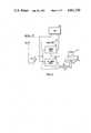
- FIG. 1is a block diagram of a preferred embodiment of an occupancy sensor system according to the present invention
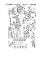
- FIG. 2is a schematic diagram of a preferred embodiment of the occupancy sensor of FIG. 1;
- FIG. 3is a schematic diagram of an alternative control circuit for the circuit of FIG. 2 for operation off of line power.
- FIG. 1shows an occupancy sensor 10 having a transmission plate 12 and a number of receivers 14.
- the occupancy sensor 10receives power through a pair of lines 16 which are coupled through a DC power supply 18 in a power pack 19 to line power neutral and hot lines 20 and 22, respectively.
- a control line 24 from occupancy sensor 10provides a signal to power relay 21 in power pack 19 which will couple hot line 22 to an electric load 26.
- the power relaycan be placed in series with a standard on/off switch 28.
- transmitter plate 12is vibrated at an ultrasonic frequency and the reflected signals are detected by receivers 14.
- a doppler shiftis detected on the reflected signals, this indicates the presence of human movement in the room.
- a control signal on line 24disables power relay 21, thereby removing power from load 26.
- the control signal on control line 24will enable power relay 21, thereby supplying power again to load 26.
- FIG. 2shows a preferred embodiment of a circuit implementing occupancy sensor 10 of FIG. 1.
- a transmitter circuit 30transmits an ultrasonic sound which is then reflected and detected by a receiver 32.
- the signal from receiver 32is passed through a highpass filter 34, bandpass filter 36 and lowpass demodulator 38 to produce the doppler-shift signal.
- the doppler-shift signalis then amplified in a variable gain amplifier 40 and supplied to a switching circuit 42.
- a narrowband filter 44selects the portions of the doppler shift signals which correspond to a frequency of human movement.
- the output of narrowband filter 44is supplied through a timeout circuit 46 to a comparator 48.
- Comparator 48provides an output signal to a control line 24 which goes to the power relay 18 of FIG. 1. Comparator 48 removes the signal from control line 24 a predetermined amount of time (determined by a timeout circuit 46) after no doppler-shift signal has been detected.
- a current limiter circuit 49is provided to limit the power drain on line 24.
- transmitter 30includes a crystal oscillator X1 which supplies a 25 kHz signal to a piezoelectric device P1.
- the signal supplied to each side of piezoelectric device P1is out of phase with the other signal, thus doubling the voltage applied.
- Piezoelectric device P1is coupled to a transmitter plate 12 as shown in FIG. 1.
- Plate 12is a circular aluminum plate with a diameter of 90 mm.
- the reflected ultrasonic signalsare received by receivers 32 and passed through a highpass filter 34.
- Bandpass filter 36selects the 25 kHz transmission frequency.
- Lowpass demodulator 38demodulates any doppler-shift signal which has modulated the 25 kHz signal and supplies the demodulated signal to variable gain amplifier 40.
- a potentiometer VR1 in amplifier 40provides a sensitivity adjustment which can be set at the factory.
- a second potentiometer VR2can be user adjusted to vary the sensitivity and thus adapt the occupancy sensor to different sized rooms.
- the output of potentiometer VR2goes to a second stage of the variable gain amplifier which includes a capacitor C12 and resistor R16 for further high frequency filtering and amplification of the signal.
- a switching circuit 42has a transistor Q3 which is switched on when no doppler signal is detected and is switched off when a doppler signal is detected.
- the output of switching circuit 42is provided to a narrow band filter 44 having a capacitor C17 which is charged up for the frequency of interest.
- the frequency of interestis selected as a narrow band of doppler-shift frequencies which correspond to the expected frequencies of human movement.
- the doppler shift frequencies corresponding to human movementare approximately 8 Hz to 56 Hz around the transmission frequency of 25 KHz ⁇ 0.1%.
- the amplifier of filter 44is a Schmitt trigger, thus providing precise definition of the narrow band. When a doppler shift frequency of the selected narrow band is detected, transistor Q4 will switch on, providing a connection to ground to discharge timeout circuit 46.
- comparator 48The output of comparator 48 is coupled through transistors Q5 and Q6 of current limiter circuit 49 to control line 24.
- transistor Q6When transistor Q6 is turned on, relay 18 of FIG. 1 will be enabled, thereby turning on the electric load.
- a bypass switch 50allows the bypassing of the occupancy sensor by coupling the base of transistor Q5 to +12 volts, thus insuring that the electric load will stay on at all times.
- a test switch 52is provided to couple a resistor R32 into timeout circuit 46. This resistor has a lower value than the combined value of resistor R31 and potentiometer VR3, thereby providing a much lower timeout period. Preferably, a short period of 15 seconds is provided while the normal timeout period can range from 3 to 10 minutes. Thus, the circuit can be tested without requiring the tester to wait an unduly long period of time.
- the circuit of FIG. 2is designed to operate on a 24 volt input supplied on a line 54 from power pack 19 of FIG. 1 to a regulator 56. Regulator 56 thus produces the 12 volts needed for the remaining circuitry.
- FIG. 3shows a power supply for the circuit of FIG. 2 which operates on AC line power. Power is provided across AC lines 58, 60 through an inductor L2 which passes the 60 Hertz signal to a regulator 62 which supplies the 12 volt power for the circuit of FIG. 2.
- a triac (or bidirectional SCR) Q7is normally in an off position, thus preventing power from line 58 circulating back through to line 60.
- the electric load controlled by the occupancy sensoris in series on line 60 and is thus not turned on unless triac Q7 is activated. Triac Q7 will be activated when a signal on line 64 activates triac Q8. Line 64 is coupled to the emitter of transistor Q6 of FIG. 2 in place of line 24.
- the present inventionmay be embodied in other specific forms without departing from the spirit or essential characteristics thereof.
- a number other than four receiverscould be used or the specific resistance and capacitive values shown in timeout circuit 46 could be varied. Accordingly, the disclosure of the preferred embodiment of the invention is intended to be illustrative, but not limiting, of the scope of the invention which is set forth in the following claims.
Landscapes
- Physics & Mathematics (AREA)
- Engineering & Computer Science (AREA)
- Radar, Positioning & Navigation (AREA)
- Remote Sensing (AREA)
- Acoustics & Sound (AREA)
- Computer Networks & Wireless Communication (AREA)
- General Physics & Mathematics (AREA)
- Geophysics And Detection Of Objects (AREA)
- Measurement Of Velocity Or Position Using Acoustic Or Ultrasonic Waves (AREA)
Abstract
Description
The present invention relates to occupancy sensors for controlling lights and other electric loads by detecting doppler shifts in transmitted ultrasonic sound.
An occupancy sensor will typically transmit ultrasonic sound waves via one or more transmitters which then reflect off of objects in the room and are detected by one or more receivers. A doppler shift of the reflected signals indicates the presence of movement within the room, and can be detected by noting frequency changes from the transmitted frequency. In the absence of a detected doppler shift, an electric load can be switched off, thereby conserving energy when no people are in the room. Some examples of such systems are shown in U.S. Pat. No. 3,781,859, U.S. Pat. No. 3,383,678, U.S. Pat. No. 3,721,972, U.S. Pat. No. 4,172,253 and U.S. Pat. No. 4,021,679.
The present invention is an improved apparatus for switching off power to an electric load in the absence of the detection of movement from the doppler shift of a transmission signal. An oscillator generates an ultrasonic transmission frequency which is transmitted via a transmission plate coupled to the oscillator. A plurality of receivers detect reflections of the ultrasonic sound signal and supply the detected signal to a bandpass filter which passes the transmission frequency. A low-pass demodulator will detect any doppler signal which modulates the transmission signal and will supply it to an amplifier for amplification. The amplified signal is then provided to a narrowband filter which will pass only a narrowband of doppler-shift signals which correspond to the frequencies of human movement. The signal is then supplied to a switching means which, when activated, will charge a first node. The first node is charged via a resistor and a capacitor coupled to a voltage source. A comparator is coupled to the first node and is also coupled to a voltage reference. The comparator will produce an output signal when the first node has a higher voltage than the voltage reference, thereby enabling a control means which will supply current to the electric load. The detected doppler signal discharges the timing capacitor voltage thus insuring that an output signal is supplied while movement is detected in the room to keep the electric load supplied with current.
A potentiometer is coupled to the amplifier to vary the gain thus enabling a single unit to be adaptable to different sized rooms, rather than requiring separate units for each size of a room. A test switch is provided to change the value of the resistor in the resistor/capacitor timing circuit to vary the amount of time an absence of movement is required before the electric load will be turned off. A large circular plate is used for transmission to provide wide coverage and constant transmission quality. Four receivers are at equally spaced positions around the plate to provide uniform reception and to allow the unit to be centrally placed within a room.
For a fuller understanding of the nature and advantages of the invention, reference should be made to the ensuing detailed description taken in conjunction with the accompanying drawings.
FIG. 1 is a block diagram of a preferred embodiment of an occupancy sensor system according to the present invention;
FIG. 2 is a schematic diagram of a preferred embodiment of the occupancy sensor of FIG. 1; and
FIG. 3 is a schematic diagram of an alternative control circuit for the circuit of FIG. 2 for operation off of line power.
FIG. 1 shows anoccupancy sensor 10 having atransmission plate 12 and a number ofreceivers 14. Theoccupancy sensor 10 receives power through a pair oflines 16 which are coupled through aDC power supply 18 in apower pack 19 to line power neutral andhot lines control line 24 fromoccupancy sensor 10 provides a signal to power relay 21 inpower pack 19 which will couplehot line 22 to anelectric load 26. The power relay can be placed in series with a standard on/offswitch 28.
In operation,transmitter plate 12 is vibrated at an ultrasonic frequency and the reflected signals are detected byreceivers 14. When a doppler shift is detected on the reflected signals, this indicates the presence of human movement in the room. When no doppler shift has been detected for a predetermined amount of time, a control signal online 24 disables power relay 21, thereby removing power fromload 26. When human movement is again detected, the control signal oncontrol line 24 will enable power relay 21, thereby supplying power again to load 26.
FIG. 2 shows a preferred embodiment of a circuit implementingoccupancy sensor 10 of FIG. 1. Generally, a transmitter circuit 30 transmits an ultrasonic sound which is then reflected and detected by areceiver 32. The signal fromreceiver 32 is passed through ahighpass filter 34,bandpass filter 36 andlowpass demodulator 38 to produce the doppler-shift signal. The doppler-shift signal is then amplified in avariable gain amplifier 40 and supplied to aswitching circuit 42. A narrowband filter 44 selects the portions of the doppler shift signals which correspond to a frequency of human movement. The output of narrowband filter 44 is supplied through atimeout circuit 46 to acomparator 48.Comparator 48 provides an output signal to acontrol line 24 which goes to thepower relay 18 of FIG. 1.Comparator 48 removes the signal from control line 24 a predetermined amount of time (determined by a timeout circuit 46) after no doppler-shift signal has been detected. Acurrent limiter circuit 49 is provided to limit the power drain online 24.
In more detail, transmitter 30 includes a crystal oscillator X1 which supplies a 25 kHz signal to a piezoelectric device P1. The signal supplied to each side of piezoelectric device P1 is out of phase with the other signal, thus doubling the voltage applied. Piezoelectric device P1 is coupled to atransmitter plate 12 as shown in FIG. 1.Plate 12 is a circular aluminum plate with a diameter of 90 mm.
The reflected ultrasonic signals are received byreceivers 32 and passed through ahighpass filter 34.Bandpass filter 36 selects the 25 kHz transmission frequency.Lowpass demodulator 38 demodulates any doppler-shift signal which has modulated the 25 kHz signal and supplies the demodulated signal tovariable gain amplifier 40.
A potentiometer VR1 inamplifier 40 provides a sensitivity adjustment which can be set at the factory. A second potentiometer VR2 can be user adjusted to vary the sensitivity and thus adapt the occupancy sensor to different sized rooms. The output of potentiometer VR2 goes to a second stage of the variable gain amplifier which includes a capacitor C12 and resistor R16 for further high frequency filtering and amplification of the signal.
Aswitching circuit 42 has a transistor Q3 which is switched on when no doppler signal is detected and is switched off when a doppler signal is detected. The output ofswitching circuit 42 is provided to a narrow band filter 44 having a capacitor C17 which is charged up for the frequency of interest. The frequency of interest is selected as a narrow band of doppler-shift frequencies which correspond to the expected frequencies of human movement. The doppler shift frequencies corresponding to human movement are approximately 8 Hz to 56 Hz around the transmission frequency of 25 KHz ± 0.1%. The amplifier of filter 44 is a Schmitt trigger, thus providing precise definition of the narrow band. When a doppler shift frequency of the selected narrow band is detected, transistor Q4 will switch on, providing a connection to ground to dischargetimeout circuit 46. In the absence of such a connection to ground, 12 volts supplied to resistor R31, potentiometer VR3 and capacitor C18 will charge a negative input ofcomparator 48 up to a high voltage in an amount of time determined by the setting of potentiometer VR3. When this voltage is charged up to a value greater than the value at the positive input ofcomparator 48, the electric load will be switched off. Thus, transistor Q4 prevents this charge from building up as long as human activity is detected within the room. A light-emitting diode D4 indicates that the circuit has detected movement.
The output ofcomparator 48 is coupled through transistors Q5 and Q6 ofcurrent limiter circuit 49 to controlline 24. When transistor Q6 is turned on,relay 18 of FIG. 1 will be enabled, thereby turning on the electric load. A bypass switch 50 allows the bypassing of the occupancy sensor by coupling the base of transistor Q5 to +12 volts, thus insuring that the electric load will stay on at all times. In addition, atest switch 52 is provided to couple a resistor R32 intotimeout circuit 46. This resistor has a lower value than the combined value of resistor R31 and potentiometer VR3, thereby providing a much lower timeout period. Preferably, a short period of 15 seconds is provided while the normal timeout period can range from 3 to 10 minutes. Thus, the circuit can be tested without requiring the tester to wait an unduly long period of time.
The circuit of FIG. 2 is designed to operate on a 24 volt input supplied on aline 54 frompower pack 19 of FIG. 1 to aregulator 56.Regulator 56 thus produces the 12 volts needed for the remaining circuitry.
FIG. 3 shows a power supply for the circuit of FIG. 2 which operates on AC line power. Power is provided acrossAC lines 58, 60 through an inductor L2 which passes the 60 Hertz signal to aregulator 62 which supplies the 12 volt power for the circuit of FIG. 2. A triac (or bidirectional SCR) Q7 is normally in an off position, thus preventing power from line 58 circulating back through toline 60. The electric load controlled by the occupancy sensor is in series online 60 and is thus not turned on unless triac Q7 is activated. Triac Q7 will be activated when a signal online 64 activates triac Q8.Line 64 is coupled to the emitter of transistor Q6 of FIG. 2 in place ofline 24.
As will be understood by those familiar with the art, the present invention may be embodied in other specific forms without departing from the spirit or essential characteristics thereof. For example, a number other than four receivers could be used or the specific resistance and capacitive values shown intimeout circuit 46 could be varied. Accordingly, the disclosure of the preferred embodiment of the invention is intended to be illustrative, but not limiting, of the scope of the invention which is set forth in the following claims.
Claims (8)
1. An apparatus for switching off power to an electric load in the absence of the detection of movement from the doppler shift of a transmission frequency, comprising:
oscillator means for generating an ultrasonic transmission frequency;
a transmission plate, coupled to said oscillator means, for emitting ultrasonic sound at said transmission frequency;
a plurality of receivers for detecting reflections of said ultrasonic sound;
a bandpass filter coupled to said receivers for passing said transmission frequency;
a lowpass demodulator coupled to said bandpass filter for passing a doppler-shift signal;
amplifier means, coupled to said lowpass demodulator, for amplifying said doppler-shift signal;
narrow band filter means, coupled to said amplifier means, for passing a band of said doppler-shift signal corresponding to human movement;
switching means, coupled to said narrow band filter means, for discharging a first node;
a resistor and capacitor coupled to said first node and to a voltage source for charging said first node to above a first voltage level in a first, predetermined time;
comparator means, having a first input coupled to said first node and a second input coupled to a voltage reference, for producing an output signal when said first input has a lower voltage than said second input; and
control means, coupled to said comparator means, for supplying current to said electric load in response to said output signal.
2. The apparatus of claim 1 wherein four of said receivers are used, each of said receivers being equally spaced around said transmission plate.
3. The apparatus of claim 1 wherein said transmission plate is circular and has a diameter greater than 75 mm.
4. The apparatus of claim 1 further comprising a test switch for coupling a second resistor to said first node and said voltage source to change the time constant of said resistor and capacitor.
5. The apparatus of claim 1 further comprising a potentiometer coupled in series with said resistor to enable a user to adjust the time constant of said resistor and capacitor.
6. The apparatus of claim 1 wherein said amplifier means includes a potentiometer which is user adjustable to vary the gain of said amplifier means.
7. The apparatus of claim 1 further comprising a power supply for supplying power to said apparatus.
8. An apparatus for switching off power to an electric load in the absence of the detection of movement from the doppler shift of a transmission frequency, comprising:
oscillator means for generating an ultrasonic transmission frequency;
a circular transmission plate, greater than 75 mm in diameter, coupled to said oscillator means, for emitting ultrasonic sound at said transmission frequency;
four receivers equally spaced around said transmission plate for detecting reflections of said ultrasonic sound;
a bandpass filter coupled to said receivers for passing said transmission frequency;
a lowpass demodulator coupled to said bandpass filter for passing a doppler-shift signal;
amplifier means, coupled to said lowpass demodulator, for amplifying said doppler-shift signal, said amplifier means including a user adjustable potentiometer for varying a gain of said amplifier means;
narrow band filter means, coupled to said amplifier means, for passing a band of said doppler-shift signal corresponding to human movement;
switching means, coupled to said narrow band filter means, for discharging a first node;
a potentiometer and a capacitor coupled in parallel to said first node and to a voltage source, for charging said first node to above a first voltage level in a first, predetermined time, said time being variable by user adjustment of said potentiometer;
a test switch for coupling a second resistor in parallel with said potentiometer and capacitor, said second resistance having a smaller value than said potentiometer;
comparator means, having a first input coupled to said first node and a second input coupled to a voltage reference, for producing an output signal when said first input has a lower voltage than said second input; and
control means, coupled to said comparator means, for supplying current to said electric load in response to said output signal.
Priority Applications (1)
| Application Number | Priority Date | Filing Date | Title |
|---|---|---|---|
| US06/872,308US4661720A (en) | 1986-06-09 | 1986-06-09 | Occupancy sensor |
Applications Claiming Priority (1)
| Application Number | Priority Date | Filing Date | Title |
|---|---|---|---|
| US06/872,308US4661720A (en) | 1986-06-09 | 1986-06-09 | Occupancy sensor |
Publications (1)
| Publication Number | Publication Date |
|---|---|
| US4661720Atrue US4661720A (en) | 1987-04-28 |
Family
ID=25359300
Family Applications (1)
| Application Number | Title | Priority Date | Filing Date |
|---|---|---|---|
| US06/872,308Expired - Fee RelatedUS4661720A (en) | 1986-06-09 | 1986-06-09 | Occupancy sensor |
Country Status (1)
| Country | Link |
|---|---|
| US (1) | US4661720A (en) |
Cited By (39)
| Publication number | Priority date | Publication date | Assignee | Title |
|---|---|---|---|---|
| US4751399A (en)* | 1986-12-11 | 1988-06-14 | Novitas, Inc. | Automatic lighting device |
| US4820938A (en)* | 1988-06-03 | 1989-04-11 | The Watt Watcher, Inc. | Low voltage motion sensor for activating a high voltage load |
| US4905165A (en)* | 1986-08-20 | 1990-02-27 | Chino Corporation | Measured data display device with strip chart simulation and table format |
| US4951045A (en)* | 1989-03-29 | 1990-08-21 | Intelligent Safety Technology, Inc. | Portable electronic warning device for temporary conditions |
| US5142199A (en)* | 1990-11-29 | 1992-08-25 | Novitas, Inc. | Energy efficient infrared light switch and method of making same |
| US5227762A (en)* | 1990-10-26 | 1993-07-13 | Thomas Industries Inc. | Power line carrier controlled lighting system |
| US5281961A (en)* | 1990-07-06 | 1994-01-25 | Novitas, Inc. | Motion detection sensor with computer interface |
| US5623172A (en)* | 1995-07-03 | 1997-04-22 | Leviton Manufacturing Co., Inc. | Two wire PIR occupancy sensor utilizing a rechargeable energy storage device |
| US5640143A (en)* | 1995-02-06 | 1997-06-17 | Mytech Corporation | Occupancy sensor and method of operating same |
| GR1002832B (en)* | 1996-10-23 | 1997-12-23 | . | Specialised ultrsonic radar functioning as an electronic switch operated by a suitable hand movement. |
| WO1998034206A1 (en)* | 1997-02-04 | 1998-08-06 | Mytech Corporation | Occupancy sensor and method of operating same |
| US5805767A (en)* | 1996-01-16 | 1998-09-08 | Jouas; Gary | Electronically-controlled heater |
| US5814902A (en)* | 1996-08-22 | 1998-09-29 | Light Minder | System and process for control of energy use by direct observation of occupancy |
| WO1999040453A3 (en)* | 1998-02-09 | 1999-11-04 | Stephen Barone | Motion detectors and occupancy sensors based on displacement detection |
| US5986357A (en)* | 1997-02-04 | 1999-11-16 | Mytech Corporation | Occupancy sensor and method of operating same |
| USRE37135E1 (en) | 1990-11-29 | 2001-04-17 | Novitas, Inc. | Fully automatic energy efficient lighting control and method of making same |
| USD472525S1 (en) | 2001-07-18 | 2003-04-01 | Stephen Barone | Decorative rocker switch |
| US6690018B1 (en) | 1998-10-30 | 2004-02-10 | Electro-Optic Technologies, Llc | Motion detectors and occupancy sensors with improved sensitivity, angular resolution and range |
| US6756595B2 (en) | 2000-09-11 | 2004-06-29 | Electro-Optic Technologies, Llc | Effective quad-detector occupancy sensors and motion detectors |
| US6759954B1 (en) | 1997-10-15 | 2004-07-06 | Hubbell Incorporated | Multi-dimensional vector-based occupancy sensor and method of operating same |
| USD499703S1 (en) | 2003-06-18 | 2004-12-14 | Electro-Optic Technologies, Llc | Decorative rocker switch |
| USD503387S1 (en) | 2001-07-18 | 2005-03-29 | Electro-Optic Technologies, Llc | Decorative rocker switch |
| USD505119S1 (en) | 1999-10-27 | 2005-05-17 | Electro-Optic Technologies, Llc | Decorative rocker switch |
| US20070273539A1 (en)* | 2006-05-26 | 2007-11-29 | Cooper Technologies Company | System for controlling a lamp as a function of at least one of occupancy and ambient light |
| US20070273509A1 (en)* | 2006-05-26 | 2007-11-29 | Cooper Technologies Company | System for controlling the operation of a lamp in multiple operational modes |
| US20080122295A1 (en)* | 2006-11-28 | 2008-05-29 | Daming Yu | Motion sensor switch for 3-way light circuit and method of lighting control using the same |
| CN100423434C (en)* | 2005-12-01 | 2008-10-01 | 居小平 | Ultrasonic Doppler switch power supply input controller |
| US20100237711A1 (en)* | 2009-03-18 | 2010-09-23 | Leviton Manufacturing Co., Inc. | Occupancy Sensing With Device Clock |
| US20100277306A1 (en)* | 2009-05-01 | 2010-11-04 | Leviton Manufacturing Co., Inc. | Wireless occupancy sensing with accessible location power switching |
| US20110012433A1 (en)* | 2009-07-15 | 2011-01-20 | Leviton Manufacturing Co., Inc. | Wireless occupancy sensing with portable power switching |
| US7924174B1 (en) | 2006-05-26 | 2011-04-12 | Cooper Technologies Company | System for controlling a lighting level of a lamp in a multi-zone environment |
| US7924155B2 (en) | 2008-01-07 | 2011-04-12 | Leviton Manufacturing Co., Inc. | Digital occupancy sensor light control |
| US20110148193A1 (en)* | 2009-12-23 | 2011-06-23 | Schneider Electric USA, Inc. | Networked occupancy sensor and power pack |
| US20110148309A1 (en)* | 2009-12-23 | 2011-06-23 | Schneider Electric USA, Inc. | Occupancy sensor with embedded signaling capability |
| US20110156911A1 (en)* | 2009-12-30 | 2011-06-30 | Leviton Manufacturing Co., Inc. | Occupancy-based control system |
| US8436541B2 (en) | 2010-12-30 | 2013-05-07 | Schneider Electric USA, Inc. | Occupancy sensor with multi-level signaling |
| US8981299B2 (en) | 2008-01-07 | 2015-03-17 | Leviton Manufacturing Company, Inc. | Digital occupancy sensor light control |
| CN105513243A (en)* | 2015-11-27 | 2016-04-20 | 国家电网公司 | External damage prevention device for power transmission line |
| USRE49828E1 (en)* | 2013-12-19 | 2024-02-06 | Lutron Technology Company Llc | Ultrasonic sensing system |
Citations (11)
| Publication number | Priority date | Publication date | Assignee | Title |
|---|---|---|---|---|
| US3634884A (en)* | 1970-03-02 | 1972-01-11 | Larson Ind Inc | Motion detection system |
| US3781859A (en)* | 1972-04-19 | 1973-12-25 | Seabroad Electric | Controlled wave pattern ultrasonic burglar alarm |
| US4097853A (en)* | 1976-09-20 | 1978-06-27 | Milwaukee Resistor Corporation | Means for distinguishing motion from noise in an intrusion alarm system |
| US4099168A (en)* | 1975-11-06 | 1978-07-04 | Magnum Products, Inc. | Intrusion alarm and emergency illumination apparatus and method |
| US4207559A (en)* | 1977-09-26 | 1980-06-10 | Meyer Michael M | Alarm system with acoustically coupled transmitters and receiver |
| US4307387A (en)* | 1979-02-23 | 1981-12-22 | Elliott Brothers (London) Limited | Vibration-responsive intruder alarm system |
| US4315596A (en)* | 1980-03-11 | 1982-02-16 | Innkeepers Electronics, Inc. | Energy conservation system for inns, hotels, and motels |
| US4319349A (en)* | 1978-09-29 | 1982-03-09 | Pittway Corporation | Ultrasonic intrusion detection system |
| US4321586A (en)* | 1980-08-21 | 1982-03-23 | Knogo Corporation | Article theft detection |
| US4361767A (en)* | 1980-03-24 | 1982-11-30 | National Technical Systems | Apparatus and method for controlling electrical equipment |
| US4391406A (en)* | 1982-01-07 | 1983-07-05 | Morton Fried | Power saving system which assures room security |
- 1986
- 1986-06-09USUS06/872,308patent/US4661720A/ennot_activeExpired - Fee Related
Patent Citations (11)
| Publication number | Priority date | Publication date | Assignee | Title |
|---|---|---|---|---|
| US3634884A (en)* | 1970-03-02 | 1972-01-11 | Larson Ind Inc | Motion detection system |
| US3781859A (en)* | 1972-04-19 | 1973-12-25 | Seabroad Electric | Controlled wave pattern ultrasonic burglar alarm |
| US4099168A (en)* | 1975-11-06 | 1978-07-04 | Magnum Products, Inc. | Intrusion alarm and emergency illumination apparatus and method |
| US4097853A (en)* | 1976-09-20 | 1978-06-27 | Milwaukee Resistor Corporation | Means for distinguishing motion from noise in an intrusion alarm system |
| US4207559A (en)* | 1977-09-26 | 1980-06-10 | Meyer Michael M | Alarm system with acoustically coupled transmitters and receiver |
| US4319349A (en)* | 1978-09-29 | 1982-03-09 | Pittway Corporation | Ultrasonic intrusion detection system |
| US4307387A (en)* | 1979-02-23 | 1981-12-22 | Elliott Brothers (London) Limited | Vibration-responsive intruder alarm system |
| US4315596A (en)* | 1980-03-11 | 1982-02-16 | Innkeepers Electronics, Inc. | Energy conservation system for inns, hotels, and motels |
| US4361767A (en)* | 1980-03-24 | 1982-11-30 | National Technical Systems | Apparatus and method for controlling electrical equipment |
| US4321586A (en)* | 1980-08-21 | 1982-03-23 | Knogo Corporation | Article theft detection |
| US4391406A (en)* | 1982-01-07 | 1983-07-05 | Morton Fried | Power saving system which assures room security |
Cited By (49)
| Publication number | Priority date | Publication date | Assignee | Title |
|---|---|---|---|---|
| US4905165A (en)* | 1986-08-20 | 1990-02-27 | Chino Corporation | Measured data display device with strip chart simulation and table format |
| US4751399A (en)* | 1986-12-11 | 1988-06-14 | Novitas, Inc. | Automatic lighting device |
| US4820938A (en)* | 1988-06-03 | 1989-04-11 | The Watt Watcher, Inc. | Low voltage motion sensor for activating a high voltage load |
| US4951045A (en)* | 1989-03-29 | 1990-08-21 | Intelligent Safety Technology, Inc. | Portable electronic warning device for temporary conditions |
| US5281961A (en)* | 1990-07-06 | 1994-01-25 | Novitas, Inc. | Motion detection sensor with computer interface |
| US5227762A (en)* | 1990-10-26 | 1993-07-13 | Thomas Industries Inc. | Power line carrier controlled lighting system |
| US5475360A (en)* | 1990-10-26 | 1995-12-12 | Thomas Industries, Inc. | Power line carrier controlled lighting system |
| US5142199A (en)* | 1990-11-29 | 1992-08-25 | Novitas, Inc. | Energy efficient infrared light switch and method of making same |
| USRE37135E1 (en) | 1990-11-29 | 2001-04-17 | Novitas, Inc. | Fully automatic energy efficient lighting control and method of making same |
| US5640143A (en)* | 1995-02-06 | 1997-06-17 | Mytech Corporation | Occupancy sensor and method of operating same |
| US5623172A (en)* | 1995-07-03 | 1997-04-22 | Leviton Manufacturing Co., Inc. | Two wire PIR occupancy sensor utilizing a rechargeable energy storage device |
| US5786644A (en)* | 1995-07-03 | 1998-07-28 | Leviton Manufacturing Co., Inc. | Two wire PIR occupancy sensor utilizing a rechargeable energy storage device |
| US5805767A (en)* | 1996-01-16 | 1998-09-08 | Jouas; Gary | Electronically-controlled heater |
| US5814902A (en)* | 1996-08-22 | 1998-09-29 | Light Minder | System and process for control of energy use by direct observation of occupancy |
| GR1002832B (en)* | 1996-10-23 | 1997-12-23 | . | Specialised ultrsonic radar functioning as an electronic switch operated by a suitable hand movement. |
| US6415205B1 (en) | 1997-02-04 | 2002-07-02 | Mytech Corporation | Occupancy sensor and method of operating same |
| US5986357A (en)* | 1997-02-04 | 1999-11-16 | Mytech Corporation | Occupancy sensor and method of operating same |
| US6078253A (en)* | 1997-02-04 | 2000-06-20 | Mytech Corporation | Occupancy sensor and method of operating same |
| WO1998034206A1 (en)* | 1997-02-04 | 1998-08-06 | Mytech Corporation | Occupancy sensor and method of operating same |
| US6759954B1 (en) | 1997-10-15 | 2004-07-06 | Hubbell Incorporated | Multi-dimensional vector-based occupancy sensor and method of operating same |
| WO1999040453A3 (en)* | 1998-02-09 | 1999-11-04 | Stephen Barone | Motion detectors and occupancy sensors based on displacement detection |
| US6690018B1 (en) | 1998-10-30 | 2004-02-10 | Electro-Optic Technologies, Llc | Motion detectors and occupancy sensors with improved sensitivity, angular resolution and range |
| US20050045826A1 (en)* | 1998-10-30 | 2005-03-03 | Stephen Barone | Motion detectors and occupancy sensors with improved sensitivity, angular resolution and range |
| US7053374B2 (en) | 1998-10-30 | 2006-05-30 | Electro-Optic Technologies, Llc | Motion detectors and occupancy sensors with improved sensitivity, angular resolution and range |
| USD505119S1 (en) | 1999-10-27 | 2005-05-17 | Electro-Optic Technologies, Llc | Decorative rocker switch |
| US6756595B2 (en) | 2000-09-11 | 2004-06-29 | Electro-Optic Technologies, Llc | Effective quad-detector occupancy sensors and motion detectors |
| US6921900B2 (en) | 2000-09-11 | 2005-07-26 | Electro-Optic Technologies, Llc | Effective quad-detector occupancy sensors and motion detectors |
| USD472525S1 (en) | 2001-07-18 | 2003-04-01 | Stephen Barone | Decorative rocker switch |
| USD503387S1 (en) | 2001-07-18 | 2005-03-29 | Electro-Optic Technologies, Llc | Decorative rocker switch |
| USD499703S1 (en) | 2003-06-18 | 2004-12-14 | Electro-Optic Technologies, Llc | Decorative rocker switch |
| USD502930S1 (en) | 2003-06-18 | 2005-03-15 | Electro-Optic Technologies, Llc | Decorative rocker switch |
| CN100423434C (en)* | 2005-12-01 | 2008-10-01 | 居小平 | Ultrasonic Doppler switch power supply input controller |
| US20070273539A1 (en)* | 2006-05-26 | 2007-11-29 | Cooper Technologies Company | System for controlling a lamp as a function of at least one of occupancy and ambient light |
| US20070273509A1 (en)* | 2006-05-26 | 2007-11-29 | Cooper Technologies Company | System for controlling the operation of a lamp in multiple operational modes |
| US7924174B1 (en) | 2006-05-26 | 2011-04-12 | Cooper Technologies Company | System for controlling a lighting level of a lamp in a multi-zone environment |
| US20080122295A1 (en)* | 2006-11-28 | 2008-05-29 | Daming Yu | Motion sensor switch for 3-way light circuit and method of lighting control using the same |
| US7791282B2 (en) | 2006-11-28 | 2010-09-07 | Hubbell Incorporated | Motion sensor switch for 3-way light circuit and method of lighting control using the same |
| US8981299B2 (en) | 2008-01-07 | 2015-03-17 | Leviton Manufacturing Company, Inc. | Digital occupancy sensor light control |
| US7924155B2 (en) | 2008-01-07 | 2011-04-12 | Leviton Manufacturing Co., Inc. | Digital occupancy sensor light control |
| US20100237711A1 (en)* | 2009-03-18 | 2010-09-23 | Leviton Manufacturing Co., Inc. | Occupancy Sensing With Device Clock |
| US20100277306A1 (en)* | 2009-05-01 | 2010-11-04 | Leviton Manufacturing Co., Inc. | Wireless occupancy sensing with accessible location power switching |
| US20110012433A1 (en)* | 2009-07-15 | 2011-01-20 | Leviton Manufacturing Co., Inc. | Wireless occupancy sensing with portable power switching |
| US8258654B2 (en)* | 2009-07-15 | 2012-09-04 | Leviton Manufacturing Co., Inc. | Wireless occupancy sensing with portable power switching |
| US20110148309A1 (en)* | 2009-12-23 | 2011-06-23 | Schneider Electric USA, Inc. | Occupancy sensor with embedded signaling capability |
| US20110148193A1 (en)* | 2009-12-23 | 2011-06-23 | Schneider Electric USA, Inc. | Networked occupancy sensor and power pack |
| US20110156911A1 (en)* | 2009-12-30 | 2011-06-30 | Leviton Manufacturing Co., Inc. | Occupancy-based control system |
| US8436541B2 (en) | 2010-12-30 | 2013-05-07 | Schneider Electric USA, Inc. | Occupancy sensor with multi-level signaling |
| USRE49828E1 (en)* | 2013-12-19 | 2024-02-06 | Lutron Technology Company Llc | Ultrasonic sensing system |
| CN105513243A (en)* | 2015-11-27 | 2016-04-20 | 国家电网公司 | External damage prevention device for power transmission line |
Similar Documents
| Publication | Publication Date | Title |
|---|---|---|
| US4661720A (en) | Occupancy sensor | |
| US4820938A (en) | Low voltage motion sensor for activating a high voltage load | |
| US5640143A (en) | Occupancy sensor and method of operating same | |
| US4101873A (en) | Device to locate commonly misplaced objects | |
| US5945918A (en) | Apparatus and method for locating a remote control unit | |
| US5790035A (en) | Reusable temperature and wetness alarm device for the diaper | |
| US5708421A (en) | System for tracking an article or person | |
| US5189393A (en) | Dual technology motion sensor | |
| US5287111A (en) | Doppler shift motion detector with variable power | |
| US4344071A (en) | Light switching mechanism | |
| US7019649B2 (en) | Pool monitoring | |
| CA2159976A1 (en) | Method and apparatus for leveling audio output | |
| GB2315123A (en) | Solar lamp | |
| US4032909A (en) | Arrangement for testing an alarm system and method | |
| WO1993005627A1 (en) | Method and apparatus for detecting entry | |
| US4361767A (en) | Apparatus and method for controlling electrical equipment | |
| US3559194A (en) | Fire alarm system | |
| US3569924A (en) | Ultrasonic detection system | |
| US3629812A (en) | Turbulence-compensated ultrasonic intruder detector | |
| US4975964A (en) | Automatic turn off system | |
| US3793617A (en) | Ultrasonic area surveillance system | |
| US4414534A (en) | Radio frequency detection circuitry having noise discrimination capability | |
| US3818479A (en) | Direction finder | |
| JP2892389B2 (en) | Fire detector with test equipment | |
| KR880002869Y1 (en) | Tone burst wave contoller |
Legal Events
| Date | Code | Title | Description |
|---|---|---|---|
| AS | Assignment | Owner name:WATT WATCHER, INC., THE, P. O. BOX 2058 SANTA CLAR Free format text:ASSIGNMENT OF ASSIGNORS INTEREST.;ASSIGNORS:CAMERON, MACLYN C. JR.;HU, CHARLES C.;MIX, JEROME M.;REEL/FRAME:004580/0091 Effective date:19860606 | |
| FEPP | Fee payment procedure | Free format text:PAYOR NUMBER ASSIGNED (ORIGINAL EVENT CODE: ASPN); ENTITY STATUS OF PATENT OWNER: SMALL ENTITY | |
| FPAY | Fee payment | Year of fee payment:4 | |
| AS | Assignment | Owner name:WATT STOPPER INCORPORATED, THE Free format text:CHANGE OF NAME;ASSIGNOR:WALT WATCHER INC., THE;REEL/FRAME:006032/0196 Effective date:19920218 | |
| FPAY | Fee payment | Year of fee payment:8 | |
| REMI | Maintenance fee reminder mailed | ||
| LAPS | Lapse for failure to pay maintenance fees | ||
| FP | Lapsed due to failure to pay maintenance fee | Effective date:19990428 | |
| STCH | Information on status: patent discontinuation | Free format text:PATENT EXPIRED DUE TO NONPAYMENT OF MAINTENANCE FEES UNDER 37 CFR 1.362 |