US4660050A - Doppler radar velocity measurement horn - Google Patents
Doppler radar velocity measurement hornDownload PDFInfo
- Publication number
- US4660050A US4660050AUS06/482,527US48252783AUS4660050AUS 4660050 AUS4660050 AUS 4660050AUS 48252783 AUS48252783 AUS 48252783AUS 4660050 AUS4660050 AUS 4660050A
- Authority
- US
- United States
- Prior art keywords
- horn
- assembly
- wave
- lens
- set forth
- Prior art date
- Legal status (The legal status is an assumption and is not a legal conclusion. Google has not performed a legal analysis and makes no representation as to the accuracy of the status listed.)
- Expired - Fee Related
Links
- 238000005259measurementMethods0.000titleclaimsdescription10
- 229910052782aluminiumInorganic materials0.000claimsabstractdescription16
- XAGFODPZIPBFFR-UHFFFAOYSA-NaluminiumChemical compound[Al]XAGFODPZIPBFFR-UHFFFAOYSA-N0.000claimsabstractdescription16
- 230000009977dual effectEffects0.000claimsabstractdescription14
- 229910000831SteelInorganic materials0.000claimsabstractdescription12
- 239000010959steelSubstances0.000claimsabstractdescription12
- 239000011213glass-filled polymerSubstances0.000claimsabstractdescription11
- 230000000712assemblyEffects0.000claimsabstractdescription10
- 238000000429assemblyMethods0.000claimsabstractdescription10
- 230000008602contractionEffects0.000claimsabstractdescription9
- 239000000463materialSubstances0.000claimsdescription39
- 239000012858resilient materialSubstances0.000claimsdescription14
- 239000011521glassSubstances0.000claimsdescription7
- 125000006850spacer groupChemical group0.000claimsdescription7
- 238000013016dampingMethods0.000claimsdescription5
- 229920000728polyesterPolymers0.000claimsdescription5
- 230000035939shockEffects0.000claimsdescription4
- 230000007704transitionEffects0.000claimsdescription3
- 230000000295complement effectEffects0.000claimsdescription2
- 238000001914filtrationMethods0.000claims3
- 230000005855radiationEffects0.000description9
- 239000002131composite materialSubstances0.000description4
- 230000010287polarizationEffects0.000description4
- 239000006185dispersionSubstances0.000description3
- 230000004044responseEffects0.000description3
- 239000004698PolyethyleneSubstances0.000description2
- 239000011324beadSubstances0.000description2
- 230000008901benefitEffects0.000description2
- 239000003989dielectric materialSubstances0.000description2
- 230000000694effectsEffects0.000description2
- 238000002955isolationMethods0.000description2
- 239000007788liquidSubstances0.000description2
- 229910052751metalInorganic materials0.000description2
- 239000002184metalSubstances0.000description2
- 238000000034methodMethods0.000description2
- 229920000573polyethylenePolymers0.000description2
- -1polyethylenesPolymers0.000description2
- 229920000642polymerPolymers0.000description2
- 229920002379silicone rubberPolymers0.000description2
- 239000007787solidSubstances0.000description2
- 238000012935AveragingMethods0.000description1
- 229910001369BrassInorganic materials0.000description1
- XUIMIQQOPSSXEZ-UHFFFAOYSA-NSiliconChemical compound[Si]XUIMIQQOPSSXEZ-UHFFFAOYSA-N0.000description1
- 230000001133accelerationEffects0.000description1
- 230000001154acute effectEffects0.000description1
- 230000002411adverseEffects0.000description1
- 230000004075alterationEffects0.000description1
- 239000004411aluminiumSubstances0.000description1
- 230000003466anti-cipated effectEffects0.000description1
- 238000013459approachMethods0.000description1
- 239000010951brassSubstances0.000description1
- 230000006835compressionEffects0.000description1
- 238000007906compressionMethods0.000description1
- 238000007796conventional methodMethods0.000description1
- 230000005574cross-species transmissionEffects0.000description1
- 230000000593degrading effectEffects0.000description1
- 230000001419dependent effectEffects0.000description1
- 238000006073displacement reactionMethods0.000description1
- 230000007613environmental effectEffects0.000description1
- 230000005284excitationEffects0.000description1
- 239000003337fertilizerSubstances0.000description1
- 239000004009herbicideSubstances0.000description1
- 238000005286illuminationMethods0.000description1
- 238000002347injectionMethods0.000description1
- 239000007924injectionSubstances0.000description1
- 238000001746injection mouldingMethods0.000description1
- 238000003780insertionMethods0.000description1
- 230000037431insertionEffects0.000description1
- 150000002739metalsChemical class0.000description1
- 239000002245particleSubstances0.000description1
- 239000000575pesticideSubstances0.000description1
- 230000008569processEffects0.000description1
- 238000012545processingMethods0.000description1
- 230000008707rearrangementEffects0.000description1
- 229910052710siliconInorganic materials0.000description1
- 239000010703siliconSubstances0.000description1
- 239000000243solutionSubstances0.000description1
- 239000000725suspensionSubstances0.000description1
- 238000012360testing methodMethods0.000description1
Images
Classifications
- F—MECHANICAL ENGINEERING; LIGHTING; HEATING; WEAPONS; BLASTING
- F16—ENGINEERING ELEMENTS AND UNITS; GENERAL MEASURES FOR PRODUCING AND MAINTAINING EFFECTIVE FUNCTIONING OF MACHINES OR INSTALLATIONS; THERMAL INSULATION IN GENERAL
- F16F—SPRINGS; SHOCK-ABSORBERS; MEANS FOR DAMPING VIBRATION
- F16F15/00—Suppression of vibrations in systems; Means or arrangements for avoiding or reducing out-of-balance forces, e.g. due to motion
- F16F15/02—Suppression of vibrations of non-rotating, e.g. reciprocating systems; Suppression of vibrations of rotating systems by use of members not moving with the rotating systems
- F16F15/04—Suppression of vibrations of non-rotating, e.g. reciprocating systems; Suppression of vibrations of rotating systems by use of members not moving with the rotating systems using elastic means
- F16F15/08—Suppression of vibrations of non-rotating, e.g. reciprocating systems; Suppression of vibrations of rotating systems by use of members not moving with the rotating systems using elastic means with rubber springs ; with springs made of rubber and metal
- G—PHYSICS
- G01—MEASURING; TESTING
- G01S—RADIO DIRECTION-FINDING; RADIO NAVIGATION; DETERMINING DISTANCE OR VELOCITY BY USE OF RADIO WAVES; LOCATING OR PRESENCE-DETECTING BY USE OF THE REFLECTION OR RERADIATION OF RADIO WAVES; ANALOGOUS ARRANGEMENTS USING OTHER WAVES
- G01S13/00—Systems using the reflection or reradiation of radio waves, e.g. radar systems; Analogous systems using reflection or reradiation of waves whose nature or wavelength is irrelevant or unspecified
- G01S13/02—Systems using reflection of radio waves, e.g. primary radar systems; Analogous systems
- G01S13/50—Systems of measurement based on relative movement of target
- G01S13/58—Velocity or trajectory determination systems; Sense-of-movement determination systems
- G01S13/60—Velocity or trajectory determination systems; Sense-of-movement determination systems wherein the transmitter and receiver are mounted on the moving object, e.g. for determining ground speed, drift angle, ground track
- H—ELECTRICITY
- H01—ELECTRIC ELEMENTS
- H01Q—ANTENNAS, i.e. RADIO AERIALS
- H01Q19/00—Combinations of primary active antenna elements and units with secondary devices, e.g. with quasi-optical devices, for giving the antenna a desired directional characteristic
- H01Q19/06—Combinations of primary active antenna elements and units with secondary devices, e.g. with quasi-optical devices, for giving the antenna a desired directional characteristic using refracting or diffracting devices, e.g. lens
- H01Q19/08—Combinations of primary active antenna elements and units with secondary devices, e.g. with quasi-optical devices, for giving the antenna a desired directional characteristic using refracting or diffracting devices, e.g. lens for modifying the radiation pattern of a radiating horn in which it is located
Definitions
- the present inventionrelates to doppler radar apparatus for use in measuring the velocity of vehicles such as a farm tractors and the like.
- the speed of farm tractors and other off-highway equipmentis not easily determined with accuracy.
- the conventional method of measuring the speed of a vehiclei.e., by measuring the rate of revolution of the wheels which drive the vehicle, is not accurate when applied to farm tractors, for example, due to the high rate of slip of the driven wheels relative to the ground.
- Measuring the speed of a tractor by measuring the rate of rotation of the tractor's undriven wheelsis also inaccurate because the wheels tend to skid during turning and to lift off the ground under certain circumstances.
- Doppler radaroperates by broadcasting a radio frequency (RF) electromagnetic wave in a thin beam, and measuring the frequency of the wave reflected from the ground relative to the frequency of the broadcast wave. The difference between the two frequencies is directly proportional to the speed of the vehicle.
- RFradio frequency
- the doppler radar apparatusshould ideally produce a narrow radar beam with substantially no side lobes, so that the beam can be pointed at a defined area of the ground and will not strike and be reflected from adjacent structures, such as vehicle tires.
- the radiation pattern of the electromagnetic wave generated by the doppler radar apparatusis dependent upon the characteristics of the antenna used with the apparatus.
- One type of antenna known to have low levels of side lobesis the so-called “dual mode" horn antenna. Dual mode horn antennas are described in the P. D. Potter article entitled “A New Horn Antenna With Suppressed Side Lobe and Equal Beam Widths", the microwave journal, pages 71-78 (June, 1963).
- Dual mode horn antennasare designed so that the electromagnetic wave propagates through the horn in two modes.
- the radiation pattern of the antennais a composite of the patterns produced by the two modes, and includes substantially no side lobes since the side lobes produced by one mode cancel the side lobes produced by the other mode.
- the composite pattern thus producedhas essentially no radiation energy outside of the main or axial lobe.
- the hornhad to be designed to have a rather small flare angle, on the order of 12.5°. A small flare angle results in a relatively long horn, however, since the length of a horn is established by its flare angle.
- the diameter of the horn mouthis essentially determined in accordance with the desired gain and beam width of the resulting RF pattern. Given the preferred horn diameter of four to five inches for land vehicle applications using frequencies in the 24 GHz range, a horn must be nearly two feet long in order to have a 12.5° flare angle. A two foot long horn is simply too large to be of practical use on farm tractors and other off-road vehicles.
- the hornmust be capable of withstanding the severe mechanical shocks to which a farm tractor or other off-road vehicle will be subjected.
- Some materials normally used in electromagnetic antennas or their componentsare not entirely suitable for use in off-road vehicles.
- the dielectric lenses sometimes used on horn antennas, for example,are generally constructed of pure polymeric materials. Such materials are brittle and somewhat weak, and would therefore be subject to breakage if used on a farm tractor or other off-road vehicle.
- Other dielectricscan be substituted for the polyethylenes normally used in RF lens structures. Any dielectric material that is used, however, must generally conform to certain standards of homogeniety, since inhomogeneousness of the material may result in dispersion or polarization of the RF wave which is being focused by the lens.
- the horn and its related microwave componentsare generally formed of aluminum, since aluminum is easily cast into the complex shapes in which the components are to be formed.
- the exterior housing and horn mounting componentsshould preferably be formed of steel since steel is inexpensive and rugged.
- Another problem of the typical doppler radar systemrelates to the observed tendency of doppler radar systems to indicate that a vehicle is moving when it is in fact stopped.
- One method of avoiding such erroneous indicationswould be to disable the speed indication provided by the doppler radar whenever the vehicle tires remained stationary for more than a selected time period.
- Such a solution to the problemcomplicates the electrical interconnection between the doppler radar system with the rest of the vehicle, however, and is undesirable for that reason.
- the problemis solved by disabling the speed indication whenever it is below a selected threshold speed. It would be desirable if a doppler radar system could be devised which simply did not provide the erroneous velocity indication in the first place.
- the present inventionrelates to doppler radar velocity measurement apparatus that has electrical and mechanical characteristics which render it suitable for use on off-road vehicles such as farm tractors and the like.
- the apparatus of the inventionis a small, compact package that generates a narrow, well-defined beam of microwave energy having substantially no side lobes.
- the apparatusprovides substantially zero output when the vehicle is halted, and is both durable and temperature resistant.
- the doppler radar apparatus in accordance with the present inventionuses a dual mode horn antenna having a flare angle which is substantially in excess of the 12.5° normally used.
- the horn used in the described embodimenthas a flare angle of 38.84°.
- the horndoes not suffer from the mode phasing problems which had been anticipated.
- the length of the horn necessary to arrive at the desired horn mouth diameteris substantially reduced.
- the dual mode hornis short enough for use on off-road vehicles.
- the hornemploys a dielectric lens positioned over the horn so as to assist in focusing of the beam.
- the lensis formed of a glass filled polymer. Surprisingly, the glass filling does not interfere with the electrical characteristics of the lens.
- the glass filled polymerprovides a lens of substantially greater strength than conventional lenses formed, for example, of pure polyester material.
- the doppler radar apparatus of the inventionis designed such that the fit between the microwave horn assembly and the housing assembly does not loosen with temperature variations, even though the two assemblies are constructed of different materials.
- the housing assemblyhas interior surfaces which abut matching exterior surfaces of the microwave horn assembly.
- the planes of the abutting surfacesare selected to be parallel to the direction of expansion or contraction of the assemblies due to temperature variations.
- Unequal expansion or contraction of the different structural materials of which the housing and horn assemblies are fabricatedthus cause sliding of the abutting surfaces relative to one another rather than loosening of the fit between the assemblies.
- the apparatus of the inventionincludes vibration isolators whose spring rate and damping characteristics are selected in accordance with the characteristics of a high-pass filter used to filter the doppler signal provided by the apparatus. More particularly, the spring rate and damping characteristics of the vibration isolator are selected such that low level vibrations of frequencies which would produce doppler frequencies greater than the cut-off frequency of the high-pass filter are not transmitted to the microwave horn assembly.
- FIG. 1is a side elevation view of a farm tractor, indicating the location at which doppler radar apparatus could be mounted;
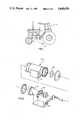
- FIG. 2is an exploded view of doppler radar apparatus in accordance with the teachings of the present invention.
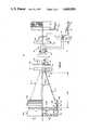
- FIG. 3is an exploded quarter section side view of the microwave horn assembly of the FIG. 2 apparatus
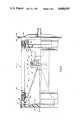
- FIG. 4is a quarter section side view of the assembled unit
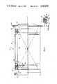
- FIG. 5is a quarter section side view of the housing assembly of the FIG. 2 apparatus.
- FIG. 5Ais an enlarged sectional view of the vibration isolators of the housing assembly.
- a doppler radar unitis largely self-contained and must be mounted on a vehicle such that the beam of microwave energy which it generates will strike and be reflected from the ground beneath the vehicle.
- the doppler radar unitcan be mounted either at the front or back of some vehicles, since in both places there is generally an unrestricted view of the ground over which the vehicle is passing.
- front and rear mounted implementssuch as stackers and plows may interfere with the operation of the doppler radar.
- the doppler radar unitmust be mounted on the side of a tractor.
- the doppler radar unitshould preferably be mounted near the center of the tractor, and can be pointed either forward or rearward.
- FIG. 1shows a farm tractor 10 with a doppler radar unit 12 mounted at a representative location on the side of the vehicle.
- the beam 14 generated by the unitilluminates the ground between the rear tires. It is therefore important that the beam be confined in width. If the beam has excessive spillover in the area of the wheels, microwave energy will be reflected from the wheels which will substantially interfere with the operation of the unit. To prevent this from occurring, the unit must produce a beam having a narrow width and virtually no side lobes. If the area illuminated by the radar unit is too small, however, irregularities in the ground surface will produce marked deviations in the velocity measured by the system. By broadening out the beam to cover, for example, 5°-8°, sufficient ground area is illuminated that a spatial averaging effect takes place, whereby the mean frequency of the returned microwave signal is accurately representative of the actual speed of the vehicle.
- a doppler radar velocity measurement system in accordance with the teachings of the present inventionis illustrated in partially disassembled form in FIG. 2.
- the systemincludes two major assemblies--a microwave horn assembly 22 and a housing assembly 24.
- a printed circuit board 26is connected to the microwave horn assembly 22 by an electrical cable 28.
- FIG. 3A quarter sectional, side view of most of the major parts of the microwave horn assembly 22 is shown in FIG. 3.
- the microwave horn assembly 22includes a microwave transceiver 32, a waveguide transformer 34, a mode generator and horn antenna 36, and a horn cover 38 which incorporates a dielectric lens.
- Certain related electronic circuits 39, 40, and 41,are contained on the printed circuit board 26 (FIG. 2) which is mounted on the microwave horn assembly.
- the microwave transceiver 32is a conventional component and therefore will not be described in detail.
- the transceiver 32is not sectioned in FIG. 3.
- the transceiverincludes a conventional GUNN oscillator for generating a linearly polarized microwave signal having a frequency of approximately 24.125 GHz.
- the oscillatoris powered by a power supply 39, which is in turn connected to the vehicle battery.
- the transceiver 32has a rectangular waveguide (not shown) formed in it for guiding the generated microwave signal to the waveguide transformer 34.
- the microwave signalpropagates through the transformer 34, the horn 36, and the cover 38 into free space.
- the horn assembly 22will preferably be mounted such that the polarization vector of the transmitted signal is vertically oriented.
- the returned signal(reflected from the ground) is gathered by the horn 36, and travels through the transformer 34 back into the transceiver 32.
- the transceivermixes the returned signal with the original signal, thereby forming a doppler signal the frequency of which is equal to the difference between the frequency of the original signal and the frequency of the returned signal.
- the doppler signalis coupled to an external terminal 35 on the transceiver.
- the doppler signal output terminal 35 of the transceiver 32is connected to a high pass flter 40.
- the high pass filtereliminates all frequencies below a breakpoint of around 50 Hz.
- the filter 40has electrical characteristics which complement the mechanical characteristics of two mechanical vibration isolators incorporated in the housing assembly 24. The filter and vibration isolators cooperate to eliminate erroneous velocity readings when the vehicle is stopped.
- the output of the high pass filteris connected to the input of a signal processing circuit 41.
- the circuit 41processes the high-pass filtered doppler signal and provides a processed signal at an output terminal 42, which represents the output of the system.
- the signal provided on output terminal 42has a frequency which is directly proportional to the velocity of the vehicle on which the doppler radar apparatus is mounted.
- the waveguide transformer 34is included in the horn assembly to provide a smooth electromagnetic transition between the rectangular waveguide of the transceiver 32 and a circular waveguide section 46 which is located at the throat of the horn antenna 36.
- the transformer section 34includes a waveguide having three distinct rectangular cross section portions 43, 44 and 45.
- the widths of the three portions 43, 44 and 45i.e., the dimension measured in a direction normal to the plane of the paper, as viewed in FIG. 3 are all equal.
- the heights of the three sectionsare, however, different.
- the height of the first portion 43is less than its width, but both the height and width match the corresponding dimensions of the waveguide section of the transceiver 32.
- the two waveguidesare aligned with one another and provide a single waveguide of uniform cross sectional shape.
- the height of the third transformer portion 45matches its width so that the portion has a square cross section.
- the height of the intermediate portion 44is intermediate the heights of the other two portions 43 and 45.
- the horn antenna 36includes a circular waveguide 46 which is coaxial with the axis of symmetry A of the three transformer portions 43, 44, and 45 when the horn and the transformer are bolted together.
- the diameter of the circular waveguide 46is slightly greater than the height of the square cross sectional portion 45 of transformer 34, and is such that the 24.125 GHz RF wave predominantly propagates through the waveguide 46 in the circular TE 11 mode.
- a second modeis, however, excited by a step transition 48 in the diameter of the cylindrical waveguide 46. (The excitation of a second mode in this manner is known, and is described in the previously mentioned Potter article.)
- the RF signal passing through the flared section 50 of the horn antenna 36therefore includes two modes, the predominant TE 11 mode and the higher order TM 11 mode. Both modes propagate through the flared section 50 of the horn, and pass from there into free space.
- the horn 36is a pyramidal conical horn.
- the axis Acoincides with the axis of cylindrical symmetry
- the horn antenna 36produces a radiation pattern having a center (known in the art as the boresight of the antenna) which is coincident with the axis of symmetry A of the horn 36.
- the radiation pattern of the horn antenna 36is a composite of the radiation patterns produced by the TE 11 and TM 11 waves.
- the pattern produced by the TE 11 wavehas a pronounced axial peak, and off-axis side lobes of various amplitudes.
- the TM 11 modeon the other hand, produces a pattern which lacks an axial peak.
- the TM 11 patternincludes off-axis side lobes which effectively cancel the side lobes of the pattern produced by the TE 11 mode.
- the resulting composite radiation patterntherefore consists essentially of the pronounced central peak alone, with very little energy dispersed in the side lobes.
- the gain of the horn antenna 36 and the width of the main lobe of its radiation patternare both related to the mouth diameter of the horn 36.
- a preferred pattern of ground illuminationwas produced by a beam width on the order of 8°.
- the beam widthcoupled with the frequency being used (24.125 GHz), dictated that the horn mouth should be on the order of four to five inches.
- the slope of the flared or conical section of the hornshould be on the order of 6.25° with respect to axis A, giving a flare angle of 12.5°.
- the flared sectionmust be about two feet long. A two foot horn is too long to be mounted conveniently on the side of a tractor or most other vehicles.
- the flare angle on the conical section of the horn antennamay be increased by as much as two or three times without adversely affecting the phasing of the TE 11 and TM 11 waves.
- the flare angle of the conical section 50is about 39°. This flare angle, coupled with a mouth diameter of approximately 4.35 inches, results in a horn length of only about 5.27 inches.
- a horn antenna with a large flare angledoes tend to disperse the beam of microwave energy passing through it.
- the dispersive effects of the increased flare angleare mitigated by including a dielectric lens element in the horn cover 38.
- the horn cover 38 shown in FIG. 3includes a dielectric lens 60 and a cylindrical rim 62.
- the lens 60is circularly symmetrical about the axis A and has a planar outer surface 64.
- the inner surface of the lens 60is formed by plural concentric annular steps 66, the axial thickness of the lens being constant across the width of each step.
- the contour of the inner surface of the lenswhich is established by the differences in the thickness of the lens at the various steps 66, is convex and is selected so that the focal point of the lens substantially coincides with the phase center of the antenna.
- the antenna phase centeris located within the throat of the horn.
- the cylindrical rim 62 of the horn 38is formed in one piece with the lens 60, and joins the outer perimeter of the lens.
- the rim 62has a short tubular portion with plural axially projecting tabs 68 circumferentially spaced around the end of the rim 62 opposite the lens 60.
- the tabs 68are formed with radially directed beads 70 that engage an annular ridge 72 cast into the outer perimeter of the horn 36.
- the tabs 68flex outward over the ridge 72, and then snap back in place so that the beads engage the annular ridge and hold the horn cover 38 firmly in place over the end of the horn antenna 36.
- a tight, environmentally secure seal between the horn cover 38 and the horn antenna 36is assured through use of an O-ring 78.
- the O-ringis carried in an annular groove 80 in the exterior surface of the horn antenna 36 between the ridge 72 and the outer edge 76 of the horn.
- the outer edge 76 of the horn 36abuts an annular lip 74 which projects radially inward from the cylindrical rim 62.
- the portion of the rim between the annular lip 74 and the point at which the rim joins the lens 60functions as a axial spacer, holding the lens 60 at a predetermined axial distance from the horn antenna 36.
- the axial spacing of the lens 60 established by the annular lip 74is selected to minimize the voltage standing wave ratio (VSWR) within the horn antenna 36 caused by reflections from the dielectric lens 60.
- the lens 60must endure significant mechanical stresses during the lifetime of the doppler radar apparatus, and hence must be constructed of a strong and durable material. Normally such lenses are formed of a homogeneous polymeric material, such as polyethylene. Normal homogeneous polymeric materials have relatively low durability and shock resistance, however. It is known that glass filled polymers have greater strength and durability than pure polymers. Nonetheless, in the past it has been presumed that glass filled polymers could not be employed to focus frequencies in the gigahertz range since the glass particles would cause the polymer to appear inhomogeneous to those frequencies, resulting in dispersion and possibly polarization of the RF beam.
- the lensis formed by injection molding of a 40% glass filled polyester sold by RTP Company of Winona, MN, under the trade name "Fiberite No. 1007". This material is not only strong and durable, but also (unlike pure polyester) has a coefficient of thermal expansion which closely matches the coefficient of thermal expansion of the aluminum horn. The horn 36 and horn cover 38 thus expand and contract essentially as one unit in response to local temperature changes.
- the microwave horn assembly 22includes a mounting adapter 90 and a locking ring 108 (shown in FIGS. 2 and 4).
- the mounting adapter 90is a one-piece, cast aluminium member that includes two axially spaced annular rings 92 and 94 joined by spacer portions 96 and 98.
- the spacer portions 96 and 98extend axially between the perimeters of the two annular rings 92 and 94 at diametrically opposed circumferential positions.
- the central opening in annular portion 94has a large enough diameter that the adapter 90 can receive both the microwave transceiver 32 and most of the waveguide transformer 34.
- the waveguide transformerhas a mounting flange 100 with an outer diameter approximately the same as the outer diameter of annular portion 94 of adapter 90.
- the annular portion 94 of adapter 90thus abuts the flange 100, which in turn abuts a similar flange 102 carried by the horn 36.
- the three elements, mounting adapter 90, waveguide transformer 34 (with transceiver assembly 32 attached), and horn antenna 36are firmly attached to one another by lug bolts.
- One of the lug bolts 103is shown in FIG. 4.
- the lug boltsproject through axial holes in the annular portion 94 of adapter 90 and the mounting flange 100 and are screwing into threaded holes (not shown) in the mounting flange 102.
- the second annular portion 92 of the mounting adapter 90includes a cylindrical outer wall 104 having threads 106 formed on its outer surface for receiving the locking ring 108 (see FIGS. 2 and 4).
- the microwave horn assembly 22is held in place within the housing assembly 24 by the locking ring 108.
- the locking ring 108also holds the elements of the housing assembly 24 together.
- FIG. 4shows how the microwave horn assembly 22 is mounted within the housing assembly 24.
- the housing assembly 24is illustrated separately in FIG. 5.
- the housing assembly 24includes a generally cylindrical outer housing 200, a generally cylindrical inner housing 202, two identical toroidal vibration isolators 204 and 206, an end cover 208, a splash shield 210 and a bracket 211 (shown in FIG. 2) for attaching the housing to a tractor.
- the microwave horn assembly 22seats against interior annular surfaces of the two vibration isolators 204 and 206, and is isolated from vibrations applied to the outer housing 200 due to the axial and radial resiliency of the vibration isolators.
- the vibration isolators 204 and 206are identical, but face opposite axial directions. Each includes inner and outer steel rings 212 and 214 and a resilient intermediary material 260.
- the intermediary material 260is cast in place or injection molded between the two rings 212 and 214.
- the intermediary material 260is a silicon elastomer (type 3FC510B37C20E016G11EA14, according to classification conventions established by publication D2000 of the American Society of Testing and Materials).
- the siliconhas a hardness of about 30-40 durometer.
- the isolation characteristics of the vibration isolators 204 and 206are established, in part, by the shape of the resilient material 260 sandwiched between the annular rings 212 and 214.
- the resilient material 260includes an outer annular portion 218 in which the outer ring 212 is embedded, and an inner annular portion 220 bonded onto the radially outer surface of the inner ring 214.
- the two annular portions 218 and 220are joined by a thin, conical portion 222.
- the thickness and shape of the conical portion 222 of the resilient material 260cause vibrational forces transmitted from the outer housing 200 to be absorbed initially and primarily by deflection of the portion 222.
- the portion 222is disposed at an acute angle to the axis of symmetry A of the unit 12, the portion 222 is effective to absorb both radial and axial vibrations and gives each isolator 204 and 206 essentially the same spring rate in respons to both radial and axial vibrations. If a shock load is applied to an isolator or if the vibrational forces become so great that the conical portion 222 collapses and permits the annular portions 218 and 220 to abut each other, the spring rate of the isolator will increase substantially due to the compression loading of the resilient material.
- the initial spring rate and damping characteristics of the vibration isolators 204 and 206are established by the thickness T of the conical portion 222 and by the material of which it is formed.
- the spring rate and damping characteristics of the vibration isolatorare selected in accordance with the cutoff frequency of the high pass filter 40 which filters the output of the microwave transceiver 32.
- the cutoff frequency of the high pass filter(FIG. 3) is about 50 Hz. Consequently, any vibrational motion which produces a doppler frequency below the frequency of 50 Hz will not be perceptible to the circuitry which responds to the output of the low pass filter.
- the material and thickness T of the conical portion 222 of the resilient material 260be selected so that the microwave horn assembly is isolated from low level vibrations frequencies which would produce doppler frequencies in excess of 50 Hz.
- the preferred thickness Twas determined largely empirically. A particular thickness T was selected and then the resonant frequency of the system was determined by shaking the outer housing at different frequencies and measuring the accelerations experienced by the suspended components (i.e., the horn assembly 22, inner housing 202, and inner portions of the vibration isolators).
- the thickness Thad to be approximately 0.030 inches in order for the initial spring rate of the vibration isolator to provide the desired isolation.
- a thickness of 0.030 incheswas not sufficient in itself to lower the resonant frequency of the vibration isolators below the point at which doppler frequencies in excess of 50 Hz were produced.
- the spring rate and thus the resonant frequency of the vibration isolatorswas reduced still further by slightly buckling the conical portion of the resilient material 260.
- the conical section 222was buckled by axially displacing the inner annular ring 214 of each isolator 204 and 206 as compared to the positions of the rings with the resilient material 260 unstressed.
- the relative displacement of the two ringsis achieved by appropriate selection of the length of the interior housing 202, which establishes the axial spacing between the inner axial rings 214 of the two vibration isolators 204 and 206.
- the interior housing 202extends between a radially directed lip 228 on the interior ring 214 of vibration isolator 204 and the corresponding lip of the interior ring of vibration isolator 206.
- the diameter of the inner housingmatches the mean diameter of the lip 228, whereby the tube and each ring 214 abut throughout their circumferences.
- the inner housing 202is held in the proper transverse location relative to the lips 228 by rims 229.
- the rims 229extend axially inward toward the center of the assembly 24 and have diameters somewhat greater than the diameter of the spacer tube. The ends of inner housing 202 are received within the rims, and are thus held in coaxial alignment with the lips 228.
- the axial locations of the exterior rings 212 of the vibration isolators 204 and 206are established by two radially inwardly projecting annular ridges 230 and 232 in the outer housing 200 of the housing assembly 24.
- Each of the vibration isolators 204 and 206is inserted axially into a corresponding end of the outer housing 200 until it abuts the adjacent annular ridge 230 or 232.
- the resilient material between the exterior ring 212 of each vibration isolator and the housing 200is compressed upon insertion of the isolator into the housing, thus producing a tight friction fit. The friction fit prevents the vibration isolators from moving away from the corresponding ridges 230 and 232.
- the spacing between the two annular ridges 230 and 232is less than the length of the inner housing 202.
- the interior ring 214 of each vibration isolatoris axially displaced from its normal position relative to the corresponding outer ring 212. This buckles the conical portion 222 of the resilient material 260, as described previously, and reduces the spring rate of the conical portion 222.
- the suspensionthen has a first resonant frequency of about 30 cycles per sec, which is low enough that vibrations which would produce doppler frequencies in excess of 50 Hz are isolated from the microwave assembly.
- the microwave horn assembly 22is carried within the housing assembly 24 by two frustoconical surfaces 234 on the interior annular rings 214 of the vibration isolators 204 and 206.
- Each of the frustoconical surfaces 234is symmetrical about the axis A and is flared radially outwardly in an axial direction away from the center of the housing assembly 24.
- a corresponding frustoconical surface of the microwave horn assembly 22abuts each frustoconical surface of an annular ring 214.
- One of the frustoconical surfaces of the microwave horn assembly 22is frustoconical surface 236 (best seen in FIG. 3) on the horn 36.
- the frustoconical surface 236includes a circumferential groove that receives an O-ring 238 to provide a secure environmental seal between the vibration isolator and the horn assembly.
- the other frustoconical surface of the microwave horn assembly 22is a frustoconical surface 240 (FIG. 4) on the locking ring 108. There is no O-ring on the locking ring 108 because the rear end of the assembly is protected by a gasket 242 between the housing cover 208 and the outer housing 200.
- the microwave horn assemblyis locked into position against the vibration isolators 204 and 206 by the locking ring 108.
- the locking ring 108is screwed onto the mounting adapter 90 after the microwave horn assembly has been inserted into the housing assembly 24 through its lefthand end (as viewed in FIG. 4).
- the single locking ring 108thus holds the microwave horn assembly firmly within the housing assembly 24. Since the locking ring also applies axial pressure against the two inner rings 214 of the vibration isolators 204 and 206, it also holds the vibration isolators 204 and 206 against the ends of the inner housing 202.
- the major structural elements of the microwave horn assembly 22, including the transceiver assembly 32, waveguide transformer 34, horn 36, and mounting adapter 90are all cast aluminum.
- the elements of the housing 24 shown in FIG. 5, on the other hand, including the inner and outer tubes 200 and 202 and the outer and inner rings 212 and 214 of the vibration isolators 204 and 206,are all fabricated of steel. Since steel and aluminum have different coefficients of thermal expansion, changes in temperature would normally tend to cause loosening of the fit between the aluminum and steel elements. The possibility of such loosening is avoided in the apparatus 12 by carefully selecting the angles of the abutting frustoconical surfaces 234, 236 and 240 relative to the axis A.
- the abutting surfaces of vibration isolators 204 and 206 and microwave horn assembly 22lie on two imaginary conical surfaces having a common apex "C" located on the axis A midway between the two vibration isolators 204 and 206.
- Point Crepresents the center of expansion of both the aluminum horn assembly and the steel housing assembly.
- the locking ring 108should be fabricated of the same material as the horn assembly, i.e., of aluminum.
- An aluminum locking ringis somewhat difficult to remove once it has been installed, however. It may in some circumstances be desirable to avoid this by fabricating the locking ring of some material other than aluminum, such as brass.
- the housing cover 208is bolted onto a mounting flange 244 formed at one end of the outer housing 200 of the housing assembly 24.
- the splash shield 210is glued onto the other end of the outer tube 200.
- the apparatusincludes a novel dual mode horn, including a flare angle substantially in excess of 12.5°, and a dielectric lens formed of a glass filled polymer.
- the doppler signal provided by the RF transceiver associated with the dual mode hornis high pass filtered to remove low frequency signals from the signal.
- the hornis mounted in such a way that mechanical vibrations which would induce doppler signal frequencies in excess of the cut-off frequency of the high pass filter are not transmitted to the horn assembly.
- the aluminum horn assembly and the steel housing assemblyare coupled together in such a way that dimensional changes of the materials due to temperature changes will not produce a loosening of the friction fit between the component parts of the system. Furthermore, the entire system is easily assembled, and is largely held together by a single locking ring.
Landscapes
- Engineering & Computer Science (AREA)
- Radar, Positioning & Navigation (AREA)
- Remote Sensing (AREA)
- General Engineering & Computer Science (AREA)
- Physics & Mathematics (AREA)
- Acoustics & Sound (AREA)
- Chemical & Material Sciences (AREA)
- Combustion & Propulsion (AREA)
- General Physics & Mathematics (AREA)
- Aviation & Aerospace Engineering (AREA)
- Computer Networks & Wireless Communication (AREA)
- Mechanical Engineering (AREA)
- Radar Systems Or Details Thereof (AREA)
- Aerials With Secondary Devices (AREA)
- Variable-Direction Aerials And Aerial Arrays (AREA)
- Waveguide Aerials (AREA)
Abstract
Description
The present invention relates to doppler radar apparatus for use in measuring the velocity of vehicles such as a farm tractors and the like.
Various operations performed by agricultural equipment must be controlled as a function of the speed at which the equipment is travelling. For example, contemporary agriculture often requires the distribution of liquid or solid herbicides, pesticides, fertilizers, etc. over the area in which crops are or will be planted. If the quantity of liquid or solid applied per unit area is inexact or incorrect, it can decrease the effectiveness of the material being distributed or increase the cost of distribution. A similar distribution control problem arises during planting, in which the spacing between adjacent seeds also affects the cost of the planting and the maximum crop yield. The accuracy of the distribution of seed and other materials per unit area depends upon the accuracy with which (a) the materials are dispensed and (b) the speed of the vehicle can be determined.
The speed of farm tractors and other off-highway equipment is not easily determined with accuracy. The conventional method of measuring the speed of a vehicle, i.e., by measuring the rate of revolution of the wheels which drive the vehicle, is not accurate when applied to farm tractors, for example, due to the high rate of slip of the driven wheels relative to the ground. Measuring the speed of a tractor by measuring the rate of rotation of the tractor's undriven wheels is also inaccurate because the wheels tend to skid during turning and to lift off the ground under certain circumstances.
It has been recognized that the speed of land vehicles may be measured using doppler radar equipment. Doppler radar operates by broadcasting a radio frequency (RF) electromagnetic wave in a thin beam, and measuring the frequency of the wave reflected from the ground relative to the frequency of the broadcast wave. The difference between the two frequencies is directly proportional to the speed of the vehicle.
The doppler radar apparatus should ideally produce a narrow radar beam with substantially no side lobes, so that the beam can be pointed at a defined area of the ground and will not strike and be reflected from adjacent structures, such as vehicle tires. The radiation pattern of the electromagnetic wave generated by the doppler radar apparatus is dependent upon the characteristics of the antenna used with the apparatus. One type of antenna known to have low levels of side lobes is the so-called "dual mode" horn antenna. Dual mode horn antennas are described in the P. D. Potter article entitled "A New Horn Antenna With Suppressed Side Lobe and Equal Beam Widths", the microwave journal, pages 71-78 (June, 1963).
Dual mode horn antennas are designed so that the electromagnetic wave propagates through the horn in two modes. The radiation pattern of the antenna is a composite of the patterns produced by the two modes, and includes substantially no side lobes since the side lobes produced by one mode cancel the side lobes produced by the other mode. The composite pattern thus produced has essentially no radiation energy outside of the main or axial lobe. In the past, it has been presumed that in order to produce the proper boundary conditions for the two modes at the mouth of a dual mode horn, the horn had to be designed to have a rather small flare angle, on the order of 12.5°. A small flare angle results in a relatively long horn, however, since the length of a horn is established by its flare angle. Specifically, the diameter of the horn mouth is essentially determined in accordance with the desired gain and beam width of the resulting RF pattern. Given the preferred horn diameter of four to five inches for land vehicle applications using frequencies in the 24 GHz range, a horn must be nearly two feet long in order to have a 12.5° flare angle. A two foot long horn is simply too large to be of practical use on farm tractors and other off-road vehicles.
Even if a horn having the required radiation pattern and physical size requirements could be designed, problems would still be encountered in making the doppler radar system mechanically durable and reliable. The horn must be capable of withstanding the severe mechanical shocks to which a farm tractor or other off-road vehicle will be subjected. Some materials normally used in electromagnetic antennas or their components are not entirely suitable for use in off-road vehicles. The dielectric lenses sometimes used on horn antennas, for example, are generally constructed of pure polymeric materials. Such materials are brittle and somewhat weak, and would therefore be subject to breakage if used on a farm tractor or other off-road vehicle. Other dielectrics can be substituted for the polyethylenes normally used in RF lens structures. Any dielectric material that is used, however, must generally conform to certain standards of homogeniety, since inhomogeneousness of the material may result in dispersion or polarization of the RF wave which is being focused by the lens.
Furthermore, if more than one type of metal is used in the doppler apparatus, differences in the responses of the metals to temperature changes can cause stressing or loosening of internal components of the apparatus. For example, the horn and its related microwave components are generally formed of aluminum, since aluminum is easily cast into the complex shapes in which the components are to be formed. The exterior housing and horn mounting components, on the other hand, should preferably be formed of steel since steel is inexpensive and rugged. When an aluminum horn assembly is mounted within a steel structure, however, differences between the temperature coefficients of the two materials can cause stressing and loosening of joints between components, thereby degrading the durability or life of the apparatus.
Another problem of the typical doppler radar system relates to the observed tendency of doppler radar systems to indicate that a vehicle is moving when it is in fact stopped. One method of avoiding such erroneous indications would be to disable the speed indication provided by the doppler radar whenever the vehicle tires remained stationary for more than a selected time period. Such a solution to the problem complicates the electrical interconnection between the doppler radar system with the rest of the vehicle, however, and is undesirable for that reason. In one doppler radar system for a vehicle, the problem is solved by disabling the speed indication whenever it is below a selected threshold speed. It would be desirable if a doppler radar system could be devised which simply did not provide the erroneous velocity indication in the first place.
The present invention relates to doppler radar velocity measurement apparatus that has electrical and mechanical characteristics which render it suitable for use on off-road vehicles such as farm tractors and the like. The apparatus of the invention is a small, compact package that generates a narrow, well-defined beam of microwave energy having substantially no side lobes. In addition, the apparatus provides substantially zero output when the vehicle is halted, and is both durable and temperature resistant.
The doppler radar apparatus in accordance with the present invention uses a dual mode horn antenna having a flare angle which is substantially in excess of the 12.5° normally used. The horn used in the described embodiment has a flare angle of 38.84°. Despite the wide flare angle, the horn does not suffer from the mode phasing problems which had been anticipated. Moreover, because selection of the large flare angle, the length of the horn necessary to arrive at the desired horn mouth diameter is substantially reduced. Thus, the dual mode horn is short enough for use on off-road vehicles.
The horn employs a dielectric lens positioned over the horn so as to assist in focusing of the beam. The lens is formed of a glass filled polymer. Surprisingly, the glass filling does not interfere with the electrical characteristics of the lens. The glass filled polymer provides a lens of substantially greater strength than conventional lenses formed, for example, of pure polyester material.
The doppler radar apparatus of the invention is designed such that the fit between the microwave horn assembly and the housing assembly does not loosen with temperature variations, even though the two assemblies are constructed of different materials. The housing assembly has interior surfaces which abut matching exterior surfaces of the microwave horn assembly. The planes of the abutting surfaces are selected to be parallel to the direction of expansion or contraction of the assemblies due to temperature variations. Unequal expansion or contraction of the different structural materials of which the housing and horn assemblies are fabricated thus cause sliding of the abutting surfaces relative to one another rather than loosening of the fit between the assemblies.
It has been found that the tendency of a doppler velocity apparatus to provide a nonzero velocity indication when the vehicle on which it is mounted is stationary is caused largely by vibrations imparted to the doppler velocity apparatus by the idling vehicle engine. To solve the problem, the apparatus of the invention includes vibration isolators whose spring rate and damping characteristics are selected in accordance with the characteristics of a high-pass filter used to filter the doppler signal provided by the apparatus. More particularly, the spring rate and damping characteristics of the vibration isolator are selected such that low level vibrations of frequencies which would produce doppler frequencies greater than the cut-off frequency of the high-pass filter are not transmitted to the microwave horn assembly.
The foregoing and other objects and advantages of the present invention will become more readily apparent from the following detailed description, as taken in conjunction with the accompanying drawings, wherein:
FIG. 1 is a side elevation view of a farm tractor, indicating the location at which doppler radar apparatus could be mounted;
FIG. 2 is an exploded view of doppler radar apparatus in accordance with the teachings of the present invention;
FIG. 3 is an exploded quarter section side view of the microwave horn assembly of the FIG. 2 apparatus;
FIG. 4 is a quarter section side view of the assembled unit;
FIG. 5 is a quarter section side view of the housing assembly of the FIG. 2 apparatus; and
FIG. 5A is an enlarged sectional view of the vibration isolators of the housing assembly.
A doppler radar unit is largely self-contained and must be mounted on a vehicle such that the beam of microwave energy which it generates will strike and be reflected from the ground beneath the vehicle. The doppler radar unit can be mounted either at the front or back of some vehicles, since in both places there is generally an unrestricted view of the ground over which the vehicle is passing. On a farm tractor, however, front and rear mounted implements such as stackers and plows may interfere with the operation of the doppler radar. As a result, the doppler radar unit must be mounted on the side of a tractor. The doppler radar unit should preferably be mounted near the center of the tractor, and can be pointed either forward or rearward.
FIG. 1 shows afarm tractor 10 with adoppler radar unit 12 mounted at a representative location on the side of the vehicle. Thebeam 14 generated by the unit illuminates the ground between the rear tires. It is therefore important that the beam be confined in width. If the beam has excessive spillover in the area of the wheels, microwave energy will be reflected from the wheels which will substantially interfere with the operation of the unit. To prevent this from occurring, the unit must produce a beam having a narrow width and virtually no side lobes. If the area illuminated by the radar unit is too small, however, irregularities in the ground surface will produce marked deviations in the velocity measured by the system. By broadening out the beam to cover, for example, 5°-8°, sufficient ground area is illuminated that a spatial averaging effect takes place, whereby the mean frequency of the returned microwave signal is accurately representative of the actual speed of the vehicle.
A doppler radar velocity measurement system in accordance with the teachings of the present invention is illustrated in partially disassembled form in FIG. 2. The system includes two major assemblies--amicrowave horn assembly 22 and ahousing assembly 24. In addition, a printedcircuit board 26 is connected to themicrowave horn assembly 22 by anelectrical cable 28.
A quarter sectional, side view of most of the major parts of themicrowave horn assembly 22 is shown in FIG. 3. For simplicity of understanding, the elements are shown disassembled in FIG. 3. Themicrowave horn assembly 22 includes amicrowave transceiver 32, awaveguide transformer 34, a mode generator andhorn antenna 36, and ahorn cover 38 which incorporates a dielectric lens. Certain relatedelectronic circuits
Themicrowave transceiver 32 is a conventional component and therefore will not be described in detail. Thetransceiver 32 is not sectioned in FIG. 3. Generally, the transceiver includes a conventional GUNN oscillator for generating a linearly polarized microwave signal having a frequency of approximately 24.125 GHz. The oscillator is powered by apower supply 39, which is in turn connected to the vehicle battery. Thetransceiver 32 has a rectangular waveguide (not shown) formed in it for guiding the generated microwave signal to thewaveguide transformer 34. The microwave signal propagates through thetransformer 34, thehorn 36, and thecover 38 into free space. Thehorn assembly 22 will preferably be mounted such that the polarization vector of the transmitted signal is vertically oriented. The returned signal (reflected from the ground) is gathered by thehorn 36, and travels through thetransformer 34 back into thetransceiver 32. The transceiver mixes the returned signal with the original signal, thereby forming a doppler signal the frequency of which is equal to the difference between the frequency of the original signal and the frequency of the returned signal. The doppler signal is coupled to anexternal terminal 35 on the transceiver.
The dopplersignal output terminal 35 of thetransceiver 32 is connected to a high pass flter 40. The high pass filter eliminates all frequencies below a breakpoint of around 50 Hz. As will be described further hereinafter, the filter 40 has electrical characteristics which complement the mechanical characteristics of two mechanical vibration isolators incorporated in thehousing assembly 24. The filter and vibration isolators cooperate to eliminate erroneous velocity readings when the vehicle is stopped. The output of the high pass filter is connected to the input of asignal processing circuit 41. Thecircuit 41 processes the high-pass filtered doppler signal and provides a processed signal at anoutput terminal 42, which represents the output of the system. The signal provided onoutput terminal 42 has a frequency which is directly proportional to the velocity of the vehicle on which the doppler radar apparatus is mounted.
Thewaveguide transformer 34 is included in the horn assembly to provide a smooth electromagnetic transition between the rectangular waveguide of thetransceiver 32 and a circular waveguide section 46 which is located at the throat of thehorn antenna 36. Thetransformer section 34 includes a waveguide having three distinct rectangularcross section portions 43, 44 and 45. The widths of the threeportions 43, 44 and 45 (i.e., the dimension measured in a direction normal to the plane of the paper, as viewed in FIG. 3) are all equal. The heights of the three sections are, however, different. The height of thefirst portion 43 is less than its width, but both the height and width match the corresponding dimensions of the waveguide section of thetransceiver 32. Thus, when thetransceiver 32 is bolted to the waveguide transformer 34 (by bolts not shown), the two waveguides are aligned with one another and provide a single waveguide of uniform cross sectional shape. The height of the third transformer portion 45 matches its width so that the portion has a square cross section. The height of the intermediate portion 44 is intermediate the heights of the other twoportions 43 and 45.
Thehorn antenna 36 includes a circular waveguide 46 which is coaxial with the axis of symmetry A of the threetransformer portions 43, 44, and 45 when the horn and the transformer are bolted together. The diameter of the circular waveguide 46 is slightly greater than the height of the square cross sectional portion 45 oftransformer 34, and is such that the 24.125 GHz RF wave predominantly propagates through the waveguide 46 in the circular TE11 mode. A second mode is, however, excited by a step transition 48 in the diameter of the cylindrical waveguide 46. (The excitation of a second mode in this manner is known, and is described in the previously mentioned Potter article.) The RF signal passing through the flaredsection 50 of thehorn antenna 36 therefore includes two modes, the predominant TE11 mode and the higher order TM11 mode. Both modes propagate through the flaredsection 50 of the horn, and pass from there into free space. Thehorn 36 is a pyramidal conical horn. The axis A coincides with the axis of cylindrical symmetry of thehorn 50.
Thehorn antenna 36 produces a radiation pattern having a center (known in the art as the boresight of the antenna) which is coincident with the axis of symmetry A of thehorn 36. The radiation pattern of thehorn antenna 36 is a composite of the radiation patterns produced by the TE11 and TM11 waves. The pattern produced by the TE11 wave has a pronounced axial peak, and off-axis side lobes of various amplitudes. The TM11 mode, on the other hand, produces a pattern which lacks an axial peak. The TM11 pattern includes off-axis side lobes which effectively cancel the side lobes of the pattern produced by the TE11 mode. The resulting composite radiation pattern therefore consists essentially of the pronounced central peak alone, with very little energy dispersed in the side lobes.
The gain of thehorn antenna 36 and the width of the main lobe of its radiation pattern are both related to the mouth diameter of thehorn 36. For use of thedoppler unit 12 on a farm tractor, a preferred pattern of ground illumination was produced by a beam width on the order of 8°. The beam width, coupled with the frequency being used (24.125 GHz), dictated that the horn mouth should be on the order of four to five inches. It has been conventional wisdom that, in order for the TE11 and TM11 waves to be phased properly at the horn mouth, the slope of the flared or conical section of the horn should be on the order of 6.25° with respect to axis A, giving a flare angle of 12.5°. For a 12.5° flared horn to have a four inch diameter mouth, however, the flared section must be about two feet long. A two foot horn is too long to be mounted conveniently on the side of a tractor or most other vehicles.
It has now been found that the flare angle on the conical section of the horn antenna may be increased by as much as two or three times without adversely affecting the phasing of the TE11 and TM11 waves. In the specific example being described, the flare angle of theconical section 50 is about 39°. This flare angle, coupled with a mouth diameter of approximately 4.35 inches, results in a horn length of only about 5.27 inches.
A horn antenna with a large flare angle does tend to disperse the beam of microwave energy passing through it. The dispersive effects of the increased flare angle are mitigated by including a dielectric lens element in thehorn cover 38. Thehorn cover 38 shown in FIG. 3 includes adielectric lens 60 and acylindrical rim 62. Thelens 60 is circularly symmetrical about the axis A and has a planarouter surface 64. The inner surface of thelens 60 is formed by plural concentric annular steps 66, the axial thickness of the lens being constant across the width of each step. The contour of the inner surface of the lens, which is established by the differences in the thickness of the lens at the various steps 66, is convex and is selected so that the focal point of the lens substantially coincides with the phase center of the antenna. The antenna phase center is located within the throat of the horn.
Thecylindrical rim 62 of thehorn 38 is formed in one piece with thelens 60, and joins the outer perimeter of the lens. Therim 62 has a short tubular portion with plural axially projectingtabs 68 circumferentially spaced around the end of therim 62 opposite thelens 60. Thetabs 68 are formed with radially directed beads 70 that engage anannular ridge 72 cast into the outer perimeter of thehorn 36. When thehorn cover 38 is pushed over the end of thehorn 36, thetabs 68 flex outward over theridge 72, and then snap back in place so that the beads engage the annular ridge and hold thehorn cover 38 firmly in place over the end of thehorn antenna 36. A tight, environmentally secure seal between thehorn cover 38 and thehorn antenna 36 is assured through use of an O-ring 78. The O-ring is carried in anannular groove 80 in the exterior surface of thehorn antenna 36 between theridge 72 and theouter edge 76 of the horn.
When the horn cover is in place, theouter edge 76 of thehorn 36 abuts anannular lip 74 which projects radially inward from thecylindrical rim 62. The portion of the rim between theannular lip 74 and the point at which the rim joins thelens 60 functions as a axial spacer, holding thelens 60 at a predetermined axial distance from thehorn antenna 36. The axial spacing of thelens 60 established by theannular lip 74 is selected to minimize the voltage standing wave ratio (VSWR) within thehorn antenna 36 caused by reflections from thedielectric lens 60.
Thelens 60 must endure significant mechanical stresses during the lifetime of the doppler radar apparatus, and hence must be constructed of a strong and durable material. Normally such lenses are formed of a homogeneous polymeric material, such as polyethylene. Normal homogeneous polymeric materials have relatively low durability and shock resistance, however. It is known that glass filled polymers have greater strength and durability than pure polymers. Nonetheless, in the past it has been presumed that glass filled polymers could not be employed to focus frequencies in the gigahertz range since the glass particles would cause the polymer to appear inhomogeneous to those frequencies, resulting in dispersion and possibly polarization of the RF beam. Upon experimentation, however, it has been found that a dielectric lens formed of a glass filled polymeric material does not cause the expected RF dispersion and/or polarization. It is therefore both possible and desirable to form the dielectric lens of a glass filled polymeric material. In the specific embodiment being described, the lens is formed by injection molding of a 40% glass filled polyester sold by RTP Company of Winona, MN, under the trade name "Fiberite No. 1007". This material is not only strong and durable, but also (unlike pure polyester) has a coefficient of thermal expansion which closely matches the coefficient of thermal expansion of the aluminum horn. Thehorn 36 and horn cover 38 thus expand and contract essentially as one unit in response to local temperature changes.
In addition to the elements described above, themicrowave horn assembly 22 includes a mountingadapter 90 and a locking ring 108 (shown in FIGS. 2 and 4). The mountingadapter 90 is a one-piece, cast aluminium member that includes two axially spacedannular rings 92 and 94 joined byspacer portions spacer portions annular rings 92 and 94 at diametrically opposed circumferential positions. The central opening inannular portion 94 has a large enough diameter that theadapter 90 can receive both themicrowave transceiver 32 and most of thewaveguide transformer 34. At its end adjacent thehorn antenna 36, the waveguide transformer has a mountingflange 100 with an outer diameter approximately the same as the outer diameter ofannular portion 94 ofadapter 90. Theannular portion 94 ofadapter 90 thus abuts theflange 100, which in turn abuts asimilar flange 102 carried by thehorn 36. The three elements, mountingadapter 90, waveguide transformer 34 (withtransceiver assembly 32 attached), andhorn antenna 36 are firmly attached to one another by lug bolts. One of thelug bolts 103 is shown in FIG. 4. The lug bolts project through axial holes in theannular portion 94 ofadapter 90 and the mountingflange 100 and are screwing into threaded holes (not shown) in the mountingflange 102.
The second annular portion 92 of the mountingadapter 90 includes a cylindricalouter wall 104 havingthreads 106 formed on its outer surface for receiving the locking ring 108 (see FIGS. 2 and 4). Themicrowave horn assembly 22 is held in place within thehousing assembly 24 by the lockingring 108. Moreover, as will be brought out hereinafter, thelocking ring 108 also holds the elements of thehousing assembly 24 together.
FIG. 4 shows how themicrowave horn assembly 22 is mounted within thehousing assembly 24. For simplicity of description, thehousing assembly 24 is illustrated separately in FIG. 5. As is shown in FIG. 5, thehousing assembly 24 includes a generally cylindricalouter housing 200, a generally cylindricalinner housing 202, two identicaltoroidal vibration isolators end cover 208, asplash shield 210 and a bracket 211 (shown in FIG. 2) for attaching the housing to a tractor. Themicrowave horn assembly 22 seats against interior annular surfaces of the twovibration isolators outer housing 200 due to the axial and radial resiliency of the vibration isolators. Thevibration isolators intermediary material 260. Theintermediary material 260 is cast in place or injection molded between the tworings intermediary material 260 is a silicon elastomer (type 3FC510B37C20E016G11EA14, according to classification conventions established by publication D2000 of the American Society of Testing and Materials). The silicon has a hardness of about 30-40 durometer.
The isolation characteristics of thevibration isolators resilient material 260 sandwiched between theannular rings resilient material 260 includes an outerannular portion 218 in which theouter ring 212 is embedded, and an innerannular portion 220 bonded onto the radially outer surface of theinner ring 214. The twoannular portions conical portion 222. The thickness and shape of theconical portion 222 of theresilient material 260 cause vibrational forces transmitted from theouter housing 200 to be absorbed initially and primarily by deflection of theportion 222. Because theportion 222 is disposed at an acute angle to the axis of symmetry A of theunit 12, theportion 222 is effective to absorb both radial and axial vibrations and gives eachisolator conical portion 222 collapses and permits theannular portions
The initial spring rate and damping characteristics of thevibration isolators conical portion 222 and by the material of which it is formed. In accordance with one aspect of the present invention, the spring rate and damping characteristics of the vibration isolator are selected in accordance with the cutoff frequency of the high pass filter 40 which filters the output of themicrowave transceiver 32. As has been described previously, the cutoff frequency of the high pass filter (FIG. 3) is about 50 Hz. Consequently, any vibrational motion which produces a doppler frequency below the frequency of 50 Hz will not be perceptible to the circuitry which responds to the output of the low pass filter. Thus, it is desirable that the material and thickness T of theconical portion 222 of theresilient material 260 be selected so that the microwave horn assembly is isolated from low level vibrations frequencies which would produce doppler frequencies in excess of 50 Hz.
The preferred thickness T was determined largely empirically. A particular thickness T was selected and then the resonant frequency of the system was determined by shaking the outer housing at different frequencies and measuring the accelerations experienced by the suspended components (i.e., thehorn assembly 22,inner housing 202, and inner portions of the vibration isolators). The resonant frequency (f) of the system is related to the mass (m) of the suspended components (which weigh about 3.5 lbs in the example being described) and the spring rate (k) of the vibration isolators by the equation f=(k/m)1/2 /(2). It was determined empirically that the resonant frequency (f) had to be below 40 cycles per second in order to isolate the horn assembly from vibrations which would produce doppler signal frequencies above the cutoff frequency of the high pass filter 40 (FIG. 3).
With the particular silicon elastomer used in the embodiment of the invention being described, it was found that the thickness T had to be approximately 0.030 inches in order for the initial spring rate of the vibration isolator to provide the desired isolation. A thickness of 0.030 inches, however, was not sufficient in itself to lower the resonant frequency of the vibration isolators below the point at which doppler frequencies in excess of 50 Hz were produced. The spring rate and thus the resonant frequency of the vibration isolators was reduced still further by slightly buckling the conical portion of theresilient material 260. Theconical section 222 was buckled by axially displacing the innerannular ring 214 of each isolator 204 and 206 as compared to the positions of the rings with theresilient material 260 unstressed. The relative displacement of the two rings is achieved by appropriate selection of the length of theinterior housing 202, which establishes the axial spacing between the inneraxial rings 214 of the twovibration isolators
More specifically, theinterior housing 202 extends between a radially directedlip 228 on theinterior ring 214 ofvibration isolator 204 and the corresponding lip of the interior ring ofvibration isolator 206. The diameter of the inner housing matches the mean diameter of thelip 228, whereby the tube and eachring 214 abut throughout their circumferences. Theinner housing 202 is held in the proper transverse location relative to thelips 228 byrims 229. Therims 229 extend axially inward toward the center of theassembly 24 and have diameters somewhat greater than the diameter of the spacer tube. The ends ofinner housing 202 are received within the rims, and are thus held in coaxial alignment with thelips 228.
The axial locations of the exterior rings 212 of thevibration isolators annular ridges 230 and 232 in theouter housing 200 of thehousing assembly 24. Each of thevibration isolators outer housing 200 until it abuts the adjacentannular ridge 230 or 232. The resilient material between theexterior ring 212 of each vibration isolator and thehousing 200 is compressed upon insertion of the isolator into the housing, thus producing a tight friction fit. The friction fit prevents the vibration isolators from moving away from the correspondingridges 230 and 232.
The spacing between the twoannular ridges 230 and 232 is less than the length of theinner housing 202. Upon assembly of theisolators outer housings interior ring 214 of each vibration isolator is axially displaced from its normal position relative to the correspondingouter ring 212. This buckles theconical portion 222 of theresilient material 260, as described previously, and reduces the spring rate of theconical portion 222. The suspension then has a first resonant frequency of about 30 cycles per sec, which is low enough that vibrations which would produce doppler frequencies in excess of 50 Hz are isolated from the microwave assembly.
As can best be seen in FIG. 4, themicrowave horn assembly 22 is carried within thehousing assembly 24 by twofrustoconical surfaces 234 on the interior annular rings 214 of thevibration isolators frustoconical surfaces 234 is symmetrical about the axis A and is flared radially outwardly in an axial direction away from the center of thehousing assembly 24. A corresponding frustoconical surface of themicrowave horn assembly 22 abuts each frustoconical surface of anannular ring 214. One of the frustoconical surfaces of themicrowave horn assembly 22 is frustoconical surface 236 (best seen in FIG. 3) on thehorn 36. Thefrustoconical surface 236 includes a circumferential groove that receives an O-ring 238 to provide a secure environmental seal between the vibration isolator and the horn assembly. The other frustoconical surface of themicrowave horn assembly 22 is a frustoconical surface 240 (FIG. 4) on thelocking ring 108. There is no O-ring on thelocking ring 108 because the rear end of the assembly is protected by agasket 242 between thehousing cover 208 and theouter housing 200.
The microwave horn assembly is locked into position against thevibration isolators ring 108. Thelocking ring 108 is screwed onto the mountingadapter 90 after the microwave horn assembly has been inserted into thehousing assembly 24 through its lefthand end (as viewed in FIG. 4). Thesingle locking ring 108 thus holds the microwave horn assembly firmly within thehousing assembly 24. Since the locking ring also applies axial pressure against the twoinner rings 214 of thevibration isolators vibration isolators inner housing 202.
The major structural elements of themicrowave horn assembly 22, including thetransceiver assembly 32,waveguide transformer 34,horn 36, and mountingadapter 90 are all cast aluminum. The elements of thehousing 24 shown in FIG. 5, on the other hand, including the inner andouter tubes inner rings vibration isolators apparatus 12 by carefully selecting the angles of the abuttingfrustoconical surfaces
More specifically, the abutting surfaces ofvibration isolators microwave horn assembly 22 lie on two imaginary conical surfaces having a common apex "C" located on the axis A midway between the twovibration isolators
To take full advantage of the thermal stability afforded by the arrangement described above, thelocking ring 108 should be fabricated of the same material as the horn assembly, i.e., of aluminum. An aluminum locking ring is somewhat difficult to remove once it has been installed, however. It may in some circumstances be desirable to avoid this by fabricating the locking ring of some material other than aluminum, such as brass.
Once the microwave horn assembly has been locked in place within thehousing assembly 24 by the lockingring 108, thehousing cover 208 is bolted onto a mountingflange 244 formed at one end of theouter housing 200 of thehousing assembly 24. Thesplash shield 210 is glued onto the other end of theouter tube 200.
Apparatus has thus been described for use in a doppler velocity measuring system for use on farm tractors and the like. The apparatus includes a novel dual mode horn, including a flare angle substantially in excess of 12.5°, and a dielectric lens formed of a glass filled polymer. The doppler signal provided by the RF transceiver associated with the dual mode horn is high pass filtered to remove low frequency signals from the signal. The horn is mounted in such a way that mechanical vibrations which would induce doppler signal frequencies in excess of the cut-off frequency of the high pass filter are not transmitted to the horn assembly. Moreover, the aluminum horn assembly and the steel housing assembly are coupled together in such a way that dimensional changes of the materials due to temperature changes will not produce a loosening of the friction fit between the component parts of the system. Furthermore, the entire system is easily assembled, and is largely held together by a single locking ring.
Although the invention has been described with respect to a preferred embodiment, it will be appreciated that various rearrangements and alterations of parts may be made without departing from the spirit and scope of the present invention, as defined in the appended claims. For example, it is possible to eliminate theinner housing 202 altogether. Tightening the locking ring onto the mounting adapter then causes stretching rather than buckling of the vibration isolators. It has been found that vibration isolators in this tension mode have characteristics similar to those of vibration isolators in a buckling mode. The disadvantage of this approach is that the parts cannot be fastened as tightly as when the inner housing is included. Other variations of the described apparatus will be apparent to those skilled in the art.
Claims (29)
1. Apparatus for use in a doppler radar velocity measurement system, comprising
means including a rectangular waveguide for generating an RF wave in said rectangular waveguide, said RF wave having a frequency in the range of 24 GHz,
waveguide transformer means for providing a smooth RF transition between said rectangular waveguide and a circular waveguide,
a circular pyramidal horn antenna having a flared section with a mouth and a throat, said horn also including a circular waveguide section formed at the throat of said flared section, said circular waveguide being coupled to said waveguide transformer for receiving said RF wave from said waveguide transformer and being dimensioned so that said RF wave can propogate in only the TE11 mode, mode generator means disposed at the junction of said circular waveguide and the throat of said flared section for generating a TM11 mode RF wave, said flared section guiding both RF wave modes from said mode generator means into free space, wherein said flared section has an interior mouth diameter of about 4.4 inches and a flare angle of about 39° so that the length of said flared section is only about 5.3 inches, and
a dielectric lens positioned across the mouth of said flared section, said RF lens being spaced axially from the mouth of said horn so as to reduce the standing wave ratio in said horn, and having a focal length corresponding approximately to its axial spacing from the phase center of said horn antenna.
2. Apparatus for use in a doppler radar velocity measurement system, comprising
a microwave horn assembly for receiving and transmitting an RF electromagnetic wave, said assembly providing an electrical doppler signal having a frequency equal to the difference between the frequencies of said transmitted and received waves,
electronic filter means responsive to said doppler signal provided by said microwave horn assembly for high pass filtering said signal to provide an output signal that includes only frequencies above a predetermined cutoff frequency, and
means for resiliently mounting said microwave horn assembly on a vehicle, said resilient mounting means having spring rate and damping characteristics such that said microwave horn assembly is isolated from low level vibrations having frequencies which would produce doppler signals with frequencies greater than the cutoff frequency of the high pass filter means, whereby erroneous doppler signals produced by horn vibrations are effectively eliminated.
3. Apparatus as set forth in claim 2, wherein said resilient mounting means includes (a) at least two annular vibration isolators encircling and firmly engaging said microwave horn assembly at two axially spaced locations along said assembly, and (b) rigid means engaging said vibration isolators for attaching the isolators to said vehicle.
4. Apparatus as set forth in claim 3, wherein said resilient mounting means further includes a spacer tube arranged between and abutting with said vibration isolators, and wherein said horn assembly includes (a) at least two discrete components, each having a radially extending surface adapted to abut a corresponding one of two circumferential surfaces on opposing axial ends of said resilient mounting means and spacer tube arrangement, and (b) means for fastening said first and second parts axially together when assembled with said resilient mounting means and spacer tube arrangement.
5. Apparatus as set forth in claim 4, wherein said fastening means comprises complementary inner and outer circumferential threads on said two discrete components, said threads permitting said components to be screwed axially together.
6. Apparatus as set forth in claim 3, wherein each vibration isolator includes a thin frustoconical annulus of resilient material, first means coupled to the radially inner perimeter of said frustoconical annulus for providing a surface for engaging said horn assembly, and second means coupled to the radially outer perimeter of said frustoconical annulus for providing a surface for engaging said rigid mounting means.
7. Apparatus as set forth in claim 6, wherein said first and second surface providing means comprise first and second rigid rings to which said resilient material is bonded.
8. Apparatus as set forth in claim 7, wherein said frustoconical annuli of resilient material in the two vibration isolators are oriented in opposite directions, and wherein said resilient mounting means further comprises means for axially spacing said two first concentric rings from one another by a first amount and said two second concentric rings from one another by a second amount, said first and second amounts being such that each said frustoconical annulus is slightly buckled.
9. Apparatus as set forth in claim 7, wherein the first and second rigid rings of each of said vibration isolators have radially facing portions which are formed of resilient material and which are disposed at overlapping axial locations such that sudden mechanical shocks causing momentary collapse of said frustoconical annuli are absorbed by the resilient impact of said resilient facing portions of said first and second rings.
10. Apparatus as set forth in claim 9 wherein each said ring is composed of a resilient material but has a rigid ring adjoined thereto to provide dimensional stability.
11. Apparatus for use in a doppler velocity measurement system, comprising
a microwave horn assembly for transmitting and receiving an RF electromagnetic wave and providing a doppler signal having a frequency related to the velocity of the vehicle to which the system is attached, and
a housing assembly for housing said horn assembly, said housing assembly being formed of a structural material having a coefficient of thermal expansion which is different than the coefficient of thermal expansion of the material of which said horn assembly is formed, said housing assembly having interior surfaces which abut matching exterior surfaces of said microwave horn assembly,
wherein the planes of said surfaces are all selected to be parallel to the direction of movement of the material underlying said surfaces due to thermal expansion or contraction, whereby unequal thermal expansion or contraction of said materials of which said assemblies are formed causes said abutting surfaces to move parallel to one another rather than normal to one another.
12. Apparatus as set forth in claim 11 wherein said microwave horn assembly is aluminum and said housing assembly is steel.
13. Apparatus as set forth in claim 11, wherein said microwave horn assembly is generally cylindrical and has two frustoconical surfaces coaxial with said generally cylindrical horn assembly, wherein said surfaces have equal and opposite degrees of obliquity relative to said axis such that, if said surfaces were extended to form cones, the cones would be similar and would have a common apex disposed between them along the axis, and wherein said housing assembly has matching surfaces which abut said surfaces of said horn assembly.
14. Apparatus as set forth in claim 13, wherein each of said frustoconical surfaces is on a different part of said horn assembly, wherein said parts are adapted to be assembled with said housing assembly by being inserted axially through different ends of said housing assembly until said frustoconical surfaces of said parts meet the corresponding surfaces of said housing assembly, and wherein means are included for fastening said two parts together in the assembled position.
15. Apparatus as set forth in claim 14, wherein said fastening means draws said parts together axially, thereby insuring a tight friction fit between said surfaces of said assemblies.
16. Apparatus as set forth in claim 13 wherein said two frustoconical surfaces are on respective first and second parts of said microwave horn assembly, and where one of said parts carries coaxial outer threads and the other of said parts carries matching coaxial inner threads, whereby said horn assembly and housing assembly are assemblable by inserting said first and second parts axially through different ends of said housing assembly and screwing said two parts axially together until a tight friction fit is formed between said matching frustoconica1 surfaces of said housing assembly and said first and second parts.
17. Apparatus for use in a doppler radar velocity measurement system, comprising:
means for generating a dual mode RF electromagnetic wave and for guiding said wave to a horn;
a conical horn having a small diameter end and a large diameter end and being coupled adjacent its smaller diameter end to said generating means for transmitting said dual mode RF wave into free space, said horn having a flare angle substnatially in excess of 12.5°;
lens means covering the large diameter end of said horn, said lens means having a focal length substantially equal to the distance from the phase center of said horn to said lens;
said generating means including microwave transceiver means for generating said RF wave and for receiving said RF wave back again after reflection from an obstacle, said transceiver means providing a doppler signal having a frequency equal to the frequncey difference between said generated and received RF waves;
high pass filter means for filtering said doppler signal to eliminate all frequencies in said doppler signal below a selected cutoff frequency; and
resilient means for mounting said generating means, horn and lens means on a vehicle, said resilient means having characteristics selected such that said generating means is isolated from low level vibrations having frequencies which would produce doppler signal frequencies in excess of the cutoff frequency of said high pass filter means.
18. Apparatus as set forth in claim 17, wherein said flare angle is in excess of 25°.
19. Apparatus as set forth in claim 17, wherein said lens is formed of a glass filled polymer.
20. Apparatus as set forth in claim 17, wherein said lens is formed of 40% glass filled polyester.
21. Apparatus as set forth in claim 17, wherein said generating means provides an RF wave having a frequency in the range of 24 GHz, and wherein said horn has length of about 5.3 inches and an interior diameter at its large diameter end of about 4.4 inches.
22. Apparatus for use in a doppler radar velocity measurement system, comprising:
means for generating a dual mode RF electromagnetic wave and for guiding said wave to a horn;
a conical horn having a small diameter end and a large diameter end and being coupled adjacent its smaller diameter end to said generating means for transmitting said dual mode RF wave into free space, said horn having a flare angle substantially in excess of 12.5°, said horn and generating means are part of a microwave horn assembly;
lens means covering the large diameter end of said horn, said lens means having a focal length substantially equal to the distance from the phase center of said horn to said lens; and
a housing for said horn assembly, said housing being fabricated of a material having a coefficient of thermal expansion different from the coefficient of thermal expansion of a material of which said horn assembly is formed, said housing having interior surfaces which abut corresponding exterior surfaces of said horn assembly, said abutting interior and exterior surfaces being aligned at angles to a central longitudinal axis of the horn assembly selected so that expansion and contraction of the materials caused by temperature variation will produce movement of said abutting surfaces parallel to one another rather than normal to one another.
23. Apparatus as set forth in claim 22, wherein said flare angle is in excess of 25°.
24. Apparatus as set forth in claim 22, wherein said lens is formed of a glass filled polymer.
25. Apparatus as set forth in claim 22, wherein said lens is formed of 40% glass filled polyester.
26. Apparatus as set forth in claim 22, wherein said generating means provides an RF wave having a frequency in the range of 24 GHz, and wherein said horn has length of about 5.3 inches and an interior diameter at its large diameter end of about 4.4 inches.
27. Apparatus for use in a doppler radar velocity measurement system, comprising:
means for generating an RF electromagnetic wave having a frequency of at least 24 GHz and for guiding said wave to a horn;
a horn coupled to said generating means for transmitting said RF wave into free space;
a dielectric lens covering the mouth of said horn, said lens being formed of a glass filled polymer material; and
said means for generating an RF electromagnetic wave comprises means for generating a wave in the dominant TE11 mode and wherein said horn includes means responsive to said TE11 mode RF wave for producing a TM11 mode RF wave therefrom, whereby the generated RF wave propagates through said horn in both the dominant TE11 and the higher order TM11 modes.
28. Apparatus for use in a doppler radar velocity measurement system, comprising:
means for generating an RF electromagnetic wave and for guiding said wave to a horn;
a horn coupled to said generating means for transmitting said RF wave into free space;
a dielectric lens covering the mouth of said horn, said lens being formed of a glass filled polymer material;
said generating means comprises microwave transceiver means for generating said RF wave and for receiving said RF wave back again after reflection from an obstacle, said transceiver means providing a doppler signal having a frequency equal to the frequency difference between said generated and received RF waves;
high pass filter means for filtering said doppler signal to eliminate all frequencies therein below a selected cutoff frequency; and
resilient means for mounting said generating means, horn and lens means on a vehicle, said resilient means having characteristics selected such that said generating means is isolated from low level vibrations having frequencies which would produce doppler signal frequencies in excess of the cutoff frequency of said high pass filter means.
29. Apparatus for use in a doppler radar velocity meansurement system, comprising:
means for generating an RF electromagnetic wave and for guiding said wave to a horn;
a horn coupled to said generating means for transmitting said RF wave into free space, said horn and said generating means are part of a microwave horn assembly;
a dielectric lens covering the mouth of said horn, said lens being formed of a glass filled polymer material; and
a housing for said microwave horn assembly, said housing being fabricated of a material having a coefficient of thermal expansion different from the coefficient of thermal expansion of a material of which said microwave horn assembly is formed, said housing having interior surfaces which abut matching exterior surfaces of said horn assembly, said abutting interior and exterior surfaces being aligned at an angle to a central longitudinal axis of the horn assembly selected so that expansion and contraction of the materials which is caused by temperature variations will produce movement of said abutting surfaces parallel to one another rather than normal to one another.
Priority Applications (7)
| Application Number | Priority Date | Filing Date | Title |
|---|---|---|---|
| US06/482,527US4660050A (en) | 1983-04-06 | 1983-04-06 | Doppler radar velocity measurement horn |
| EP84103088AEP0123870A1 (en) | 1983-04-06 | 1984-03-21 | Doppler radar velocity measurement apparatus |
| AU26313/84AAU2631384A (en) | 1983-04-06 | 1984-04-02 | Doppler radar velocity measurement |
| CA000451294ACA1235781A (en) | 1983-04-06 | 1984-04-04 | Doppler radar velocity measurement apparatus |
| ES531329AES531329A0 (en) | 1983-04-06 | 1984-04-05 | APPARATUS INTENDED TO BE USED IN A DOPPLER EFFECT RADAR SPEED MEASUREMENT SYSTEM |
| JP59068939AJPS6041303A (en) | 1983-04-06 | 1984-04-06 | Device using for doppler rader speed system |
| US06/929,748US4788553A (en) | 1983-04-06 | 1986-11-12 | Doppler radar velocity measurement apparatus |
Applications Claiming Priority (1)
| Application Number | Priority Date | Filing Date | Title |
|---|---|---|---|
| US06/482,527US4660050A (en) | 1983-04-06 | 1983-04-06 | Doppler radar velocity measurement horn |
Related Child Applications (1)
| Application Number | Title | Priority Date | Filing Date |
|---|---|---|---|
| US06/929,748ContinuationUS4788553A (en) | 1983-04-06 | 1986-11-12 | Doppler radar velocity measurement apparatus |
Publications (1)
| Publication Number | Publication Date |
|---|---|
| US4660050Atrue US4660050A (en) | 1987-04-21 |
Family
ID=23916432
Family Applications (1)
| Application Number | Title | Priority Date | Filing Date |
|---|---|---|---|
| US06/482,527Expired - Fee RelatedUS4660050A (en) | 1983-04-06 | 1983-04-06 | Doppler radar velocity measurement horn |
Country Status (6)
| Country | Link |
|---|---|
| US (1) | US4660050A (en) |
| EP (1) | EP0123870A1 (en) |
| JP (1) | JPS6041303A (en) |
| AU (1) | AU2631384A (en) |
| CA (1) | CA1235781A (en) |
| ES (1) | ES531329A0 (en) |
Cited By (185)
| Publication number | Priority date | Publication date | Assignee | Title |
|---|---|---|---|---|
| US4788553A (en)* | 1983-04-06 | 1988-11-29 | Trw Inc. | Doppler radar velocity measurement apparatus |
| WO1989006446A1 (en)* | 1988-01-11 | 1989-07-13 | Rho Delta Corporation | Multimode dielectric-loaded multi-flare antenna |
| US5905457A (en)* | 1990-10-11 | 1999-05-18 | Rashid; Charles | Vehicle radar safety apparatus |
| WO1999035710A1 (en)* | 1998-01-08 | 1999-07-15 | E*Star, Inc. | Reflector based dielectric lens antenna system |
| US5948038A (en)* | 1996-07-31 | 1999-09-07 | American Traffic Systems, Inc. | Traffic violation processing system |
| US5959591A (en)* | 1997-08-20 | 1999-09-28 | Sandia Corporation | Transverse electromagnetic horn antenna with resistively-loaded exterior surfaces |
| US6025814A (en)* | 1997-11-07 | 2000-02-15 | New Holland North America, Inc. | Antenna unit for the doppler measurement of grain flow |
| DE19839927A1 (en)* | 1998-09-02 | 2000-03-30 | Mannesmann Vdo Ag | Electrical arrangement, especially distance regulation arrangement of motor vehicle, having casing projection which engages in extrusion of lens |
| US6072437A (en)* | 1998-06-29 | 2000-06-06 | Ems Technologies, Inc. | Antenna exhibiting azimuth and elevation beam shaping characteristics |
| EP1016876A1 (en)* | 1998-12-29 | 2000-07-05 | Valeo Schalter und Sensoren GmbH | Method for measuring the speed of a vehicle |
| US6087999A (en)* | 1994-09-01 | 2000-07-11 | E*Star, Inc. | Reflector based dielectric lens antenna system |
| US6107897A (en)* | 1998-01-08 | 2000-08-22 | E*Star, Inc. | Orthogonal mode junction (OMJ) for use in antenna system |
| US6111523A (en)* | 1995-11-20 | 2000-08-29 | American Traffic Systems, Inc. | Method and apparatus for photographing traffic in an intersection |
| US6160520A (en)* | 1998-01-08 | 2000-12-12 | E★Star, Inc. | Distributed bifocal abbe-sine for wide-angle multi-beam and scanning antenna system |
| US6181293B1 (en)* | 1998-01-08 | 2001-01-30 | E*Star, Inc. | Reflector based dielectric lens antenna system including bifocal lens |
| WO2002038867A1 (en)* | 2000-11-13 | 2002-05-16 | Epoke A/S | A road machine with a means for discharging material and comprising a device for verifying the discharge function |
| DE102013108434A1 (en)* | 2013-08-05 | 2015-02-26 | Finetek Co., Ltd. | Horn antenna device and stepped signal input device therefor |
| US9209902B2 (en) | 2013-12-10 | 2015-12-08 | At&T Intellectual Property I, L.P. | Quasi-optical coupler |
| US9312919B1 (en) | 2014-10-21 | 2016-04-12 | At&T Intellectual Property I, Lp | Transmission device with impairment compensation and methods for use therewith |
| US9461706B1 (en) | 2015-07-31 | 2016-10-04 | At&T Intellectual Property I, Lp | Method and apparatus for exchanging communication signals |
| US9467870B2 (en) | 2013-11-06 | 2016-10-11 | At&T Intellectual Property I, L.P. | Surface-wave communications and methods thereof |
| US9490869B1 (en) | 2015-05-14 | 2016-11-08 | At&T Intellectual Property I, L.P. | Transmission medium having multiple cores and methods for use therewith |
| US9503189B2 (en) | 2014-10-10 | 2016-11-22 | At&T Intellectual Property I, L.P. | Method and apparatus for arranging communication sessions in a communication system |
| US9509415B1 (en) | 2015-06-25 | 2016-11-29 | At&T Intellectual Property I, L.P. | Methods and apparatus for inducing a fundamental wave mode on a transmission medium |
| US9520945B2 (en) | 2014-10-21 | 2016-12-13 | At&T Intellectual Property I, L.P. | Apparatus for providing communication services and methods thereof |
| US9525524B2 (en) | 2013-05-31 | 2016-12-20 | At&T Intellectual Property I, L.P. | Remote distributed antenna system |
| US9525210B2 (en) | 2014-10-21 | 2016-12-20 | At&T Intellectual Property I, L.P. | Guided-wave transmission device with non-fundamental mode propagation and methods for use therewith |
| US9531427B2 (en) | 2014-11-20 | 2016-12-27 | At&T Intellectual Property I, L.P. | Transmission device with mode division multiplexing and methods for use therewith |
| US9564947B2 (en) | 2014-10-21 | 2017-02-07 | At&T Intellectual Property I, L.P. | Guided-wave transmission device with diversity and methods for use therewith |
| US9577306B2 (en) | 2014-10-21 | 2017-02-21 | At&T Intellectual Property I, L.P. | Guided-wave transmission device and methods for use therewith |
| US9583840B1 (en)* | 2015-07-02 | 2017-02-28 | The United States Of America As Represented By The Secretary Of The Air Force | Microwave zoom antenna using metal plate lenses |
| US9608692B2 (en) | 2015-06-11 | 2017-03-28 | At&T Intellectual Property I, L.P. | Repeater and methods for use therewith |
| US9608740B2 (en) | 2015-07-15 | 2017-03-28 | At&T Intellectual Property I, L.P. | Method and apparatus for launching a wave mode that mitigates interference |
| US9615269B2 (en) | 2014-10-02 | 2017-04-04 | At&T Intellectual Property I, L.P. | Method and apparatus that provides fault tolerance in a communication network |
| US9628116B2 (en) | 2015-07-14 | 2017-04-18 | At&T Intellectual Property I, L.P. | Apparatus and methods for transmitting wireless signals |
| US9628854B2 (en) | 2014-09-29 | 2017-04-18 | At&T Intellectual Property I, L.P. | Method and apparatus for distributing content in a communication network |
| US9640850B2 (en) | 2015-06-25 | 2017-05-02 | At&T Intellectual Property I, L.P. | Methods and apparatus for inducing a non-fundamental wave mode on a transmission medium |
| US9654173B2 (en) | 2014-11-20 | 2017-05-16 | At&T Intellectual Property I, L.P. | Apparatus for powering a communication device and methods thereof |
| US9653770B2 (en) | 2014-10-21 | 2017-05-16 | At&T Intellectual Property I, L.P. | Guided wave coupler, coupling module and methods for use therewith |
| US9667317B2 (en) | 2015-06-15 | 2017-05-30 | At&T Intellectual Property I, L.P. | Method and apparatus for providing security using network traffic adjustments |
| US9680670B2 (en) | 2014-11-20 | 2017-06-13 | At&T Intellectual Property I, L.P. | Transmission device with channel equalization and control and methods for use therewith |
| US9685992B2 (en) | 2014-10-03 | 2017-06-20 | At&T Intellectual Property I, L.P. | Circuit panel network and methods thereof |
| US9692101B2 (en) | 2014-08-26 | 2017-06-27 | At&T Intellectual Property I, L.P. | Guided wave couplers for coupling electromagnetic waves between a waveguide surface and a surface of a wire |
| US9699785B2 (en) | 2012-12-05 | 2017-07-04 | At&T Intellectual Property I, L.P. | Backhaul link for distributed antenna system |
| US9705571B2 (en) | 2015-09-16 | 2017-07-11 | At&T Intellectual Property I, L.P. | Method and apparatus for use with a radio distributed antenna system |
| US9705561B2 (en) | 2015-04-24 | 2017-07-11 | At&T Intellectual Property I, L.P. | Directional coupling device and methods for use therewith |
| US9722318B2 (en) | 2015-07-14 | 2017-08-01 | At&T Intellectual Property I, L.P. | Method and apparatus for coupling an antenna to a device |
| US9729197B2 (en) | 2015-10-01 | 2017-08-08 | At&T Intellectual Property I, L.P. | Method and apparatus for communicating network management traffic over a network |
| US9735833B2 (en) | 2015-07-31 | 2017-08-15 | At&T Intellectual Property I, L.P. | Method and apparatus for communications management in a neighborhood network |
| US9742462B2 (en) | 2014-12-04 | 2017-08-22 | At&T Intellectual Property I, L.P. | Transmission medium and communication interfaces and methods for use therewith |
| US9748626B2 (en) | 2015-05-14 | 2017-08-29 | At&T Intellectual Property I, L.P. | Plurality of cables having different cross-sectional shapes which are bundled together to form a transmission medium |
| US9749053B2 (en) | 2015-07-23 | 2017-08-29 | At&T Intellectual Property I, L.P. | Node device, repeater and methods for use therewith |
| US9749013B2 (en) | 2015-03-17 | 2017-08-29 | At&T Intellectual Property I, L.P. | Method and apparatus for reducing attenuation of electromagnetic waves guided by a transmission medium |
| US9755697B2 (en) | 2014-09-15 | 2017-09-05 | At&T Intellectual Property I, L.P. | Method and apparatus for sensing a condition in a transmission medium of electromagnetic waves |
| US9762289B2 (en) | 2014-10-14 | 2017-09-12 | At&T Intellectual Property I, L.P. | Method and apparatus for transmitting or receiving signals in a transportation system |
| US9769128B2 (en) | 2015-09-28 | 2017-09-19 | At&T Intellectual Property I, L.P. | Method and apparatus for encryption of communications over a network |
| US9769020B2 (en) | 2014-10-21 | 2017-09-19 | At&T Intellectual Property I, L.P. | Method and apparatus for responding to events affecting communications in a communication network |
| US9780834B2 (en) | 2014-10-21 | 2017-10-03 | At&T Intellectual Property I, L.P. | Method and apparatus for transmitting electromagnetic waves |
| US9793955B2 (en) | 2015-04-24 | 2017-10-17 | At&T Intellectual Property I, Lp | Passive electrical coupling device and methods for use therewith |
| US9793954B2 (en) | 2015-04-28 | 2017-10-17 | At&T Intellectual Property I, L.P. | Magnetic coupling device and methods for use therewith |
| US9793951B2 (en) | 2015-07-15 | 2017-10-17 | At&T Intellectual Property I, L.P. | Method and apparatus for launching a wave mode that mitigates interference |
| US9800327B2 (en) | 2014-11-20 | 2017-10-24 | At&T Intellectual Property I, L.P. | Apparatus for controlling operations of a communication device and methods thereof |
| US9820146B2 (en) | 2015-06-12 | 2017-11-14 | At&T Intellectual Property I, L.P. | Method and apparatus for authentication and identity management of communicating devices |
| US9838896B1 (en) | 2016-12-09 | 2017-12-05 | At&T Intellectual Property I, L.P. | Method and apparatus for assessing network coverage |
| US9836957B2 (en) | 2015-07-14 | 2017-12-05 | At&T Intellectual Property I, L.P. | Method and apparatus for communicating with premises equipment |
| US9847850B2 (en) | 2014-10-14 | 2017-12-19 | At&T Intellectual Property I, L.P. | Method and apparatus for adjusting a mode of communication in a communication network |
| US9847566B2 (en) | 2015-07-14 | 2017-12-19 | At&T Intellectual Property I, L.P. | Method and apparatus for adjusting a field of a signal to mitigate interference |
| US9853342B2 (en) | 2015-07-14 | 2017-12-26 | At&T Intellectual Property I, L.P. | Dielectric transmission medium connector and methods for use therewith |
| EP3260824A1 (en)* | 2016-06-23 | 2017-12-27 | Rosemount Tank Radar AB | Radar level gauge system with modular propagation device |
| US9860075B1 (en) | 2016-08-26 | 2018-01-02 | At&T Intellectual Property I, L.P. | Method and communication node for broadband distribution |
| US9866309B2 (en) | 2015-06-03 | 2018-01-09 | At&T Intellectual Property I, Lp | Host node device and methods for use therewith |
| US9865911B2 (en) | 2015-06-25 | 2018-01-09 | At&T Intellectual Property I, L.P. | Waveguide system for slot radiating first electromagnetic waves that are combined into a non-fundamental wave mode second electromagnetic wave on a transmission medium |
| US9871282B2 (en) | 2015-05-14 | 2018-01-16 | At&T Intellectual Property I, L.P. | At least one transmission medium having a dielectric surface that is covered at least in part by a second dielectric |
| US9871283B2 (en) | 2015-07-23 | 2018-01-16 | At&T Intellectual Property I, Lp | Transmission medium having a dielectric core comprised of plural members connected by a ball and socket configuration |
| US9876571B2 (en) | 2015-02-20 | 2018-01-23 | At&T Intellectual Property I, Lp | Guided-wave transmission device with non-fundamental mode propagation and methods for use therewith |
| US9876264B2 (en) | 2015-10-02 | 2018-01-23 | At&T Intellectual Property I, Lp | Communication system, guided wave switch and methods for use therewith |
| US9876605B1 (en) | 2016-10-21 | 2018-01-23 | At&T Intellectual Property I, L.P. | Launcher and coupling system to support desired guided wave mode |
| US9882277B2 (en) | 2015-10-02 | 2018-01-30 | At&T Intellectual Property I, Lp | Communication device and antenna assembly with actuated gimbal mount |
| US9882257B2 (en) | 2015-07-14 | 2018-01-30 | At&T Intellectual Property I, L.P. | Method and apparatus for launching a wave mode that mitigates interference |
| US9893795B1 (en) | 2016-12-07 | 2018-02-13 | At&T Intellectual Property I, Lp | Method and repeater for broadband distribution |
| US9906269B2 (en) | 2014-09-17 | 2018-02-27 | At&T Intellectual Property I, L.P. | Monitoring and mitigating conditions in a communication network |
| US9904535B2 (en) | 2015-09-14 | 2018-02-27 | At&T Intellectual Property I, L.P. | Method and apparatus for distributing software |
| US9912381B2 (en) | 2015-06-03 | 2018-03-06 | At&T Intellectual Property I, Lp | Network termination and methods for use therewith |
| US9912027B2 (en) | 2015-07-23 | 2018-03-06 | At&T Intellectual Property I, L.P. | Method and apparatus for exchanging communication signals |
| US9911020B1 (en) | 2016-12-08 | 2018-03-06 | At&T Intellectual Property I, L.P. | Method and apparatus for tracking via a radio frequency identification device |
| US9913139B2 (en) | 2015-06-09 | 2018-03-06 | At&T Intellectual Property I, L.P. | Signal fingerprinting for authentication of communicating devices |
| US9912419B1 (en) | 2016-08-24 | 2018-03-06 | At&T Intellectual Property I, L.P. | Method and apparatus for managing a fault in a distributed antenna system |
| US9917341B2 (en) | 2015-05-27 | 2018-03-13 | At&T Intellectual Property I, L.P. | Apparatus and method for launching electromagnetic waves and for modifying radial dimensions of the propagating electromagnetic waves |
| US9927517B1 (en) | 2016-12-06 | 2018-03-27 | At&T Intellectual Property I, L.P. | Apparatus and methods for sensing rainfall |
| US9948333B2 (en) | 2015-07-23 | 2018-04-17 | At&T Intellectual Property I, L.P. | Method and apparatus for wireless communications to mitigate interference |
| US9948354B2 (en) | 2015-04-28 | 2018-04-17 | At&T Intellectual Property I, L.P. | Magnetic coupling device with reflective plate and methods for use therewith |
| US9954287B2 (en) | 2014-11-20 | 2018-04-24 | At&T Intellectual Property I, L.P. | Apparatus for converting wireless signals and electromagnetic waves and methods thereof |
| US9967173B2 (en) | 2015-07-31 | 2018-05-08 | At&T Intellectual Property I, L.P. | Method and apparatus for authentication and identity management of communicating devices |
| US9973940B1 (en) | 2017-02-27 | 2018-05-15 | At&T Intellectual Property I, L.P. | Apparatus and methods for dynamic impedance matching of a guided wave launcher |
| US9991580B2 (en) | 2016-10-21 | 2018-06-05 | At&T Intellectual Property I, L.P. | Launcher and coupling system for guided wave mode cancellation |
| US9999038B2 (en) | 2013-05-31 | 2018-06-12 | At&T Intellectual Property I, L.P. | Remote distributed antenna system |
| US9997819B2 (en) | 2015-06-09 | 2018-06-12 | At&T Intellectual Property I, L.P. | Transmission medium and method for facilitating propagation of electromagnetic waves via a core |
| US9998870B1 (en) | 2016-12-08 | 2018-06-12 | At&T Intellectual Property I, L.P. | Method and apparatus for proximity sensing |
| US10009065B2 (en) | 2012-12-05 | 2018-06-26 | At&T Intellectual Property I, L.P. | Backhaul link for distributed antenna system |
| US10009067B2 (en) | 2014-12-04 | 2018-06-26 | At&T Intellectual Property I, L.P. | Method and apparatus for configuring a communication interface |
| US10009901B2 (en) | 2015-09-16 | 2018-06-26 | At&T Intellectual Property I, L.P. | Method, apparatus, and computer-readable storage medium for managing utilization of wireless resources between base stations |
| US10009063B2 (en) | 2015-09-16 | 2018-06-26 | At&T Intellectual Property I, L.P. | Method and apparatus for use with a radio distributed antenna system having an out-of-band reference signal |
| US10020844B2 (en) | 2016-12-06 | 2018-07-10 | T&T Intellectual Property I, L.P. | Method and apparatus for broadcast communication via guided waves |
| US10020587B2 (en) | 2015-07-31 | 2018-07-10 | At&T Intellectual Property I, L.P. | Radial antenna and methods for use therewith |
| US10027397B2 (en) | 2016-12-07 | 2018-07-17 | At&T Intellectual Property I, L.P. | Distributed antenna system and methods for use therewith |
| US10033107B2 (en) | 2015-07-14 | 2018-07-24 | At&T Intellectual Property I, L.P. | Method and apparatus for coupling an antenna to a device |
| US10033108B2 (en) | 2015-07-14 | 2018-07-24 | At&T Intellectual Property I, L.P. | Apparatus and methods for generating an electromagnetic wave having a wave mode that mitigates interference |
| US10044409B2 (en) | 2015-07-14 | 2018-08-07 | At&T Intellectual Property I, L.P. | Transmission medium and methods for use therewith |
| US10051629B2 (en) | 2015-09-16 | 2018-08-14 | At&T Intellectual Property I, L.P. | Method and apparatus for use with a radio distributed antenna system having an in-band reference signal |
| US10051483B2 (en) | 2015-10-16 | 2018-08-14 | At&T Intellectual Property I, L.P. | Method and apparatus for directing wireless signals |
| US10069535B2 (en) | 2016-12-08 | 2018-09-04 | At&T Intellectual Property I, L.P. | Apparatus and methods for launching electromagnetic waves having a certain electric field structure |
| US10074890B2 (en) | 2015-10-02 | 2018-09-11 | At&T Intellectual Property I, L.P. | Communication device and antenna with integrated light assembly |
| US10079661B2 (en) | 2015-09-16 | 2018-09-18 | At&T Intellectual Property I, L.P. | Method and apparatus for use with a radio distributed antenna system having a clock reference |
| US10090606B2 (en) | 2015-07-15 | 2018-10-02 | At&T Intellectual Property I, L.P. | Antenna system with dielectric array and methods for use therewith |
| US10090594B2 (en) | 2016-11-23 | 2018-10-02 | At&T Intellectual Property I, L.P. | Antenna system having structural configurations for assembly |
| US10103801B2 (en) | 2015-06-03 | 2018-10-16 | At&T Intellectual Property I, L.P. | Host node device and methods for use therewith |
| US10103422B2 (en) | 2016-12-08 | 2018-10-16 | At&T Intellectual Property I, L.P. | Method and apparatus for mounting network devices |
| US10129057B2 (en) | 2015-07-14 | 2018-11-13 | At&T Intellectual Property I, L.P. | Apparatus and methods for inducing electromagnetic waves on a cable |
| US10135145B2 (en) | 2016-12-06 | 2018-11-20 | At&T Intellectual Property I, L.P. | Apparatus and methods for generating an electromagnetic wave along a transmission medium |
| US10135146B2 (en) | 2016-10-18 | 2018-11-20 | At&T Intellectual Property I, L.P. | Apparatus and methods for launching guided waves via circuits |
| US10135147B2 (en) | 2016-10-18 | 2018-11-20 | At&T Intellectual Property I, L.P. | Apparatus and methods for launching guided waves via an antenna |
| US10136434B2 (en) | 2015-09-16 | 2018-11-20 | At&T Intellectual Property I, L.P. | Method and apparatus for use with a radio distributed antenna system having an ultra-wideband control channel |
| US10142086B2 (en) | 2015-06-11 | 2018-11-27 | At&T Intellectual Property I, L.P. | Repeater and methods for use therewith |
| US10139820B2 (en) | 2016-12-07 | 2018-11-27 | At&T Intellectual Property I, L.P. | Method and apparatus for deploying equipment of a communication system |
| US10144036B2 (en) | 2015-01-30 | 2018-12-04 | At&T Intellectual Property I, L.P. | Method and apparatus for mitigating interference affecting a propagation of electromagnetic waves guided by a transmission medium |
| US10148016B2 (en) | 2015-07-14 | 2018-12-04 | At&T Intellectual Property I, L.P. | Apparatus and methods for communicating utilizing an antenna array |
| US10154493B2 (en) | 2015-06-03 | 2018-12-11 | At&T Intellectual Property I, L.P. | Network termination and methods for use therewith |
| US10168695B2 (en) | 2016-12-07 | 2019-01-01 | At&T Intellectual Property I, L.P. | Method and apparatus for controlling an unmanned aircraft |
| US10170840B2 (en) | 2015-07-14 | 2019-01-01 | At&T Intellectual Property I, L.P. | Apparatus and methods for sending or receiving electromagnetic signals |
| US10178445B2 (en) | 2016-11-23 | 2019-01-08 | At&T Intellectual Property I, L.P. | Methods, devices, and systems for load balancing between a plurality of waveguides |
| US10205655B2 (en) | 2015-07-14 | 2019-02-12 | At&T Intellectual Property I, L.P. | Apparatus and methods for communicating utilizing an antenna array and multiple communication paths |
| US10225025B2 (en) | 2016-11-03 | 2019-03-05 | At&T Intellectual Property I, L.P. | Method and apparatus for detecting a fault in a communication system |
| US10224634B2 (en) | 2016-11-03 | 2019-03-05 | At&T Intellectual Property I, L.P. | Methods and apparatus for adjusting an operational characteristic of an antenna |
| US10243270B2 (en) | 2016-12-07 | 2019-03-26 | At&T Intellectual Property I, L.P. | Beam adaptive multi-feed dielectric antenna system and methods for use therewith |
| US10243784B2 (en) | 2014-11-20 | 2019-03-26 | At&T Intellectual Property I, L.P. | System for generating topology information and methods thereof |
| US10264586B2 (en) | 2016-12-09 | 2019-04-16 | At&T Mobility Ii Llc | Cloud-based packet controller and methods for use therewith |
| US10291311B2 (en) | 2016-09-09 | 2019-05-14 | At&T Intellectual Property I, L.P. | Method and apparatus for mitigating a fault in a distributed antenna system |
| US10291334B2 (en) | 2016-11-03 | 2019-05-14 | At&T Intellectual Property I, L.P. | System for detecting a fault in a communication system |
| US10298293B2 (en) | 2017-03-13 | 2019-05-21 | At&T Intellectual Property I, L.P. | Apparatus of communication utilizing wireless network devices |
| US10305190B2 (en) | 2016-12-01 | 2019-05-28 | At&T Intellectual Property I, L.P. | Reflecting dielectric antenna system and methods for use therewith |
| US10312567B2 (en) | 2016-10-26 | 2019-06-04 | At&T Intellectual Property I, L.P. | Launcher with planar strip antenna and methods for use therewith |
| US10320586B2 (en) | 2015-07-14 | 2019-06-11 | At&T Intellectual Property I, L.P. | Apparatus and methods for generating non-interfering electromagnetic waves on an insulated transmission medium |
| US10326689B2 (en) | 2016-12-08 | 2019-06-18 | At&T Intellectual Property I, L.P. | Method and system for providing alternative communication paths |
| US10326494B2 (en) | 2016-12-06 | 2019-06-18 | At&T Intellectual Property I, L.P. | Apparatus for measurement de-embedding and methods for use therewith |
| US10341142B2 (en) | 2015-07-14 | 2019-07-02 | At&T Intellectual Property I, L.P. | Apparatus and methods for generating non-interfering electromagnetic waves on an uninsulated conductor |
| US10340600B2 (en) | 2016-10-18 | 2019-07-02 | At&T Intellectual Property I, L.P. | Apparatus and methods for launching guided waves via plural waveguide systems |
| US10340603B2 (en) | 2016-11-23 | 2019-07-02 | At&T Intellectual Property I, L.P. | Antenna system having shielded structural configurations for assembly |
| US10340983B2 (en) | 2016-12-09 | 2019-07-02 | At&T Intellectual Property I, L.P. | Method and apparatus for surveying remote sites via guided wave communications |
| US10340573B2 (en) | 2016-10-26 | 2019-07-02 | At&T Intellectual Property I, L.P. | Launcher with cylindrical coupling device and methods for use therewith |
| US10340601B2 (en) | 2016-11-23 | 2019-07-02 | At&T Intellectual Property I, L.P. | Multi-antenna system and methods for use therewith |
| US10348391B2 (en) | 2015-06-03 | 2019-07-09 | At&T Intellectual Property I, L.P. | Client node device with frequency conversion and methods for use therewith |
| US10355367B2 (en) | 2015-10-16 | 2019-07-16 | At&T Intellectual Property I, L.P. | Antenna structure for exchanging wireless signals |
| US10359749B2 (en) | 2016-12-07 | 2019-07-23 | At&T Intellectual Property I, L.P. | Method and apparatus for utilities management via guided wave communication |
| US10361489B2 (en) | 2016-12-01 | 2019-07-23 | At&T Intellectual Property I, L.P. | Dielectric dish antenna system and methods for use therewith |
| US10374316B2 (en) | 2016-10-21 | 2019-08-06 | At&T Intellectual Property I, L.P. | System and dielectric antenna with non-uniform dielectric |
| US10382976B2 (en) | 2016-12-06 | 2019-08-13 | At&T Intellectual Property I, L.P. | Method and apparatus for managing wireless communications based on communication paths and network device positions |
| US10389037B2 (en) | 2016-12-08 | 2019-08-20 | At&T Intellectual Property I, L.P. | Apparatus and methods for selecting sections of an antenna array and use therewith |
| US10389029B2 (en) | 2016-12-07 | 2019-08-20 | At&T Intellectual Property I, L.P. | Multi-feed dielectric antenna system with core selection and methods for use therewith |
| US10396887B2 (en) | 2015-06-03 | 2019-08-27 | At&T Intellectual Property I, L.P. | Client node device and methods for use therewith |
| US10411356B2 (en) | 2016-12-08 | 2019-09-10 | At&T Intellectual Property I, L.P. | Apparatus and methods for selectively targeting communication devices with an antenna array |
| US10439290B2 (en) | 2015-07-14 | 2019-10-08 | At&T Intellectual Property I, L.P. | Apparatus and methods for wireless communications |
| US10439675B2 (en) | 2016-12-06 | 2019-10-08 | At&T Intellectual Property I, L.P. | Method and apparatus for repeating guided wave communication signals |
| US10446936B2 (en) | 2016-12-07 | 2019-10-15 | At&T Intellectual Property I, L.P. | Multi-feed dielectric antenna system and methods for use therewith |
| US10498044B2 (en) | 2016-11-03 | 2019-12-03 | At&T Intellectual Property I, L.P. | Apparatus for configuring a surface of an antenna |
| US10511346B2 (en) | 2015-07-14 | 2019-12-17 | At&T Intellectual Property I, L.P. | Apparatus and methods for inducing electromagnetic waves on an uninsulated conductor |
| US10530505B2 (en) | 2016-12-08 | 2020-01-07 | At&T Intellectual Property I, L.P. | Apparatus and methods for launching electromagnetic waves along a transmission medium |
| US10535928B2 (en) | 2016-11-23 | 2020-01-14 | At&T Intellectual Property I, L.P. | Antenna system and methods for use therewith |
| US10547348B2 (en) | 2016-12-07 | 2020-01-28 | At&T Intellectual Property I, L.P. | Method and apparatus for switching transmission mediums in a communication system |
| US10601494B2 (en) | 2016-12-08 | 2020-03-24 | At&T Intellectual Property I, L.P. | Dual-band communication device and method for use therewith |
| US10637149B2 (en) | 2016-12-06 | 2020-04-28 | At&T Intellectual Property I, L.P. | Injection molded dielectric antenna and methods for use therewith |
| US10650940B2 (en) | 2015-05-15 | 2020-05-12 | At&T Intellectual Property I, L.P. | Transmission medium having a conductive material and methods for use therewith |
| US10665942B2 (en) | 2015-10-16 | 2020-05-26 | At&T Intellectual Property I, L.P. | Method and apparatus for adjusting wireless communications |
| US10679767B2 (en) | 2015-05-15 | 2020-06-09 | At&T Intellectual Property I, L.P. | Transmission medium having a conductive material and methods for use therewith |
| US10694379B2 (en) | 2016-12-06 | 2020-06-23 | At&T Intellectual Property I, L.P. | Waveguide system with device-based authentication and methods for use therewith |
| US10727599B2 (en) | 2016-12-06 | 2020-07-28 | At&T Intellectual Property I, L.P. | Launcher with slot antenna and methods for use therewith |
| US10755542B2 (en) | 2016-12-06 | 2020-08-25 | At&T Intellectual Property I, L.P. | Method and apparatus for surveillance via guided wave communication |
| US10777873B2 (en) | 2016-12-08 | 2020-09-15 | At&T Intellectual Property I, L.P. | Method and apparatus for mounting network devices |
| US10784670B2 (en) | 2015-07-23 | 2020-09-22 | At&T Intellectual Property I, L.P. | Antenna support for aligning an antenna |
| US10790593B2 (en) | 2015-07-14 | 2020-09-29 | At&T Intellectual Property I, L.P. | Method and apparatus including an antenna comprising a lens and a body coupled to a feedline having a structure that reduces reflections of electromagnetic waves |
| US10811767B2 (en) | 2016-10-21 | 2020-10-20 | At&T Intellectual Property I, L.P. | System and dielectric antenna with convex dielectric radome |
| US10819035B2 (en) | 2016-12-06 | 2020-10-27 | At&T Intellectual Property I, L.P. | Launcher with helical antenna and methods for use therewith |
| US10916969B2 (en) | 2016-12-08 | 2021-02-09 | At&T Intellectual Property I, L.P. | Method and apparatus for providing power using an inductive coupling |
| US10938108B2 (en) | 2016-12-08 | 2021-03-02 | At&T Intellectual Property I, L.P. | Frequency selective multi-feed dielectric antenna system and methods for use therewith |
| US11032819B2 (en) | 2016-09-15 | 2021-06-08 | At&T Intellectual Property I, L.P. | Method and apparatus for use with a radio distributed antenna system having a control channel reference signal |
| US11422176B2 (en)* | 2017-11-21 | 2022-08-23 | General Test Systems Inc. | Method and device for measuring radiation pattern of antenna array, and computer readable storage medium |
Families Citing this family (5)
| Publication number | Priority date | Publication date | Assignee | Title |
|---|---|---|---|---|
| JPS61118678A (en)* | 1984-11-14 | 1986-06-05 | Nippon Soken Inc | Speedometer for car |
| US4775867A (en)* | 1985-07-09 | 1988-10-04 | Dickey-John Corporation | Vibration isolation enclosure for horn antenna |
| US4942558A (en)* | 1988-03-31 | 1990-07-17 | Micro-Trak Systems, Inc. | Ultrasonic velocity sensor |
| DE19501228C2 (en)* | 1995-01-17 | 1997-02-20 | Fraunhofer Ges Forschung | Method and device for non-contact speed measurement on surfaces |
| CN106405535B (en)* | 2015-07-31 | 2021-10-08 | 株式会社京三制作所 | Train speed detection device and train speed detection method |
Citations (19)
| Publication number | Priority date | Publication date | Assignee | Title |
|---|---|---|---|---|
| US2719230A (en)* | 1952-05-10 | 1955-09-27 | Gen Electric | Dual frequency antenna |
| US3053980A (en)* | 1960-07-29 | 1962-09-11 | Lord Mfg Co | Lamp support |
| US3146449A (en)* | 1961-12-29 | 1964-08-25 | Bendix Corp | Slot fed horn radiator with protective radome having polarization and resistance wires embedded therein |
| DE2043941A1 (en)* | 1969-09-05 | 1971-03-11 | Aquitaine Petrole | Spring device for measuring devices within a drill string |
| DE7332710U (en)* | 1973-09-08 | 1974-01-10 | Ruhrtank Gmbh | Air conditioner with elastic suspension for adjustable swing frames of motors and fans |
| US3833906A (en)* | 1972-02-14 | 1974-09-03 | Midwest Microwave Inc | Doppler radar for land vehicles |
| US3859660A (en)* | 1972-02-14 | 1975-01-07 | Midwest Microwave Inc | Doppler radar for land vehicles |
| US3895384A (en)* | 1973-04-23 | 1975-07-15 | Dickey John Corp | Distance measuring apparatus |
| US4030953A (en)* | 1976-02-11 | 1977-06-21 | Scala Radio Corporation | Method of molding fiberglass reflecting antenna |
| US4045948A (en)* | 1976-08-23 | 1977-09-06 | Lord Corporation | Vibration attenuating support for rotating member |
| US4050071A (en)* | 1976-05-17 | 1977-09-20 | Rca Corporation | Bi-static radar speed sensor |
| JPS52123845A (en)* | 1976-04-12 | 1977-10-18 | Hitachi Ltd | Horn antenna |
| US4107680A (en)* | 1976-11-01 | 1978-08-15 | Rca Corporation | Digitally processed radar speed sensor |
| US4179699A (en)* | 1977-07-05 | 1979-12-18 | The Boeing Company | Low reflectivity radome |
| US4184156A (en)* | 1977-07-28 | 1980-01-15 | Belyaev Sergei M | Doppler radar device for measuring speed of moving objects |
| US4288337A (en)* | 1977-05-02 | 1981-09-08 | Tokyo Keiki Company Limited | Lightweight materials having a high dielectric constant and their method of manufacture |
| US4318103A (en)* | 1980-03-17 | 1982-03-02 | Comgeneral Corporation | Compact radar detector and range extender |
| US4359734A (en)* | 1977-08-04 | 1982-11-16 | Dickey-John Corporation | Signal processing system |
| US4373161A (en)* | 1979-08-25 | 1983-02-08 | Hitachi, Ltd. | Doppler radar mounting structure for motor vehicles |
Family Cites Families (1)
| Publication number | Priority date | Publication date | Assignee | Title |
|---|---|---|---|---|
| DE2726112C3 (en)* | 1977-06-10 | 1984-08-02 | Siemens AG, 1000 Berlin und 8000 München | Control device with an integrally acting actuator |
- 1983
- 1983-04-06USUS06/482,527patent/US4660050A/ennot_activeExpired - Fee Related
- 1984
- 1984-03-21EPEP84103088Apatent/EP0123870A1/ennot_activeWithdrawn
- 1984-04-02AUAU26313/84Apatent/AU2631384A/ennot_activeAbandoned
- 1984-04-04CACA000451294Apatent/CA1235781A/ennot_activeExpired
- 1984-04-05ESES531329Apatent/ES531329A0/enactiveGranted
- 1984-04-06JPJP59068939Apatent/JPS6041303A/enactiveGranted
Patent Citations (19)
| Publication number | Priority date | Publication date | Assignee | Title |
|---|---|---|---|---|
| US2719230A (en)* | 1952-05-10 | 1955-09-27 | Gen Electric | Dual frequency antenna |
| US3053980A (en)* | 1960-07-29 | 1962-09-11 | Lord Mfg Co | Lamp support |
| US3146449A (en)* | 1961-12-29 | 1964-08-25 | Bendix Corp | Slot fed horn radiator with protective radome having polarization and resistance wires embedded therein |
| DE2043941A1 (en)* | 1969-09-05 | 1971-03-11 | Aquitaine Petrole | Spring device for measuring devices within a drill string |
| US3833906A (en)* | 1972-02-14 | 1974-09-03 | Midwest Microwave Inc | Doppler radar for land vehicles |
| US3859660A (en)* | 1972-02-14 | 1975-01-07 | Midwest Microwave Inc | Doppler radar for land vehicles |
| US3895384A (en)* | 1973-04-23 | 1975-07-15 | Dickey John Corp | Distance measuring apparatus |
| DE7332710U (en)* | 1973-09-08 | 1974-01-10 | Ruhrtank Gmbh | Air conditioner with elastic suspension for adjustable swing frames of motors and fans |
| US4030953A (en)* | 1976-02-11 | 1977-06-21 | Scala Radio Corporation | Method of molding fiberglass reflecting antenna |
| JPS52123845A (en)* | 1976-04-12 | 1977-10-18 | Hitachi Ltd | Horn antenna |
| US4050071A (en)* | 1976-05-17 | 1977-09-20 | Rca Corporation | Bi-static radar speed sensor |
| US4045948A (en)* | 1976-08-23 | 1977-09-06 | Lord Corporation | Vibration attenuating support for rotating member |
| US4107680A (en)* | 1976-11-01 | 1978-08-15 | Rca Corporation | Digitally processed radar speed sensor |
| US4288337A (en)* | 1977-05-02 | 1981-09-08 | Tokyo Keiki Company Limited | Lightweight materials having a high dielectric constant and their method of manufacture |
| US4179699A (en)* | 1977-07-05 | 1979-12-18 | The Boeing Company | Low reflectivity radome |
| US4184156A (en)* | 1977-07-28 | 1980-01-15 | Belyaev Sergei M | Doppler radar device for measuring speed of moving objects |
| US4359734A (en)* | 1977-08-04 | 1982-11-16 | Dickey-John Corporation | Signal processing system |
| US4373161A (en)* | 1979-08-25 | 1983-02-08 | Hitachi, Ltd. | Doppler radar mounting structure for motor vehicles |
| US4318103A (en)* | 1980-03-17 | 1982-03-02 | Comgeneral Corporation | Compact radar detector and range extender |
Non-Patent Citations (20)
| Title |
|---|
| "A Doppler Radar Velocity Meter for Agricultural Tractors" by S. S. Stuchly et al., (IEEE Transactions on Vehicular Technology, vol. VT-27, No. 1, Feb. 1978, pp. 24-30. |
| "A New Horn Antenna with Suppressed Sidelobes and Equal Beamwidths" by P. D. Potter (The Microwave Journal, Jun., 1963, pp. 71-77). |
| "Automotive Radar: A Brief Review" by D. M. Grimes and T. O. Jones (Proceedings of IEEE, vol. 62, No. 6, Jun. 1974, pp. 804-822). |
| "Microwave Lens Design for a Conical Horn Antenna" by L. J. Du and D. J. Scheer (Microwave Journal, Sep. 1976, pp. 49-52). |
| "Patent Abstracts of Japan", vol. 2, No. 7, Jan., 1978, pp. 10212E77 & JP-A-52-123845. |
| A Doppler Radar Velocity Meter for Agricultural Tractors by S. S. Stuchly et al., (IEEE Transactions on Vehicular Technology, vol. VT 27, No. 1, Feb. 1978, pp. 24 30.* |
| A New Horn Antenna with Suppressed Sidelobes and Equal Beamwidths by P. D. Potter (The Microwave Journal, Jun., 1963, pp. 71 77).* |
| Automotive Engineering, Sep. 1982, Ground Speed Sensed Via Radar , pp. 47 50.* |
| Automotive Engineering, Sep. 1982, Ground Speed Sensed Via Radar", pp. 47-50. |
| Automotive Radar: A Brief Review by D. M. Grimes and T. O. Jones (Proceedings of IEEE, vol. 62, No. 6, Jun. 1974, pp. 804 822).* |
| IEEE Transactions on Vehicular Technology, vol. VT 27, No. 1, Feb., 1978, pp. 24 30.* |
| IEEE Transactions on Vehicular Technology, vol. VT-27, No. 1, Feb., 1978, pp. 24-30. |
| Microwave Lens Design for a Conical Horn Antenna by L. J. Du and D. J. Scheer (Microwave Journal, Sep. 1976, pp. 49 52).* |
| Patent Abstracts of Japan , vol. 2, No. 7, Jan., 1978, pp. 10212E77 & JP A 52 123845.* |
| SAE Paper No. 730125 entitled, "Vehicular Radar Speedometer" T. M. Hyltin et al., Jan. 8-12, 1973. |
| SAE Paper No. 730125 entitled, Vehicular Radar Speedometer T. M. Hyltin et al., Jan. 8 12, 1973.* |
| SAE Technical Paper Series No. 821059, "Radar True Ground Speed Sensor for Agricultural and Off Road Equipment" W. Tsuha et al., Sep. 13-16, 1982. |
| SAE Technical Paper Series No. 821059, Radar True Ground Speed Sensor for Agricultural and Off Road Equipment W. Tsuha et al., Sep. 13 16, 1982.* |
| The Microwave Journal, Jun., 1963, Dedham, U.S.A., pp. 71 78.* |
| The Microwave Journal, Jun., 1963, Dedham, U.S.A., pp. 71-78. |
Cited By (259)
| Publication number | Priority date | Publication date | Assignee | Title |
|---|---|---|---|---|
| US4788553A (en)* | 1983-04-06 | 1988-11-29 | Trw Inc. | Doppler radar velocity measurement apparatus |
| WO1989006446A1 (en)* | 1988-01-11 | 1989-07-13 | Rho Delta Corporation | Multimode dielectric-loaded multi-flare antenna |
| US5117240A (en)* | 1988-01-11 | 1992-05-26 | Microbeam Corporation | Multimode dielectric-loaded double-flare antenna |
| US5905457A (en)* | 1990-10-11 | 1999-05-18 | Rashid; Charles | Vehicle radar safety apparatus |
| US6087999A (en)* | 1994-09-01 | 2000-07-11 | E*Star, Inc. | Reflector based dielectric lens antenna system |
| US6111523A (en)* | 1995-11-20 | 2000-08-29 | American Traffic Systems, Inc. | Method and apparatus for photographing traffic in an intersection |
| US5948038A (en)* | 1996-07-31 | 1999-09-07 | American Traffic Systems, Inc. | Traffic violation processing system |
| US5959591A (en)* | 1997-08-20 | 1999-09-28 | Sandia Corporation | Transverse electromagnetic horn antenna with resistively-loaded exterior surfaces |
| US6025814A (en)* | 1997-11-07 | 2000-02-15 | New Holland North America, Inc. | Antenna unit for the doppler measurement of grain flow |
| US6107897A (en)* | 1998-01-08 | 2000-08-22 | E*Star, Inc. | Orthogonal mode junction (OMJ) for use in antenna system |
| WO1999035710A1 (en)* | 1998-01-08 | 1999-07-15 | E*Star, Inc. | Reflector based dielectric lens antenna system |
| US6160520A (en)* | 1998-01-08 | 2000-12-12 | E★Star, Inc. | Distributed bifocal abbe-sine for wide-angle multi-beam and scanning antenna system |
| US6181293B1 (en)* | 1998-01-08 | 2001-01-30 | E*Star, Inc. | Reflector based dielectric lens antenna system including bifocal lens |
| US6072437A (en)* | 1998-06-29 | 2000-06-06 | Ems Technologies, Inc. | Antenna exhibiting azimuth and elevation beam shaping characteristics |
| DE19839927A1 (en)* | 1998-09-02 | 2000-03-30 | Mannesmann Vdo Ag | Electrical arrangement, especially distance regulation arrangement of motor vehicle, having casing projection which engages in extrusion of lens |
| EP1016876A1 (en)* | 1998-12-29 | 2000-07-05 | Valeo Schalter und Sensoren GmbH | Method for measuring the speed of a vehicle |
| US6445337B1 (en) | 1998-12-29 | 2002-09-03 | Valeo Schalter Und Sensoren Gmbh | Method for measuring the speed of a vehicle |
| WO2002038867A1 (en)* | 2000-11-13 | 2002-05-16 | Epoke A/S | A road machine with a means for discharging material and comprising a device for verifying the discharge function |
| US20040124291A1 (en)* | 2000-11-13 | 2004-07-01 | Allan Northeved | Road machine with a means for discharging material and comprising a device for verifying the discharge function |
| US10194437B2 (en) | 2012-12-05 | 2019-01-29 | At&T Intellectual Property I, L.P. | Backhaul link for distributed antenna system |
| US9788326B2 (en) | 2012-12-05 | 2017-10-10 | At&T Intellectual Property I, L.P. | Backhaul link for distributed antenna system |
| US10009065B2 (en) | 2012-12-05 | 2018-06-26 | At&T Intellectual Property I, L.P. | Backhaul link for distributed antenna system |
| US9699785B2 (en) | 2012-12-05 | 2017-07-04 | At&T Intellectual Property I, L.P. | Backhaul link for distributed antenna system |
| US9999038B2 (en) | 2013-05-31 | 2018-06-12 | At&T Intellectual Property I, L.P. | Remote distributed antenna system |
| US10091787B2 (en) | 2013-05-31 | 2018-10-02 | At&T Intellectual Property I, L.P. | Remote distributed antenna system |
| US10051630B2 (en) | 2013-05-31 | 2018-08-14 | At&T Intellectual Property I, L.P. | Remote distributed antenna system |
| US9930668B2 (en) | 2013-05-31 | 2018-03-27 | At&T Intellectual Property I, L.P. | Remote distributed antenna system |
| US9525524B2 (en) | 2013-05-31 | 2016-12-20 | At&T Intellectual Property I, L.P. | Remote distributed antenna system |
| DE102013108434A1 (en)* | 2013-08-05 | 2015-02-26 | Finetek Co., Ltd. | Horn antenna device and stepped signal input device therefor |
| DE102013108434B4 (en)* | 2013-08-05 | 2020-06-25 | Finetek Co., Ltd. | Horn antenna device and step-shaped signal feed device therefor |
| US9467870B2 (en) | 2013-11-06 | 2016-10-11 | At&T Intellectual Property I, L.P. | Surface-wave communications and methods thereof |
| US9674711B2 (en) | 2013-11-06 | 2017-06-06 | At&T Intellectual Property I, L.P. | Surface-wave communications and methods thereof |
| US9661505B2 (en) | 2013-11-06 | 2017-05-23 | At&T Intellectual Property I, L.P. | Surface-wave communications and methods thereof |
| US9209902B2 (en) | 2013-12-10 | 2015-12-08 | At&T Intellectual Property I, L.P. | Quasi-optical coupler |
| US9479266B2 (en) | 2013-12-10 | 2016-10-25 | At&T Intellectual Property I, L.P. | Quasi-optical coupler |
| US9794003B2 (en) | 2013-12-10 | 2017-10-17 | At&T Intellectual Property I, L.P. | Quasi-optical coupler |
| US9876584B2 (en) | 2013-12-10 | 2018-01-23 | At&T Intellectual Property I, L.P. | Quasi-optical coupler |
| US9692101B2 (en) | 2014-08-26 | 2017-06-27 | At&T Intellectual Property I, L.P. | Guided wave couplers for coupling electromagnetic waves between a waveguide surface and a surface of a wire |
| US10096881B2 (en) | 2014-08-26 | 2018-10-09 | At&T Intellectual Property I, L.P. | Guided wave couplers for coupling electromagnetic waves to an outer surface of a transmission medium |
| US9755697B2 (en) | 2014-09-15 | 2017-09-05 | At&T Intellectual Property I, L.P. | Method and apparatus for sensing a condition in a transmission medium of electromagnetic waves |
| US9768833B2 (en) | 2014-09-15 | 2017-09-19 | At&T Intellectual Property I, L.P. | Method and apparatus for sensing a condition in a transmission medium of electromagnetic waves |
| US10063280B2 (en) | 2014-09-17 | 2018-08-28 | At&T Intellectual Property I, L.P. | Monitoring and mitigating conditions in a communication network |
| US9906269B2 (en) | 2014-09-17 | 2018-02-27 | At&T Intellectual Property I, L.P. | Monitoring and mitigating conditions in a communication network |
| US9628854B2 (en) | 2014-09-29 | 2017-04-18 | At&T Intellectual Property I, L.P. | Method and apparatus for distributing content in a communication network |
| US9973416B2 (en) | 2014-10-02 | 2018-05-15 | At&T Intellectual Property I, L.P. | Method and apparatus that provides fault tolerance in a communication network |
| US9615269B2 (en) | 2014-10-02 | 2017-04-04 | At&T Intellectual Property I, L.P. | Method and apparatus that provides fault tolerance in a communication network |
| US9998932B2 (en) | 2014-10-02 | 2018-06-12 | At&T Intellectual Property I, L.P. | Method and apparatus that provides fault tolerance in a communication network |
| US9685992B2 (en) | 2014-10-03 | 2017-06-20 | At&T Intellectual Property I, L.P. | Circuit panel network and methods thereof |
| US9866276B2 (en) | 2014-10-10 | 2018-01-09 | At&T Intellectual Property I, L.P. | Method and apparatus for arranging communication sessions in a communication system |
| US9503189B2 (en) | 2014-10-10 | 2016-11-22 | At&T Intellectual Property I, L.P. | Method and apparatus for arranging communication sessions in a communication system |
| US9762289B2 (en) | 2014-10-14 | 2017-09-12 | At&T Intellectual Property I, L.P. | Method and apparatus for transmitting or receiving signals in a transportation system |
| US9973299B2 (en) | 2014-10-14 | 2018-05-15 | At&T Intellectual Property I, L.P. | Method and apparatus for adjusting a mode of communication in a communication network |
| US9847850B2 (en) | 2014-10-14 | 2017-12-19 | At&T Intellectual Property I, L.P. | Method and apparatus for adjusting a mode of communication in a communication network |
| US9954286B2 (en) | 2014-10-21 | 2018-04-24 | At&T Intellectual Property I, L.P. | Guided-wave transmission device with non-fundamental mode propagation and methods for use therewith |
| US9960808B2 (en) | 2014-10-21 | 2018-05-01 | At&T Intellectual Property I, L.P. | Guided-wave transmission device and methods for use therewith |
| US9871558B2 (en) | 2014-10-21 | 2018-01-16 | At&T Intellectual Property I, L.P. | Guided-wave transmission device and methods for use therewith |
| US9312919B1 (en) | 2014-10-21 | 2016-04-12 | At&T Intellectual Property I, Lp | Transmission device with impairment compensation and methods for use therewith |
| US9705610B2 (en) | 2014-10-21 | 2017-07-11 | At&T Intellectual Property I, L.P. | Transmission device with impairment compensation and methods for use therewith |
| US9876587B2 (en) | 2014-10-21 | 2018-01-23 | At&T Intellectual Property I, L.P. | Transmission device with impairment compensation and methods for use therewith |
| US9653770B2 (en) | 2014-10-21 | 2017-05-16 | At&T Intellectual Property I, L.P. | Guided wave coupler, coupling module and methods for use therewith |
| US9596001B2 (en) | 2014-10-21 | 2017-03-14 | At&T Intellectual Property I, L.P. | Apparatus for providing communication services and methods thereof |
| US9577307B2 (en) | 2014-10-21 | 2017-02-21 | At&T Intellectual Property I, L.P. | Guided-wave transmission device and methods for use therewith |
| US9912033B2 (en) | 2014-10-21 | 2018-03-06 | At&T Intellectual Property I, Lp | Guided wave coupler, coupling module and methods for use therewith |
| US9948355B2 (en) | 2014-10-21 | 2018-04-17 | At&T Intellectual Property I, L.P. | Apparatus for providing communication services and methods thereof |
| US9577306B2 (en) | 2014-10-21 | 2017-02-21 | At&T Intellectual Property I, L.P. | Guided-wave transmission device and methods for use therewith |
| US9571209B2 (en) | 2014-10-21 | 2017-02-14 | At&T Intellectual Property I, L.P. | Transmission device with impairment compensation and methods for use therewith |
| US9520945B2 (en) | 2014-10-21 | 2016-12-13 | At&T Intellectual Property I, L.P. | Apparatus for providing communication services and methods thereof |
| US9780834B2 (en) | 2014-10-21 | 2017-10-03 | At&T Intellectual Property I, L.P. | Method and apparatus for transmitting electromagnetic waves |
| US9564947B2 (en) | 2014-10-21 | 2017-02-07 | At&T Intellectual Property I, L.P. | Guided-wave transmission device with diversity and methods for use therewith |
| US9525210B2 (en) | 2014-10-21 | 2016-12-20 | At&T Intellectual Property I, L.P. | Guided-wave transmission device with non-fundamental mode propagation and methods for use therewith |
| US9627768B2 (en) | 2014-10-21 | 2017-04-18 | At&T Intellectual Property I, L.P. | Guided-wave transmission device with non-fundamental mode propagation and methods for use therewith |
| US9769020B2 (en) | 2014-10-21 | 2017-09-19 | At&T Intellectual Property I, L.P. | Method and apparatus for responding to events affecting communications in a communication network |
| US9742521B2 (en) | 2014-11-20 | 2017-08-22 | At&T Intellectual Property I, L.P. | Transmission device with mode division multiplexing and methods for use therewith |
| US9654173B2 (en) | 2014-11-20 | 2017-05-16 | At&T Intellectual Property I, L.P. | Apparatus for powering a communication device and methods thereof |
| US9544006B2 (en) | 2014-11-20 | 2017-01-10 | At&T Intellectual Property I, L.P. | Transmission device with mode division multiplexing and methods for use therewith |
| US9749083B2 (en) | 2014-11-20 | 2017-08-29 | At&T Intellectual Property I, L.P. | Transmission device with mode division multiplexing and methods for use therewith |
| US9712350B2 (en) | 2014-11-20 | 2017-07-18 | At&T Intellectual Property I, L.P. | Transmission device with channel equalization and control and methods for use therewith |
| US10243784B2 (en) | 2014-11-20 | 2019-03-26 | At&T Intellectual Property I, L.P. | System for generating topology information and methods thereof |
| US9800327B2 (en) | 2014-11-20 | 2017-10-24 | At&T Intellectual Property I, L.P. | Apparatus for controlling operations of a communication device and methods thereof |
| US9531427B2 (en) | 2014-11-20 | 2016-12-27 | At&T Intellectual Property I, L.P. | Transmission device with mode division multiplexing and methods for use therewith |
| US9954287B2 (en) | 2014-11-20 | 2018-04-24 | At&T Intellectual Property I, L.P. | Apparatus for converting wireless signals and electromagnetic waves and methods thereof |
| US9680670B2 (en) | 2014-11-20 | 2017-06-13 | At&T Intellectual Property I, L.P. | Transmission device with channel equalization and control and methods for use therewith |
| US10009067B2 (en) | 2014-12-04 | 2018-06-26 | At&T Intellectual Property I, L.P. | Method and apparatus for configuring a communication interface |
| US9742462B2 (en) | 2014-12-04 | 2017-08-22 | At&T Intellectual Property I, L.P. | Transmission medium and communication interfaces and methods for use therewith |
| US10144036B2 (en) | 2015-01-30 | 2018-12-04 | At&T Intellectual Property I, L.P. | Method and apparatus for mitigating interference affecting a propagation of electromagnetic waves guided by a transmission medium |
| US9876570B2 (en) | 2015-02-20 | 2018-01-23 | At&T Intellectual Property I, Lp | Guided-wave transmission device with non-fundamental mode propagation and methods for use therewith |
| US9876571B2 (en) | 2015-02-20 | 2018-01-23 | At&T Intellectual Property I, Lp | Guided-wave transmission device with non-fundamental mode propagation and methods for use therewith |
| US9749013B2 (en) | 2015-03-17 | 2017-08-29 | At&T Intellectual Property I, L.P. | Method and apparatus for reducing attenuation of electromagnetic waves guided by a transmission medium |
| US10224981B2 (en) | 2015-04-24 | 2019-03-05 | At&T Intellectual Property I, Lp | Passive electrical coupling device and methods for use therewith |
| US9831912B2 (en) | 2015-04-24 | 2017-11-28 | At&T Intellectual Property I, Lp | Directional coupling device and methods for use therewith |
| US9705561B2 (en) | 2015-04-24 | 2017-07-11 | At&T Intellectual Property I, L.P. | Directional coupling device and methods for use therewith |
| US9793955B2 (en) | 2015-04-24 | 2017-10-17 | At&T Intellectual Property I, Lp | Passive electrical coupling device and methods for use therewith |
| US9948354B2 (en) | 2015-04-28 | 2018-04-17 | At&T Intellectual Property I, L.P. | Magnetic coupling device with reflective plate and methods for use therewith |
| US9793954B2 (en) | 2015-04-28 | 2017-10-17 | At&T Intellectual Property I, L.P. | Magnetic coupling device and methods for use therewith |
| US9748626B2 (en) | 2015-05-14 | 2017-08-29 | At&T Intellectual Property I, L.P. | Plurality of cables having different cross-sectional shapes which are bundled together to form a transmission medium |
| US9887447B2 (en) | 2015-05-14 | 2018-02-06 | At&T Intellectual Property I, L.P. | Transmission medium having multiple cores and methods for use therewith |
| US9871282B2 (en) | 2015-05-14 | 2018-01-16 | At&T Intellectual Property I, L.P. | At least one transmission medium having a dielectric surface that is covered at least in part by a second dielectric |
| US9490869B1 (en) | 2015-05-14 | 2016-11-08 | At&T Intellectual Property I, L.P. | Transmission medium having multiple cores and methods for use therewith |
| US10679767B2 (en) | 2015-05-15 | 2020-06-09 | At&T Intellectual Property I, L.P. | Transmission medium having a conductive material and methods for use therewith |
| US10650940B2 (en) | 2015-05-15 | 2020-05-12 | At&T Intellectual Property I, L.P. | Transmission medium having a conductive material and methods for use therewith |
| US9917341B2 (en) | 2015-05-27 | 2018-03-13 | At&T Intellectual Property I, L.P. | Apparatus and method for launching electromagnetic waves and for modifying radial dimensions of the propagating electromagnetic waves |
| US10050697B2 (en) | 2015-06-03 | 2018-08-14 | At&T Intellectual Property I, L.P. | Host node device and methods for use therewith |
| US10812174B2 (en) | 2015-06-03 | 2020-10-20 | At&T Intellectual Property I, L.P. | Client node device and methods for use therewith |
| US9967002B2 (en) | 2015-06-03 | 2018-05-08 | At&T Intellectual I, Lp | Network termination and methods for use therewith |
| US9935703B2 (en) | 2015-06-03 | 2018-04-03 | At&T Intellectual Property I, L.P. | Host node device and methods for use therewith |
| US9866309B2 (en) | 2015-06-03 | 2018-01-09 | At&T Intellectual Property I, Lp | Host node device and methods for use therewith |
| US10396887B2 (en) | 2015-06-03 | 2019-08-27 | At&T Intellectual Property I, L.P. | Client node device and methods for use therewith |
| US10154493B2 (en) | 2015-06-03 | 2018-12-11 | At&T Intellectual Property I, L.P. | Network termination and methods for use therewith |
| US10103801B2 (en) | 2015-06-03 | 2018-10-16 | At&T Intellectual Property I, L.P. | Host node device and methods for use therewith |
| US10348391B2 (en) | 2015-06-03 | 2019-07-09 | At&T Intellectual Property I, L.P. | Client node device with frequency conversion and methods for use therewith |
| US9912382B2 (en) | 2015-06-03 | 2018-03-06 | At&T Intellectual Property I, Lp | Network termination and methods for use therewith |
| US9912381B2 (en) | 2015-06-03 | 2018-03-06 | At&T Intellectual Property I, Lp | Network termination and methods for use therewith |
| US10797781B2 (en) | 2015-06-03 | 2020-10-06 | At&T Intellectual Property I, L.P. | Client node device and methods for use therewith |
| US9913139B2 (en) | 2015-06-09 | 2018-03-06 | At&T Intellectual Property I, L.P. | Signal fingerprinting for authentication of communicating devices |
| US9997819B2 (en) | 2015-06-09 | 2018-06-12 | At&T Intellectual Property I, L.P. | Transmission medium and method for facilitating propagation of electromagnetic waves via a core |
| US10142086B2 (en) | 2015-06-11 | 2018-11-27 | At&T Intellectual Property I, L.P. | Repeater and methods for use therewith |
| US9608692B2 (en) | 2015-06-11 | 2017-03-28 | At&T Intellectual Property I, L.P. | Repeater and methods for use therewith |
| US10142010B2 (en) | 2015-06-11 | 2018-11-27 | At&T Intellectual Property I, L.P. | Repeater and methods for use therewith |
| US10027398B2 (en) | 2015-06-11 | 2018-07-17 | At&T Intellectual Property I, Lp | Repeater and methods for use therewith |
| US9820146B2 (en) | 2015-06-12 | 2017-11-14 | At&T Intellectual Property I, L.P. | Method and apparatus for authentication and identity management of communicating devices |
| US9667317B2 (en) | 2015-06-15 | 2017-05-30 | At&T Intellectual Property I, L.P. | Method and apparatus for providing security using network traffic adjustments |
| US10090601B2 (en) | 2015-06-25 | 2018-10-02 | At&T Intellectual Property I, L.P. | Waveguide system and methods for inducing a non-fundamental wave mode on a transmission medium |
| US9882657B2 (en) | 2015-06-25 | 2018-01-30 | At&T Intellectual Property I, L.P. | Methods and apparatus for inducing a fundamental wave mode on a transmission medium |
| US9787412B2 (en) | 2015-06-25 | 2017-10-10 | At&T Intellectual Property I, L.P. | Methods and apparatus for inducing a fundamental wave mode on a transmission medium |
| US9509415B1 (en) | 2015-06-25 | 2016-11-29 | At&T Intellectual Property I, L.P. | Methods and apparatus for inducing a fundamental wave mode on a transmission medium |
| US9640850B2 (en) | 2015-06-25 | 2017-05-02 | At&T Intellectual Property I, L.P. | Methods and apparatus for inducing a non-fundamental wave mode on a transmission medium |
| US9865911B2 (en) | 2015-06-25 | 2018-01-09 | At&T Intellectual Property I, L.P. | Waveguide system for slot radiating first electromagnetic waves that are combined into a non-fundamental wave mode second electromagnetic wave on a transmission medium |
| US10069185B2 (en) | 2015-06-25 | 2018-09-04 | At&T Intellectual Property I, L.P. | Methods and apparatus for inducing a non-fundamental wave mode on a transmission medium |
| US9583840B1 (en)* | 2015-07-02 | 2017-02-28 | The United States Of America As Represented By The Secretary Of The Air Force | Microwave zoom antenna using metal plate lenses |
| US9628116B2 (en) | 2015-07-14 | 2017-04-18 | At&T Intellectual Property I, L.P. | Apparatus and methods for transmitting wireless signals |
| US11177981B2 (en) | 2015-07-14 | 2021-11-16 | At&T Intellectual Property I, L.P. | Apparatus and methods for generating non-interfering electromagnetic waves on an uninsulated conductor |
| US10305545B2 (en) | 2015-07-14 | 2019-05-28 | At&T Intellectual Property I, L.P. | Method and apparatus for coupling an antenna to a device |
| US10320586B2 (en) | 2015-07-14 | 2019-06-11 | At&T Intellectual Property I, L.P. | Apparatus and methods for generating non-interfering electromagnetic waves on an insulated transmission medium |
| US10341142B2 (en) | 2015-07-14 | 2019-07-02 | At&T Intellectual Property I, L.P. | Apparatus and methods for generating non-interfering electromagnetic waves on an uninsulated conductor |
| US10741923B2 (en) | 2015-07-14 | 2020-08-11 | At&T Intellectual Property I, L.P. | Method and apparatus for coupling an antenna to a device |
| US10205655B2 (en) | 2015-07-14 | 2019-02-12 | At&T Intellectual Property I, L.P. | Apparatus and methods for communicating utilizing an antenna array and multiple communication paths |
| US12052119B2 (en) | 2015-07-14 | 2024-07-30 | At & T Intellectual Property I, L.P. | Apparatus and methods generating non-interfering electromagnetic waves on an uninsulated conductor |
| US11658422B2 (en) | 2015-07-14 | 2023-05-23 | At&T Intellectual Property I, L.P. | Apparatus and methods for sending or receiving electromagnetic signals |
| US10170840B2 (en) | 2015-07-14 | 2019-01-01 | At&T Intellectual Property I, L.P. | Apparatus and methods for sending or receiving electromagnetic signals |
| US10686496B2 (en) | 2015-07-14 | 2020-06-16 | At&T Intellecutal Property I, L.P. | Method and apparatus for coupling an antenna to a device |
| US9722318B2 (en) | 2015-07-14 | 2017-08-01 | At&T Intellectual Property I, L.P. | Method and apparatus for coupling an antenna to a device |
| US11212138B2 (en) | 2015-07-14 | 2021-12-28 | At&T Intellectual Property I, L.P. | Apparatus and methods for generating non-interfering electromagnetic waves on an insulated transmission medium |
| US10148016B2 (en) | 2015-07-14 | 2018-12-04 | At&T Intellectual Property I, L.P. | Apparatus and methods for communicating utilizing an antenna array |
| US9853342B2 (en) | 2015-07-14 | 2017-12-26 | At&T Intellectual Property I, L.P. | Dielectric transmission medium connector and methods for use therewith |
| US9947982B2 (en) | 2015-07-14 | 2018-04-17 | At&T Intellectual Property I, Lp | Dielectric transmission medium connector and methods for use therewith |
| US11189930B2 (en) | 2015-07-14 | 2021-11-30 | At&T Intellectual Property I, L.P. | Apparatus and methods for sending or receiving electromagnetic signals |
| US10382072B2 (en) | 2015-07-14 | 2019-08-13 | At&T Intellectual Property I, L.P. | Method and apparatus for coupling an antenna to a device |
| US10790593B2 (en) | 2015-07-14 | 2020-09-29 | At&T Intellectual Property I, L.P. | Method and apparatus including an antenna comprising a lens and a body coupled to a feedline having a structure that reduces reflections of electromagnetic waves |
| US10033107B2 (en) | 2015-07-14 | 2018-07-24 | At&T Intellectual Property I, L.P. | Method and apparatus for coupling an antenna to a device |
| US10033108B2 (en) | 2015-07-14 | 2018-07-24 | At&T Intellectual Property I, L.P. | Apparatus and methods for generating an electromagnetic wave having a wave mode that mitigates interference |
| US10044409B2 (en) | 2015-07-14 | 2018-08-07 | At&T Intellectual Property I, L.P. | Transmission medium and methods for use therewith |
| US9882257B2 (en) | 2015-07-14 | 2018-01-30 | At&T Intellectual Property I, L.P. | Method and apparatus for launching a wave mode that mitigates interference |
| US10594039B2 (en) | 2015-07-14 | 2020-03-17 | At&T Intellectual Property I, L.P. | Apparatus and methods for sending or receiving electromagnetic signals |
| US10439290B2 (en) | 2015-07-14 | 2019-10-08 | At&T Intellectual Property I, L.P. | Apparatus and methods for wireless communications |
| US9929755B2 (en) | 2015-07-14 | 2018-03-27 | At&T Intellectual Property I, L.P. | Method and apparatus for coupling an antenna to a device |
| US10469107B2 (en) | 2015-07-14 | 2019-11-05 | At&T Intellectual Property I, L.P. | Apparatus and methods for transmitting wireless signals |
| US9836957B2 (en) | 2015-07-14 | 2017-12-05 | At&T Intellectual Property I, L.P. | Method and apparatus for communicating with premises equipment |
| US10594597B2 (en) | 2015-07-14 | 2020-03-17 | At&T Intellectual Property I, L.P. | Apparatus and methods for communicating utilizing an antenna array and multiple communication paths |
| US10587048B2 (en) | 2015-07-14 | 2020-03-10 | At&T Intellectual Property I, L.P. | Apparatus and methods for communicating utilizing an antenna array |
| US10129057B2 (en) | 2015-07-14 | 2018-11-13 | At&T Intellectual Property I, L.P. | Apparatus and methods for inducing electromagnetic waves on a cable |
| US10511346B2 (en) | 2015-07-14 | 2019-12-17 | At&T Intellectual Property I, L.P. | Apparatus and methods for inducing electromagnetic waves on an uninsulated conductor |
| US10819542B2 (en) | 2015-07-14 | 2020-10-27 | At&T Intellectual Property I, L.P. | Apparatus and methods for inducing electromagnetic waves on a cable |
| US9847566B2 (en) | 2015-07-14 | 2017-12-19 | At&T Intellectual Property I, L.P. | Method and apparatus for adjusting a field of a signal to mitigate interference |
| US10566696B2 (en) | 2015-07-14 | 2020-02-18 | At&T Intellectual Property I, L.P. | Apparatus and methods for generating an electromagnetic wave having a wave mode that mitigates interference |
| US9608740B2 (en) | 2015-07-15 | 2017-03-28 | At&T Intellectual Property I, L.P. | Method and apparatus for launching a wave mode that mitigates interference |
| US9793951B2 (en) | 2015-07-15 | 2017-10-17 | At&T Intellectual Property I, L.P. | Method and apparatus for launching a wave mode that mitigates interference |
| US10090606B2 (en) | 2015-07-15 | 2018-10-02 | At&T Intellectual Property I, L.P. | Antenna system with dielectric array and methods for use therewith |
| US9948333B2 (en) | 2015-07-23 | 2018-04-17 | At&T Intellectual Property I, L.P. | Method and apparatus for wireless communications to mitigate interference |
| US9749053B2 (en) | 2015-07-23 | 2017-08-29 | At&T Intellectual Property I, L.P. | Node device, repeater and methods for use therewith |
| US10074886B2 (en) | 2015-07-23 | 2018-09-11 | At&T Intellectual Property I, L.P. | Dielectric transmission medium comprising a plurality of rigid dielectric members coupled together in a ball and socket configuration |
| US9912027B2 (en) | 2015-07-23 | 2018-03-06 | At&T Intellectual Property I, L.P. | Method and apparatus for exchanging communication signals |
| US9871283B2 (en) | 2015-07-23 | 2018-01-16 | At&T Intellectual Property I, Lp | Transmission medium having a dielectric core comprised of plural members connected by a ball and socket configuration |
| US9806818B2 (en) | 2015-07-23 | 2017-10-31 | At&T Intellectual Property I, Lp | Node device, repeater and methods for use therewith |
| US10784670B2 (en) | 2015-07-23 | 2020-09-22 | At&T Intellectual Property I, L.P. | Antenna support for aligning an antenna |
| US9735833B2 (en) | 2015-07-31 | 2017-08-15 | At&T Intellectual Property I, L.P. | Method and apparatus for communications management in a neighborhood network |
| US9967173B2 (en) | 2015-07-31 | 2018-05-08 | At&T Intellectual Property I, L.P. | Method and apparatus for authentication and identity management of communicating devices |
| US9838078B2 (en) | 2015-07-31 | 2017-12-05 | At&T Intellectual Property I, L.P. | Method and apparatus for exchanging communication signals |
| US10020587B2 (en) | 2015-07-31 | 2018-07-10 | At&T Intellectual Property I, L.P. | Radial antenna and methods for use therewith |
| US9461706B1 (en) | 2015-07-31 | 2016-10-04 | At&T Intellectual Property I, Lp | Method and apparatus for exchanging communication signals |
| US9904535B2 (en) | 2015-09-14 | 2018-02-27 | At&T Intellectual Property I, L.P. | Method and apparatus for distributing software |
| US9705571B2 (en) | 2015-09-16 | 2017-07-11 | At&T Intellectual Property I, L.P. | Method and apparatus for use with a radio distributed antenna system |
| US10136434B2 (en) | 2015-09-16 | 2018-11-20 | At&T Intellectual Property I, L.P. | Method and apparatus for use with a radio distributed antenna system having an ultra-wideband control channel |
| US10051629B2 (en) | 2015-09-16 | 2018-08-14 | At&T Intellectual Property I, L.P. | Method and apparatus for use with a radio distributed antenna system having an in-band reference signal |
| US10349418B2 (en) | 2015-09-16 | 2019-07-09 | At&T Intellectual Property I, L.P. | Method and apparatus for managing utilization of wireless resources via use of a reference signal to reduce distortion |
| US10009901B2 (en) | 2015-09-16 | 2018-06-26 | At&T Intellectual Property I, L.P. | Method, apparatus, and computer-readable storage medium for managing utilization of wireless resources between base stations |
| US10225842B2 (en) | 2015-09-16 | 2019-03-05 | At&T Intellectual Property I, L.P. | Method, device and storage medium for communications using a modulated signal and a reference signal |
| US10079661B2 (en) | 2015-09-16 | 2018-09-18 | At&T Intellectual Property I, L.P. | Method and apparatus for use with a radio distributed antenna system having a clock reference |
| US10009063B2 (en) | 2015-09-16 | 2018-06-26 | At&T Intellectual Property I, L.P. | Method and apparatus for use with a radio distributed antenna system having an out-of-band reference signal |
| US9769128B2 (en) | 2015-09-28 | 2017-09-19 | At&T Intellectual Property I, L.P. | Method and apparatus for encryption of communications over a network |
| US9729197B2 (en) | 2015-10-01 | 2017-08-08 | At&T Intellectual Property I, L.P. | Method and apparatus for communicating network management traffic over a network |
| US9876264B2 (en) | 2015-10-02 | 2018-01-23 | At&T Intellectual Property I, Lp | Communication system, guided wave switch and methods for use therewith |
| US10074890B2 (en) | 2015-10-02 | 2018-09-11 | At&T Intellectual Property I, L.P. | Communication device and antenna with integrated light assembly |
| US9882277B2 (en) | 2015-10-02 | 2018-01-30 | At&T Intellectual Property I, Lp | Communication device and antenna assembly with actuated gimbal mount |
| US10051483B2 (en) | 2015-10-16 | 2018-08-14 | At&T Intellectual Property I, L.P. | Method and apparatus for directing wireless signals |
| US10665942B2 (en) | 2015-10-16 | 2020-05-26 | At&T Intellectual Property I, L.P. | Method and apparatus for adjusting wireless communications |
| US10355367B2 (en) | 2015-10-16 | 2019-07-16 | At&T Intellectual Property I, L.P. | Antenna structure for exchanging wireless signals |
| EP3260824A1 (en)* | 2016-06-23 | 2017-12-27 | Rosemount Tank Radar AB | Radar level gauge system with modular propagation device |
| US9912419B1 (en) | 2016-08-24 | 2018-03-06 | At&T Intellectual Property I, L.P. | Method and apparatus for managing a fault in a distributed antenna system |
| US9860075B1 (en) | 2016-08-26 | 2018-01-02 | At&T Intellectual Property I, L.P. | Method and communication node for broadband distribution |
| US10291311B2 (en) | 2016-09-09 | 2019-05-14 | At&T Intellectual Property I, L.P. | Method and apparatus for mitigating a fault in a distributed antenna system |
| US11032819B2 (en) | 2016-09-15 | 2021-06-08 | At&T Intellectual Property I, L.P. | Method and apparatus for use with a radio distributed antenna system having a control channel reference signal |
| US10135146B2 (en) | 2016-10-18 | 2018-11-20 | At&T Intellectual Property I, L.P. | Apparatus and methods for launching guided waves via circuits |
| US10340600B2 (en) | 2016-10-18 | 2019-07-02 | At&T Intellectual Property I, L.P. | Apparatus and methods for launching guided waves via plural waveguide systems |
| US10135147B2 (en) | 2016-10-18 | 2018-11-20 | At&T Intellectual Property I, L.P. | Apparatus and methods for launching guided waves via an antenna |
| US10811767B2 (en) | 2016-10-21 | 2020-10-20 | At&T Intellectual Property I, L.P. | System and dielectric antenna with convex dielectric radome |
| US9876605B1 (en) | 2016-10-21 | 2018-01-23 | At&T Intellectual Property I, L.P. | Launcher and coupling system to support desired guided wave mode |
| US10374316B2 (en) | 2016-10-21 | 2019-08-06 | At&T Intellectual Property I, L.P. | System and dielectric antenna with non-uniform dielectric |
| US9991580B2 (en) | 2016-10-21 | 2018-06-05 | At&T Intellectual Property I, L.P. | Launcher and coupling system for guided wave mode cancellation |
| US10340573B2 (en) | 2016-10-26 | 2019-07-02 | At&T Intellectual Property I, L.P. | Launcher with cylindrical coupling device and methods for use therewith |
| US10312567B2 (en) | 2016-10-26 | 2019-06-04 | At&T Intellectual Property I, L.P. | Launcher with planar strip antenna and methods for use therewith |
| US10225025B2 (en) | 2016-11-03 | 2019-03-05 | At&T Intellectual Property I, L.P. | Method and apparatus for detecting a fault in a communication system |
| US10224634B2 (en) | 2016-11-03 | 2019-03-05 | At&T Intellectual Property I, L.P. | Methods and apparatus for adjusting an operational characteristic of an antenna |
| US10498044B2 (en) | 2016-11-03 | 2019-12-03 | At&T Intellectual Property I, L.P. | Apparatus for configuring a surface of an antenna |
| US10291334B2 (en) | 2016-11-03 | 2019-05-14 | At&T Intellectual Property I, L.P. | System for detecting a fault in a communication system |
| US10090594B2 (en) | 2016-11-23 | 2018-10-02 | At&T Intellectual Property I, L.P. | Antenna system having structural configurations for assembly |
| US10535928B2 (en) | 2016-11-23 | 2020-01-14 | At&T Intellectual Property I, L.P. | Antenna system and methods for use therewith |
| US10340603B2 (en) | 2016-11-23 | 2019-07-02 | At&T Intellectual Property I, L.P. | Antenna system having shielded structural configurations for assembly |
| US10340601B2 (en) | 2016-11-23 | 2019-07-02 | At&T Intellectual Property I, L.P. | Multi-antenna system and methods for use therewith |
| US10178445B2 (en) | 2016-11-23 | 2019-01-08 | At&T Intellectual Property I, L.P. | Methods, devices, and systems for load balancing between a plurality of waveguides |
| US10305190B2 (en) | 2016-12-01 | 2019-05-28 | At&T Intellectual Property I, L.P. | Reflecting dielectric antenna system and methods for use therewith |
| US10361489B2 (en) | 2016-12-01 | 2019-07-23 | At&T Intellectual Property I, L.P. | Dielectric dish antenna system and methods for use therewith |
| US10755542B2 (en) | 2016-12-06 | 2020-08-25 | At&T Intellectual Property I, L.P. | Method and apparatus for surveillance via guided wave communication |
| US10326494B2 (en) | 2016-12-06 | 2019-06-18 | At&T Intellectual Property I, L.P. | Apparatus for measurement de-embedding and methods for use therewith |
| US9927517B1 (en) | 2016-12-06 | 2018-03-27 | At&T Intellectual Property I, L.P. | Apparatus and methods for sensing rainfall |
| US10727599B2 (en) | 2016-12-06 | 2020-07-28 | At&T Intellectual Property I, L.P. | Launcher with slot antenna and methods for use therewith |
| US10135145B2 (en) | 2016-12-06 | 2018-11-20 | At&T Intellectual Property I, L.P. | Apparatus and methods for generating an electromagnetic wave along a transmission medium |
| US10694379B2 (en) | 2016-12-06 | 2020-06-23 | At&T Intellectual Property I, L.P. | Waveguide system with device-based authentication and methods for use therewith |
| US10382976B2 (en) | 2016-12-06 | 2019-08-13 | At&T Intellectual Property I, L.P. | Method and apparatus for managing wireless communications based on communication paths and network device positions |
| US10020844B2 (en) | 2016-12-06 | 2018-07-10 | T&T Intellectual Property I, L.P. | Method and apparatus for broadcast communication via guided waves |
| US10819035B2 (en) | 2016-12-06 | 2020-10-27 | At&T Intellectual Property I, L.P. | Launcher with helical antenna and methods for use therewith |
| US10439675B2 (en) | 2016-12-06 | 2019-10-08 | At&T Intellectual Property I, L.P. | Method and apparatus for repeating guided wave communication signals |
| US10637149B2 (en) | 2016-12-06 | 2020-04-28 | At&T Intellectual Property I, L.P. | Injection molded dielectric antenna and methods for use therewith |
| US10139820B2 (en) | 2016-12-07 | 2018-11-27 | At&T Intellectual Property I, L.P. | Method and apparatus for deploying equipment of a communication system |
| US10027397B2 (en) | 2016-12-07 | 2018-07-17 | At&T Intellectual Property I, L.P. | Distributed antenna system and methods for use therewith |
| US10359749B2 (en) | 2016-12-07 | 2019-07-23 | At&T Intellectual Property I, L.P. | Method and apparatus for utilities management via guided wave communication |
| US10446936B2 (en) | 2016-12-07 | 2019-10-15 | At&T Intellectual Property I, L.P. | Multi-feed dielectric antenna system and methods for use therewith |
| US10389029B2 (en) | 2016-12-07 | 2019-08-20 | At&T Intellectual Property I, L.P. | Multi-feed dielectric antenna system with core selection and methods for use therewith |
| US10547348B2 (en) | 2016-12-07 | 2020-01-28 | At&T Intellectual Property I, L.P. | Method and apparatus for switching transmission mediums in a communication system |
| US10243270B2 (en) | 2016-12-07 | 2019-03-26 | At&T Intellectual Property I, L.P. | Beam adaptive multi-feed dielectric antenna system and methods for use therewith |
| US9893795B1 (en) | 2016-12-07 | 2018-02-13 | At&T Intellectual Property I, Lp | Method and repeater for broadband distribution |
| US10168695B2 (en) | 2016-12-07 | 2019-01-01 | At&T Intellectual Property I, L.P. | Method and apparatus for controlling an unmanned aircraft |
| US10103422B2 (en) | 2016-12-08 | 2018-10-16 | At&T Intellectual Property I, L.P. | Method and apparatus for mounting network devices |
| US10916969B2 (en) | 2016-12-08 | 2021-02-09 | At&T Intellectual Property I, L.P. | Method and apparatus for providing power using an inductive coupling |
| US10326689B2 (en) | 2016-12-08 | 2019-06-18 | At&T Intellectual Property I, L.P. | Method and system for providing alternative communication paths |
| US10389037B2 (en) | 2016-12-08 | 2019-08-20 | At&T Intellectual Property I, L.P. | Apparatus and methods for selecting sections of an antenna array and use therewith |
| US9998870B1 (en) | 2016-12-08 | 2018-06-12 | At&T Intellectual Property I, L.P. | Method and apparatus for proximity sensing |
| US10601494B2 (en) | 2016-12-08 | 2020-03-24 | At&T Intellectual Property I, L.P. | Dual-band communication device and method for use therewith |
| US9911020B1 (en) | 2016-12-08 | 2018-03-06 | At&T Intellectual Property I, L.P. | Method and apparatus for tracking via a radio frequency identification device |
| US10069535B2 (en) | 2016-12-08 | 2018-09-04 | At&T Intellectual Property I, L.P. | Apparatus and methods for launching electromagnetic waves having a certain electric field structure |
| US10530505B2 (en) | 2016-12-08 | 2020-01-07 | At&T Intellectual Property I, L.P. | Apparatus and methods for launching electromagnetic waves along a transmission medium |
| US10777873B2 (en) | 2016-12-08 | 2020-09-15 | At&T Intellectual Property I, L.P. | Method and apparatus for mounting network devices |
| US10938108B2 (en) | 2016-12-08 | 2021-03-02 | At&T Intellectual Property I, L.P. | Frequency selective multi-feed dielectric antenna system and methods for use therewith |
| US10411356B2 (en) | 2016-12-08 | 2019-09-10 | At&T Intellectual Property I, L.P. | Apparatus and methods for selectively targeting communication devices with an antenna array |
| US10264586B2 (en) | 2016-12-09 | 2019-04-16 | At&T Mobility Ii Llc | Cloud-based packet controller and methods for use therewith |
| US10340983B2 (en) | 2016-12-09 | 2019-07-02 | At&T Intellectual Property I, L.P. | Method and apparatus for surveying remote sites via guided wave communications |
| US9838896B1 (en) | 2016-12-09 | 2017-12-05 | At&T Intellectual Property I, L.P. | Method and apparatus for assessing network coverage |
| US9973940B1 (en) | 2017-02-27 | 2018-05-15 | At&T Intellectual Property I, L.P. | Apparatus and methods for dynamic impedance matching of a guided wave launcher |
| US10298293B2 (en) | 2017-03-13 | 2019-05-21 | At&T Intellectual Property I, L.P. | Apparatus of communication utilizing wireless network devices |
| US11422176B2 (en)* | 2017-11-21 | 2022-08-23 | General Test Systems Inc. | Method and device for measuring radiation pattern of antenna array, and computer readable storage medium |
Also Published As
| Publication number | Publication date |
|---|---|
| JPH0471362B2 (en) | 1992-11-13 |
| JPS6041303A (en) | 1985-03-05 |
| CA1235781A (en) | 1988-04-26 |
| ES8506169A1 (en) | 1985-06-16 |
| ES531329A0 (en) | 1985-06-16 |
| EP0123870A1 (en) | 1984-11-07 |
| AU2631384A (en) | 1984-10-11 |
Similar Documents
| Publication | Publication Date | Title |
|---|---|---|
| US4660050A (en) | Doppler radar velocity measurement horn | |
| US4788553A (en) | Doppler radar velocity measurement apparatus | |
| EP0642190B1 (en) | Built-in radiation structure for a millimeter wave radar sensor | |
| US4517566A (en) | True ground speed sensor | |
| EP0778953B1 (en) | Monostatic fmcw radar sensor | |
| EP0535780B1 (en) | A compact, flexible, and integrated millimeter wave radar sensor | |
| JP4456998B2 (en) | Speed sensor and ground vehicle speed sensor using the same | |
| US5515059A (en) | Antenna array having two dimensional beam steering | |
| US5870060A (en) | Feeder link antenna | |
| CA2234564C (en) | Lens antenna | |
| WO2005055366A1 (en) | Vehicle-mounted radar | |
| US20070090991A1 (en) | Absolute velocity measuring device | |
| JPH10206536A (en) | Obstacle sensor | |
| GB2253759A (en) | Detection system | |
| US4031535A (en) | Multiple frequency navigation radar system | |
| MXPA00007909A (en) | Primary radiator in which the total length of dielectric feeder is reduced. | |
| WO2021011595A1 (en) | Vehicle tire assembly including an internal inflation height and contact patch sensor using millimeter wavelength radar | |
| US20030206140A1 (en) | Integrated multipath limiting ground based antenna | |
| US4612543A (en) | Integrated high-gain active radar augmentor | |
| WO2002068913A2 (en) | Device for determining and/or monitoring the level of a filled substance in a container | |
| US5982336A (en) | Structure of super integrated down converter (SIDC) with dual band mechanical and notch filters | |
| US4590481A (en) | Focal finder for parabolic reflector antenna | |
| US7050015B2 (en) | Dish antenna kit including alignment tool and method of use thereof | |
| US3806942A (en) | Radar transmitter head with transmitting and receiving dielectric antennas | |
| JP2001228238A (en) | Apparatus and method for correcting azimuth axis of electromagnetic wave, radar apparatus, method for correcting azimuth axis, and radome for radar apparatus |
Legal Events
| Date | Code | Title | Description |
|---|---|---|---|
| AS | Assignment | Owner name:TRW INC. CLEVELAND, OH A CORP. OF OH Free format text:ASSIGNMENT OF ASSIGNORS INTEREST.;ASSIGNOR:PHILLIPS, OLIVER A.;REEL/FRAME:004115/0899 Effective date:19830404 | |
| REMI | Maintenance fee reminder mailed | ||
| LAPS | Lapse for failure to pay maintenance fees | ||
| STCH | Information on status: patent discontinuation | Free format text:PATENT EXPIRED DUE TO NONPAYMENT OF MAINTENANCE FEES UNDER 37 CFR 1.362 | |
| FP | Lapsed due to failure to pay maintenance fee | Effective date:19910421 |