US4658855A - Mass flow controller - Google Patents
Mass flow controllerDownload PDFInfo
- Publication number
- US4658855A US4658855AUS06/193,876US19387680AUS4658855AUS 4658855 AUS4658855 AUS 4658855AUS 19387680 AUS19387680 AUS 19387680AUS 4658855 AUS4658855 AUS 4658855A
- Authority
- US
- United States
- Prior art keywords
- signal
- gas
- flow
- bridge
- rate
- Prior art date
- Legal status (The legal status is an assumption and is not a legal conclusion. Google has not performed a legal analysis and makes no representation as to the accuracy of the status listed.)
- Expired - Lifetime
Links
Images

Classifications
- G—PHYSICS
- G05—CONTROLLING; REGULATING
- G05D—SYSTEMS FOR CONTROLLING OR REGULATING NON-ELECTRIC VARIABLES
- G05D7/00—Control of flow
- G05D7/06—Control of flow characterised by the use of electric means
- G05D7/0617—Control of flow characterised by the use of electric means specially adapted for fluid materials
- G05D7/0629—Control of flow characterised by the use of electric means specially adapted for fluid materials characterised by the type of regulator means
- G05D7/0635—Control of flow characterised by the use of electric means specially adapted for fluid materials characterised by the type of regulator means by action on throttling means
- Y—GENERAL TAGGING OF NEW TECHNOLOGICAL DEVELOPMENTS; GENERAL TAGGING OF CROSS-SECTIONAL TECHNOLOGIES SPANNING OVER SEVERAL SECTIONS OF THE IPC; TECHNICAL SUBJECTS COVERED BY FORMER USPC CROSS-REFERENCE ART COLLECTIONS [XRACs] AND DIGESTS
- Y10—TECHNICAL SUBJECTS COVERED BY FORMER USPC
- Y10T—TECHNICAL SUBJECTS COVERED BY FORMER US CLASSIFICATION
- Y10T137/00—Fluid handling
- Y10T137/7722—Line condition change responsive valves
- Y10T137/7737—Thermal responsive
- Y—GENERAL TAGGING OF NEW TECHNOLOGICAL DEVELOPMENTS; GENERAL TAGGING OF CROSS-SECTIONAL TECHNOLOGIES SPANNING OVER SEVERAL SECTIONS OF THE IPC; TECHNICAL SUBJECTS COVERED BY FORMER USPC CROSS-REFERENCE ART COLLECTIONS [XRACs] AND DIGESTS
- Y10—TECHNICAL SUBJECTS COVERED BY FORMER USPC
- Y10T—TECHNICAL SUBJECTS COVERED BY FORMER US CLASSIFICATION
- Y10T137/00—Fluid handling
- Y10T137/7722—Line condition change responsive valves
- Y10T137/7758—Pilot or servo controlled
- Y10T137/7759—Responsive to change in rate of fluid flow
- Y—GENERAL TAGGING OF NEW TECHNOLOGICAL DEVELOPMENTS; GENERAL TAGGING OF CROSS-SECTIONAL TECHNOLOGIES SPANNING OVER SEVERAL SECTIONS OF THE IPC; TECHNICAL SUBJECTS COVERED BY FORMER USPC CROSS-REFERENCE ART COLLECTIONS [XRACs] AND DIGESTS
- Y10—TECHNICAL SUBJECTS COVERED BY FORMER USPC
- Y10T—TECHNICAL SUBJECTS COVERED BY FORMER US CLASSIFICATION
- Y10T137/00—Fluid handling
- Y10T137/7722—Line condition change responsive valves
- Y10T137/7758—Pilot or servo controlled
- Y10T137/7761—Electrically actuated valve
Definitions
- Manufactures of semiconductorsnormally use diffusion furnaces to dope silicon crystals or silicon polycrystalline substrates with Group III or Group V elements, such as boron and phosphorus, to manufacture semiconductors.
- the dopants, as well as passivating compounds,are supplied by gas streams flowing into the diffusion furnace.
- Typical gasesinclude hydrogen, hydrogen chloride, nitrogen, oxygen and silane. It may be appreciated that the concentration of doping material in the silicon must be controlled very precisely to provide semiconductors having predictable and uniform electrical characteristics. Thus, it is necessary to meter precisely the amount of gas which is supplied to the diffusion furnace. Furthermore, two or more gases are sometimes reacted in the furnace. In this event, precise stoichiometric proportions must be maintained for gas flow measurement.
- the prior artteaches a number of electronic systems having bridges fed from constant current generators.
- the bridgesusually have a pair of resistors positioned within or in good heat conduction relation to the main gas stream or a branch thereof, one resistor being disposed upstream from the other.
- both the upstream and downstream resistorsgenerate heat, which is transferred to the gas flowing past the resistors.
- the upstream resistoris cooled more than the downstream resistor, causing a shift in the voltage at the junction between the upstream and downstream resistors. This junction voltage shift is amplified and compared with a set point voltage to produce an error signal fed to a servoamplifier to control a metering valve.
- U.S. Pat. No. 3,372,590 to Sterlingdiscloses a thermal flow meter employing a constant current source having a transistor 26 biased at its base by a Zener diode connected to its base.
- the flow meter of Sterlingsupplies an output voltage having a nonlinear relationship with respect to the rate of fluid flow in conduit 90, as is clearly shown in FIG. 7.
- a mass flow controllerhaving a Zener diode biased constant current generator, which supplies a constant current to a bridge having an upstream resistor leg and a downstream resistor leg positioned in good heat conduction relation with a branch conduit to thermally detect the rate of flow of a gas traveling through the conduit.
- a variable gain bridge amplifierhaving good D.C. response and minimal high frequency gain is connected to the bridge to produce an amplified sensor voltage signal indicative of the relative difference in temperatures of the upstream and downstream arms of the bridge in response to the rate of flow of the gas through the branch conduit.
- the bridge amplifierincludes a feedback loop having a user adjustable impedance to provide a user selectable gain for the bridge amplifier.
- a plurality of operational amplifiers configured as precision limitersare connected in parallel with one another and receive an output signal from the bridge amplifier. Each of the precision limiters is adjusted during assembly to provide piecewise linearization of the bridge amplifier signal.
- a comparator having limited high frequenty gainreceives a set point voltage signal and the piecewise linearized signal and provides a comparator output signal having an amplitude related to the difference between the linearized signal and the set point signal.
- the comparator output signalis supplied to a servoamplifier which drives a solenoidal control valve.
- a feedback loop having capacitive reactanceis connected from a servoamplifier output to an input terminal of the comparator where a feedback signal is added to the linearized signal.
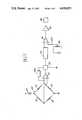
- FIG. 1is a block diagram of the mass flow controller circuit
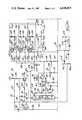
- FIG. 2ais a schematic diagram of a portion of a mass flow controller circuit
- FIG. 2bis a schematic diagram of another portion of the mass flow controller circuit.
- the mass flow controller 10has a constant current generator 12 connected to a bridge 14 for supply of current thereto.
- the bridge 14has a pair of resistors, respectively identified by numerals 16 and 18, which are positioned within a branch tube of a gas flow line.
- the resistor 16 and the resistor 18, in this embodiment, each being comprised of about 50 turns of one ohm per turn resistance wire,are coiled around the branch tube in good heat conducting relation therewith, with the resistor 16 disposed upstream of the resistor 18.
- a bridge amplifier 20having variable gain, preselectable by a user, by varying an impedance in a grounded portion of a feedback loop 22, is connected to the bridge 14 and produces an output signal porportional to the differential change in resistance of the resistors 16 and 18 caused by gas flowing past the resistors 16 and 18.
- the bridge amplifier output signalis supplied to a linearizing network 24 comprised of a plurality of precision limiter circuits.
- Linearizing network 24supplies a substantially linear potential, which is directly proportional to the rate of flow of gas, to a comparator 26.
- a user selectable set point potential, which is selected by movement of a wiper potentiometer 28,is also supplied to the comparator 26.
- a servoamplifier 30receives an output signal from the comparator 26 and supplies a driver current to a well-known solenoidal valve 32, which meters the flow of gas through the gas flow line.
- the constant current generator 12comprises a resistor 40, which is connected at a node 42 to a source of regulated positive 15 volt potential.
- a lead 44supplies the positive 15 volt potential to a reverse biased Zener diode 46 and to a supply rail 48 of an operational amplifier 50.
- a resistor 52is connected to the resistor 40. The resistor 52 feeds an inverting terminal 54 of amplifier 50.
- a noninverting terminal 56 of the operational amplifier 50is connected to the cathode of Zener diode 46 and resistor 58, which is connected to a ground lead 59.
- a regulated positive potential held at 6 volts below the 15 volt supply potential by the Zener diode 46is supplied to the noninverting terminal 56 of the operational amplifier 50.
- a capacitor 60is connected in a feedback loop between an output terminal 62 of the operational amplifier 50 and the inverting input terminal 54 to limit the high frequency gain of the operational amplifier 50 and thereby prevent oscillation of the output signal from the operational amplifier 50.
- the resistor 52limits the current flow to the inverting terminal 54.
- a resistor 64is connected to the output terminal 62 and the electrolytic capacitor 60 to limit current flow into a base 66 of a PNP transistor 68.
- the transistor 68has an emitter 70 connected to the junction of the resistors 40 and 52.
- a collector 72is connected to the bridge 14.
- the operational amplifier 50also has a power supply rail 74 connected through a lead 75 to a negative 15 volt feed point 75a.
- the bridge 14includes the resistors 16 and 18 which comprise two of its legs.
- a fixed resistor 76is connected to resistor 16 and collector 72 of transistor 68.
- a fixed resistor 78is connected to the ground lead 59 and to the resistor 18.
- a potentiometer 80is connected between the resistors 76 and 78. Potentiometer 80 is used to zero the bridge amplifier 20 during a calibration phase of the construction.
- a wiper 82 from potentiometer 80is connected to an inverting terminal 84 of the bridge amplifier 20.
- the bridge amplifier 20includes an operational amplifier 86 having a noninverting terminal 88, which is connected through a fixed resistor 90 to a node 92 intermediate the resistors 16 and 18.
- the upstream resistor 16is preferentially cooled and hence has a lower resistance causing the voltage at the junction of the resistors 16 and 18 to rise with respect to the voltage at the junction of the resistors 76 and 78.
- the more rapid the gas flowthe greater the temperature difference between the resistors 16 and 18.
- the differential cooling effectis no longer detectible and a different gas flow metering system than the one disclosed herein would have to be employed.
- the relative variation in resistances of the resistors 16 and 18unbalances the bridge 14 and supplies a differential input voltage to the input terminals 84 and 88 of the operational amplifier 86.
- the differential voltagedoes not have a linear relationship to the rate of flow of the gas through the branch tube. Since it is necessary to provide very precise adjustment for the rates of flow of the gas, amplifier 86 boosts the differential voltage produced by bridge 14. This amplifier voltage is outputted at an output terminal 92.
- Amplifier 86is configured as a differential amplifier having a resistor 94 connected between the ground lead 59 and the noninverting terminal 88.
- An electrolytic capacitor 96is connected in parallel with resistor 94. Electrolytic capacitor 96 and resistor 94 provide a low impedance ground pathway for high frequency noise that would otherwise be amplified by operational amplifier 86.
- An electrolytic capacitor 98having the same capacitance as electrolytic capacitor 96, and a resistor 100, having the same resistance as resistor 94, are connected in parallel with each other and are connected in a feedback loop 101 between the inverting terminal 84 and the output terminal 92 of the operational amplifier 86.
- the electrolytic capacitor 98 and the resistor 100also limit the high frequency response or the bandwidth of the operational amplifier 86 to prevent spurious noise signals from being amplified.
- Also included within the feedback loopare a fixed resistor 102 and a portion of a potentiometer 104.
- potentiometer 104Since the amount of resistance of potentiometer 104 within the feedback loop 101 is controlled by the user selection of a position of a tap 106, the user may select the relative amount of gain desired from the bridge amplifier 20.
- the potentiometer 104is connected to a fixed resistor 108, which is also connected to the ground 59.
- the response of the electric circuitis much more rapid than the thermal response of bridge 14.
- the relatively slow response of the bridge 14is caused by temperature lag within the sensor resistors 16 and 18.
- an electrolytic capacitor 110is connected to the capacitor 98 and the resistor 100.
- a resistor 112is connected to the electrolytic capacitor 110 and to the ground lead 59. The combination of the electrolytic capacitor 110 and the resistor 112 provides a time shift to the signal supplied by the operational amplifier 86 and compensates for the temperature lag of the bridge 14.
- a ground or common lead 113is connected to lead 59.
- a pair of filter capacitors 114 and 115are connected between common lead 113 and a negative 15 volt power supply lead 116, which is connected to lead 75 and terminates at node 75a.
- a second pair of filter capacitors 117 and 118are connected between common lead 113 and a postive 15 volt supply lead 119, which is connected at a node 120 to a suitable source of regulated positive 15 volt D.C. potential. Lead 119 is also connected to lead 42.
- Capacitors 114 and 117are electrolytic capacitors.
- a lead 122is connected to lead 75 to supply a resistor 124 with a negative 15 volt potential.
- a Zener diode 126is connected between the resistor 124 and the ground lead 59 to provide a regulated negative 6 volt D.C. potential to a supply lead 128.
- a supply lead 128,feeds a supply lead 129, which feeds linearization network 24.
- Linearization network 24includes four precision limiter circuits.
- a first precision limiter circuit 130also referred to herein as the 25% precision limiter, having an operational amplifier 132 with a noninverting terminal 134 connected to ground and an inverting terminal 136 is connected to receive a current from a resistor 138 connected to the lead 93 and a resistor 140.
- the resistor 140is supplied with the negative 6 volt potential from the lead 129.
- the resistor 138is supplied with the output signal from the bridge amplifier 20.
- a feedback resistor 142is connected to the junction of the inverting terminal 136 and resistor 138.
- a diode 144is connected to resistor 142 and to a junction of an output terminal 146 of the operational amplifier 132 and a diode 148.
- the diode 148is connected to a junction of the inverting terminal 136 and resistor 140.
- resistors 138 and 142are each 100 kilohm resistors while resistor 140 is a 499 kilohm resistor.
- Amplifier 132inverts the bridge amplifier signal when the bridge amplifier signal exceeds 1.25 volts. Below 1.25 volts, point diode 144 is back-biased and diode 148 is forward-biased, holding both ends of resistor 142 at ground and effectively removing amplifier 132 from the circuit so that no output signal is provided.
- the gain curve breakpoint for amplifier 132is at 1.25 volts in this embodiment.
- the output signal from bridge amplifier 20is selected to vary between 0 and plus 5 volts over the total range of gas flow rates of interest.
- the breakpoint of amplifier 132occurs at about the 25% flow rate amplitude.
- a second precision limiter 150also referred to herein as the 50% precision limiter, has an operational amplifier 152 having a noninverting input terminal 154 connected to the ground lead 59 and an inverting input terminal 156 connected to a junction of a resistor 158 and a resistor 160.
- a resistor 162is connected in a feedback loop of amplifier 152 between the junction of input terminal 156 and the resistor 158 and a diode 164.
- the diode 164is connected to an output terminal 166 of the operational amplifier 152.
- a diode 168is connected to the junction of the diode 164 and the output terminal 166.
- the diode 168is connected to the junction of the resistor 160 and the inverting input terminal 156.
- the resistor 158receives the bridge amplifier signal from the lead 93.
- the resistor 160receives the regulated negative 6 volt potential from the lead 129.
- the resistors 158 and 162are each 100 kilohm resistors, while the resistor 169 is a 249 kilohm resistor.
- the operational amplifier 152inverts the bridge amplifier signal as long as the bridge amplifier output voltage is greater than positive 2.50 volts.
- the diode 164is back-biased into a blocking state while diode 168 is forward-biased, thereby eliminating the output signal from operational amplifier 152 and effectively removing it from the circuit.
- the gain curve breakpoint for precision limiter 150is at positive 2.50 volts, which in this embodiment corresponds to an ideal gas flow rate of 50%.
- a third precision limiter 170also referred to herein as the 75% precision limiter, having an operational amplifier 172 with a noninverting input terminal 174 connected to ground and an inverting input terminal 176 connected to a junction of a resistor 178 and a resistor 180.
- a feedback resistor 182is connected to the junction of resistor 178 and inverting terminal 176.
- a diode 184is connected to the reesistor 182.
- An output terminal 186 of the operational amplifier 172is connected to the diode 184.
- a diode 188is connected to the junction of the diode 184 and the output terminal 186. The diode 188 is connected to the junction of the resistor 180 and the inverting input terminal 176.
- the resistor 178receives the bridge amplifier signal from the Lead 93 while the resistor 180 receives the regulated negative 6 volt potential from the lead 129.
- the operational amplifier 172inverts the bridge amplifier signal.
- the diode 184is back-biased, the diode 188 is forward-biased and operational amplifier 172 provides no output signal, effectively eliminating it from the circuit.
- the gain curve breakpoint for precision limiter 170is at positive 3.75 volts, which corresponds to 75% of the maximum voltage.
- the 3.75 volt breakpoint and unity inverting gain factorsare determined by the resistances of 100 kilohm resistor 178, 100 kilohm resistor 182 and 165 kilohm resistor 180.
- an operational amplifier 200configured as an inverting amplifier having unity gain is provided herein.
- a resistor 202is connected between the lead 93 and an inverting terminal 204 of the operational amplifier 200.
- the operational amplifier 200also has a noninverting terminal 206 and an output terminal 208.
- a feedback resistor 210is connected between inverting terminal 204 and output terminal 208.
- resistors 202 and 210are identical 100 kilohm resistors.
- the amplifier signalis fed from output terminal 208 through a resistor 212 to a summing point 213.
- amplifiers 132, 152, 172 and 200all provide unity gain inverting functions. The only difference between each of the amplifiers is that the gain curve inflects at positive 1.25 volts for amplifier 132, at positive 2.50 volts for amplifier 152, and at positive 3.75 volts for amplifier 172. The full scale 0.00-5.00 volt range is covered by amplifier 200.
- resistance valuesare selected for an output resistor connected to the output terminal of each of the respective precision limiter circuits.
- an output resistor from each of the precision limiter circuitsis used to feed either the input or output sides of the full scale inverting operational amplifier 200 depending upon the polarity of the correcting voltage.
- the 25%, 50% and 75% flow rate pointswere chosen for calibration, it may be appreciated that additional precision limiters can be added in parallel to provide as many adjustment or calibration points along the flow rate curve as is desirable.
- the correction factors from resistors 214 and 218 in this embodimentare added together at the summing point 213, which is connected through a lead 222 to an inverting input terminal 224 of an operational amplifier 226.
- the operational amplifier 226also has a noninverting input terminal 228 connected to the ground lead 59 and an output terminal 230, which is connected to a feedback resistor 232.
- Feedback resistor 232is connected through a lead 234 to the inverting terminal 224 of operational amplifier 230. It may be appreciated that the selection of the resistance values of resistors 214 and 218, in conjunction with the value of feedback resistor 232, determines the gain for the respective voltages fed through those resistors to summing point 213.
- resistors 214 and 218are shown connected to the input of amplifier 200, while resistor 216 is connected to the input of amplifier 226, it may be appreciated that the calibration measurments may in other cases require different connection combinations to yield piecewise signal linearity.
- the signal fed from amplifier 200 through resistor 213is inverted by the operational amplifier 226 and added to the signal from resistor 216.
- An output sensing terminal 236is connected to output terminal 230, a 100 ohm resistor 238 is connected to output lead 236 for externally monitoring the output voltage from the linearization network 24.
- the linearized voltage signalis fed through a resistor 240 to an inverting input terminal 242 of a comparator consisting of an operational amplifier 246.
- the operational amplifier 246also has a noninverting terminal 248 and an output terminal 250.
- a capacitor 252is connected between input terminal 242 and output terminal 250.
- An exterior voltage setpoint signalis fed through a lead 254 through a resistor 256 and onto a lead 258, which is connected to input terminal 248.
- a filtering networkcomprising a resistor 262 and a capacitor 264 series connected between resistor 256 and the ground lead 59 limits the high frequency response of the operational amplifier 246 by conducting high frequency noise signals preferentially to ground and only allowing the DC setpoint signal to be supplied to the noninverting input terminal 248 of operational amplifier 246.
- the signal from the comparator 26is fed to a resistor 270 connected between the output terminal 250 and the servoamplifier 30.
- the signalis supplied to an NPN transistor 272 at a base 274.
- a collector 276 of transistor 272 and an emitter 278are connected in a Darlington configuration with a PNP power transistor 280.
- a base 282 of the transistor 280is connected to collector 276.
- An emitter 284is connected to a power supply lead.
- a collector 286is connected through an oscillation suppressing capacitor 288 to emitter 278 of transistor 272.
- a biasing resistor 290is connected to the junction of emitter 278 and capacitor 288.
- a transistor protection diode 292is connected between base 274 and emitter 278 of transistor 272 to prevent backbiasing caused damage to the base-emitter Junction of transistor 272.
- Poweris fed to transistor 280 through emitter 284 from a power supply line 294, which is connected to an external source of regulated positive 12 volt DC potential.
- a filtering capacitor 296is connected between emitter 284 and the ground lead 59 to remove high frequency signals from the servoamplifier supply line.
- Collector 286is connected to a feedback loop 298 and is also connected to a valve control lead 300.
- a reverse biased diode 302is also connected to the valve control lead 300, as are a pair of terminals, respectively identified by numerals 304 and 306, which are positioned on opposite sides of diode 302.
- the control valve 32is a well-known electromagnetic solenoidal control valve used for control of gases flowing into a diffusion furnace. It may be appreciated that the amount of current passing through the emitter-collector junction of transistor 284 determines the amount of valve opening of the control valve 32 connected to terminal 304 and 306.
- the signal supplied from comparator 246is amplified by transistor 272 and controls the amount of current flowing through power transistor 280. In turn, the amount of current supplied to the flow control valve 32 determines the gas flow rate through the main.
- diode 302is back-biased to allow current to flow through itself when the magnetic field surrounding the solenoid collapses when power is removed.
- An oscillation suppressing capacitor 310is connected between diode 302 and resistor 290 and performs the same function as the capacitor 288.
- the feedback loop 298includes a capacitor 320 which is series connected with a resistor 322. Resistor 322 is connected to the inverting input terminal 242 of the comparator 246. Due to the fact that the comparator 246 can respond to a greater degree than desired to high frequency components fed through resistor 240, capacitor 252 is provided in the feedback loop 298 to limit the bandwidth or high frequency gain of the operational amplifier 246. Thus, it is desirable to use the feedback loop 298 to control the amount of power being fed directly to the control valve 32 so that the valve adjusts relatively slowly. This is desirable due to the thermal lag present in other parts of the system.
- Feedback loop 298 with its capacitor 320treats comparator 246, transistor 272 and transistor 280 as a single amplifier having a 12 decibel per octave gain curve rolloff. Capacitor 320 is added to the feedback loop to prevent the circuit from oscillating around the rolloff breakpoint.
- the instant inventionprovides a mass flow controller circuit which is sensitive to relatively small changes in the rate of flow of gas through a tube.
- the linearization networkprovides a linear correction at a number of points along a flow rate curve to insure that the voltage fed to comparator 246 is linearly proportional to the rate of flow of gas through the tube.
- the comparator 246has a rapid response to any changes in the amount of error signal for the gas rate flowing through the tube.
- Capacitances 252 and 320limit the high frequency gain of amplifier 246 and the servoamplifier to cause the control valve to adjust position relatively slowly to prevent overshoot of the control valve.
Landscapes
- Physics & Mathematics (AREA)
- General Physics & Mathematics (AREA)
- Engineering & Computer Science (AREA)
- Automation & Control Theory (AREA)
- Measuring Volume Flow (AREA)
Abstract
Description
Claims (12)
Priority Applications (3)
| Application Number | Priority Date | Filing Date | Title |
|---|---|---|---|
| US06/193,876US4658855A (en) | 1980-10-03 | 1980-10-03 | Mass flow controller |
| NL8104478ANL8104478A (en) | 1980-10-03 | 1981-10-01 | MASS FLOW CONTROLLER. |
| DE19813139023DE3139023A1 (en) | 1980-10-03 | 1981-10-01 | QUANTITY CONTROLLER |
Applications Claiming Priority (1)
| Application Number | Priority Date | Filing Date | Title |
|---|---|---|---|
| US06/193,876US4658855A (en) | 1980-10-03 | 1980-10-03 | Mass flow controller |
Publications (1)
| Publication Number | Publication Date |
|---|---|
| US4658855Atrue US4658855A (en) | 1987-04-21 |
Family
ID=22715372
Family Applications (1)
| Application Number | Title | Priority Date | Filing Date |
|---|---|---|---|
| US06/193,876Expired - LifetimeUS4658855A (en) | 1980-10-03 | 1980-10-03 | Mass flow controller |
Country Status (3)
| Country | Link |
|---|---|
| US (1) | US4658855A (en) |
| DE (1) | DE3139023A1 (en) |
| NL (1) | NL8104478A (en) |
Cited By (27)
| Publication number | Priority date | Publication date | Assignee | Title |
|---|---|---|---|---|
| US4777383A (en)* | 1987-06-01 | 1988-10-11 | Ldi Pneutronics Corp. | Electrically controlled variable pressure pneumatic circuit |
| US4909078A (en)* | 1987-10-14 | 1990-03-20 | Rosemount Inc. | Fluid flow detector |
| US4934397A (en)* | 1987-06-18 | 1990-06-19 | Halton Oy | Procedure and means for controlling volumetric flow rate in air-conditioning installations |
| US5141021A (en)* | 1991-09-06 | 1992-08-25 | Stec Inc. | Mass flow meter and mass flow controller |
| US5203537A (en)* | 1992-03-09 | 1993-04-20 | Teledyne Industries, Inc. | Piezoceramic valve actuator sandwich assembly and valve incorporating such an assembly |
| WO1993025950A1 (en)* | 1992-06-12 | 1993-12-23 | Unit Instruments, Inc. | Mass flow controller |
| US5768883A (en)* | 1996-01-25 | 1998-06-23 | Ametek Aerospace Products Inc. | Flowrate control sytem and method |
| US6247493B1 (en) | 2000-03-09 | 2001-06-19 | Richard C. Henderson | Miniature pulsatile flow controller |
| US20020198668A1 (en)* | 2001-04-24 | 2002-12-26 | Lull John M. | System and method for a mass flow controller |
| US20040074311A1 (en)* | 2002-07-19 | 2004-04-22 | Celerity Group, Inc. | Methods and apparatus for pressure compensation in a mass flow controller |
| US6799603B1 (en)* | 1999-09-20 | 2004-10-05 | Moore Epitaxial, Inc. | Gas flow controller system |
| US20050288825A1 (en)* | 2004-07-08 | 2005-12-29 | Tinsley Kenneth E | Method and system for a mass flow controller with reduced pressure sensitivity |
| US20080211510A1 (en)* | 2007-03-01 | 2008-09-04 | Michael John Zolock | Method and apparatus for measuring the temperature of a gas in a mass flow controller |
| US20080295892A1 (en)* | 2007-06-04 | 2008-12-04 | Horiba Stec, Co., Ltd. | Mass flow controller |
| US20100080262A1 (en)* | 2008-09-26 | 2010-04-01 | Advanced Energy Industries, Inc. | Method and system for operating a mass flow controller |
| US20100089459A1 (en)* | 2008-10-13 | 2010-04-15 | Advanced Energy Industries, Inc. | Mass flow controller and method of operating the same |
| US20120180877A1 (en)* | 2011-01-03 | 2012-07-19 | Scott Pallais | Non-invasive Thermal Dispersion Flow Meter with Chronometric Monitor for Fluid Leak Detection |
| CN104545827A (en)* | 2014-12-23 | 2015-04-29 | 金陵科技学院 | Body temperature detection circuit and thermometer comprising body temperature detection circuit |
| US20150309521A1 (en)* | 2014-04-29 | 2015-10-29 | Yang Pan | Cloud Based Power Management System |
| US20170045482A1 (en)* | 2014-02-17 | 2017-02-16 | Shimadzu Corporation | Feedback control device |
| US20170160753A1 (en)* | 2015-12-04 | 2017-06-08 | Asco Numatics Gmbh | Pilot control unit, valve arrangement, and method for the regulated provision of a fluid |
| US11162602B2 (en)* | 2019-06-07 | 2021-11-02 | Horiba Stec, Co., Ltd. | Fluid control valve, flow rate control device, and drive circuit |
| JPWO2022209719A1 (en)* | 2021-03-31 | 2022-10-06 | ||
| US11608618B2 (en) | 2011-01-03 | 2023-03-21 | Sentinel Hydrosolutions, Llc | Thermal dispersion flow meter with fluid leak detection and freeze burst prevention |
| US11814821B2 (en) | 2011-01-03 | 2023-11-14 | Sentinel Hydrosolutions, Llc | Non-invasive thermal dispersion flow meter with fluid leak detection and geo-fencing control |
| US12436206B2 (en) | 2021-03-31 | 2025-10-07 | Murata Manufacturing Co., Ltd. | Sensor output compensation circuit |
| US12436207B2 (en) | 2021-03-31 | 2025-10-07 | Murata Manufacturing Co., Ltd. | Sensor output compensation circuit |
Families Citing this family (1)
| Publication number | Priority date | Publication date | Assignee | Title |
|---|---|---|---|---|
| US4685331A (en)* | 1985-04-10 | 1987-08-11 | Innovus | Thermal mass flowmeter and controller |
Citations (13)
| Publication number | Priority date | Publication date | Assignee | Title |
|---|---|---|---|---|
| DE876484C (en)* | 1942-10-18 | 1953-05-15 | Basf Ag | Hot wire flow meter |
| US3372590A (en)* | 1965-10-01 | 1968-03-12 | Technology Inc | Thermal flowmeter |
| US3559480A (en)* | 1968-12-20 | 1971-02-02 | Leeds & Northrup Co | Multirange flowmeter with automatic meter sequencing |
| US3650151A (en)* | 1970-11-18 | 1972-03-21 | Tylan Corp | Fluid flow measuring system |
| US3650505A (en)* | 1970-03-02 | 1972-03-21 | Tylan Corp | Thermal valve |
| US3792609A (en)* | 1971-05-10 | 1974-02-19 | Tylan Corp | Flow splitter |
| US3805610A (en)* | 1972-06-23 | 1974-04-23 | Emerson Electric Co | Flow dividing means, particularly for thermal flowmeter |
| US3851526A (en)* | 1973-04-09 | 1974-12-03 | Tylan Corp | Fluid flowmeter |
| US3938384A (en)* | 1972-10-13 | 1976-02-17 | Tylan Corporation | Mass flow meter with reduced attitude sensitivity |
| US3939858A (en)* | 1974-09-13 | 1976-02-24 | Tylan Corporation | Assembly and method of obtaining a controlled gas mixture |
| US4056975A (en)* | 1976-02-09 | 1977-11-08 | Tylan Corporation | Mass flow sensor system |
| US4100801A (en)* | 1976-02-09 | 1978-07-18 | Tylan Corporation | Mass flow sensing system |
| US4255968A (en)* | 1979-06-08 | 1981-03-17 | Intek, Inc. | Flow indicator |
Family Cites Families (3)
| Publication number | Priority date | Publication date | Assignee | Title |
|---|---|---|---|---|
| DE858777C (en)* | 1941-07-13 | 1952-12-08 | Basf Ag | Device for gas analysis by measuring the heat conductivity |
| US3552428A (en)* | 1968-06-20 | 1971-01-05 | Phillips Petroleum Co | Automatically tuned process controller |
| US3757808A (en)* | 1972-07-21 | 1973-09-11 | Garrett Corp | Electronic mass airflow sensing and control system |
- 1980
- 1980-10-03USUS06/193,876patent/US4658855A/ennot_activeExpired - Lifetime
- 1981
- 1981-10-01NLNL8104478Apatent/NL8104478A/ennot_activeApplication Discontinuation
- 1981-10-01DEDE19813139023patent/DE3139023A1/ennot_activeWithdrawn
Patent Citations (13)
| Publication number | Priority date | Publication date | Assignee | Title |
|---|---|---|---|---|
| DE876484C (en)* | 1942-10-18 | 1953-05-15 | Basf Ag | Hot wire flow meter |
| US3372590A (en)* | 1965-10-01 | 1968-03-12 | Technology Inc | Thermal flowmeter |
| US3559480A (en)* | 1968-12-20 | 1971-02-02 | Leeds & Northrup Co | Multirange flowmeter with automatic meter sequencing |
| US3650505A (en)* | 1970-03-02 | 1972-03-21 | Tylan Corp | Thermal valve |
| US3650151A (en)* | 1970-11-18 | 1972-03-21 | Tylan Corp | Fluid flow measuring system |
| US3792609A (en)* | 1971-05-10 | 1974-02-19 | Tylan Corp | Flow splitter |
| US3805610A (en)* | 1972-06-23 | 1974-04-23 | Emerson Electric Co | Flow dividing means, particularly for thermal flowmeter |
| US3938384A (en)* | 1972-10-13 | 1976-02-17 | Tylan Corporation | Mass flow meter with reduced attitude sensitivity |
| US3851526A (en)* | 1973-04-09 | 1974-12-03 | Tylan Corp | Fluid flowmeter |
| US3939858A (en)* | 1974-09-13 | 1976-02-24 | Tylan Corporation | Assembly and method of obtaining a controlled gas mixture |
| US4056975A (en)* | 1976-02-09 | 1977-11-08 | Tylan Corporation | Mass flow sensor system |
| US4100801A (en)* | 1976-02-09 | 1978-07-18 | Tylan Corporation | Mass flow sensing system |
| US4255968A (en)* | 1979-06-08 | 1981-03-17 | Intek, Inc. | Flow indicator |
Non-Patent Citations (26)
| Title |
|---|
| A group exhibit consisting of a plurality of bills of materials and drawings generated by applicant prior to the invention of instant application (12 drawings consisting of 37 pages).* |
| Brochure dated Jun. 1977 entitled "Installation and Operating Instructions, Brooks Thermal Mass Flow Controller Model 5858", identified as Document No. X-5858 (18 pages). |
| Brochure dated Jun. 1977 entitled Installation and Operating Instructions, Brooks Thermal Mass Flow Controller Model 5858 , identified as Document No. X 5858 (18 pages).* |
| Document dated Feb. 1975 entitled "Operation and Service Manual Model FC260 Mass Flow Controller", from the Tylan Corporation (24 pages). |
| Document dated Feb. 1975 entitled Operation and Service Manual Model FC260 Mass Flow Controller , from the Tylan Corporation (24 pages).* |
| Document entitled "AFC-550 Automatic Flow Controller", bearing a copyright notice dated 1971 (24 pages). |
| Document entitled "Installation and Operating Instructions, Brooks Thermal Mass Flowmeter and Thermal Mass Flow Controller", dated Jan. 1979, identified as Document X-5810 (14 pages). |
| Document entitled "Operation and Service Manual, Models FM-360 and FM-361 Mass Flowmeters", from the Tylan Corp. (26 pages). |
| Document entitled AFC 550 Automatic Flow Controller , bearing a copyright notice dated 1971 (24 pages).* |
| Document entitled Installation and Operating Instructions, Brooks Thermal Mass Flowmeter and Thermal Mass Flow Controller , dated Jan. 1979, identified as Document X 5810 (14 pages).* |
| Document entitled Operation and Service Manual, Models FM 360 and FM 361 Mass Flowmeters , from the Tylan Corp. (26 pages).* |
| Document generated by applicant entitled "MFC/Meter/Calibration", dated 2-4-76 (4 pages). |
| Document generated by applicant entitled MFC/Meter/Calibration , dated 2 4 76 (4 pages).* |
| Photocopy of Chapter 7, "Operational Amplifiers Design and Applications", published in 1971 (20 pages). |
| Photocopy of Chapter 7, Operational Amplifiers Design and Applications , published in 1971 (20 pages).* |
| Undated and untitled document apparently from the Tylan Corp., which describes a Tylan GP 481 Hyoxcl Burnt Hydrogen Gas Control Panel (9 pages).* |
| Undated and untitled document apparently from the Tylan Corp., which describes a Tylan GP-481 Hyoxcl "Burnt Hydrogen" Gas Control Panel (9 pages). |
| Undated document entitled "Procedure Assembly-TFC772", generated by applicant (7 pages). |
| Undated document entitled Procedure Assembly TFC772 , generated by applicant (7 pages).* |
| Undated document generated by applicant entitled "Thermco Products Corporation Mass Flow Controller Model TFC772" (14 pages). |
| Undated document generated by applicant entitled Thermco Products Corporation Mass Flow Controller Model TFC772 (14 pages).* |
| Untitled, undated document having subtitle "Single Op Amp Often Insufficient" (36 pages). |
| Untitled, undated document having subtitle Single Op Amp Often Insufficient (36 pages).* |
| Untitled, undated document numbered respectively 96S, 101S, 103S, 104S, 105S and 326S, apparently provided by Analog Devices, Inc. (6 pages).* |
| Untitled, undated sheet bearing the statement "Industry's First $49 D.P.M." (1 page). |
| Untitled, undated sheet bearing the statement Industry s First $49 D.P.M. (1 page).* |
Cited By (53)
| Publication number | Priority date | Publication date | Assignee | Title |
|---|---|---|---|---|
| US4777383A (en)* | 1987-06-01 | 1988-10-11 | Ldi Pneutronics Corp. | Electrically controlled variable pressure pneumatic circuit |
| US4934397A (en)* | 1987-06-18 | 1990-06-19 | Halton Oy | Procedure and means for controlling volumetric flow rate in air-conditioning installations |
| US4909078A (en)* | 1987-10-14 | 1990-03-20 | Rosemount Inc. | Fluid flow detector |
| US5141021A (en)* | 1991-09-06 | 1992-08-25 | Stec Inc. | Mass flow meter and mass flow controller |
| US5203537A (en)* | 1992-03-09 | 1993-04-20 | Teledyne Industries, Inc. | Piezoceramic valve actuator sandwich assembly and valve incorporating such an assembly |
| WO1993025950A1 (en)* | 1992-06-12 | 1993-12-23 | Unit Instruments, Inc. | Mass flow controller |
| US5768883A (en)* | 1996-01-25 | 1998-06-23 | Ametek Aerospace Products Inc. | Flowrate control sytem and method |
| US6799603B1 (en)* | 1999-09-20 | 2004-10-05 | Moore Epitaxial, Inc. | Gas flow controller system |
| US6247493B1 (en) | 2000-03-09 | 2001-06-19 | Richard C. Henderson | Miniature pulsatile flow controller |
| US20020198668A1 (en)* | 2001-04-24 | 2002-12-26 | Lull John M. | System and method for a mass flow controller |
| US7114511B2 (en) | 2001-04-24 | 2006-10-03 | Celerity Group, Inc. | System and method for a mass flow controller |
| US20050167627A1 (en)* | 2001-04-24 | 2005-08-04 | Lull John M. | System and method for a mass flow controller |
| US20050166968A1 (en)* | 2001-04-24 | 2005-08-04 | Lull John M. | System and method for a mass flow controller |
| US7380564B2 (en) | 2001-04-24 | 2008-06-03 | Celerity, Inc. | System and method for a mass flow controller |
| US6962164B2 (en)* | 2001-04-24 | 2005-11-08 | Celerity Group, Inc. | System and method for a mass flow controller |
| US20070215206A1 (en)* | 2001-04-24 | 2007-09-20 | Celerity, Inc. | System and method for a mass flow controller |
| US7231931B2 (en) | 2001-04-24 | 2007-06-19 | Celerity, Inc. | System and method for a mass flow controller |
| US20090078055A1 (en)* | 2002-07-19 | 2009-03-26 | Celerity, Inc. | Methods and apparatus for pressure compensation in a mass flow controller |
| US7073392B2 (en) | 2002-07-19 | 2006-07-11 | Celerity, Inc. | Methods and apparatus for pressure compensation in a mass flow controller |
| US7273063B2 (en) | 2002-07-19 | 2007-09-25 | Celerity, Inc. | Methods and apparatus for pressure compensation in a mass flow controller |
| US20070288180A1 (en)* | 2002-07-19 | 2007-12-13 | Celerity, Inc. | Methods and apparatus for pressure compensation in a mass flow controller |
| US20050223813A1 (en)* | 2002-07-19 | 2005-10-13 | Celerity Group, Inc. | Methods and apparatus for pressure compensation in a mass flow controller |
| US7434477B2 (en) | 2002-07-19 | 2008-10-14 | Celerity, Inc. | Methods and apparatus for pressure compensation in a mass flow controller |
| US8751180B2 (en) | 2002-07-19 | 2014-06-10 | Brooks Instrument Llc | Methods and apparatus for pressure compensation in a mass flow controller |
| US20040074311A1 (en)* | 2002-07-19 | 2004-04-22 | Celerity Group, Inc. | Methods and apparatus for pressure compensation in a mass flow controller |
| US7216019B2 (en) | 2004-07-08 | 2007-05-08 | Celerity, Inc. | Method and system for a mass flow controller with reduced pressure sensitivity |
| US20050288825A1 (en)* | 2004-07-08 | 2005-12-29 | Tinsley Kenneth E | Method and system for a mass flow controller with reduced pressure sensitivity |
| US20080211510A1 (en)* | 2007-03-01 | 2008-09-04 | Michael John Zolock | Method and apparatus for measuring the temperature of a gas in a mass flow controller |
| US7651263B2 (en) | 2007-03-01 | 2010-01-26 | Advanced Energy Industries, Inc. | Method and apparatus for measuring the temperature of a gas in a mass flow controller |
| US20080295892A1 (en)* | 2007-06-04 | 2008-12-04 | Horiba Stec, Co., Ltd. | Mass flow controller |
| US8056579B2 (en)* | 2007-06-04 | 2011-11-15 | Horiba Stec, Co., Ltd. | Mass flow controller |
| US7826986B2 (en) | 2008-09-26 | 2010-11-02 | Advanced Energy Industries, Inc. | Method and system for operating a mass flow controller |
| US20100080262A1 (en)* | 2008-09-26 | 2010-04-01 | Advanced Energy Industries, Inc. | Method and system for operating a mass flow controller |
| US20100089459A1 (en)* | 2008-10-13 | 2010-04-15 | Advanced Energy Industries, Inc. | Mass flow controller and method of operating the same |
| US7971480B2 (en)* | 2008-10-13 | 2011-07-05 | Hitachi Metals, Ltd. | Mass flow controller having a first pair of thermal sensing elements opposing a second pair of thermal sensing elements |
| TWI472729B (en)* | 2008-10-13 | 2015-02-11 | Hitachi Metals Ltd | Mass flow controller and method of operating the same |
| US20120180877A1 (en)* | 2011-01-03 | 2012-07-19 | Scott Pallais | Non-invasive Thermal Dispersion Flow Meter with Chronometric Monitor for Fluid Leak Detection |
| US11608618B2 (en) | 2011-01-03 | 2023-03-21 | Sentinel Hydrosolutions, Llc | Thermal dispersion flow meter with fluid leak detection and freeze burst prevention |
| US9146172B2 (en)* | 2011-01-03 | 2015-09-29 | Sentinel Hydrosolutions, Llc | Non-invasive thermal dispersion flow meter with chronometric monitor for fluid leak detection |
| US10364555B2 (en) | 2011-01-03 | 2019-07-30 | Sentinel Hydrosolutions, Llc | Thermal monitor clamp and method for detecting the temperature of a fluid within a conduit |
| US12320102B2 (en) | 2011-01-03 | 2025-06-03 | Sentinel Hydrosolutions, Llc | Thermal dispersion flow meter with fluid leak detection and freeze burst prevention |
| US12006667B2 (en) | 2011-01-03 | 2024-06-11 | Sentinel Hydrosolutions, Llc | Fluid leak detector with thermal dispersion flow meter and chronometric monitor |
| US11814821B2 (en) | 2011-01-03 | 2023-11-14 | Sentinel Hydrosolutions, Llc | Non-invasive thermal dispersion flow meter with fluid leak detection and geo-fencing control |
| US20170045482A1 (en)* | 2014-02-17 | 2017-02-16 | Shimadzu Corporation | Feedback control device |
| US10184919B2 (en)* | 2014-02-17 | 2019-01-22 | Shimadzu Corporation | Feedback control apparatus |
| US20150309521A1 (en)* | 2014-04-29 | 2015-10-29 | Yang Pan | Cloud Based Power Management System |
| CN104545827A (en)* | 2014-12-23 | 2015-04-29 | 金陵科技学院 | Body temperature detection circuit and thermometer comprising body temperature detection circuit |
| US20170160753A1 (en)* | 2015-12-04 | 2017-06-08 | Asco Numatics Gmbh | Pilot control unit, valve arrangement, and method for the regulated provision of a fluid |
| US10663983B2 (en)* | 2015-12-04 | 2020-05-26 | Asco Numatics Gmbh | Pilot control unit, valve arrangement, and method for the regulated provision of a fluid |
| US11162602B2 (en)* | 2019-06-07 | 2021-11-02 | Horiba Stec, Co., Ltd. | Fluid control valve, flow rate control device, and drive circuit |
| JPWO2022209719A1 (en)* | 2021-03-31 | 2022-10-06 | ||
| US12436206B2 (en) | 2021-03-31 | 2025-10-07 | Murata Manufacturing Co., Ltd. | Sensor output compensation circuit |
| US12436207B2 (en) | 2021-03-31 | 2025-10-07 | Murata Manufacturing Co., Ltd. | Sensor output compensation circuit |
Also Published As
| Publication number | Publication date |
|---|---|
| DE3139023A1 (en) | 1982-06-24 |
| NL8104478A (en) | 1982-05-03 |
Similar Documents
| Publication | Publication Date | Title |
|---|---|---|
| US4658855A (en) | Mass flow controller | |
| US3988928A (en) | Device for measuring and/or monitoring the flow velocity of a flowing fluid | |
| EP0147573B1 (en) | Air flow meter circuit with temperature compensation circuit | |
| KR100326479B1 (en) | Differential current thermal mass flow transducer | |
| US4516865A (en) | Resistance thermometer | |
| US4686856A (en) | Mass flow meter | |
| US5345184A (en) | Humidity detection circuit for electronic heat cooking apparatus | |
| JP2522337Y2 (en) | Flow meter with thermal resistance element | |
| US5212983A (en) | Air flow sensor and detecting method | |
| US4888471A (en) | An improvement in a device for high accuracy thermal regulations of an enclosure | |
| KR100318039B1 (en) | Exothermic Resistance Air Flow Meter | |
| US4592665A (en) | Temperature-controlled systems for non-thermal parameter measurements | |
| US5181420A (en) | Hot wire air flow meter | |
| US4190796A (en) | Pressure detecting apparatus having linear output characteristic | |
| US4201088A (en) | Differential measuring system | |
| KR960006308B1 (en) | Thermosetting flowmeter | |
| US4379520A (en) | Temperature regulating system for air conditioning or heating plants, preferably in railway vehicles | |
| US4748852A (en) | Transmitter with an improved span adjustment | |
| KR20020042798A (en) | Improved mass flow sensor interface circuit | |
| US3968685A (en) | Transistor anemometer | |
| US4684886A (en) | Automatic equalizer | |
| US20050222782A1 (en) | Flow monitoring system | |
| JPS5864510A (en) | Mass flowrate controller | |
| JPH03172717A (en) | Flowmeter | |
| JPS62249014A (en) | Symmetric bridge circuit measuring mass flow of air |
Legal Events
| Date | Code | Title | Description |
|---|---|---|---|
| AS | Assignment | Owner name:THERMCO SYSTEMS, INC. Free format text:CHANGE OF NAME;ASSIGNOR:THERMCO PRODUCTS CORPORATION;REEL/FRAME:004359/0602 Effective date:19840618 | |
| STCF | Information on status: patent grant | Free format text:PATENTED CASE | |
| AS | Assignment | Owner name:ANICON, INC., A CORP. OF CA., CALIFORNIA Free format text:ASSIGNMENT OF ASSIGNORS INTEREST.;ASSIGNOR:THERMCO SYSTEMS, INC.;REEL/FRAME:005009/0076 Effective date:19881215 | |
| AS | Assignment | Owner name:ANICON, INC., CALIFORNIA Free format text:ASSIGNMENT OF ASSIGNORS INTEREST.;ASSIGNOR:THERMCO SYSTEMS, INC.;REEL/FRAME:005178/0909 Effective date:19881215 | |
| AS | Assignment | Owner name:BANK OF AMERICA NATIONAL TRUST AND SAVINGS ASSOCIA Free format text:SECURITY INTEREST;ASSIGNOR:SILICON VALLEY GROUP, INC.;REEL/FRAME:005443/0382 Effective date:19900515 | |
| AS | Assignment | Owner name:THERMCO SYSTEMS, INC. Free format text:CHANGE OF NAME;ASSIGNOR:ANICON, INC.,;REEL/FRAME:005404/0482 Effective date:19890726 Owner name:SILICON VALLEY GROUP, INC. Free format text:MERGER;ASSIGNOR:THERMCO SYSTEMS, INC., A CORP OF CA;REEL/FRAME:005404/0458 Effective date:19900322 Owner name:SILICON VALLEY GROUP, INC. Free format text:MERGER;ASSIGNOR:THERMCO SYSTEMS, INC., A CORP OF CA;REEL/FRAME:005404/0469 Effective date:19900322 | |
| AS | Assignment | Owner name:BANK OF AMERICA NATIONAL TRUST AND SAVINGS ASSOCIA Free format text:SECURITY INTEREST;ASSIGNOR:SILICON VALLEY GROUP, IN.,;REEL/FRAME:005458/0172 Effective date:19900905 | |
| AS | Assignment | Owner name:SILICON VALLEY GROUP, INC., CALIFORNIA Free format text:RELEASED BY SECURED PARTY;ASSIGNOR:BANK OF AMERICA NATIONAL TRUST AND SAVINGS ASSOCIATION;REEL/FRAME:006396/0698 Effective date:19921103 | |
| AS | Assignment | Owner name:BARCLAYS BANK PLC, AS COLLATERAL AGENT, CALIFORNIA Free format text:SECURITY INTEREST;ASSIGNOR:SILICON VALLEY GROUP, INC.;REEL/FRAME:006437/0257 Effective date:19921103 | |
| AS | Assignment | Owner name:SILICON VALLEY GROUP, INC., CALIFORNIA Free format text:RELEASE OF SECURITY INTEREST;ASSIGNOR:BARCLAYS BANK PLC, AS COLLATERAL AGENT;REEL/FRAME:007179/0198 Effective date:19941011 Owner name:ABN AMRO BANK N.V., AS AGENT, CALIFORNIA Free format text:SECURITY INTEREST;ASSIGNOR:SILICON VALLEY GROUP, INC.;REEL/FRAME:007179/0189 Effective date:19941007 | |
| CC | Certificate of correction | ||
| AS | Assignment | Owner name:TETREON TECHNOLOGIES LIMITED, UNITED KINGDOM Free format text:ASSIGNMENT OF ASSIGNORS INTEREST;ASSIGNOR:AVIZA TECHNOLOGY, INC.;REEL/FRAME:016038/0772 Effective date:20041101 |