US4658290A - Television and market research data collection system and method - Google Patents
Television and market research data collection system and methodDownload PDFInfo
- Publication number
- US4658290A US4658290AUS06/658,378US65837884AUS4658290AUS 4658290 AUS4658290 AUS 4658290AUS 65837884 AUS65837884 AUS 65837884AUS 4658290 AUS4658290 AUS 4658290A
- Authority
- US
- United States
- Prior art keywords
- data
- data collection
- collection unit
- channel
- control means
- Prior art date
- Legal status (The legal status is an assumption and is not a legal conclusion. Google has not performed a legal analysis and makes no representation as to the accuracy of the status listed.)
- Expired - Lifetime
Links
Images


Classifications
- H—ELECTRICITY
- H04—ELECTRIC COMMUNICATION TECHNIQUE
- H04N—PICTORIAL COMMUNICATION, e.g. TELEVISION
- H04N7/00—Television systems
- H04N7/16—Analogue secrecy systems; Analogue subscription systems
- H04N7/173—Analogue secrecy systems; Analogue subscription systems with two-way working, e.g. subscriber sending a programme selection signal
- H04N7/17309—Transmission or handling of upstream communications
- H04N7/17327—Transmission or handling of upstream communications with deferred transmission or handling of upstream communications
- G—PHYSICS
- G06—COMPUTING OR CALCULATING; COUNTING
- G06Q—INFORMATION AND COMMUNICATION TECHNOLOGY [ICT] SPECIALLY ADAPTED FOR ADMINISTRATIVE, COMMERCIAL, FINANCIAL, MANAGERIAL OR SUPERVISORY PURPOSES; SYSTEMS OR METHODS SPECIALLY ADAPTED FOR ADMINISTRATIVE, COMMERCIAL, FINANCIAL, MANAGERIAL OR SUPERVISORY PURPOSES, NOT OTHERWISE PROVIDED FOR
- G06Q30/00—Commerce
- G06Q30/02—Marketing; Price estimation or determination; Fundraising
- G—PHYSICS
- G06—COMPUTING OR CALCULATING; COUNTING
- G06Q—INFORMATION AND COMMUNICATION TECHNOLOGY [ICT] SPECIALLY ADAPTED FOR ADMINISTRATIVE, COMMERCIAL, FINANCIAL, MANAGERIAL OR SUPERVISORY PURPOSES; SYSTEMS OR METHODS SPECIALLY ADAPTED FOR ADMINISTRATIVE, COMMERCIAL, FINANCIAL, MANAGERIAL OR SUPERVISORY PURPOSES, NOT OTHERWISE PROVIDED FOR
- G06Q50/00—Information and communication technology [ICT] specially adapted for implementation of business processes of specific business sectors, e.g. utilities or tourism
- G06Q50/10—Services
- H—ELECTRICITY
- H04—ELECTRIC COMMUNICATION TECHNIQUE
- H04H—BROADCAST COMMUNICATION
- H04H60/00—Arrangements for broadcast applications with a direct linking to broadcast information or broadcast space-time; Broadcast-related systems
- H04H60/29—Arrangements for monitoring broadcast services or broadcast-related services
- H04H60/32—Arrangements for monitoring conditions of receiving stations, e.g. malfunction or breakdown of receiving stations
- H—ELECTRICITY
- H04—ELECTRIC COMMUNICATION TECHNIQUE
- H04H—BROADCAST COMMUNICATION
- H04H60/00—Arrangements for broadcast applications with a direct linking to broadcast information or broadcast space-time; Broadcast-related systems
- H04H60/35—Arrangements for identifying or recognising characteristics with a direct linkage to broadcast information or to broadcast space-time, e.g. for identifying broadcast stations or for identifying users
- H04H60/38—Arrangements for identifying or recognising characteristics with a direct linkage to broadcast information or to broadcast space-time, e.g. for identifying broadcast stations or for identifying users for identifying broadcast time or space
- H04H60/41—Arrangements for identifying or recognising characteristics with a direct linkage to broadcast information or to broadcast space-time, e.g. for identifying broadcast stations or for identifying users for identifying broadcast time or space for identifying broadcast space, i.e. broadcast channels, broadcast stations or broadcast areas
- H04H60/43—Arrangements for identifying or recognising characteristics with a direct linkage to broadcast information or to broadcast space-time, e.g. for identifying broadcast stations or for identifying users for identifying broadcast time or space for identifying broadcast space, i.e. broadcast channels, broadcast stations or broadcast areas for identifying broadcast channels
- H—ELECTRICITY
- H04—ELECTRIC COMMUNICATION TECHNIQUE
- H04H—BROADCAST COMMUNICATION
- H04H60/00—Arrangements for broadcast applications with a direct linking to broadcast information or broadcast space-time; Broadcast-related systems
- H04H60/35—Arrangements for identifying or recognising characteristics with a direct linkage to broadcast information or to broadcast space-time, e.g. for identifying broadcast stations or for identifying users
- H04H60/45—Arrangements for identifying or recognising characteristics with a direct linkage to broadcast information or to broadcast space-time, e.g. for identifying broadcast stations or for identifying users for identifying users
- H—ELECTRICITY
- H04—ELECTRIC COMMUNICATION TECHNIQUE
- H04M—TELEPHONIC COMMUNICATION
- H04M11/00—Telephonic communication systems specially adapted for combination with other electrical systems
- H04M11/002—Telephonic communication systems specially adapted for combination with other electrical systems with telemetering systems
- H—ELECTRICITY
- H04—ELECTRIC COMMUNICATION TECHNIQUE
- H04N—PICTORIAL COMMUNICATION, e.g. TELEVISION
- H04N21/00—Selective content distribution, e.g. interactive television or video on demand [VOD]
- H04N21/20—Servers specifically adapted for the distribution of content, e.g. VOD servers; Operations thereof
- H04N21/25—Management operations performed by the server for facilitating the content distribution or administrating data related to end-users or client devices, e.g. end-user or client device authentication, learning user preferences for recommending movies
- H04N21/258—Client or end-user data management, e.g. managing client capabilities, user preferences or demographics, processing of multiple end-users preferences to derive collaborative data
- H04N21/25866—Management of end-user data
- H04N21/25891—Management of end-user data being end-user preferences
- H—ELECTRICITY
- H04—ELECTRIC COMMUNICATION TECHNIQUE
- H04N—PICTORIAL COMMUNICATION, e.g. TELEVISION
- H04N21/00—Selective content distribution, e.g. interactive television or video on demand [VOD]
- H04N21/40—Client devices specifically adapted for the reception of or interaction with content, e.g. set-top-box [STB]; Operations thereof
- H04N21/43—Processing of content or additional data, e.g. demultiplexing additional data from a digital video stream; Elementary client operations, e.g. monitoring of home network or synchronising decoder's clock; Client middleware
- H04N21/442—Monitoring of processes or resources, e.g. detecting the failure of a recording device, monitoring the downstream bandwidth, the number of times a movie has been viewed, the storage space available from the internal hard disk
- H04N21/44213—Monitoring of end-user related data
- H04N21/44222—Analytics of user selections, e.g. selection of programs or purchase activity
- H—ELECTRICITY
- H04—ELECTRIC COMMUNICATION TECHNIQUE
- H04N—PICTORIAL COMMUNICATION, e.g. TELEVISION
- H04N21/00—Selective content distribution, e.g. interactive television or video on demand [VOD]
- H04N21/80—Generation or processing of content or additional data by content creator independently of the distribution process; Content per se
- H04N21/81—Monomedia components thereof
- H04N21/812—Monomedia components thereof involving advertisement data
- H—ELECTRICITY
- H04—ELECTRIC COMMUNICATION TECHNIQUE
- H04N—PICTORIAL COMMUNICATION, e.g. TELEVISION
- H04N7/00—Television systems
- H04N7/16—Analogue secrecy systems; Analogue subscription systems
- H04N7/173—Analogue secrecy systems; Analogue subscription systems with two-way working, e.g. subscriber sending a programme selection signal
- H04N2007/1739—Analogue secrecy systems; Analogue subscription systems with two-way working, e.g. subscriber sending a programme selection signal the upstream communication being transmitted via a separate link, e.g. telephone line
Definitions
- the present inventionrelates to data storage and transmission systems and more particularly relates to monitoring systems for accumulating data at remote locations and transmitting the data to a central location. More particularly, the present invention relates to a data collection system and method for collecting at remote panelist locations data relative to television viewing habits and preferences as well as product purchases and preferences of a plurality of panelists, and transmitting the collected data to a central location.
- a data collection systemis provided in which individual television receivers may be controlled from a central location to display substitute programming.
- the prior artalso includes such systems in which a memory means is provided at the remote location, i.e. at the television receiver, for accumulating data as to the channel being viewed and time. The accumulated data is then periodically transmitted over conventional telephone lines from the remote locations to the central location, by telephone calls initiated by either the remote stations or the central location.
- the store's computercan automatically retain such purchase data for subsequent transfer to a market research company computer data base for correlation with the data regarding the various panelists viewing of commercials.
- Such arrangementsrequire cooperation of stores within the area of the panelist locations, and are therefore more suited for limited geographic groupings of panelists in a single locale or city, and are not readily applicable to a national assemblage of panelists extending across an entire country.
- an auxiliary television signalis broadcast which contains not only substitute programming, i.e. video signal information, but also control information such as pulse code information for remotely selecting panelists which are to receive the substitute programming.
- Digital address informationis provided for each of the panelists, and the portion of the panelists which are to receive the substitute programming are selected by the pulse code information.
- the Walker et al patentnotes that in selecting the panelists which are to receive the substitute programming, the number of categories available is dependent on the number of digital information bits that are incorporated in the system.
- a later U.S. Pat. No. 4,331,974 to Cogswell et alalso discloses an arrangement for selecting portions of a viewing audience on a dynamic basis and furnishing those portions with substitute programming.
- the present inventionrelates to an improved system and method which is of particular utility in market research type applications, but which is not limited thereto.
- a remote data collection unitis provided at each of a plurality of panelist locations.
- the remote unitis adapted to be coupled to one or more television receivers at each panelist location, or to one or more cable television converters in the context of a cable television system.
- the data collection unitincludes a memory and means for monitoring and storing information regarding which of a plurality of television modes are in use, as well as viewer identification data. Means are provided to monitor and store events concerning television viewing, such as channel changes or the like. Further, the data collection unit includes means for optically scanning bar codes and the like and storing information regarding same. Such bar codes and the like can be representative of product purchase information or panelist responses to market research surveys and the like.
- telephone communicationis periodically established between a central location and each of the remote units, and the contents of each data collection unit memory are transmitted to the central location.
- a portable memory devicecan be taken to the location of each data collection unit to transfer the memory content thereof to a tape or disc or other storage device.
- questionnairescan be downloaded from the central location to the memory of a remote data collection unit. Such questionnaires can be displayed on a television receiver coupled to the remote data collection unit, which means provided for a viewer or panelist registering answers to questions in the questionnaire, and the memory of the remote data collection unit storing the answers to the questions for transmission to the central location at the next telephone communication therewith.
- a viewer controlis associated with each remote data collection unit.
- the viewer controlincludes a television channel selector, which can be utilized not only in a normal mode for selecting channels but also to place the unit in a channel lock or a non-channel lock position.
- the television set associated therewithstays tuned to whatever channel was previously selected, but subsequent changes in the channel selector are stored in the data collection unit memory. This feature is useful for recording data relating to viewer response, individual viewer identification, responses to questionnaires and the like.
- substitute programming informationmay be supplied to each of the panelist locations, as by transmission over an otherwise unused channel in a cable system.
- Control informationis also transmitted along with the substitute programming, with the control information being utilized to select on a dynamic basis portions of the panelists for receipt of substitute programming.
- the groups of panelists which are to receive the substitute programming informationcan be selected on a demographic basis or the like.
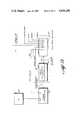
- FIG. 1is a block diagram illustrating an overall system in accordance with the principles of this invention.
- FIG. 2is a block diagram illustrating signal flow in accordance with the present invention.
- FIG. 3is a block diagram illustrating modification of a cable converter in accordance with the present invention.
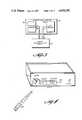
- FIG. 4illustrates the mode switches and data wand of a data collection unit in accordance with the present invention.
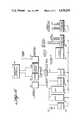
- FIG. 5is a detailed block diagram of a data collection unit in accordance with the present invention.
- FIG. 6is a block diagram of the telephone block interface and master/slave coupling in accordance with one embodiment of the invention.
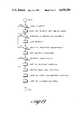
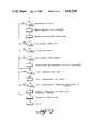
- FIG. 7is a logic flow diagram of the main loop of a data collection unit in accordance with the present invention.
- FIG. 8is another logic flow diagram for converter control in accordance with one embodiment of the present invention.
- FIG. 9is a logic flow diagram of another subroutine in accordance with the present invention.
- FIG. 10is a logic flow diagram for the data LED control subroutine of one embodiment of the present invention.
- FIG. 11is a logic flow diagram of a subroutine also relating to converter control.
- FIG. 12is a logic flow diagram related to storing optically scanned data from a bar code reader in accordance with one embodiment of the present invention.
- FIG. 13is a logic flow diagram relating to control of a time window for telephone communications in accordance with one embodiment of the present invention.
- FIG. 14is a logic flow diagram relating to the survey function of one embodiment of the present invention.
- FIG. 15is a logic flow diagram for a communication subroutine in accordance with one embodiment of the present invention.
- FIG. 16is a block diagram relating to an aspect of the invention in which viewer identification prompts are overlayed on the television screen.
- FIG. 17is a block diagram of an alternate embodiment of the present invention in which a portable data collection device is used to retrieve data from data collection units instead of telephone links.
- the present inventionrelates to a data gathering system which includes a plurality of remote units which are controlled from a central location.
- Each of the remote unitsis attached to a television receiver which is generally but not necessarily attached to a cable system.
- Each of the remote unitsfunctions to determine which of several TV modes is in use as well as to store TV channel selector data and data from an optical input device. All this data is stored for later transmission by each of the remote units to a central data collecting point.
- a video message for a TV viewercan be transmitted from the central location and stored at the remote units, for later display on the TV set associated with the remote units. Further embodiments of the invention allow for substitution of alternate programming information by the central control point on selected of the remote units.
- FIG. 1there is shown a block diagram of the overall system.
- the systemis illustrated in the context of a cable TV system; the invention is not necessarily limited thereto, however.
- signals on normal television channelsare received by head end antennas 11 associated with a CATV head end control system 12.
- the signals from the normal television channelscan be mixed with videotape or film sources from auxiliary sources 13 and 14.
- a control source 16is also provided for transmitting digital data from and under the control of a microcomputer 17. These will be discussed in more detail later.
- FIG. 1illustrates one of the remote units of this system of this invention, although it should be understood that a plurality of such remote units are provided, suitably situated in homes of panelists or the like who have agreed to serve on panels.
- a cable converter 19 and a data collection unit 21 as provided in accordance with the present inventionare both coupled to the cable system 18.
- a normal television receiver 22is coupled to the cable converter 19.
- the data collection unit 21contains a memory, and stores data as to which of a plurality of TV modes are in use, which TV channel is being viewed, as well as input from a suitable optical scanning device, which will be discussed in more detail later.
- other datacan be collected by the data collection unit, such as viewer qualitative rating of programs and responses to survey questionnaires and the like.
- the data collection unit 21is interconnected to a telephone block 22, through which incoming and outgoing telephone calls are coupled to the panelist's home with suitable wiring and the like interconnecting telephone receivers 23 in the panelist's home.
- a central data collection pointis provided for the system in accordance with this invention, which need not be the same central location as the CATV head end 12.
- the central locationis indicated in FIG. 1 by the central computer 24.
- the central locationcan include an appropriate computer with modems and the like for making connection over the switched telephone network 25 to each of the remote locations. This is illustrated in FIG. 1 by the connection between the switched telephone network 25 and the telephone block 22 for the particular remote location shown in FIG. 1.
- the central computer 24"dials-up" each of the remote locations, establishes appropriate telephone communications with each of the data collection units 21, and the data stored in each of the data collection units 21 is transmitted via the switched telephone network 25 to the central computer 24.
- the central computer 24can also download via the telephone lines data into each of the data collection units 21, as discussed in more detail hereafter. Also as discussed in more detail hereafter, in accordance with one aspect and embodiment of the invention, appropriate interconnections are provided in the telephone block 22 so that when a telephone call comes in from the central computer 24, the call is routed to the data collection unit 21, and does not activate the telephone receivers 23 in the panelist's home.
- the data collection unit 21includes an electronics portion 26 and a switching portion 27.
- the switching portion 27consists of a number of switches, five in the embodiment shown in FIG. 2, for selecting which of a variety of TV modes are to be utilized.
- the inputs to the switching portion 27are the normal TV signal from a cable or antenna, along with an interconnection to a computer, i.e. home computer, a VCR, and a game. Depression of one of the five pushbuttons in the switching portion by a viewer or panelist selects one or the other of these TV modes.
- a TV mode signal corresponding to and indicative of one of these TV modesis stored in the data collection unit electronics section 26.
- text informationsuch as survey questionnaires and the like, can be downloaded from a central location over the telephone lines and stored in the data collection unit electronics 26. Selection of a "survey" function by the panelists, actuates this TV mode and video text information is coupled through the corresponding switch in the switching portion 27 and coupled over RF signal line 28 to the input of the cable converter 19.
- the output of the cable converter 19is of course suitably connected to the television receiver 22.
- control informationis coupled both ways between the cable converter 19 and the data collection unit 26.
- the data collection unit electronics 26which controls the television program material displayed on the television receiver 22, rather than the cable converter 19.
- Cable converterstypically include a microprocessor section illustrated in FIG. 3 by reference numeral 29 and a tuning section illustrated in FIG. 3 by reference numeral 31.
- the Teknika 6401 cable converterincludes such an arrangement, and a ribbon cable is normally supplied connecting the microprocessor board 29 to the tuning section 31.
- the microprocessor sectioncontrols a digital display and television receiver commands are received from a front panel on the cable converter, or a remote control as well know in the art.
- the microprocessor sectionsends commands to the tuning section via the ribbon cable normally connecting the two.
- the ribbon cable from the microprocessor board or sectionis interrupted and is connected to the data collection unit 21.
- the commands and the like from the microprocessor section 29are interpreted by the data collection unit 21, which then in turn controls selection of a channel by the tuning section or board 31.
- the data collection unit 21will normally cause the tuning section 31 to select and display whatever channel was indicated in the command information from the microprocessor section 29.
- the data collection unit 21will or can substitute programming, i.e. select a channel for display other than the channel indicated by the commands from the microprocessor board 29, for display at the television receiver.
- the interconnection between the data collection unit 21 and the cable converterenables the data collection unit 21 to store information as to the channel being viewed and at what times, etc.
- FIG. 4there is shown a representation of the physical appearance of the data collection unit 21 in accordance with the present invention.
- the unitis preferably dimensioned such that a cable converter, such as the Teknika 6401 converter will sit right on top of the data collection unit.
- a cable convertersuch as the Teknika 6401 converter will sit right on top of the data collection unit.
- five TV mode selector switchesare provided in the form of pushbutton switches. These correspond to TV, game, computer, VCR, and survey.
- survey questionnaires and the likecan be downloaded from the central location over the telephone lines to memory in the data collection unit.
- a light emitting diode 32is provided on the front panel of the data collection unit in association with the survey pushbutton.
- the light emitting diode 32is lit in a manner discussed hereafter, so as to inform the panelists that there is an unanswered questionnaire.
- An additional data light emitting diode 33is provided on the front panel of the data collection unit and provides further communication with a panelist, as discussed in detail hereafter.
- a receptacle 34provided in the front panel of the data collection unit.
- the receptacle 34is adapted to receive a data wand 35, and an additional light emitting diode 36 is provided on the front panel of the data collection unit for displaying indications relative to the data wand.
- the data wand 35is an optical scanning device which contains its own internal memory.
- the data wand 35can be used for scanning bar codes, such as the UPC codes found on products, and storing information relative to those bar codes.
- the data stored within the data wand 35can be periodically transmitted to memory within the data collection unit, by inserting the data wand 35 into the receptacle 34.
- a suitable example of an optical scanning device 35 for recording bar codesis that manufactured by MSI Corporation and sold under the trademark "DATA WAND.”
- the MSI data wandis available with an RS-232C-type standard interface, which is incorporated into the data collection unit 21 in accordance with the present invention. This interface allows connection to the computer and memory provided in the data collection unit, as discussed more fully hereafter.
- FIG. 5there is shown a functional block diagram of a data collection unit in accordance with the present invention.
- the heart of the data collection unitis a microprocessor 37 and suitable programming for the microprocessor is contained in a ROM 38. Details of the programming are discussed hereafter.
- a RAM 39is also provided for storing event information such as channel selection, TV mode selection, data read by the optical scanner 35 and the like.
- a clock 40is also provided to run the microprocessor 37, with the clock 40 also functioning to maintain a time of day indication for recording times in connection with events in the RAM 39.
- the RAM 39typically is provided with 32k bytes storage. Also typically, 8k bytes of ROM is provided.
- the data collection unitcontains a serial line driver 41, which is appropriately selected to be one of those available which has a programmable baud rate.
- This serial line driver 41is connected via a multiplexer 42 to a variety of interfaces.
- a wand interface 43is provided for accepting data from the optical scanner 35.
- the wand interface provided with the MSI data wandhas a standard RS-232 output at a 1200 baud rate.
- Another input to the multiplexer 42is a modem 44 contained within the data collection unit.
- the modem 44is a Bell 202 compatible, half duplex modem with an auto answer capability. This modem 44 is coupled to the telephone block interface 22, which is described in more detail hereafter.
- the data transfer rate via the modem 44is also 1200 baud.
- the data collection unitalso contains a receive only interface, shown as simplex receiver 45 in FIG. 5 which receives an input from the cable system.
- This simplex channeluses an FM carrier on the cable and originates as a broadcast from the CATV head end.
- certain control informationis transmitted to the remote data collection units via this cable simplex channel.
- the transmission speed of this channelin accordance with one embodiment is 9600 baud.
- a master/slave communication block 46is shown in FIG. 5 as coupled to the telephone block interface 22. This master/slave communication block is only applicable where a plurality of television sets are provided in one panelist's home. The specific functioning of the master/slave relationship is described hereafter in connection with FIG. 6.
- a parallel interface 47is provided for providing the interface between the data collection unit and the cable converter.
- the inputs and outputs of this parallel interfaceare from the microprocessor in the cable converter and to the tuning section of the cable converter (see FIG. 3).
- a parallel interface 48is also provided for decoding the mode or function select switches provided on the front panel of the data collection unit (see FIG. 4) and for controlling the three light emitting diodes 32, 33 and 36 on the front panel of the data collection unit.
- the video interface 49is provided for providing video output information to the television receiver through the cable converter to display survey questionnaires and the like on the television receiver when the survey mode is selected.
- survey questionnairescan be downloaded over the telephone lines from the central location to the remote units while they are in telephone communication.
- the survey questionnairesare stored in RAM 39 and light emitting diode 32 is lit on the front panel of the data collection unit to inform the panelists that there is an unanswered questionnaire.
- the video interface 49produces a composite video signal for display on the television receiver to display the questions in the questionnaire.
- a battery 50is also shown in the functional block diagram of FIG. 5. Although normal power connection for powering the data collection units is via the normal household power supply, a battery backup can be provided to ensure that the data collection unit remains powered up during any temporary power outages at the panelist's home, so as not to lose current time of day information in the clock 40 or any of the data stored in the RAM 39.
- All of the circuitry functionally illustrated in the block diagram of FIG. 5, with the exception of the master slave communications 46 and the telephone block interface 22,can be any appropriate integrated circuits or the like which are available on the market for the functions indicated.
- An important aspect of the data collection unit in accordance with the present inventionis its interface to the cable converter. Specifically, it is the data collection unit itself which controls the tuning of the cable converter. The viewer or panelist appears to control the cable converter normally, but the signals are actually intercepted by the data collection unit and it is the data collection unit that commands the tuning of the converter, as has been described above in connection with FIGS. 2 and 3. During most television viewing activity, the data collection unit will command the tuner to select the same channel that the viewer has selected. However, when in functions which are described as "Channel-Lock" and during "Dynamic Allocation", the data collection unit will select channels other than the one being displayed.
- Channel Lockis a data collection unit function in which the cable converter remains locked on one channel regardless of the activity occurring with the converter control and the channel number being digitally displayed on the cable converter.
- Channel Lockis entered by selecting an unoccupied converter channel, such as channel 35.
- the data collection unitdecodes channel 35, it will freeze the converter on the channel previously selected and illuminate light emitting diode 33 on the front panel of the data collection unit (see FIG. 4). The viewer or panelist can now use the converter control to display any channel number on the converter without changing the channel being viewed.
- the data collection unitwill collect events, as in the normal viewing mode, including storing the subsequent channels selected during the Channel Lock condition as events.
- This Channel Lock featureis useful from a number of standpoints. For example, when in a Channel Lock condition the viewer could select various channels for entry as events with the various channel numbers selected corresponding to the viewers qualitative reaction to programming. As another example, a particular channel number could be entered while in the Channel Lock condition which corresponds to the identification of particular individuals who are viewing the program within the household. A particular embodiment of identifying viewers is described hereafter in connection with FIG. 16. Likewise, selection of channel numbers while in a Channel Lock condition is useful in connection with responding to survey questionnaires and the like, which is described more fully later.
- a key feature of the present inventionis that entry of such qualitative viewer reaction data and the like is achieved while being able to use the normal channel selector associated with the cable converter, rather than any kind of separate key pad or other data entry device.
- the "Channel-Lock" conditionis exited by selecting an unoccupied converter channel, such as 36, at which time the light emitting diode 33 is extinguished and normal tuning of the converter is resumed.
- the select switches or mode switches provided on the front panel of the data collection unitallows the viewer to select one of a number of alternate signal sources.
- these possible alternative signal sourcesare TV (either cable or air), VCR, game, computer and survey.
- the switches as shown in FIG. 2select one of the signal sources and route it to the input of the cable converter.
- the data collection unitmonitors the switch selection and controls the converter tuning accordingly. If TV viewing is selected, then normal converter operation is enabled. If one of the other four sources are selected, the data collection unit will record an event and tune the converter to the appropriate channel to tune the signals which are selected.
- the game and VCR outputmay be on channel 3, while the computer output is on channel 10.
- Dynamic allocationis a term used to describe the concept of blind or invisible channel substitution.
- U.S. Pat. No. 3,639,686 to Walker et alrelates to such a dynamic allocation or substitute programming kind of system.
- a substitute programming arrangement in accordance with the principles of the Walker et al patentis incorporated.
- the dynamic allocation processis one in which one or more channels in selected households are substituted with another test channel by the data collection unit.
- the materials substitutedusually are commercials, for purposes of market research with respect to the efficacy of commercials.
- a set of substitute commercial cut-insare scheduled each day. For example, each cut-in can be assigned a two digit number.
- a channel remap tableis loaded into the data collection unit.
- the remap tablesare simple and consist, for example, of one or more channel numbers and the channel they are to be remapped to.
- the memory in the data collection unitcan hold a number of such remap tables.
- the remap tablesare downloaded over the cable channel and received by the simplex receiver 45 (FIG. 5).
- Each data collection unithas an identification number. There can either be unique identification numbers for each data collection unit corresponding to each panelist location, or panelists can be grouped in accordance with demographic considerations and assigned a common identification number. Identification numbers for each data control unit can be downloaded to the unit from the central location during telephone communications between same.
- the dynamic allocation remap tablesare downloaded over the cable channel and received by the simplex receiver 45 at each of the data collection units. These remap tables are stored in RAM 39.
- a remap tableis enabled, during the cut-in, by continually transmitting the cut-in number down the cable to the simplex communication channel. Whenever a data collection unit receives a cut-in number, the particular remap table is enabled for some predetermined time, i.e. 0.5 seconds.
- the data collection unitautomatically provides substitute programming as indicated by the remap table to the television receiver of the panelist. This alternate programming is transmitted from the cable head and down channels normally not used for entertainment.
- This dynamic allocation featurefacilitates market research. By displaying alternate forms of a commercial to different groups of panelists, and correlating that display both with the demographic data concerning the panelists and the product purchases by the panelists, the efficacy of the commercials can be evaluated.
- the identification of that panelistis scanned into the computer at the store, along with the product purchase information with respect to that panelist.
- This informationis either coupled from the store's computers to the market research organization, or collected at a later time from the stores by the market research organization.
- the data collection unit in accordance with this one aspectis equipped with an optical scanner, one suitable example of which is a product known as the MSI data wand.
- Thisis a hand held device that contains an internal memory and can be used for scanning bar codes, such as universal product codes, contained on products purchased by a panelist.
- product purchase information with respect to a particular panelistis easily collected by the panelist simply scanning the data wand over the universal product codes on the products purchased by the panelist.
- the MSI data wandhas an internal memory which can store approximately 4,000 digits. This memory is of a sufficient extent to store the product code and a price for about 300 items, which should be adequate for recording the daily purchases for a household.
- the data wandcan be inserted into the receptacle in the front panel of the data collection unit and the memory contents of the data wand transferred to memory within the data collection unit.
- the MSI data wandcan be obtained with an RS-232 interface for this purpose, which interface is incorporated within the data collection unit.
- the procedure for transferring the data wand information into the data collection unitis as follows. The panelist turns on the cable converter, enters the channel lock condition, and then selects an unused channel, such as 34, which is programmed to instruct the data collection unit to monitor the interface with the data wand.
- the panelistthen scans the data wand over a special code that is provided with the data wand which instructs the data wand to transmit data.
- the data wandis then inserted into the holder or receptacle within the data collection unit.
- the light emitting diode 36(see FIG. 4) provided on the front panel of the data collection unit will blink off and on for five seconds, so as to inform the panelist that the operation has been successfully completed.
- the panelistextracts the wand from the data collection unit, clears the wand memory in accordance with features provided in the data wand, and reinserts the data wand into the data collection unit for storage in the receptacle.
- a survey questionnaire or the likemay be downloaded over the telephone lines into memory of the data collection unit.
- the data collection unitwill illuminate the survey light emitting diode 32 on the front panel of the data collection unit so as to inform a panelist that the data collection unit contains a survey which has not been answered. Anytime that this light emitting diode 32 is illuminated, the panelist may elect to turn on the television and depress the survey select mode select switch on the front panel of the data collection unit.
- the data collection unitwill detect depression of the survey select switch, illuminate the data light emitting diode 33, tune the cable converter to the appropriate channel, and output the first question to the television through the video interface 49 (FIG. 5).
- the converteris automatically placed in a channel lock condition at this time by the data collection unit.
- the viewercan thus use the converter control or channel selector to enter channel numbers to answer whatever questions are presented in the questionnaire. For example, a questionnaire might ask a question and give five possible responses, with a number beside each of the possible responses. The panelist enters a channel number corresponding to the number adjacent the answer the panelist is giving to the question.
- the data light emitting diode 33 on the front panel of the data collection unitwill be extinguished.
- the survey light emitting diode 32will also be extinguished.
- the transfer of data from the remote data collection units to the central locationis achieved in one embodiment by telephone communications over the switch telephone network between the central location in each of the various remote units.
- FIG. 6there is shown one embodiment of the invention which illustrates the manner of effecting telephone communications from a remote location or panelist's home to the central location, and also the situation in which there is more than one television receiver in a single panelist's home which have to be monitored.
- FIG. 6there is illustrated a telephone block generally indicated by reference numeral 55.
- the telephone blockincludes terminals for the telephone lines 56 and 57 and may also contain several other devices to protect telephone line service, such as lightening arresters and voltage limiters (not shown).
- the telephone blockalso contains a low voltage transformer indicated by reference numeral 58 which is used to supply lighting power to the telephone.
- the telephone lines 56 and 57are respectively green and red and extend to a number of telephone jacks, two of which 59 and 60 are illustrated in FIG. 6.
- Two signal lines 61 and 62 from the low voltage transformer 58also extend to the various telephone jacks and are color coded yellow and black, respectively.
- a telephone block interface 22is provided at the point of the telephone block within a building.
- This telephone block 22is interfaced to the telephone lines 56 and 57 as well as the low voltage power lines 61 and 62.
- Low voltage from the transformer 68is used to supply power via a power supply 63 to a tone detector 64.
- This tone detector 64is a low energy detector used to detect the presence of a control tone, for example a 150 KHz signal which can be imposed on the low voltage lines 61 and 62, in a manner discussed hereafter.
- the tone detector 64is connected to the power lines 61 and 62 via coupling capacitors 65 and 66.
- the tone detector 64is coupled to and controls a relay 67 which is actuated between the position shown in FIG. 6, wherein the telephone lines 56 and 57 are not interrupted, to a position where the telephone lines 56 and 57 are coupled through a load resistor 68 and capacitors 69 and 70.
- FIG. 6there is shown a master data collection unit 71 which is typically connected to a television receiver 72.
- a modem 73which as discussed previously can be a standard kind of modem, such as an auto-answer Bell 202 modem. This is a 1200 baud, half-duplex device.
- the modem 73 in accordance with this inventionis also connected to a telephone jack, for connection to the telephone lines 56 and 57.
- a tone generator-encoder 74is coupled to the master data collection unit 71 and through a resistor 75 to one of the power lines 61 and 62.
- a tone decoder 76is also coupled through a load resistor 77 to one of the signal lines 61 and 62 and through an amplifier 78 to the master data collection unit 71.
- the master data collection unit 71will enable the modem 73 for a limited period of time or "window" each day. Typically, a call-in window of a two hour duration will be opened once per day at a time when the telephone system is normally not in use, i.e. 4-6 a.m. in the morning. During this time window, the master data collection unit 71 will answer each incoming telephone call, and quickly determine if the call originates from the central location. The manner in which this is done is as follows.
- a ring signal occurring at the telephone block 55is a signal of about 45 volts at 25 Hz. This is impressed across the telephone signal lines 56 and 57, and would normally cause telephone sets connected to the telephone service to ring.
- the master data collection unit 71samples the first half cycle of any incoming signal during the call in window for voltage and pulse duration. If the microprocessor within the master data collection unit 71 determines the signal is a ring signal, the tone generator encoder 74 is caused by the data collection unit 71 to impress a 150 KHz tone on the low voltage lines 61 and 62. In response to this tone, the tone detector 64 actuates the relay 67. With the relay 67 actuated, the remainder of the ring signal is absorbed by the load resistor 68. Since load resistor 68 is sufficiently low in value to indicate to the telephone system that a connect has been made, there will be no further rings.
- the modem 73is a standard telephone modem well known to those skilled in the art. This modem is caused by the microprocessor within the master data collection unit 71 to send a two to four second tone, such as a 380 Hz side tone, back to the calling source via the telephone lines 56 and 57 and the coupling capacitors 69 and 70. If the calling source is in fact the computer at the central location, the computer at the central location will respond with an answering tone, and two way computer-to-computer conversation will be established. If, on the other hand, there is no answering tone from the source of the telephone call, indicative that the calling party is not the central location computer, the data collection unit 71 removes the 150 KHz carrier tone on the low voltage leads 61 and 62, causing a disconnect.
- a two to four second tonesuch as a 380 Hz side tone
- the telephone callerwould hear the side tone and the disconnect, and a dial tone would be returned. If such a call comes in and a disconnect occurs, the data collection unit 71 is programmed to disable the tone generator encoder 74 for a predetermined period of time, such as twenty minutes. Thus, any calls coming in during this next predetermined time period of twenty minutes or the like would cause normal telephone ringing. The caller, having been disconnected, would then be able to dial his call again, this time with success. Inasmuch as the sequence of events occurs outside of normal telephone usage hours, it is not believed that such a sequence of events represent any serious impairment to normal telephone usage.
- the central computerupon establishment of that communication the central computer, under appropriate programming, calls on the master data collection unit for the information stored during the day.
- the central locationmay cause a new program to be loaded into the data collection unit 71 memory, such as a questionnaire or the like as discussed previously. If the master data collection unit 71 is the only data collection unit to be communicated with by the central location, the central computer upon completion of receiving the stored information and loading any new program information into the master data collection unit 71 simply disconnects, and all circuits return to normal.
- FIG. 6one embodiment of the invention is also illustrated in which there are multiple television receivers within a single panelist's home which must be monitored.
- two additional television receivers 81 and 83might exist in a panelist's home, and slave data collection units 80 and 82 are associated therewith as illustrated in FIG. 6.
- These slave data collection units 80 and 82are coupled to the low voltage lines 61 and 62.
- the slave data collection unitscan be connected to any of the various telephone jacks within the panelist's house, and coupling to the master data collection unit and the other circuitry is by means of the existing telephone wiring within the household.
- all signals received from the central location via the modem 73are sent first to the master data collection unit 71, then echoed via the tone generator 74 to the signal lines 61 and 62 so that the slave data collection units 80 and 82 receive the incoming data.
- Tone generator 74generates a multiplicity of tones to keep the relay 67 closed, plus an additional variable frequency tone representing the data being transmitted. These tones range, for example, from a 150 KHz to 350 KHz and are impressed as carrier currents on the signal lines 61 and 62.
- Each of the slave data collection unitscontains a microprocessor and would require a tone generator and tone decoder similar to the tone generator 74 and tone decoder 76, but would not require any separate modem.
- Each of the slave data collection unitsreceives the identical data to the master data collection unit 71.
- the slave data collection unitscan be caused to act independently.
- the tone decoder 76receives the signal from the slave data collection unit, decodes it into standard data which is then echoed by the master data collection unit 71 through the modem 73 to the central location.
- each of the data collection unitswhich are coupled together via the existing telephone wiring in a panelist's home, receives all of the incoming information from the central location, and can be caused to respond independently to transmit data stored in each of the data collection units back to the telephone lines to the central location.
- the master data collection unitcan poll each of the slave data collection units by carrier current over the low voltage telephone wiring 61 and 62 to collect the available data at each of the slave data collection units, addressing each of these slave data collection units seriatum by code as necessary.
- a plurality of data collection unitscan be provided within a single panelist's home associated with a respective different plurality of television receivers, for monitoring each of the television receivers in the same fashion as a single data collection unit is provided to monitor one single television receiver.
- the various slave data collection unitshave been shown as coupled to the master data collection unit through the existing telephone wiring in a panelist's home, it should be clear that existing power wiring within a panelist's home can also be used for the same function. That is, carrier signals can be impressed upon the power wiring within a panelist's home for transferring data to and from various slave data collection units to the master data collection unit.
- dedicated wiringcould be installed in a panelist's home for connecting the various slave data collection units to the master data collection unit.
- the first decision blockis as to whether or not there is a cut-in message present. It will be recalled as discussed previously that remap tables for achieving dynamic allocation or substitute programming are stored in the memory of the data collection units and are enabled by transmission of a cut-in number down the cable. If there is a cut-in message present, the cut-in activation event is logged, and all flags in the system are cleared. If there is no cut-in message present, then the logic flow is to the next decision block as to whether or not the channel lock is on. If the channel lock is on, the next decision block is to whether or not a data wand start condition exists.
- the logic flowis jump subroutine (JSR) to data wand read module.
- JSRjump subroutine
- the no conditions to the decision block for the channel lock on and data wand startlead to a decision block as to whether or not connection to central site is established. If it is, the next block is a jump subroutine (JSR) to communication module. If connection to central cite is not established, then the next decision block is to whether or not the clock is advanced to the next second. If it is not advanced to the next second, the logic flow is back to the upper portion of the main loop (ML). If the clock is advanced to the next second, the next decision block is to whether or not the converter is on. If the converter is on, the logic flow progresses to a main loop 1 (ML1).
- JSRjump subroutine
- the next decision blockis to whether or not the converter was on. If it was not, the logic flow is back through the main loop ML. If the converter was on, then the next decision block is to log an off event, and turn off the data light emitting diode (light emitting diode 33 in FIG. 4).
- the timing of the lower portion of the logic flow diagram indicated in FIG. 7 i.e. as to whether the converter is on,is executed once per second in accordance with the programming.
- Other aspects of subroutinessuch as the converter control subroutine discussed hereafter, are interrupt driven and operate asynchronously to the bottom portion of the ML loop in FIG. 7. Components of the data collection unit system which are interrupt driven pass flags and values to this main loop ML for logging and dispatching.
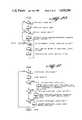
- FIG. 8there is shown the logic flow diagram for the main loop 1 (ML1).
- This loopis entered when the logic flow in FIG. 7 has a yes decision as to whether or not the converter is on.
- the first decision block in the loop ML1is to whether or not the converter was off. If the converter was off, an on event is logged, and the blink flag is set (which was discussed later causes the data light emitting diode to blink). If there is a no decision to the logic block as to whether the converter was off, the logic flow is to the decision block as to whether or not there is a change in the select switches. If there is, an event is logged and the logic flow passes to a decision block as to whether or not a non-TV position is selected.
- the appropriate output channelis set on the converter for whatever position is selected, i.e. computer, VCR, etc.
- the next decision blockis to whether or not the select switches are in the survey position. If so, there is a jump subroutine (JSR) to the survey module. Next, there is a jump subroutine to data LED control, and following that a jump subroutine to test converter channel. Following that, there is a jump subroutine to window control.
- This window controlrefers to whether or not the time window permitting call in from the central location to the remote unit is open or closed. As previously discussed, advantageously a two hour window may be employed at a time when it is not expected that the telephone in the panelist's home will be in use, i.e. early in the morning hours.
- the subroutine illustrated in logic flow diagram form in FIG. 9is interrupt driven with the rate thereof set as a system parameter. In accordance with one embodiment of the invention, the interrupt rate is nominally set for 0.1 second.
- the flags and values set in the subroutine illustrated in FIG. 9are monitored by the main loop illustrated in FIG. 7.
- the first decision blockis to whether or not the converter is on. If the converter is on, the select switches are read and the converter channel is read.
- the next decision blockis as to whether or not the channel lock is on. If the channel lock is not on, the next decision block is whether or not the TV is selected. If the TV is selected, the next decision block is whether or not the channel has been changed. If the channel has been changed, then the subroutine commands the converter to tune to the new channel.
- the bottom portion of the logic flow diagram of FIG. 9relates to clock housekeeping.
- the first decision blockis whether or not there is an increment in the second of day. If there is, the subroutine executes an increment to the seconds of day value.
- the next decision blockis as to whether or not there is a day overflow. If there is, the subroutine resets the second of day and sets a midnight flag, indicative that a day has passed.
- the block labeled RT1is an exit from this subroutine. As indicated, the subroutine is interrupt driven at a rate system parameter, which in accordance with one embodiment is nominally set for 0.1 second.
- FIG. 10there is illustrated a logic flow diagram for the data LED control module, referring to the data light emitting diode provided on the front panel of the data collection unit.
- Thisis the data LED control block illustrated in FIG. 8.
- the first decision blockis as to whether or not the channel lock is on. If it is, the data LED is turned on.
- the next decision blockis as to whether or not the blink flag is set. If it is, the data LED is toggled on and off.
- the next decision blockis whether or not the current time is greater than the blink time. If it is not, there is an exit from the subroutine (RTS). If it is, the blink flag is set if the channel lock is off and the next block time is calculated.
- the subroutinethen loops back to reenter the decision block as to whether or not the current time is greater than the blink time.
- the first decision blockis as to whether or not the channel has changed. If it has, an event is logged.
- Next decision blockis as to whether or not the channel lock is on. If it is, the data LED is turned off (which will appear as a blink when the LED is turned on later) and there is an exit from the subroutine i.e. a return to start. If, on the other hand the channel lock is not on, the next decision block is as to whether or not this is a channel lock entry, i.e. has a channel been selected that corresponds to entering channel lock.
- the channel lockis set on, the data LED is turned on, and the blink flag is turned off and there is a return to start. If, on the other hand, this is not a channel lock entry, the next decision block is as to whether or not the channel entered is a channel lock exit. If it is, the channel lock is cleared and the data LED is turned off. If it is not a channel lock exit, there is a return to start for the subroutine.
- FIG. 12there is shown a logic flow diagram for the data wand read module.
- the first step in the logic flowis to initialize memory pointers, so that the data read in from the data wand is placed in the proper portion of the memory of the data collection unit.
- the next step in the logic flowis to connect the universal asynchronous receiver transmitter to the data wand interface. Characters are then read out one by one from the data wand interface and stored in memory.
- FIG. 13illustrates the logic flow for the window control module. As illustrated, the only decisions are whether or not it is time to open the window or close the window so as to permit establishing telephone communications between the data collection unit and the central location.
- FIG. 14there is shown a logic flow diagram for the survey module the first step in the subroutine is to retrieve the respondent i.d.
- the first step in the subroutineis to retrieve the respondent i.d.
- each of the members of the householdare assigned an i.d. number.
- the survey select switchis selected to enter the survey mode, the channel lock condition of the converter is automatically entered and the converter is tuned to the appropriate channel to display the survey questions.
- the first question presentedis to ask the person answering the survey to enter his or her i.d. number, which is simply a preassigned channel number which the respondent enters.
- the next decision blockis with respect to whether or not there is an exit code in the information coming from the survey data storage in memory. If there is, the subroutine is exited. The next decision block if there is no exit code is as to whether or not there are questions to ask. If there are, various pointers with respect to memory location and the like are initialized and the next question in the survey data is displayed. The respondent responds to the question by entering a channel number that corresponds to one of a plurality of possible answers to the question. This response is retrieved and stored in memory. The next decision block is to whether or not there are any questions remaining for this i.d., i.e. whether or not this particular member of the household has further questions which need to be answered.
- next questionis displayed, the response retrieved and stored, and so on. If there are no questions remaining for this particular respondent, a "questions finished” message is displayed.
- the next decision blockis to whether or not there are questions remaining for any i.d., that is, whether or not there are further survey questions for any other members of the panelist's household. If there are not any further questions remaining for any i.d., the survey light emitting diode is extinguished. As previously discussed, this survey light emitting diode on the front face of the data collection unit is illuminated whenever there are any unanswered survey questions in memory.
- the first step in the subroutineis a fetch command, which is simply a receipt of a character stream.
- the character streamis decoded, and the command dispatch step involves referencing the place in the memory corresponding to the decoded command, and execution of the relevant further commands stored at that location in memory.
- the final decision block in this subroutineis as to whether or not there is a bye command. That is, at the end of the character stream an entry signaling that it is the end of the character stream is inserted, and this decision block decides whether or not the communication is ended.
- Polling the data collection units from a central location using telephone lines and modemsmay not always be the best technique for retrieving stored data from the memories of the data collection units. For example, there are markets where the incidence of private household telephones is small. As another example, there may be some applications in which assembled and analyzed market research data is not needed until a fairly long time interval after the raw data is collected. For these kinds of applications, a different embodiment of the present invention has been developed which uses a portable data collector for collecting data from the data collection unit.
- FIG. 17This alternate embodiment is illustrated in block diagram form in FIG. 17.
- the system as shown in FIG. 17is somewhat similar to the system shown in FIG. 1, and like system components in the two drawings are identified by the same reference numerals.
- the data collection unit 21' shown in FIG. 17can be almost the same data collection unit 21 as referred to previously, with the difference that the modem is eliminated from the data collection unit and an external electrical connector (reference numeral 100 in FIG. 17) is instead provided.
- the telephone block and switched telephone networkare not utilized; that is, there are no telephone connections. Instead of daily transfers of data from the RAM memory of the data collection units to a central computer via telephone, data simply accumulates in the RAM.
- the portable data collectoris simply a digital data recorder including a microprocessor with associated operating ROM and RAM and storage medium, such as magnetic cassette tape or disc.
- the ROMholds all the executable code required to enable the device to communicate with the data collection units and the RAM is used to buffer data extracted from the data collection units.
- Such devicesare commercially available, and one suitable device is available from Pegasus Data Systems of Middlesex, N.J. and identified as Buffered Digital Data Recorder Model PDI-BF. That particular device utilizes a magnetic cassette tape.
- the portable data collectoris simply connected to the external electrical connector 100 of the data collection unit 29'.
- the microprocessor in the portable data collectoris suitably programmed to input the appropriate signals and commands to the data collection unit for transfer of the data stored therein to the portable data collector.
- commandsare simply the same commands as would be given the data collection unit by a central computer over telephone lines in the earlier described embodiment and, for example, would include commands of retrieve data collection unit status, retrieve event data, clear data collection unit data area, reset data collection unit clock (if required), and resume normal data collection unit activity.
- the portable data collection unitis used to play back the recorded data from the data collection units to the central computer 24 as illustrated in FIG. 17.
- the data collection unit serial numberswhich are written onto the tape or disc of the portable data collector along with the data, permit the central computer to identify which particular panelist household corresponds to each block of data recorded in the portable data collection unit.
- the portable data recordermay be a suitable programmed minicomputer or the like, with data extracted from the data collection unit written onto a floppy disc.
- One of the advantageous features of the remote data collection units in accordance with the present inventionis the ability to collect data defining the composition of the television viewing audience in each panelist household.
- one way of achieving this in the present inventionis to use the channel selector to cause the cable converter or tuner to enter a channel-lock condition.
- the data collection unitdisables normal channel tuning so that the channel selector can be used to enter numbers which are stored in the data collection unit memory.
- Each member of the panelist householdis assigned a viewer identification number. These viewer identification numbers are entered into the data collection unit via the channel selector to indicate which members of the panelist household are in the room. While viewers are allowed to enter viewer identification numbers at any time, in an effort to remind viewers to enter the viewer identification numbers, the data collection unit will periodically issue a prompt.
- a viewer identification promptis implemented using the light emitting diode 33 labeled "data".
- the data collection unitsflashes the light emitting diode on and off at a rate of once per second.
- the data collection unitsflashes the light emitting diode on and off at a rate of once per second.
- the data collection unitsflashes the light emitting diode on and off at a rate of once per second.
- theyare expected to enter channel-lock and enter their viewer identifications via the channel selector. Entering channel-lock causes light emitting diode 33 to stop flashing and be illuminated continuously.
- the light emitting diode 33will blink off for half a second to indicate to the viewer that the identification number has been accepted by the data collection unit.
- the channel-lock modeis exited, and light emitting diode 33 is extinguished.
- viewer identification datais obtained in a somewhat different manner.
- the data collection unitincludes hardware and programming which permits presentation of text and graphics on the television receiver to which it is connected. This arrangement can be used to implement the Survey function of the data collection unit.
- a techniqueis implemented to have the viewer identification prompt appear on the television screen itself, no matter what channel is selected.
- a video generator 91is provided which communicates with and reads the contents of a RAM 92 and produces a video output.
- the RAM 92can be part of the RAM 39 illustrated in FIG. 5 and the video generator 91 can be part of the video interface 49 illustrated in FIG. 5.
- the contents of the video data stored in RAM 92are read as lines of 8 bit ASCII characters.
- the output of video generator 91is passed through an RF modulator 93 which is, in effect, a small TV transmitter that sends a picture displaying the characters stored in the RAM 92.
- the carrier frequency for this signalis fixed to be identical to that of the output of the cable converter, which is usually channel 3.
- the cable converterconverts all incoming television signals to a single output channel, for example, channel 3.
- a small receiver 94is used to demodulate this RF signal and extract the vertical sync pulse. This pulse is fed into a synchronizer circuit 96, which starts the RF modulator 93 and video generator 91.
- the RF signal from RF modulator 93is presented to a switch 97.
- the switch 97is a suitable electronic switch for high speed switching of an RF signal. This switch selects the RF signal from either the cable converter or the RF modulator 93 and directs the selected signal to the television receiver.
- Switch 97is controlled by a switch control circuit 98.
- This switch control circuit 98detects the border that appears around the area on the television screen where the text is written.
- the signal level change that occurs at the left edge of a screen of textis a trigger causing the switch control circuit 98 to set the switch 97 to select the output of RF modulator 93.
- the switch control circuitcan also detect the transfer of a byte of data in which all the bits are set (i.e. hexadecimal FF) from the RAM 92 to the video generator 91.
- the detection of a data byte with all bits setcauses the switch control circuit 98 to reset switch 97 to select the converter output.
- the textcan appear anywhere on the television screen. Each line of text is displayed until the end of the line or until a byte containing hexadecimal FF is read from the RAM 92. If a text line is not to be displayed, the byte corresponding to the first character of that line is set to hexadecimal FF. Full lines or portions of lines can be switched. The overall effect is that of lines of characters being displayed over the picture from the cable converter.
- the microprocessorcontrols this display via the RAM 92 and an overlay enable line 99.
- the microprocessorfirst loads RAM 92 with the characters to be displayed and bytes of hexadecimal FF to define areas of the screen that are to remain unaffected.
- the microprocessorsets the overlay enable line 99, the text is displayed over the normal picture.
- the overlayed textis removed when the microprocessor clears the overlay enable line.
- the viewer identification, prompting signaltakes the form of two flashing symbols (such as **) in the upper left portion of the television screen.
- the two symbols (**)appear on the screen and blink continuously back and forth between two colors at a rate of once per second. These symbols continue to flash until a viewer causes the data collection unit to enter the channel-lock mode.
- the symbols stop flashing and the overlay on the television screenis the following:
- Each of the numbers 2 to 18corresponds to a valid viewer identification for a member of the panelist household.
- the purpose of the special identification numbers 71 and 72is explained hereafter.
- the corresponding number in the display shown aboveis inverted in color to indicate to the person entering the data that the data collection unit has accepted that input. Should a number that is already inverted on the display be entered, that number on the display reverts to its normal color. Thus, multiple entries of the same number will cause the number on the display to toggle back and forth between normal color and inverted color. This allows the person entering the data to change a particular viewer identification entry should that be required.
- the special viewer identification numbers 71 and 72are used to indicate the presence of male and female guests, respectively. If a 71 is entered as a viewer identification number, the following three line display appears as an overlay on the television screen:
- the channel selectorincludes a scan up and scan down control ordinarily used to scan television programming.
- this scan controlcan be used to position or move a cursor on the television screen to "jump" among the various categories displayed in response to entry of the special viewer identifications numbers. Entry of a number through the channel selector while the cursor is positioned at one of the categories is an indication of the number of guests in the specified age categories presented in the room.
- entry of the viewer identification number 72produces an overlay on the television screen with corresponding age categories and directed to female guests present in the room.
- the person entering datacan exist from the channel-lock condition and the display overlay is removed from the screen.
- the text overlays on the television screenare presented with the audience composition information displayed as it was defined the previous time that viewer identification data was entered. If the audience has not changed, this can be signified by merely entering and exiting channel-lock. If the audience has changed, the channel selector and scan control can be used to change any entries that are no longer connected.
- the viewer identification promptis first issued when the television set is turned on.
- the viewer identification promptis also presented whenever a 30 minute period passes with no viewer identification data being entered. In this manner, a complete account of audience composition is recorded by the data collection unit on a current basis for the programming being viewed on the television set.
Landscapes
- Engineering & Computer Science (AREA)
- Signal Processing (AREA)
- Business, Economics & Management (AREA)
- Multimedia (AREA)
- Databases & Information Systems (AREA)
- Health & Medical Sciences (AREA)
- General Health & Medical Sciences (AREA)
- Social Psychology (AREA)
- Marketing (AREA)
- Strategic Management (AREA)
- Finance (AREA)
- Accounting & Taxation (AREA)
- Development Economics (AREA)
- Economics (AREA)
- Computer Networks & Wireless Communication (AREA)
- Physics & Mathematics (AREA)
- General Business, Economics & Management (AREA)
- General Physics & Mathematics (AREA)
- Theoretical Computer Science (AREA)
- Game Theory and Decision Science (AREA)
- Entrepreneurship & Innovation (AREA)
- Computer Graphics (AREA)
- Tourism & Hospitality (AREA)
- Primary Health Care (AREA)
- Human Resources & Organizations (AREA)
- Testing, Inspecting, Measuring Of Stereoscopic Televisions And Televisions (AREA)
- Peptides Or Proteins (AREA)
- Selective Calling Equipment (AREA)
- Two-Way Televisions, Distribution Of Moving Picture Or The Like (AREA)
- Aerials With Secondary Devices (AREA)
- Optical Radar Systems And Details Thereof (AREA)
- Radar Systems Or Details Thereof (AREA)
- Alarm Systems (AREA)
- Analysing Materials By The Use Of Radiation (AREA)
- Telephonic Communication Services (AREA)
Abstract
Description
______________________________________ ** 2 4 6 8 10 12 14 16 18 71 72 PRESENCE OF GUEST ML FM ______________________________________
______________________________________ ML GUEST COUNT BY AGE 2-6: 7-11: 12-17: 18-24: 25-34: 35-49: 50-54: 554: ______________________________________
Claims (11)
Priority Applications (16)
| Application Number | Priority Date | Filing Date | Title |
|---|---|---|---|
| US06/658,378US4658290A (en) | 1983-12-08 | 1984-10-05 | Television and market research data collection system and method |
| EP84114542AEP0144085B1 (en) | 1983-12-08 | 1984-11-30 | Television and market research data collection system and method |
| DE3486466TDE3486466T2 (en) | 1983-12-08 | 1984-11-30 | Data collection system and method for television and market research |
| DE8484114542TDE3484979D1 (en) | 1983-12-08 | 1984-11-30 | DATA COLLECTION SYSTEM AND METHOD FOR TELEVISION AND MARKET RESEARCH. |
| EP90120554AEP0421482B1 (en) | 1983-12-08 | 1984-11-30 | Television and market research data collection system and method |
| AT84114542TATE66769T1 (en) | 1983-12-08 | 1984-11-30 | DATA COLLECTION SYSTEM AND PROCEDURES FOR TELEVISION AND MARKET RESEARCH. |
| AU36049/84AAU563660B2 (en) | 1983-12-08 | 1984-11-30 | Audience surveying system |
| AT90120554TATE166508T1 (en) | 1983-12-08 | 1984-11-30 | DATA COLLECTION SYSTEM AND METHOD FOR TELEVISION AND MARKET RESEARCH |
| MX203637AMX156567A (en) | 1983-12-08 | 1984-12-07 | IMPROVEMENTS IN THE SUPERVISION SYSTEM TO TRANSMIT COLLECTION DATA TO A CENTRAL LOCATION |
| CA000469571ACA1227561A (en) | 1983-12-08 | 1984-12-07 | Television and market research data collection system and method |
| BR8406285ABR8406285A (en) | 1983-12-08 | 1984-12-07 | SYSTEM FOR DATA COLLECTION WITH RESPECT TO COOPERATED OR USER TELEVISION EXPECTATORS AND DATA COLLECTION PROCESS FOR A PLURALITY OF COOPERATED USERS IN A PLATALITY OF REMOTE LOCATIONS |
| ES538355AES8800475A1 (en) | 1983-12-08 | 1984-12-07 | Television and market research data collection system and method. |
| KR1019840007778AKR930004821B1 (en) | 1983-12-08 | 1984-12-08 | Data collection device and data collection method |
| CA000544156ACA1241736A (en) | 1983-12-08 | 1987-08-10 | Television and market research data collection system and method |
| CA000544155ACA1241735A (en) | 1983-12-08 | 1987-08-10 | Television and market research data collection system and method |
| CA000544157ACA1241737A (en) | 1983-12-08 | 1987-08-10 | Television and market research data collection system and method |
Applications Claiming Priority (2)
| Application Number | Priority Date | Filing Date | Title |
|---|---|---|---|
| US06/559,459US4546382A (en) | 1983-06-09 | 1983-12-08 | Television and market research data collection system and method |
| US06/658,378US4658290A (en) | 1983-12-08 | 1984-10-05 | Television and market research data collection system and method |
Related Parent Applications (1)
| Application Number | Title | Priority Date | Filing Date |
|---|---|---|---|
| US06/559,459Continuation-In-PartUS4546382A (en) | 1983-06-09 | 1983-12-08 | Television and market research data collection system and method |
Related Child Applications (1)
| Application Number | Title | Priority Date | Filing Date |
|---|---|---|---|
| US07/036,861ContinuationUS4816904A (en) | 1983-06-09 | 1987-04-10 | Television and market research data collection system and method |
Publications (1)
| Publication Number | Publication Date |
|---|---|
| US4658290Atrue US4658290A (en) | 1987-04-14 |
Family
ID=27072068
Family Applications (1)
| Application Number | Title | Priority Date | Filing Date |
|---|---|---|---|
| US06/658,378Expired - LifetimeUS4658290A (en) | 1983-12-08 | 1984-10-05 | Television and market research data collection system and method |
Country Status (10)
| Country | Link |
|---|---|
| US (1) | US4658290A (en) |
| EP (1) | EP0144085B1 (en) |
| KR (1) | KR930004821B1 (en) |
| AT (1) | ATE166508T1 (en) |
| AU (1) | AU563660B2 (en) |
| BR (1) | BR8406285A (en) |
| CA (1) | CA1227561A (en) |
| DE (2) | DE3486466T2 (en) |
| ES (1) | ES8800475A1 (en) |
| MX (1) | MX156567A (en) |
Cited By (135)
| Publication number | Priority date | Publication date | Assignee | Title |
|---|---|---|---|---|
| US4750034A (en)* | 1987-01-21 | 1988-06-07 | Cloeck En Moedigh Bioscoopreclame B.V. | Apparatus for monitoring the replay of audio/video information carriers |
| US4779198A (en)* | 1986-08-26 | 1988-10-18 | Control Data Corporation | Audience monitoring system |
| US4816904A (en)* | 1983-06-09 | 1989-03-28 | Control Data Corporation | Television and market research data collection system and method |
| US4829558A (en)* | 1988-01-19 | 1989-05-09 | Peac Media Research, Inc. | System and device for data transmission, and related method |
| US4870579A (en)* | 1987-10-01 | 1989-09-26 | Neonics, Inc. | System and method of predicting subjective reactions |
| US4876736A (en)* | 1987-09-23 | 1989-10-24 | A. C. Nielsen Company | Method and apparatus for determining channel reception of a receiver |
| US4885632A (en)* | 1988-02-29 | 1989-12-05 | Agb Television Research | System and methods for monitoring TV viewing system including a VCR and/or a cable converter |
| AU592209B2 (en)* | 1986-08-26 | 1990-01-04 | Control Data Corporation | Method of and apparatus for monitoring a population in a room and for collecting data from television viewers |
| US4905080A (en)* | 1986-08-01 | 1990-02-27 | Video Research Ltd. | Apparatus for collecting television channel data and market research data |
| US4907079A (en)* | 1987-09-28 | 1990-03-06 | Teleview Rating Corporation, Inc. | System for monitoring and control of home entertainment electronic devices |
| WO1990002453A1 (en)* | 1988-08-24 | 1990-03-08 | Sebastiano Scarampi | Apparatus and method for monitoring television viewers |
| US4912552A (en)* | 1988-04-19 | 1990-03-27 | Control Data Corporation | Distributed monitoring system |
| EP0363847A1 (en)* | 1988-10-11 | 1990-04-18 | A.C. Nielsen Company | System for substituting stored video information for another video information |
| US4930011A (en)* | 1988-08-02 | 1990-05-29 | A. C. Nielsen Company | Method and apparatus for identifying individual members of a marketing and viewing audience |
| US4931865A (en)* | 1988-08-24 | 1990-06-05 | Sebastiano Scarampi | Apparatus and methods for monitoring television viewers |
| US4943963A (en)* | 1988-01-19 | 1990-07-24 | A. C. Nielsen Company | Data collection and transmission system with real time clock |
| US4954699A (en)* | 1988-04-13 | 1990-09-04 | Npd Research, Inc. | Self-administered survey questionnaire and method |
| US4974085A (en)* | 1989-05-02 | 1990-11-27 | Bases Burke Institute, Inc. | Television signal substitution |
| US4994908A (en)* | 1988-12-23 | 1991-02-19 | Scientific-Atlanta, Inc. | Interactive room status/time information system |
| US5023901A (en)* | 1988-08-22 | 1991-06-11 | Vorec Corporation | Surveillance system having a voice verification unit |
| US5041972A (en)* | 1988-04-15 | 1991-08-20 | Frost W Alan | Method of measuring and evaluating consumer response for the development of consumer products |
| WO1992017027A1 (en)* | 1991-03-19 | 1992-10-01 | Scientific-Atlanta, Inc. | Apparatus for generating and collecting viewing statistics |
| US5245533A (en)* | 1990-12-18 | 1993-09-14 | A. C. Nielsen Company | Marketing research method and system for management of manufacturer's discount coupon offers |
| US5315093A (en)* | 1992-02-05 | 1994-05-24 | A. C. Nielsen Company | Market research method and system for collecting retail store market research data |
| WO1995004430A1 (en)* | 1993-08-02 | 1995-02-09 | The Arbitron Company | Compliance incentives for audience monitoring/recording devices |
| US5495283A (en)* | 1993-09-13 | 1996-02-27 | Albrit Technologies Ltd. | Cable television video messaging system and headend facility incorporating same |
| US5497185A (en)* | 1991-04-25 | 1996-03-05 | Le Groupe Videotron Ltee. | Remote control system for television audience data gathering |
| WO1996034349A1 (en)* | 1995-04-24 | 1996-10-31 | Bell Communications Research, Inc. | An improved periodic wireless data broadcast |
| US5579057A (en)* | 1993-06-07 | 1996-11-26 | Scientific-Atlanta, Inc. | Display system for selectively overlaying symbols and graphics onto a video signal |
| US5581800A (en)* | 1991-09-30 | 1996-12-03 | The Arbitron Company | Method and apparatus for automatically identifying a program including a sound signal |
| US5675510A (en)* | 1995-06-07 | 1997-10-07 | Pc Meter L.P. | Computer use meter and analyzer |
| WO1998006218A1 (en)* | 1996-08-07 | 1998-02-12 | Information Resources, Inc. | Television distribution system for signal substitution |
| US5740035A (en)* | 1991-07-23 | 1998-04-14 | Control Data Corporation | Self-administered survey systems, methods and devices |
| US5794210A (en)* | 1995-12-11 | 1998-08-11 | Cybergold, Inc. | Attention brokerage |
| US5842199A (en)* | 1996-10-18 | 1998-11-24 | Regents Of The University Of Minnesota | System, method and article of manufacture for using receiver operating curves to evaluate predictive utility |
| US5870724A (en)* | 1989-12-08 | 1999-02-09 | Online Resources & Communications Corporation | Targeting advertising in a home retail banking delivery service |
| US5887243A (en) | 1981-11-03 | 1999-03-23 | Personalized Media Communications, L.L.C. | Signal processing apparatus and methods |
| US5970467A (en)* | 1997-07-31 | 1999-10-19 | Enviro Ec Ag | Accurate market survey collection method |
| US6016475A (en)* | 1996-10-08 | 2000-01-18 | The Regents Of The University Of Minnesota | System, method, and article of manufacture for generating implicit ratings based on receiver operating curves |
| US6020913A (en)* | 1997-04-29 | 2000-02-01 | Trilithic, Inc. | Emergency alert system signal handling method and apparatus |
| US6041311A (en)* | 1995-06-30 | 2000-03-21 | Microsoft Corporation | Method and apparatus for item recommendation using automated collaborative filtering |
| US6092049A (en)* | 1995-06-30 | 2000-07-18 | Microsoft Corporation | Method and apparatus for efficiently recommending items using automated collaborative filtering and feature-guided automated collaborative filtering |
| US6108493A (en)* | 1996-10-08 | 2000-08-22 | Regents Of The University Of Minnesota | System, method, and article of manufacture for utilizing implicit ratings in collaborative filters |
| US6166728A (en)* | 1992-12-02 | 2000-12-26 | Scientific-Atlanta, Inc. | Display system with programmable display parameters |
| US6286140B1 (en)* | 1997-11-20 | 2001-09-04 | Thomas P. Ivanyi | System and method for measuring and storing information pertaining to television viewer or user behavior |
| US6321208B1 (en) | 1995-04-19 | 2001-11-20 | Brightstreet.Com, Inc. | Method and system for electronic distribution of product redemption coupons |
| US20020042923A1 (en)* | 1992-12-09 | 2002-04-11 | Asmussen Michael L. | Video and digital multimedia aggregator content suggestion engine |
| US20020161779A1 (en)* | 2000-03-07 | 2002-10-31 | Brierley Harold M. | Method and system for evaluating, reporting, and improving on-line promotion effectiveness |
| FR2828604A1 (en)* | 2001-08-13 | 2003-02-14 | Scm Microsystems Gmbh | Television programme audience measurement has audience digital word transmission to processing center and viewer presence verification using visual warning/spectator confirmation system |
| US6530082B1 (en) | 1998-04-30 | 2003-03-04 | Wink Communications, Inc. | Configurable monitoring of program viewership and usage of interactive applications |
| US20030196206A1 (en)* | 2002-04-15 | 2003-10-16 | Shusman Chad W. | Method and apparatus for internet-based interactive programming |
| US20030204776A1 (en)* | 2002-04-29 | 2003-10-30 | Testin William John | Eeprom enable |
| US20030204857A1 (en)* | 2002-04-29 | 2003-10-30 | Dinwiddie Aaron Hal | Pre-power -failure storage of television parameters in nonvolatile memory |
| US6647548B1 (en)* | 1996-09-06 | 2003-11-11 | Nielsen Media Research, Inc. | Coded/non-coded program audience measurement system |
| US20040031045A1 (en)* | 1997-11-20 | 2004-02-12 | Ivanyi Thomas P. | System and method for measuring and storing information pertaining to television viewer or user behavior |
| US20040032486A1 (en)* | 2002-08-16 | 2004-02-19 | Shusman Chad W. | Method and apparatus for interactive programming using captioning |
| US20040078292A1 (en)* | 1996-09-03 | 2004-04-22 | Trevor Blumenau | Content Display Monitoring by a Processing System |
| US20040111742A1 (en)* | 1992-12-09 | 2004-06-10 | Hendricks John S. | Method and apparatus for switching targeted advertisements at a set top terminal |
| US20040187167A1 (en)* | 1996-09-16 | 2004-09-23 | Discoverwhy Inc. | Data correlation and analysis tool |
| US6847373B1 (en) | 1999-04-16 | 2005-01-25 | Avid Technology, Inc. | Natural color matching in a video editing system |
| US20050038706A1 (en)* | 2003-08-15 | 2005-02-17 | Amir Yazdani | Business transaction reporting system |
| US20050038914A1 (en)* | 2001-05-17 | 2005-02-17 | Andrew Prendergast | Method of optimising content presented to a user within a communication network |
| US20050114511A1 (en)* | 1997-03-21 | 2005-05-26 | Owen Davis | Method and apparatus for tracking client interaction with a network resource |
| US20060122877A1 (en)* | 2003-08-15 | 2006-06-08 | Amir Yazdani | Systems and methods for measuring consumption of entertainment commodities |
| US20070074258A1 (en)* | 2005-09-20 | 2007-03-29 | Sbc Knowledge Ventures L.P. | Data collection and analysis for internet protocol television subscriber activity |
| US20070083882A1 (en)* | 2004-04-26 | 2007-04-12 | Nielsen Christen V | Methods and apparatus to export tuning data collected in a receiving device |
| US20070119969A1 (en)* | 2003-05-20 | 2007-05-31 | Optimyst Systems Inc. | Ophthalmic fluid reservoir assembly for use with an ophthalmic fluid delivery device |
| US7240022B1 (en) | 1998-05-19 | 2007-07-03 | Mypoints.Com Inc. | Demographic information gathering and incentive award system and method |
| US20070185986A1 (en)* | 2003-01-31 | 2007-08-09 | John Griffin | Method and system of measuring and recording user data in a communications network |
| US20070198327A1 (en)* | 2003-08-15 | 2007-08-23 | Amir Yazdani | Systems and methods for measuring, targeting, verifying, and reporting advertising impressions |
| US20070206606A1 (en)* | 2006-03-01 | 2007-09-06 | Coleman Research, Inc. | Method and apparatus for collecting survey data via the internet |
| US20070263669A1 (en)* | 2006-04-05 | 2007-11-15 | Trilithic, Inc. | Networkable decoder |
| US20080091762A1 (en)* | 2006-07-12 | 2008-04-17 | Neuhauser Alan R | Methods and systems for compliance confirmation and incentives |
| US7376722B1 (en) | 1999-08-06 | 2008-05-20 | Red Sheriff Limited | Network resource monitoring and measurement system and method |
| US20080126420A1 (en)* | 2006-03-27 | 2008-05-29 | Wright David H | Methods and systems to meter media content presented on a wireless communication device |
| US20080155633A1 (en)* | 2000-11-03 | 2008-06-26 | The Walt Disney Company | System and Method For Enhanced Broadcasting and Interactive Television |
| US7401032B1 (en) | 1995-07-25 | 2008-07-15 | News America Marketing Properties | Process for the distribution and redemption of coupons |
| US7406516B2 (en) | 1997-03-21 | 2008-07-29 | Netratings, Inc. | System and method for monitoring the use of a resource by a client connected to a computer network having one or more servers in communication with one or more clients |
| US20080300965A1 (en)* | 2007-05-31 | 2008-12-04 | Peter Campbell Doe | Methods and apparatus to model set-top box data |
| US20090149829A1 (en)* | 2003-05-20 | 2009-06-11 | Collins Jr James F | Ophthalmic fluid delivery system |
| US20090171767A1 (en)* | 2007-06-29 | 2009-07-02 | Arbitron, Inc. | Resource efficient research data gathering using portable monitoring devices |
| US20090212133A1 (en)* | 2008-01-25 | 2009-08-27 | Collins Jr James F | Ophthalmic fluid delivery device and method of operation |
| US20090290756A1 (en)* | 2002-12-11 | 2009-11-26 | Arun Ramaswamy | Methods and apparatus for detecting a composition of an audience of an information presenting device |
| US20090305680A1 (en)* | 2008-04-03 | 2009-12-10 | Swift Roderick D | Methods and apparatus to monitor mobile devices |
| US20100079597A1 (en)* | 2008-09-29 | 2010-04-01 | Robert Joel Stokes | Methods and Apparatus for Determining the Operating State of Audio-Video Devices |
| US20100180296A1 (en)* | 2000-06-19 | 2010-07-15 | Comcast Ip Holdings I, Llc | Method and Apparatus for Targeting of Interactive Virtual Objects |
| US7770196B1 (en) | 1992-12-09 | 2010-08-03 | Comcast Ip Holdings I, Llc | Set top terminal for organizing program options available in television delivery system |
| US7769344B1 (en) | 1981-11-03 | 2010-08-03 | Personalized Media Communications, Llc | Signal processing apparatus and methods |
| US20100195865A1 (en)* | 2008-08-08 | 2010-08-05 | Luff Robert A | Methods and apparatus to count persons in a monitored environment |
| US7827574B1 (en)* | 1993-12-02 | 2010-11-02 | Comcast Ip Holdings I, Llc | Method and apparatus for targeted advertising |
| US20100313215A1 (en)* | 2001-08-03 | 2010-12-09 | Comcast Ip Holdings I, Llc | Video and digital multimedia aggregator |
| USRE42103E1 (en) | 1995-10-30 | 2011-02-01 | Disney Enterprises, Inc. | Apparatus and method of automatically accessing on-line services in response to broadcast of on-line addresses |
| US20110085080A1 (en)* | 2001-08-03 | 2011-04-14 | Comcast Ip Holdings I, Llc | Video and digital multimedia aggregator content coding and formatting |
| US20110093878A1 (en)* | 2009-10-16 | 2011-04-21 | Falcon Fernando D | Audience measurement systems, methods and apparatus |
| US20110138010A1 (en)* | 2009-12-04 | 2011-06-09 | Sling Media, Inc. | Generation of data concerning reception of media content at a communication device |
| US20110213710A1 (en)* | 2008-02-05 | 2011-09-01 | Bank Of America Corporation | Identification of customers and use of virtual accounts |
| US8092307B2 (en) | 1996-11-14 | 2012-01-10 | Bally Gaming International, Inc. | Network gaming system |
| US8190513B2 (en) | 1996-06-05 | 2012-05-29 | Fraud Control Systems.Com Corporation | Method of billing a purchase made over a computer network |
| US8229844B2 (en) | 1996-06-05 | 2012-07-24 | Fraud Control Systems.Com Corporation | Method of billing a purchase made over a computer network |
| US8271778B1 (en) | 2002-07-24 | 2012-09-18 | The Nielsen Company (Us), Llc | System and method for monitoring secure data on a network |
| US8473342B1 (en) | 2000-04-05 | 2013-06-25 | Catalina Marketing Corporation | Method and system for generating certificates having unique Id data |
| US8626581B2 (en) | 1995-06-16 | 2014-01-07 | Catalina Marketing Corporation | Virtual couponing method and apparatus for use with consumer kiosk |
| US8630942B2 (en) | 1996-06-05 | 2014-01-14 | Fraud Control Systems.Com Corporation | Method of billing a purchase made over a computer network |
| US8661111B1 (en) | 2000-01-12 | 2014-02-25 | The Nielsen Company (Us), Llc | System and method for estimating prevalence of digital content on the world-wide-web |
| US8677385B2 (en) | 2010-09-21 | 2014-03-18 | The Nielsen Company (Us), Llc | Methods, apparatus, and systems to collect audience measurement data |
| US8684980B2 (en) | 2010-07-15 | 2014-04-01 | Corinthian Ophthalmic, Inc. | Drop generating device |
| US8733935B2 (en) | 2010-07-15 | 2014-05-27 | Corinthian Ophthalmic, Inc. | Method and system for performing remote treatment and monitoring |
| US8775245B2 (en) | 2010-02-11 | 2014-07-08 | News America Marketing Properties, Llc | Secure coupon distribution |
| US9087145B2 (en) | 2010-07-15 | 2015-07-21 | Eyenovia, Inc. | Ophthalmic drug delivery |
| US9185435B2 (en) | 2013-06-25 | 2015-11-10 | The Nielsen Company (Us), Llc | Methods and apparatus to characterize households with media meter data |
| US9277265B2 (en) | 2014-02-11 | 2016-03-01 | The Nielsen Company (Us), Llc | Methods and apparatus to calculate video-on-demand and dynamically inserted advertisement viewing probability |
| US9332363B2 (en) | 2011-12-30 | 2016-05-03 | The Nielsen Company (Us), Llc | System and method for determining meter presence utilizing ambient fingerprints |
| US9692535B2 (en) | 2012-02-20 | 2017-06-27 | The Nielsen Company (Us), Llc | Methods and apparatus for automatic TV on/off detection |
| US20170255943A1 (en)* | 2015-05-22 | 2017-09-07 | Paypal, Inc. | Hosted sensitive data form fields for compliance with security standards |
| US9838754B2 (en) | 2015-09-01 | 2017-12-05 | The Nielsen Company (Us), Llc | On-site measurement of over the top media |
| US9848224B2 (en) | 2015-08-27 | 2017-12-19 | The Nielsen Company(Us), Llc | Methods and apparatus to estimate demographics of a household |
| US10045082B2 (en) | 2015-07-02 | 2018-08-07 | The Nielsen Company (Us), Llc | Methods and apparatus to correct errors in audience measurements for media accessed using over-the-top devices |
| US10154923B2 (en) | 2010-07-15 | 2018-12-18 | Eyenovia, Inc. | Drop generating device |
| US10169781B1 (en) | 2007-03-07 | 2019-01-01 | The Nielsen Company (Us), Llc | Method and system for generating information about portable device advertising |
| US10219039B2 (en) | 2015-03-09 | 2019-02-26 | The Nielsen Company (Us), Llc | Methods and apparatus to assign viewers to media meter data |
| US10361802B1 (en) | 1999-02-01 | 2019-07-23 | Blanding Hovenweep, Llc | Adaptive pattern recognition based control system and method |
| US10380633B2 (en) | 2015-07-02 | 2019-08-13 | The Nielsen Company (Us), Llc | Methods and apparatus to generate corrected online audience measurement data |
| USRE47642E1 (en) | 1981-11-03 | 2019-10-08 | Personalized Media Communications LLC | Signal processing apparatus and methods |
| US10639194B2 (en) | 2011-12-12 | 2020-05-05 | Eyenovia, Inc. | High modulus polymeric ejector mechanism, ejector device, and methods of use |
| US10791355B2 (en) | 2016-12-20 | 2020-09-29 | The Nielsen Company (Us), Llc | Methods and apparatus to determine probabilistic media viewing metrics |
| US10803475B2 (en) | 2014-03-13 | 2020-10-13 | The Nielsen Company (Us), Llc | Methods and apparatus to compensate for server-generated errors in database proprietor impression data due to misattribution and/or non-coverage |
| US10856031B2 (en) | 2003-04-15 | 2020-12-01 | MedialP, Inc. | Method and apparatus for generating interactive programming in a communication network |
| US11711638B2 (en) | 2020-06-29 | 2023-07-25 | The Nielsen Company (Us), Llc | Audience monitoring systems and related methods |
| US11758223B2 (en) | 2021-12-23 | 2023-09-12 | The Nielsen Company (Us), Llc | Apparatus, systems, and methods for user presence detection for audience monitoring |
| US11860704B2 (en) | 2021-08-16 | 2024-01-02 | The Nielsen Company (Us), Llc | Methods and apparatus to determine user presence |
| US11938056B2 (en) | 2017-06-10 | 2024-03-26 | Eyenovia, Inc. | Methods and devices for handling a fluid and delivering the fluid to the eye |
| US11983730B2 (en) | 2014-12-31 | 2024-05-14 | The Nielsen Company (Us), Llc | Methods and apparatus to correct for deterioration of a demographic model to associate demographic information with media impression information |
| US12088882B2 (en) | 2022-08-26 | 2024-09-10 | The Nielsen Company (Us), Llc | Systems, apparatus, and related methods to estimate audience exposure based on engagement level |
| US12161585B2 (en) | 2019-12-11 | 2024-12-10 | Eyenovia, Inc. | Systems and devices for delivering fluids to the eye and methods of use |
| US12356286B2 (en) | 2021-07-22 | 2025-07-08 | The Nielsen Company (Us), Llc | Methods, apparatus, and articles of manufacture to locate persons based on adjustable signal strength thresholds |
Families Citing this family (18)
| Publication number | Priority date | Publication date | Assignee | Title |
|---|---|---|---|---|
| GB8314468D0 (en)* | 1983-05-25 | 1983-06-29 | Agb Research Plc | Television monitoring |
| US4630108A (en)* | 1984-03-26 | 1986-12-16 | A. C. Nielsen Company | Preprogrammed over-the-air marketing research system |
| US4633302A (en)* | 1985-10-01 | 1986-12-30 | Control Data Corporation | Video cassette recorder adapter |
| GB8613555D0 (en)* | 1986-06-04 | 1986-07-09 | Reilly Mp O | Display apparatus |
| US4872113A (en)* | 1987-08-27 | 1989-10-03 | Jbs Associates, Inc. | Credit check scanner data analysis system |
| US4845741A (en)* | 1988-04-27 | 1989-07-04 | Control Data Corporation | Modem ringing supression circuit |
| GB8900172D0 (en)* | 1989-01-05 | 1989-03-01 | Agb Research Plc | Market research systems and equipment |
| FR2653578B1 (en)* | 1989-10-24 | 1992-01-17 | Adventure | ELECTRONIC PORTABLE DEVICE FOR LOYALIZING A PUBLIC TO A MEDIA OR THE LIKE. |
| CA2041210C (en)* | 1991-04-25 | 1998-12-29 | Michel Dufresne | Television audience data gathering |
| GB2280977B (en)* | 1991-04-25 | 1995-07-05 | Videotron Groupe Ltee | A remote control system for at least selecting television channels |
| US5401946A (en)* | 1991-07-22 | 1995-03-28 | Weinblatt; Lee S. | Technique for correlating purchasing behavior of a consumer to advertisements |
| GB9226427D0 (en)* | 1992-12-18 | 1993-02-10 | Minimetrics Ltd | Market research data logging device |
| AU1195395A (en)* | 1993-12-08 | 1995-06-27 | Michael Jeremy Kew | A communications system and associated apparatus |
| DE19523515C2 (en)* | 1995-06-30 | 1998-01-29 | Bci Rundfunkberatung Gmbh & Co | Process and system for the transmitter-related recording of listener-side data |
| IT1285517B1 (en)* | 1996-09-30 | 1998-06-08 | Nicola Piepoli | TELEMATIC SYSTEM FOR PUBLIC MARKETING OPINION SEARCHES AND SIMILAR |
| NL1010108C2 (en)* | 1997-09-30 | 2003-12-23 | Sony Electronics Inc | Method and device for automatically loading and storing Internet Web pages and for transferring statistical consumer information and data from a network structure. |
| US20110313849A1 (en)* | 2010-06-18 | 2011-12-22 | Klaus Brueck | Method and system for effective market research |
| EP2854407A1 (en)* | 2013-09-30 | 2015-04-01 | Advanced Digital Broadcast S.A. | Method and system for conducting an interactive survey in a cable television network |
Citations (26)
| Publication number | Priority date | Publication date | Assignee | Title |
|---|---|---|---|---|
| US3803349A (en)* | 1971-10-19 | 1974-04-09 | Video Res Ltd | Television audience measurement system |
| DE2404074A1 (en)* | 1974-01-29 | 1975-08-07 | Inst Angewandte Sozialwissensc | PROCEDURE FOR CAPTURING, TRANSFERRING AND PROCESSING TECHNICAL INFORMATION ABOUT THE TELEVISION SWITCH-ON BEHAVIOR OF TELEVISION USERS |
| US3987397A (en)* | 1975-04-25 | 1976-10-19 | Belcher Brian E | Remote unit for a two-way cable communications system |
| US4019174A (en)* | 1971-12-08 | 1977-04-19 | Monarch Marking Systems, Inc. | Data collecting and transmitting system |
| GB1536414A (en)* | 1974-12-11 | 1978-12-20 | Kaldor A | Television audience survey systems |
| US4163254A (en)* | 1977-02-14 | 1979-07-31 | Block Robert S | Method and system for subscription television billing and access |
| US4258386A (en)* | 1978-07-31 | 1981-03-24 | Cheung Shiu H | Television audience measuring system |
| US4264925A (en)* | 1979-08-13 | 1981-04-28 | Michael J. Freeman | Interactive cable television system |
| US4331973A (en)* | 1980-10-21 | 1982-05-25 | Iri, Inc. | Panelist response scanning system |
| US4331974A (en)* | 1980-10-21 | 1982-05-25 | Iri, Inc. | Cable television with controlled signal substitution |
| US4338601A (en)* | 1979-06-28 | 1982-07-06 | Nance Kivell S | Apparatus for the storage and transfer of information |
| JPS57113673A (en)* | 1980-12-30 | 1982-07-15 | Fujitsu Ltd | Questionnaire investigating system by digital signal transmission |
| US4355372A (en)* | 1980-12-24 | 1982-10-19 | Npd Research Inc. | Market survey data collection method |
| US4361851A (en)* | 1980-01-04 | 1982-11-30 | Asip William F | System for remote monitoring and data transmission over non-dedicated telephone lines |
| US4388644A (en)* | 1976-10-18 | 1983-06-14 | E-Systems, Inc. | Apparatus for monitoring a multichannel receiver |
| US4394540A (en)* | 1981-05-18 | 1983-07-19 | Timex Corporation | Remote meter reader and method for reading meters over non-dedicated telephone lines |
| US4404589A (en)* | 1980-10-21 | 1983-09-13 | Iri, Inc. | Cable television with multi-event signal substitution |
| US4503288A (en)* | 1981-08-31 | 1985-03-05 | Novation, Inc. | Intelligent telephone |
| US4536791A (en)* | 1980-03-31 | 1985-08-20 | Tocom, Inc. | Addressable cable television control system with video format data transmission |
| US4546382A (en)* | 1983-06-09 | 1985-10-08 | Ctba Associates | Television and market research data collection system and method |
| WO1985004543A1 (en)* | 1984-03-26 | 1985-10-10 | A.C. Nielsen Company | Preprogrammed over-the-air marketing research system |
| US4567511A (en)* | 1983-05-25 | 1986-01-28 | Agb Research Plc | Transmitting and storing data relating to television viewing |
| US4573072A (en)* | 1984-03-21 | 1986-02-25 | Actv Inc. | Method for expanding interactive CATV displayable choices for a given channel capacity |
| US4584527A (en)* | 1983-03-25 | 1986-04-22 | Westinghouse Electric Corp. | AC electric energy meter having shielded radiation responsive data interface |
| US4603232A (en)* | 1984-09-24 | 1986-07-29 | Npd Research, Inc. | Rapid market survey collection and dissemination method |
| US4611205A (en)* | 1982-10-18 | 1986-09-09 | Mars, Inc. | Data collection system |
Family Cites Families (2)
| Publication number | Priority date | Publication date | Assignee | Title |
|---|---|---|---|---|
| US4104486A (en)* | 1976-06-29 | 1978-08-01 | Martin John R | System for accumulating data over nondedicated telephone lines |
| US4308554A (en)* | 1977-04-19 | 1981-12-29 | R. D. Percy & Company | Television viewer reaction determining system |
- 1984
- 1984-10-05USUS06/658,378patent/US4658290A/ennot_activeExpired - Lifetime
- 1984-11-30DEDE3486466Tpatent/DE3486466T2/ennot_activeExpired - Fee Related
- 1984-11-30EPEP84114542Apatent/EP0144085B1/ennot_activeExpired - Lifetime
- 1984-11-30AUAU36049/84Apatent/AU563660B2/ennot_activeCeased
- 1984-11-30DEDE8484114542Tpatent/DE3484979D1/ennot_activeExpired - Fee Related
- 1984-11-30ATAT90120554Tpatent/ATE166508T1/ennot_activeIP Right Cessation
- 1984-12-07BRBR8406285Apatent/BR8406285A/ennot_activeIP Right Cessation
- 1984-12-07ESES538355Apatent/ES8800475A1/ennot_activeExpired
- 1984-12-07MXMX203637Apatent/MX156567A/enunknown
- 1984-12-07CACA000469571Apatent/CA1227561A/ennot_activeExpired
- 1984-12-08KRKR1019840007778Apatent/KR930004821B1/ennot_activeExpired - Fee Related
Patent Citations (28)
| Publication number | Priority date | Publication date | Assignee | Title |
|---|---|---|---|---|
| US3803349A (en)* | 1971-10-19 | 1974-04-09 | Video Res Ltd | Television audience measurement system |
| US4019174A (en)* | 1971-12-08 | 1977-04-19 | Monarch Marking Systems, Inc. | Data collecting and transmitting system |
| DE2404074A1 (en)* | 1974-01-29 | 1975-08-07 | Inst Angewandte Sozialwissensc | PROCEDURE FOR CAPTURING, TRANSFERRING AND PROCESSING TECHNICAL INFORMATION ABOUT THE TELEVISION SWITCH-ON BEHAVIOR OF TELEVISION USERS |
| GB1536414A (en)* | 1974-12-11 | 1978-12-20 | Kaldor A | Television audience survey systems |
| US3987397A (en)* | 1975-04-25 | 1976-10-19 | Belcher Brian E | Remote unit for a two-way cable communications system |
| US4388644A (en)* | 1976-10-18 | 1983-06-14 | E-Systems, Inc. | Apparatus for monitoring a multichannel receiver |
| US4163254A (en)* | 1977-02-14 | 1979-07-31 | Block Robert S | Method and system for subscription television billing and access |
| US4258386A (en)* | 1978-07-31 | 1981-03-24 | Cheung Shiu H | Television audience measuring system |
| US4338601A (en)* | 1979-06-28 | 1982-07-06 | Nance Kivell S | Apparatus for the storage and transfer of information |
| US4264925A (en)* | 1979-08-13 | 1981-04-28 | Michael J. Freeman | Interactive cable television system |
| US4361851A (en)* | 1980-01-04 | 1982-11-30 | Asip William F | System for remote monitoring and data transmission over non-dedicated telephone lines |
| US4536791A (en)* | 1980-03-31 | 1985-08-20 | Tocom, Inc. | Addressable cable television control system with video format data transmission |
| US4331973A (en)* | 1980-10-21 | 1982-05-25 | Iri, Inc. | Panelist response scanning system |
| US4331974A (en)* | 1980-10-21 | 1982-05-25 | Iri, Inc. | Cable television with controlled signal substitution |
| US4404589A (en)* | 1980-10-21 | 1983-09-13 | Iri, Inc. | Cable television with multi-event signal substitution |
| US4355372A (en)* | 1980-12-24 | 1982-10-19 | Npd Research Inc. | Market survey data collection method |
| JPS57113673A (en)* | 1980-12-30 | 1982-07-15 | Fujitsu Ltd | Questionnaire investigating system by digital signal transmission |
| US4394540A (en)* | 1981-05-18 | 1983-07-19 | Timex Corporation | Remote meter reader and method for reading meters over non-dedicated telephone lines |
| US4503288A (en)* | 1981-08-31 | 1985-03-05 | Novation, Inc. | Intelligent telephone |
| US4611205A (en)* | 1982-10-18 | 1986-09-09 | Mars, Inc. | Data collection system |
| US4584527A (en)* | 1983-03-25 | 1986-04-22 | Westinghouse Electric Corp. | AC electric energy meter having shielded radiation responsive data interface |
| US4567511A (en)* | 1983-05-25 | 1986-01-28 | Agb Research Plc | Transmitting and storing data relating to television viewing |
| US4566030A (en)* | 1983-06-09 | 1986-01-21 | Ctba Associates | Television viewer data collection system |
| US4546382A (en)* | 1983-06-09 | 1985-10-08 | Ctba Associates | Television and market research data collection system and method |
| US4573072A (en)* | 1984-03-21 | 1986-02-25 | Actv Inc. | Method for expanding interactive CATV displayable choices for a given channel capacity |
| WO1985004543A1 (en)* | 1984-03-26 | 1985-10-10 | A.C. Nielsen Company | Preprogrammed over-the-air marketing research system |
| US4630108A (en)* | 1984-03-26 | 1986-12-16 | A. C. Nielsen Company | Preprogrammed over-the-air marketing research system |
| US4603232A (en)* | 1984-09-24 | 1986-07-29 | Npd Research, Inc. | Rapid market survey collection and dissemination method |
Cited By (400)
| Publication number | Priority date | Publication date | Assignee | Title |
|---|---|---|---|---|
| US9043859B1 (en) | 1981-11-02 | 2015-05-26 | Personalized Media Communications, Llc | Signal processing apparatus and methods |
| US7830925B1 (en) | 1981-11-03 | 2010-11-09 | Personalized Media Communications, Llc | Signal processing apparatus and methods |
| US7827587B1 (en) | 1981-11-03 | 2010-11-02 | Personalized Media Communications, Llc | Signal processing apparatus and methods |
| US8112782B1 (en) | 1981-11-03 | 2012-02-07 | Personalized Media Communications, Llc | Signal processing apparatus and methods |
| US8060903B1 (en) | 1981-11-03 | 2011-11-15 | Personalized Media PMC Communications, L.L.C. | Signal processing apparatus and methods |
| US8046791B1 (en) | 1981-11-03 | 2011-10-25 | Personalized Media Communications, Llc | Signal processing apparatus and methods |
| US8395707B1 (en) | 1981-11-03 | 2013-03-12 | Personalized Media Communications LLC | Signal processing apparatus and methods |
| USRE48484E1 (en) | 1981-11-03 | 2021-03-23 | Personalized Media Communications, Llc | Signal processing apparatus and methods |
| USRE48565E1 (en) | 1981-11-03 | 2021-05-18 | Personalized Media Communications LLC | Providing a subscriber specific solution in a computer network |
| US10715835B1 (en) | 1981-11-03 | 2020-07-14 | John Christopher Harvey | Signal processing apparatus and methods |
| US7992169B1 (en) | 1981-11-03 | 2011-08-02 | Personalized Media Communications LLC | Signal processing apparatus and methods |
| US8555310B1 (en) | 1981-11-03 | 2013-10-08 | Personalized Media Communications, Llc | Signal processing apparatus and methods |
| US8559635B1 (en) | 1981-11-03 | 2013-10-15 | Personalized Media Communications, L.L.C. | Signal processing apparatus and methods |
| US7953223B1 (en) | 1981-11-03 | 2011-05-31 | Personalized Media Communications, L.L.C. | Signal processing apparatus and methods |
| US8558950B1 (en) | 1981-11-03 | 2013-10-15 | Personalized Media Communications LLC | Signal processing apparatus and methods |
| US7940931B1 (en) | 1981-11-03 | 2011-05-10 | Personalized Media Communications LLC | Signal processing apparatus and methods |
| US8566868B1 (en) | 1981-11-03 | 2013-10-22 | Personalized Media Communications, L.L.C. | Signal processing apparatus and methods |
| USRE48633E1 (en) | 1981-11-03 | 2021-07-06 | Personalized Media Communications LLC | Reprogramming of a programmable device of a specific version |
| US7926084B1 (en) | 1981-11-03 | 2011-04-12 | Personalized Media Communications LLC | Signal processing apparatus and methods |
| US7908638B1 (en) | 1981-11-03 | 2011-03-15 | Personalized Media Communications LLC | Signal processing apparatus and methods |
| US7889865B1 (en) | 1981-11-03 | 2011-02-15 | Personalized Media Communications, L.L.C. | Signal processing apparatus and methods |
| US8572671B1 (en) | 1981-11-03 | 2013-10-29 | Personalized Media Communications LLC | Signal processing apparatus and methods |
| US7870581B1 (en) | 1981-11-03 | 2011-01-11 | Personalized Media Communications, Llc | Signal processing apparatus and methods |
| US7865920B1 (en) | 1981-11-03 | 2011-01-04 | Personalized Media Communications LLC | Signal processing apparatus and methods |
| US7864248B1 (en) | 1981-11-03 | 2011-01-04 | Personalized Media Communications, Llc | Signal processing apparatus and methods |
| US7864956B1 (en) | 1981-11-03 | 2011-01-04 | Personalized Media Communications, Llc | Signal processing apparatus and methods |
| US7860249B1 (en) | 1981-11-03 | 2010-12-28 | Personalized Media Communications LLC | Signal processing apparatus and methods |
| US7860131B1 (en) | 1981-11-03 | 2010-12-28 | Personalized Media Communications, Llc | Signal processing apparatus and methods |
| US7861263B1 (en) | 1981-11-03 | 2010-12-28 | Personalized Media Communications, Llc | Signal processing apparatus and methods |
| US7861278B1 (en) | 1981-11-03 | 2010-12-28 | Personalized Media Communications, Llc | Signal processing apparatus and methods |
| US7856650B1 (en) | 1981-11-03 | 2010-12-21 | Personalized Media Communications, Llc | Signal processing apparatus and methods |
| US7856649B1 (en) | 1981-11-03 | 2010-12-21 | Personalized Media Communications, Llc | Signal processing apparatus and methods |
| US8584162B1 (en) | 1981-11-03 | 2013-11-12 | Personalized Media Communications LLC | Signal processing apparatus and methods |
| US7849493B1 (en) | 1981-11-03 | 2010-12-07 | Personalized Media Communications, Llc | Signal processing apparatus and methods |
| US7849480B1 (en) | 1981-11-03 | 2010-12-07 | Personalized Media Communications LLC | Signal processing apparatus and methods |
| US7849479B1 (en) | 1981-11-03 | 2010-12-07 | Personalized Media Communications, Llc | Signal processing apparatus and methods |
| US7844995B1 (en) | 1981-11-03 | 2010-11-30 | Personalized Media Communications, Llc | Signal processing apparatus and methods |
| US7840976B1 (en) | 1981-11-03 | 2010-11-23 | Personalized Media Communications, Llc | Signal processing apparatus and methods |
| US7836480B1 (en) | 1981-11-03 | 2010-11-16 | Personalized Media Communications, Llc | Signal processing apparatus and methods |
| US7831204B1 (en) | 1981-11-03 | 2010-11-09 | Personalized Media Communications, Llc | Signal processing apparatus and methods |
| US8191091B1 (en) | 1981-11-03 | 2012-05-29 | Personalized Media Communications, Llc | Signal processing apparatus and methods |
| US10616638B1 (en) | 1981-11-03 | 2020-04-07 | Personalized Media Communications LLC | Signal processing apparatus and methods |
| US7827586B1 (en) | 1981-11-03 | 2010-11-02 | Personalized Media Communications, Llc | Signal processing apparatus and methods |
| US5887243A (en) | 1981-11-03 | 1999-03-23 | Personalized Media Communications, L.L.C. | Signal processing apparatus and methods |
| US8587720B1 (en) | 1981-11-03 | 2013-11-19 | Personalized Media Communications LLC | Signal processing apparatus and methods |
| US7823175B1 (en) | 1981-11-03 | 2010-10-26 | Personalized Media Communications LLC | Signal processing apparatus and methods |
| US7818761B1 (en) | 1981-11-03 | 2010-10-19 | Personalized Media Communications, Llc | Signal processing apparatus and methods |
| US7818777B1 (en)* | 1981-11-03 | 2010-10-19 | Personalized Media Communications, Llc | Signal processing apparatus and methods |
| US7818778B1 (en) | 1981-11-03 | 2010-10-19 | Personalized Media Communications, Llc | Signal processing apparatus and methods |
| US7818776B1 (en) | 1981-11-03 | 2010-10-19 | Personalized Media Communications, Llc | Signal processing apparatus and methods |
| US7817208B1 (en) | 1981-11-03 | 2010-10-19 | Personalized Media Communications, Llc | Signal processing apparatus and methods |
| US7814526B1 (en) | 1981-11-03 | 2010-10-12 | Personalized Media Communications, Llc | Signal processing apparatus and methods |
| US7810115B1 (en) | 1981-11-03 | 2010-10-05 | Personalized Media Communications, Llc | Signal processing apparatus and methods |
| US7805748B1 (en) | 1981-11-03 | 2010-09-28 | Personalized Media Communications, Llc | Signal processing apparatus and methods |
| US7805749B1 (en) | 1981-11-03 | 2010-09-28 | Personalized Media Communications, Llc | Signal processing apparatus and methods |
| US7805738B1 (en) | 1981-11-03 | 2010-09-28 | Personalized Media Communications, Llc | Signal processing apparatus and methods |
| US7801304B1 (en) | 1981-11-03 | 2010-09-21 | Personalized Media Communications, Llc | Signal processing apparatus and methods |
| US9294205B1 (en) | 1981-11-03 | 2016-03-22 | Personalized Media Communications LLC | Signal processing apparatus and methods |
| US7797717B1 (en) | 1981-11-03 | 2010-09-14 | Personalized Media Communications, Llc | Signal processing apparatus and methods |
| US8601528B1 (en) | 1981-11-03 | 2013-12-03 | Personalized Media Communications, L.L.C. | Signal processing apparatus and methods |
| US10334292B1 (en) | 1981-11-03 | 2019-06-25 | Personalized Media Communications LLC | Signal processing apparatus and methods |
| US9210370B1 (en) | 1981-11-03 | 2015-12-08 | Personalized Media Communications LLC | Signal processing apparatus and methods |
| US7793332B1 (en) | 1981-11-03 | 2010-09-07 | Personalized Media Communications, Llc | Signal processing apparatus and methods |
| US7783252B1 (en) | 1981-11-03 | 2010-08-24 | Personalized Media Communications, Llc | Signal processing apparatus and methods |
| US7784082B1 (en) | 1981-11-03 | 2010-08-24 | Personalized Media Communications, Llc | Signal processing apparatus and methods |
| US8607296B1 (en) | 1981-11-03 | 2013-12-10 | Personalized Media Communications LLC | Signal processing apparatus and methods |
| US7774809B1 (en) | 1981-11-03 | 2010-08-10 | Personalized Media Communications, Llc | Signal processing apparatus and method |
| US8613034B1 (en) | 1981-11-03 | 2013-12-17 | Personalized Media Communications, Llc | Signal processing apparatus and methods |
| US7769344B1 (en) | 1981-11-03 | 2010-08-03 | Personalized Media Communications, Llc | Signal processing apparatus and methods |
| US7769170B1 (en) | 1981-11-03 | 2010-08-03 | Personalized Media Communications, Llc | Signal processing apparatus and methods |
| US7764685B1 (en) | 1981-11-03 | 2010-07-27 | Personalized Media Communications, L.L.C. | Signal processing apparatus and methods |
| US9038124B1 (en) | 1981-11-03 | 2015-05-19 | Personalized Media Communications, Llc | Signal processing apparatus and methods |
| US8973034B1 (en) | 1981-11-03 | 2015-03-03 | Personalized Media Communications LLC | Signal processing apparatus and methods |
| USRE47642E1 (en) | 1981-11-03 | 2019-10-08 | Personalized Media Communications LLC | Signal processing apparatus and methods |
| US7761890B1 (en) | 1981-11-03 | 2010-07-20 | Personalized Media Communications, Llc | Signal processing apparatus and methods |
| US8621547B1 (en) | 1981-11-03 | 2013-12-31 | Personalized Media Communications, Llc | Signal processing apparatus and methods |
| US8914825B1 (en) | 1981-11-03 | 2014-12-16 | Personalized Media Communications LLC | Signal processing apparatus and methods |
| US7752649B1 (en) | 1981-11-03 | 2010-07-06 | Personalized Media Communications, Llc | Signal processing apparatus and methods |
| US9674560B1 (en) | 1981-11-03 | 2017-06-06 | Personalized Media Communications LLC | Signal processing apparatus and methods |
| US8893177B1 (en) | 1981-11-03 | 2014-11-18 | {Personalized Media Communications, LLC | Signal processing apparatus and methods |
| US8869229B1 (en) | 1981-11-03 | 2014-10-21 | Personalized Media Communications, Llc | Signal processing apparatus and methods |
| US8869228B1 (en) | 1981-11-03 | 2014-10-21 | Personalized Media Communications, Llc | Signal processing apparatus and methods |
| US7752650B1 (en) | 1981-11-03 | 2010-07-06 | Personalized Media Communications, Llc | Signal processing apparatus and methods |
| US7747217B1 (en) | 1981-11-03 | 2010-06-29 | Personalized Media Communications, Llc | Signal processing apparatus and methods |
| US7734251B1 (en) | 1981-11-03 | 2010-06-08 | Personalized Media Communications, Llc | Signal processing apparatus and methods |
| USRE48682E1 (en) | 1981-11-03 | 2021-08-10 | Personalized Media Communications LLC | Providing subscriber specific content in a network |
| US8635644B1 (en) | 1981-11-03 | 2014-01-21 | Personalized Media Communications LLC | Signal processing apparatus and methods |
| US8640184B1 (en) | 1981-11-03 | 2014-01-28 | Personalized Media Communications, Llc | Signal processing apparatus and methods |
| US8646001B1 (en) | 1981-11-03 | 2014-02-04 | Personalized Media Communications, Llc | Signal processing apparatus and methods |
| US8675775B1 (en) | 1981-11-03 | 2014-03-18 | Personalized Media Communications, Llc | Signal processing apparatus and methods |
| USRE47968E1 (en) | 1981-11-03 | 2020-04-28 | Personalized Media Communications LLC | Signal processing apparatus and methods |
| US10523350B1 (en) | 1981-11-03 | 2019-12-31 | Personalized Media Communications LLC | Signal processing apparatus and methods |
| US8839293B1 (en) | 1981-11-03 | 2014-09-16 | Personalized Media Communications, Llc | Signal processing apparatus and methods |
| US8683539B1 (en) | 1981-11-03 | 2014-03-25 | Personalized Media Communications, Llc | Signal processing apparatus and methods |
| US8804727B1 (en) | 1981-11-03 | 2014-08-12 | Personalized Media Communications, Llc | Signal processing apparatus and methods |
| USRE47867E1 (en) | 1981-11-03 | 2020-02-18 | Personalized Media Communications LLC | Signal processing apparatus and methods |
| US8752088B1 (en) | 1981-11-03 | 2014-06-10 | Personalized Media Communications LLC | Signal processing apparatus and methods |
| US8711885B1 (en) | 1981-11-03 | 2014-04-29 | Personalized Media Communications LLC | Signal processing apparatus and methods |
| US10609425B1 (en) | 1981-11-03 | 2020-03-31 | Personalized Media Communications, L.L.C. | Signal processing apparatus and methods |
| US8713624B1 (en) | 1981-11-03 | 2014-04-29 | Personalized Media Communications LLC | Signal processing apparatus and methods |
| US8739241B1 (en) | 1981-11-03 | 2014-05-27 | Personalized Media Communications LLC | Signal processing apparatus and methods |
| US4816904A (en)* | 1983-06-09 | 1989-03-28 | Control Data Corporation | Television and market research data collection system and method |
| US4905080A (en)* | 1986-08-01 | 1990-02-27 | Video Research Ltd. | Apparatus for collecting television channel data and market research data |
| AU592209B2 (en)* | 1986-08-26 | 1990-01-04 | Control Data Corporation | Method of and apparatus for monitoring a population in a room and for collecting data from television viewers |
| US4779198A (en)* | 1986-08-26 | 1988-10-18 | Control Data Corporation | Audience monitoring system |
| US4750034A (en)* | 1987-01-21 | 1988-06-07 | Cloeck En Moedigh Bioscoopreclame B.V. | Apparatus for monitoring the replay of audio/video information carriers |
| US7958527B1 (en) | 1987-09-11 | 2011-06-07 | Personalized Media Communications, Llc | Signal processing apparatus and methods |
| US7966640B1 (en) | 1987-09-11 | 2011-06-21 | Personalized Media Communications, Llc | Signal processing apparatus and methods |
| EP0309269B1 (en)* | 1987-09-23 | 1994-04-27 | A.C. Nielsen Company | Method and apparatus for determining channel reception of a receiver |
| US4876736A (en)* | 1987-09-23 | 1989-10-24 | A. C. Nielsen Company | Method and apparatus for determining channel reception of a receiver |
| US4907079A (en)* | 1987-09-28 | 1990-03-06 | Teleview Rating Corporation, Inc. | System for monitoring and control of home entertainment electronic devices |
| US4870579A (en)* | 1987-10-01 | 1989-09-26 | Neonics, Inc. | System and method of predicting subjective reactions |
| US4829558A (en)* | 1988-01-19 | 1989-05-09 | Peac Media Research, Inc. | System and device for data transmission, and related method |
| US4943963A (en)* | 1988-01-19 | 1990-07-24 | A. C. Nielsen Company | Data collection and transmission system with real time clock |
| US4885632A (en)* | 1988-02-29 | 1989-12-05 | Agb Television Research | System and methods for monitoring TV viewing system including a VCR and/or a cable converter |
| US4954699A (en)* | 1988-04-13 | 1990-09-04 | Npd Research, Inc. | Self-administered survey questionnaire and method |
| US5041972A (en)* | 1988-04-15 | 1991-08-20 | Frost W Alan | Method of measuring and evaluating consumer response for the development of consumer products |
| US4912552A (en)* | 1988-04-19 | 1990-03-27 | Control Data Corporation | Distributed monitoring system |
| EP0338658A3 (en)* | 1988-04-19 | 1990-12-12 | Control Data Corporation | Distributed monitoring system |
| AU617761B2 (en)* | 1988-04-19 | 1991-12-05 | Arbitron Inc. | Distributed monitoring system |
| US4930011A (en)* | 1988-08-02 | 1990-05-29 | A. C. Nielsen Company | Method and apparatus for identifying individual members of a marketing and viewing audience |
| US5023901A (en)* | 1988-08-22 | 1991-06-11 | Vorec Corporation | Surveillance system having a voice verification unit |
| US4931865A (en)* | 1988-08-24 | 1990-06-05 | Sebastiano Scarampi | Apparatus and methods for monitoring television viewers |
| WO1990002453A1 (en)* | 1988-08-24 | 1990-03-08 | Sebastiano Scarampi | Apparatus and method for monitoring television viewers |
| EP0363847A1 (en)* | 1988-10-11 | 1990-04-18 | A.C. Nielsen Company | System for substituting stored video information for another video information |
| US4994908A (en)* | 1988-12-23 | 1991-02-19 | Scientific-Atlanta, Inc. | Interactive room status/time information system |
| US4974085A (en)* | 1989-05-02 | 1990-11-27 | Bases Burke Institute, Inc. | Television signal substitution |
| US7693790B2 (en) | 1989-12-08 | 2010-04-06 | Online Resources Corporation | Method and system for remote delivery of retail banking services |
| US20040215564A1 (en)* | 1989-12-08 | 2004-10-28 | Online Resources & Communications Corp | Method and system for remote delivery of retail banking services |
| US6202054B1 (en) | 1989-12-08 | 2001-03-13 | Online Resources & Communications Corp. | Method and system for remote delivery of retail banking services |
| US5870724A (en)* | 1989-12-08 | 1999-02-09 | Online Resources & Communications Corporation | Targeting advertising in a home retail banking delivery service |
| US7076458B2 (en) | 1989-12-08 | 2006-07-11 | Online Resources & Communications Corp. | Method and system for remote delivery of retail banking services |
| US5245533A (en)* | 1990-12-18 | 1993-09-14 | A. C. Nielsen Company | Marketing research method and system for management of manufacturer's discount coupon offers |
| WO1992017027A1 (en)* | 1991-03-19 | 1992-10-01 | Scientific-Atlanta, Inc. | Apparatus for generating and collecting viewing statistics |
| US5497185A (en)* | 1991-04-25 | 1996-03-05 | Le Groupe Videotron Ltee. | Remote control system for television audience data gathering |
| US5740035A (en)* | 1991-07-23 | 1998-04-14 | Control Data Corporation | Self-administered survey systems, methods and devices |
| US5581800A (en)* | 1991-09-30 | 1996-12-03 | The Arbitron Company | Method and apparatus for automatically identifying a program including a sound signal |
| US5787334A (en)* | 1991-09-30 | 1998-07-28 | Ceridian Corporation | Method and apparatus for automatically identifying a program including a sound signal |
| US5315093A (en)* | 1992-02-05 | 1994-05-24 | A. C. Nielsen Company | Market research method and system for collecting retail store market research data |
| US6166728A (en)* | 1992-12-02 | 2000-12-26 | Scientific-Atlanta, Inc. | Display system with programmable display parameters |
| US9286294B2 (en) | 1992-12-09 | 2016-03-15 | Comcast Ip Holdings I, Llc | Video and digital multimedia aggregator content suggestion engine |
| US7836481B1 (en) | 1992-12-09 | 2010-11-16 | Comcast Ip Holdings I, Llc | Set top terminal for generating an interactive electronic program guide for use with television delivery system |
| US7770196B1 (en) | 1992-12-09 | 2010-08-03 | Comcast Ip Holdings I, Llc | Set top terminal for organizing program options available in television delivery system |
| US20040111742A1 (en)* | 1992-12-09 | 2004-06-10 | Hendricks John S. | Method and apparatus for switching targeted advertisements at a set top terminal |
| US7913275B2 (en) | 1992-12-09 | 2011-03-22 | Comcast Ip Holdings I, Llc | Method and apparatus for switching targeted advertisements at a set top terminal |
| US8060905B1 (en) | 1992-12-09 | 2011-11-15 | Comcast Ip Holdings I, Llc | Television delivery system having interactive electronic program guide |
| US20020042923A1 (en)* | 1992-12-09 | 2002-04-11 | Asmussen Michael L. | Video and digital multimedia aggregator content suggestion engine |
| US5579057A (en)* | 1993-06-07 | 1996-11-26 | Scientific-Atlanta, Inc. | Display system for selectively overlaying symbols and graphics onto a video signal |
| WO1995004430A1 (en)* | 1993-08-02 | 1995-02-09 | The Arbitron Company | Compliance incentives for audience monitoring/recording devices |
| US5483276A (en)* | 1993-08-02 | 1996-01-09 | The Arbitron Company | Compliance incentives for audience monitoring/recording devices |
| US5495283A (en)* | 1993-09-13 | 1996-02-27 | Albrit Technologies Ltd. | Cable television video messaging system and headend facility incorporating same |
| US7827574B1 (en)* | 1993-12-02 | 2010-11-02 | Comcast Ip Holdings I, Llc | Method and apparatus for targeted advertising |
| US8712830B2 (en) | 1995-04-19 | 2014-04-29 | Catalina Marketing Corporation | Method and system for electronic distribution of product redemption coupons |
| US6336099B1 (en) | 1995-04-19 | 2002-01-01 | Brightstreet.Com | Method and system for electronic distribution of product redemption coupons |
| US6321208B1 (en) | 1995-04-19 | 2001-11-20 | Brightstreet.Com, Inc. | Method and system for electronic distribution of product redemption coupons |
| US20050149404A1 (en)* | 1995-04-19 | 2005-07-07 | Barnett Craig W. | Method and system for electronic distribution of product redemption coupons |
| US5842010A (en)* | 1995-04-24 | 1998-11-24 | Bell Communications Research, Inc. | Periodic wireless data broadcast |
| WO1996034349A1 (en)* | 1995-04-24 | 1996-10-31 | Bell Communications Research, Inc. | An improved periodic wireless data broadcast |
| US5675510A (en)* | 1995-06-07 | 1997-10-07 | Pc Meter L.P. | Computer use meter and analyzer |
| US6115680A (en)* | 1995-06-07 | 2000-09-05 | Media Metrix, Inc. | Computer use meter and analyzer |
| US8626581B2 (en) | 1995-06-16 | 2014-01-07 | Catalina Marketing Corporation | Virtual couponing method and apparatus for use with consumer kiosk |
| US6041311A (en)* | 1995-06-30 | 2000-03-21 | Microsoft Corporation | Method and apparatus for item recommendation using automated collaborative filtering |
| US6092049A (en)* | 1995-06-30 | 2000-07-18 | Microsoft Corporation | Method and apparatus for efficiently recommending items using automated collaborative filtering and feature-guided automated collaborative filtering |
| US7401032B1 (en) | 1995-07-25 | 2008-07-15 | News America Marketing Properties | Process for the distribution and redemption of coupons |
| US8050969B2 (en) | 1995-07-25 | 2011-11-01 | News America Marketing Properties Llc | Interactive marketing network and process using electronic certificates |
| US8370200B2 (en) | 1995-07-25 | 2013-02-05 | News America Marketing Properties Llc | Interactive marketing network and process using electronic certificates |
| USRE42103E1 (en) | 1995-10-30 | 2011-02-01 | Disney Enterprises, Inc. | Apparatus and method of automatically accessing on-line services in response to broadcast of on-line addresses |
| US5855008A (en)* | 1995-12-11 | 1998-12-29 | Cybergold, Inc. | Attention brokerage |
| US5794210A (en)* | 1995-12-11 | 1998-08-11 | Cybergold, Inc. | Attention brokerage |
| US8190513B2 (en) | 1996-06-05 | 2012-05-29 | Fraud Control Systems.Com Corporation | Method of billing a purchase made over a computer network |
| US8229844B2 (en) | 1996-06-05 | 2012-07-24 | Fraud Control Systems.Com Corporation | Method of billing a purchase made over a computer network |
| US8630942B2 (en) | 1996-06-05 | 2014-01-14 | Fraud Control Systems.Com Corporation | Method of billing a purchase made over a computer network |
| WO1998006218A1 (en)* | 1996-08-07 | 1998-02-12 | Information Resources, Inc. | Television distribution system for signal substitution |
| US7716326B2 (en) | 1996-09-03 | 2010-05-11 | The Nielsen Company (Us), Llc. | Content display monitor |
| US7720963B2 (en) | 1996-09-03 | 2010-05-18 | The Nielsen Company (Us), Llc | Content display monitor |
| US8719698B2 (en) | 1996-09-03 | 2014-05-06 | Comscore, Inc. | Content display monitor |
| US8713428B2 (en) | 1996-09-03 | 2014-04-29 | Comscore, Inc. | Content display monitor |
| US8769394B2 (en) | 1996-09-03 | 2014-07-01 | Comscore, Inc. | Content display monitor |
| US7386473B2 (en) | 1996-09-03 | 2008-06-10 | Nielsen Media Research, Inc. | Content display monitoring by a processing system |
| US20070112639A1 (en)* | 1996-09-03 | 2007-05-17 | Trevor Blumenau | Content display monitor |
| US20070106789A1 (en)* | 1996-09-03 | 2007-05-10 | Trevor Blumenau | Content display monitor |
| US20070106791A1 (en)* | 1996-09-03 | 2007-05-10 | Trevor Blumenau | Content display monitor |
| US7590568B2 (en) | 1996-09-03 | 2009-09-15 | The Nielsen Company (Us), Llc | Content display monitor |
| US20070106788A1 (en)* | 1996-09-03 | 2007-05-10 | Trevor Blumenau | Content display monitor |
| US7613635B2 (en) | 1996-09-03 | 2009-11-03 | The Nielsen Company (Us), Llc | Content display monitor |
| US20070106755A1 (en)* | 1996-09-03 | 2007-05-10 | Trevor Blumenau | Content display monitor |
| US7644156B2 (en) | 1996-09-03 | 2010-01-05 | The Nielsen Company(US), LLC. | Content display monitor |
| US20040078292A1 (en)* | 1996-09-03 | 2004-04-22 | Trevor Blumenau | Content Display Monitoring by a Processing System |
| US7650407B2 (en) | 1996-09-03 | 2010-01-19 | The Nielsen Company (Us), Llc. | Content display monitor |
| US7653724B2 (en) | 1996-09-03 | 2010-01-26 | The Nielsen Company (Us), Llc. | Content display monitor |
| US7756974B2 (en) | 1996-09-03 | 2010-07-13 | The Nielsen Company (Us), Llc. | Content display monitor |
| US20070106792A1 (en)* | 1996-09-03 | 2007-05-10 | Trevor Blumenau | Content display monitor |
| US20070106790A1 (en)* | 1996-09-03 | 2007-05-10 | Trevor Blumenau | Content display monitor |
| US20070106763A1 (en)* | 1996-09-03 | 2007-05-10 | Trevor Blumenau | Content display monitor |
| US7720964B2 (en) | 1996-09-03 | 2010-05-18 | The Nielsen Company (Us), Llc | Content display monitor |
| US20070106779A1 (en)* | 1996-09-03 | 2007-05-10 | Trevor Blumenau | Content display monitor |
| US20040058675A1 (en)* | 1996-09-06 | 2004-03-25 | Nielsen Media Research, Inc. | Coded/non-coded program audience measurement system |
| US6647548B1 (en)* | 1996-09-06 | 2003-11-11 | Nielsen Media Research, Inc. | Coded/non-coded program audience measurement system |
| US20080288972A1 (en)* | 1996-09-06 | 2008-11-20 | Daozheng Lu | Coded/non-coded program audience measurement system |
| US7647605B2 (en) | 1996-09-06 | 2010-01-12 | The Nielsen Company (Us), Llc | Coded/non-coded program audience measurement system |
| US20040187167A1 (en)* | 1996-09-16 | 2004-09-23 | Discoverwhy Inc. | Data correlation and analysis tool |
| US6016475A (en)* | 1996-10-08 | 2000-01-18 | The Regents Of The University Of Minnesota | System, method, and article of manufacture for generating implicit ratings based on receiver operating curves |
| US6108493A (en)* | 1996-10-08 | 2000-08-22 | Regents Of The University Of Minnesota | System, method, and article of manufacture for utilizing implicit ratings in collaborative filters |
| US5842199A (en)* | 1996-10-18 | 1998-11-24 | Regents Of The University Of Minnesota | System, method and article of manufacture for using receiver operating curves to evaluate predictive utility |
| US8172683B2 (en) | 1996-11-14 | 2012-05-08 | Bally Gaming International, Inc. | Network gaming system |
| US8550921B2 (en) | 1996-11-14 | 2013-10-08 | Bally Gaming, Inc. | Network gaming system |
| US8092307B2 (en) | 1996-11-14 | 2012-01-10 | Bally Gaming International, Inc. | Network gaming system |
| US20080086559A1 (en)* | 1997-03-21 | 2008-04-10 | Owen Davis | Method and apparatus for tracking client interaction with a network resource |
| US20050114511A1 (en)* | 1997-03-21 | 2005-05-26 | Owen Davis | Method and apparatus for tracking client interaction with a network resource |
| US7406516B2 (en) | 1997-03-21 | 2008-07-29 | Netratings, Inc. | System and method for monitoring the use of a resource by a client connected to a computer network having one or more servers in communication with one or more clients |
| US6020913A (en)* | 1997-04-29 | 2000-02-01 | Trilithic, Inc. | Emergency alert system signal handling method and apparatus |
| US5970467A (en)* | 1997-07-31 | 1999-10-19 | Enviro Ec Ag | Accurate market survey collection method |
| US6286140B1 (en)* | 1997-11-20 | 2001-09-04 | Thomas P. Ivanyi | System and method for measuring and storing information pertaining to television viewer or user behavior |
| US20040031045A1 (en)* | 1997-11-20 | 2004-02-12 | Ivanyi Thomas P. | System and method for measuring and storing information pertaining to television viewer or user behavior |
| US6530082B1 (en) | 1998-04-30 | 2003-03-04 | Wink Communications, Inc. | Configurable monitoring of program viewership and usage of interactive applications |
| US20080201472A1 (en)* | 1998-05-19 | 2008-08-21 | Mypoints.Com Inc. | System and Method for Generating Personalized Offers Through an Information Gathering System |
| US20080201231A1 (en)* | 1998-05-19 | 2008-08-21 | Mypoints. Com Inc. | System and Method for Tracking User Activity in an Incentive Award System |
| US8046255B2 (en) | 1998-05-19 | 2011-10-25 | Mypoints.Com Inc. | System and method for generating personalized offers through an information gathering system |
| US8086487B2 (en) | 1998-05-19 | 2011-12-27 | Mypoints.Com Inc. | Demographic information gathering and incentive award system and method |
| US8566140B2 (en) | 1998-05-19 | 2013-10-22 | Mypoints.Com Inc. | Method for providing custom profile analysis in a demographic information system |
| US7240022B1 (en) | 1998-05-19 | 2007-07-03 | Mypoints.Com Inc. | Demographic information gathering and incentive award system and method |
| US8050967B2 (en) | 1998-05-19 | 2011-11-01 | Mypoints.Com Inc. | System and method for tracking user activity in an incentive award system |
| US20090327026A1 (en)* | 1998-05-19 | 2009-12-31 | Mypoints.Com Inc. | Method for Providing Custom Profile Analysis in a Demographic Information System |
| US10361802B1 (en) | 1999-02-01 | 2019-07-23 | Blanding Hovenweep, Llc | Adaptive pattern recognition based control system and method |
| US7081900B2 (en) | 1999-04-16 | 2006-07-25 | Avid Technology, Inc. | Graphical user interface for color correction |
| US6847373B1 (en) | 1999-04-16 | 2005-01-25 | Avid Technology, Inc. | Natural color matching in a video editing system |
| US7973800B2 (en) | 1999-04-16 | 2011-07-05 | Avid Technology, Inc. | Source color modification on a digital nonlinear editing system |
| US8495198B2 (en) | 1999-08-06 | 2013-07-23 | Comscore, Inc. | Network resource monitoring and measurement system and method |
| US8112511B2 (en) | 1999-08-06 | 2012-02-07 | The Nielsen Company (Us), Llc | Network resource monitoring and measurement system and method |
| US20080263200A1 (en)* | 1999-08-06 | 2008-10-23 | Lim Or Sim | Network resource monitoring and measurement system and method |
| US7376722B1 (en) | 1999-08-06 | 2008-05-20 | Red Sheriff Limited | Network resource monitoring and measurement system and method |
| US20100228855A1 (en)* | 1999-08-06 | 2010-09-09 | Lim Or Sim | Network resource monitoring and measurement system and method |
| US9992092B2 (en) | 1999-08-06 | 2018-06-05 | Comscore, Inc. | Network resource monitoring and measurement system and method |
| US7953839B2 (en) | 1999-08-06 | 2011-05-31 | The Nielsen Company (Us), Llc. | Network resource monitoring and measurement system and method |
| US7953791B2 (en) | 1999-08-06 | 2011-05-31 | The Nielsen Company (Us), Llc. | Network resource monitoring and measurement system and method |
| US9514479B2 (en) | 2000-01-12 | 2016-12-06 | The Nielsen Company (Us), Llc | System and method for estimating prevalence of digital content on the world-wide-web |
| US8661111B1 (en) | 2000-01-12 | 2014-02-25 | The Nielsen Company (Us), Llc | System and method for estimating prevalence of digital content on the world-wide-web |
| US20020161779A1 (en)* | 2000-03-07 | 2002-10-31 | Brierley Harold M. | Method and system for evaluating, reporting, and improving on-line promotion effectiveness |
| US8799208B2 (en) | 2000-03-07 | 2014-08-05 | E-Rewards, Inc. | Method and system for evaluating, reporting, and improving on-line promotion effectiveness |
| US8473342B1 (en) | 2000-04-05 | 2013-06-25 | Catalina Marketing Corporation | Method and system for generating certificates having unique Id data |
| US8744907B2 (en) | 2000-04-05 | 2014-06-03 | Catalina Marketing Corporation | Method and system for generating certificates having unique ID data |
| US20100180296A1 (en)* | 2000-06-19 | 2010-07-15 | Comcast Ip Holdings I, Llc | Method and Apparatus for Targeting of Interactive Virtual Objects |
| US9813641B2 (en) | 2000-06-19 | 2017-11-07 | Comcast Ip Holdings I, Llc | Method and apparatus for targeting of interactive virtual objects |
| US8117635B2 (en) | 2000-06-19 | 2012-02-14 | Comcast Ip Holdings I, Llc | Method and apparatus for targeting of interactive virtual objects |
| US9078014B2 (en) | 2000-06-19 | 2015-07-07 | Comcast Ip Holdings I, Llc | Method and apparatus for targeting of interactive virtual objects |
| US7409700B1 (en) | 2000-11-03 | 2008-08-05 | The Walt Disney Company | System and method for enhanced broadcasting and interactive |
| US7634798B2 (en) | 2000-11-03 | 2009-12-15 | The Walt Disney Company | System and method for enhanced broadcasting and interactive television |
| US20080155633A1 (en)* | 2000-11-03 | 2008-06-26 | The Walt Disney Company | System and Method For Enhanced Broadcasting and Interactive Television |
| US20050038914A1 (en)* | 2001-05-17 | 2005-02-17 | Andrew Prendergast | Method of optimising content presented to a user within a communication network |
| US20110085080A1 (en)* | 2001-08-03 | 2011-04-14 | Comcast Ip Holdings I, Llc | Video and digital multimedia aggregator content coding and formatting |
| US10349096B2 (en) | 2001-08-03 | 2019-07-09 | Comcast Ip Holdings I, Llc | Video and digital multimedia aggregator content coding and formatting |
| US8245259B2 (en) | 2001-08-03 | 2012-08-14 | Comcast Ip Holdings I, Llc | Video and digital multimedia aggregator |
| US10140433B2 (en) | 2001-08-03 | 2018-11-27 | Comcast Ip Holdings I, Llc | Video and digital multimedia aggregator |
| US8578410B2 (en) | 2001-08-03 | 2013-11-05 | Comcast Ip Holdings, I, Llc | Video and digital multimedia aggregator content coding and formatting |
| US20100313215A1 (en)* | 2001-08-03 | 2010-12-09 | Comcast Ip Holdings I, Llc | Video and digital multimedia aggregator |
| US8621521B2 (en) | 2001-08-03 | 2013-12-31 | Comcast Ip Holdings I, Llc | Video and digital multimedia aggregator |
| FR2828604A1 (en)* | 2001-08-13 | 2003-02-14 | Scm Microsystems Gmbh | Television programme audience measurement has audience digital word transmission to processing center and viewer presence verification using visual warning/spectator confirmation system |
| US20060179454A1 (en)* | 2002-04-15 | 2006-08-10 | Shusman Chad W | Method and apparatus for internet-based interactive programming |
| US20030196206A1 (en)* | 2002-04-15 | 2003-10-16 | Shusman Chad W. | Method and apparatus for internet-based interactive programming |
| US8255966B2 (en) | 2002-04-15 | 2012-08-28 | Shusman Chad W | Method and apparatus for internet-based interactive programming |
| USRE48579E1 (en) | 2002-04-15 | 2021-06-01 | Media Ip, Inc. | Method and apparatus for internet-based interactive programming |
| US8661490B2 (en) | 2002-04-15 | 2014-02-25 | MediaIP, Inc. | Method and apparatus for internet-based interactive programming |
| US20030204857A1 (en)* | 2002-04-29 | 2003-10-30 | Dinwiddie Aaron Hal | Pre-power -failure storage of television parameters in nonvolatile memory |
| US7249282B2 (en) | 2002-04-29 | 2007-07-24 | Thomson Licensing | Eeprom enable |
| US20030204776A1 (en)* | 2002-04-29 | 2003-10-30 | Testin William John | Eeprom enable |
| US8271778B1 (en) | 2002-07-24 | 2012-09-18 | The Nielsen Company (Us), Llc | System and method for monitoring secure data on a network |
| US8799643B2 (en) | 2002-07-24 | 2014-08-05 | The Nielsen Company (Us), Llc | System and method for monitoring secure data on a network |
| US9401897B2 (en) | 2002-07-24 | 2016-07-26 | The Nielsen Company (Us), Llc. | System and method for monitoring secure data on a network |
| US20090089840A1 (en)* | 2002-08-16 | 2009-04-02 | Lakeview Capital Trust | Method and apparatus for interactive programming using captioning |
| US8826361B2 (en) | 2002-08-16 | 2014-09-02 | Media Ip, Inc. | Method and apparatus for interactive programming using captioning |
| US20040032486A1 (en)* | 2002-08-16 | 2004-02-19 | Shusman Chad W. | Method and apparatus for interactive programming using captioning |
| US7937740B2 (en) | 2002-08-16 | 2011-05-03 | MediaIP, Inc. | Method and apparatus for interactive programming using captioning |
| US20110209168A1 (en)* | 2002-08-16 | 2011-08-25 | Media Ip, Inc. | Method and apparatus for interactive programming using captioning |
| US8402504B2 (en) | 2002-08-16 | 2013-03-19 | Media Ip, Inc. | Method and apparatus for interactive programming using captioning |
| US8824740B2 (en)* | 2002-12-11 | 2014-09-02 | The Nielsen Company (Us), Llc | Methods and apparatus for detecting a composition of an audience of an information presenting device |
| US20120213410A1 (en)* | 2002-12-11 | 2012-08-23 | Arun Ramaswamy | Methods and apparatus for detecting a composition of an audience of an information presenting device |
| US8194923B2 (en)* | 2002-12-11 | 2012-06-05 | The Nielsen Company (Us), Llc | Methods and apparatus for detecting a composition of an audience of an information presenting device |
| US8660308B2 (en)* | 2002-12-11 | 2014-02-25 | The Nielsen Company (Us), Llc | Methods and apparatus for detecting a composition of an audience of an information presenting device |
| US20090290756A1 (en)* | 2002-12-11 | 2009-11-26 | Arun Ramaswamy | Methods and apparatus for detecting a composition of an audience of an information presenting device |
| US20070185986A1 (en)* | 2003-01-31 | 2007-08-09 | John Griffin | Method and system of measuring and recording user data in a communications network |
| US10856031B2 (en) | 2003-04-15 | 2020-12-01 | MedialP, Inc. | Method and apparatus for generating interactive programming in a communication network |
| US11575955B2 (en) | 2003-04-15 | 2023-02-07 | MediaIP, LLC | Providing interactive video on demand |
| US11477506B2 (en) | 2003-04-15 | 2022-10-18 | MediaIP, LLC | Method and apparatus for generating interactive programming in a communication network |
| US11076190B2 (en) | 2003-04-15 | 2021-07-27 | MedialP, Inc. | Method and apparatus for generating interactive programming in a communication network |
| US8545463B2 (en) | 2003-05-20 | 2013-10-01 | Optimyst Systems Inc. | Ophthalmic fluid reservoir assembly for use with an ophthalmic fluid delivery device |
| US8936021B2 (en) | 2003-05-20 | 2015-01-20 | Optimyst Systems, Inc. | Ophthalmic fluid delivery system |
| US8012136B2 (en) | 2003-05-20 | 2011-09-06 | Optimyst Systems, Inc. | Ophthalmic fluid delivery device and method of operation |
| US20070119968A1 (en)* | 2003-05-20 | 2007-05-31 | Optimyst Systems Inc. | Ophthalmic fluid delivery device and method of operation |
| US20070119969A1 (en)* | 2003-05-20 | 2007-05-31 | Optimyst Systems Inc. | Ophthalmic fluid reservoir assembly for use with an ophthalmic fluid delivery device |
| US7883031B2 (en) | 2003-05-20 | 2011-02-08 | James F. Collins, Jr. | Ophthalmic drug delivery system |
| US20090149829A1 (en)* | 2003-05-20 | 2009-06-11 | Collins Jr James F | Ophthalmic fluid delivery system |
| US20060122877A1 (en)* | 2003-08-15 | 2006-06-08 | Amir Yazdani | Systems and methods for measuring consumption of entertainment commodities |
| US20050038706A1 (en)* | 2003-08-15 | 2005-02-17 | Amir Yazdani | Business transaction reporting system |
| US9767634B2 (en) | 2003-08-15 | 2017-09-19 | Rentrak Corporation | Systems and methods for measuring consumption of entertainment commodities |
| US10699508B2 (en) | 2003-08-15 | 2020-06-30 | Rentrak Corporation | Systems and methods for measuring consumption of entertainment commodities |
| US20090240572A1 (en)* | 2003-08-15 | 2009-09-24 | Rentrak Corporation | Business transaction reporting system |
| US20070198327A1 (en)* | 2003-08-15 | 2007-08-23 | Amir Yazdani | Systems and methods for measuring, targeting, verifying, and reporting advertising impressions |
| US7779435B2 (en) | 2004-04-26 | 2010-08-17 | The Nielsen Company (Us), Llc | Methods and apparatus to export tuning data collected in a receiving device |
| US20100275225A1 (en)* | 2004-04-26 | 2010-10-28 | Nielsen Christen V | Methods and apparatus to export tuning data collected in a receiving device |
| US20070083882A1 (en)* | 2004-04-26 | 2007-04-12 | Nielsen Christen V | Methods and apparatus to export tuning data collected in a receiving device |
| US9392227B2 (en)* | 2004-04-26 | 2016-07-12 | The Nielsen Company (Us), Llc | Methods and apparatus to export tuning data collected in a receiving device |
| US20070074258A1 (en)* | 2005-09-20 | 2007-03-29 | Sbc Knowledge Ventures L.P. | Data collection and analysis for internet protocol television subscriber activity |
| US20070206606A1 (en)* | 2006-03-01 | 2007-09-06 | Coleman Research, Inc. | Method and apparatus for collecting survey data via the internet |
| US8073013B2 (en) | 2006-03-01 | 2011-12-06 | Coleman Research, Inc. | Method and apparatus for collecting survey data via the internet |
| US8514907B2 (en) | 2006-03-27 | 2013-08-20 | The Nielsen Company (Us), Llc | Methods and systems to meter media content presented on a wireless communication device |
| US11765411B2 (en) | 2006-03-27 | 2023-09-19 | The Nielsen Company (Us), Llc | Methods and systems to meter media content presented on a wireless communication device |
| US9942584B2 (en) | 2006-03-27 | 2018-04-10 | The Nielsen Company (Us), Llc | Methods and systems to meter media content presented on a wireless communication device |
| US10785519B2 (en) | 2006-03-27 | 2020-09-22 | The Nielsen Company (Us), Llc | Methods and systems to meter media content presented on a wireless communication device |
| US11677997B2 (en) | 2006-03-27 | 2023-06-13 | The Nielsen Company (Us), Llc | Methods and systems to meter media content presented on a wireless communication device |
| US9438939B2 (en) | 2006-03-27 | 2016-09-06 | The Nielsen Company (Us), Llc | Methods and systems to meter media content presented on a wireless communication device |
| US20080126420A1 (en)* | 2006-03-27 | 2008-05-29 | Wright David H | Methods and systems to meter media content presented on a wireless communication device |
| US11190816B2 (en) | 2006-03-27 | 2021-11-30 | The Nielsen Company (Us), Llc | Methods and systems to meter media content presented on a wireless communication device |
| US10412427B2 (en) | 2006-03-27 | 2019-09-10 | The Nielsen Company (Us), Llc | Methods and systems to meter media content presented on a wireless communication device |
| US20070263669A1 (en)* | 2006-04-05 | 2007-11-15 | Trilithic, Inc. | Networkable decoder |
| US20080091762A1 (en)* | 2006-07-12 | 2008-04-17 | Neuhauser Alan R | Methods and systems for compliance confirmation and incentives |
| US9489640B2 (en) | 2006-07-12 | 2016-11-08 | The Nielsen Company (Us), Llc | Methods and systems for compliance confirmation and incentives |
| US10387618B2 (en) | 2006-07-12 | 2019-08-20 | The Nielsen Company (Us), Llc | Methods and systems for compliance confirmation and incentives |
| US11741431B2 (en) | 2006-07-12 | 2023-08-29 | The Nielsen Company (Us), Llc | Methods and systems for compliance confirmation and incentives |
| US20080091451A1 (en)* | 2006-07-12 | 2008-04-17 | Crystal Jack C | Methods and systems for compliance confirmation and incentives |
| US10909578B2 (en) | 2007-03-07 | 2021-02-02 | The Nielsen Company (Us), Llc | Methods and apparatus for generating information about portable device advertising |
| US12282938B2 (en) | 2007-03-07 | 2025-04-22 | The Nielsen Company (Us), Llc | Methods and apparatus for generating information about portable device advertising |
| US10169781B1 (en) | 2007-03-07 | 2019-01-01 | The Nielsen Company (Us), Llc | Method and system for generating information about portable device advertising |
| US11468479B2 (en) | 2007-03-07 | 2022-10-11 | The Nielsen Company (Us), Llc | Methods and apparatus for generating information about portable device advertising |
| US20080300965A1 (en)* | 2007-05-31 | 2008-12-04 | Peter Campbell Doe | Methods and apparatus to model set-top box data |
| US20090171767A1 (en)* | 2007-06-29 | 2009-07-02 | Arbitron, Inc. | Resource efficient research data gathering using portable monitoring devices |
| US20090212133A1 (en)* | 2008-01-25 | 2009-08-27 | Collins Jr James F | Ophthalmic fluid delivery device and method of operation |
| US20110213710A1 (en)* | 2008-02-05 | 2011-09-01 | Bank Of America Corporation | Identification of customers and use of virtual accounts |
| US20110213709A1 (en)* | 2008-02-05 | 2011-09-01 | Bank Of America Corporation | Customer and purchase identification based upon a scanned biometric of a customer |
| US8693737B1 (en) | 2008-02-05 | 2014-04-08 | Bank Of America Corporation | Authentication systems, operations, processing, and interactions |
| US8503991B2 (en) | 2008-04-03 | 2013-08-06 | The Nielsen Company (Us), Llc | Methods and apparatus to monitor mobile devices |
| US20090305680A1 (en)* | 2008-04-03 | 2009-12-10 | Swift Roderick D | Methods and apparatus to monitor mobile devices |
| US20100195865A1 (en)* | 2008-08-08 | 2010-08-05 | Luff Robert A | Methods and apparatus to count persons in a monitored environment |
| US8411963B2 (en) | 2008-08-08 | 2013-04-02 | The Nielsen Company (U.S.), Llc | Methods and apparatus to count persons in a monitored environment |
| US9344205B2 (en) | 2008-08-08 | 2016-05-17 | The Nielsen Company (Us), Llc | Methods and apparatus to count persons in a monitored environment |
| US20100079597A1 (en)* | 2008-09-29 | 2010-04-01 | Robert Joel Stokes | Methods and Apparatus for Determining the Operating State of Audio-Video Devices |
| US9681179B2 (en) | 2008-09-29 | 2017-06-13 | The Nielsen Company (Us), Llc | Methods and apparatus for determining the operating state of audio-video devices |
| US8959556B2 (en) | 2008-09-29 | 2015-02-17 | The Nielsen Company (Us), Llc | Methods and apparatus for determining the operating state of audio-video devices |
| US9369762B2 (en) | 2009-10-16 | 2016-06-14 | The Nielsen Company (Us), Llc | Audience measurement systems, methods and apparatus |
| US20110093878A1 (en)* | 2009-10-16 | 2011-04-21 | Falcon Fernando D | Audience measurement systems, methods and apparatus |
| US8856816B2 (en) | 2009-10-16 | 2014-10-07 | The Nielsen Company (Us), Llc | Audience measurement systems, methods and apparatus |
| US20110138010A1 (en)* | 2009-12-04 | 2011-06-09 | Sling Media, Inc. | Generation of data concerning reception of media content at a communication device |
| US8543663B2 (en) | 2009-12-04 | 2013-09-24 | Sling Media, Inc. | Generation of data concerning reception of media content at a communication device |
| US8775245B2 (en) | 2010-02-11 | 2014-07-08 | News America Marketing Properties, Llc | Secure coupon distribution |
| US10154923B2 (en) | 2010-07-15 | 2018-12-18 | Eyenovia, Inc. | Drop generating device |
| US10839960B2 (en) | 2010-07-15 | 2020-11-17 | Eyenovia, Inc. | Ophthalmic drug delivery |
| US11398306B2 (en) | 2010-07-15 | 2022-07-26 | Eyenovia, Inc. | Ophthalmic drug delivery |
| US8733935B2 (en) | 2010-07-15 | 2014-05-27 | Corinthian Ophthalmic, Inc. | Method and system for performing remote treatment and monitoring |
| US9087145B2 (en) | 2010-07-15 | 2015-07-21 | Eyenovia, Inc. | Ophthalmic drug delivery |
| US8684980B2 (en) | 2010-07-15 | 2014-04-01 | Corinthian Ophthalmic, Inc. | Drop generating device |
| US12268517B2 (en) | 2010-07-15 | 2025-04-08 | Eyenovia, Inc. | Drop generating device |
| US11011270B2 (en) | 2010-07-15 | 2021-05-18 | Eyenovia, Inc. | Drop generating device |
| US11839487B2 (en) | 2010-07-15 | 2023-12-12 | Eyenovia, Inc. | Ophthalmic drug delivery |
| US10073949B2 (en) | 2010-07-15 | 2018-09-11 | Eyenovia, Inc. | Ophthalmic drug delivery |
| US8677385B2 (en) | 2010-09-21 | 2014-03-18 | The Nielsen Company (Us), Llc | Methods, apparatus, and systems to collect audience measurement data |
| US10924802B2 (en) | 2010-09-21 | 2021-02-16 | The Nielsen Company (Us), Llc | Methods, apparatus, and systems to collect audience measurement data |
| US10231012B2 (en) | 2010-09-21 | 2019-03-12 | The Nielsen Company (Us), Llc | Methods, apparatus, and systems to collect audience measurement data |
| US11528530B2 (en) | 2010-09-21 | 2022-12-13 | The Nielsen Company (Us), Llc | Methods, apparatus, and systems to collect audience measurement data |
| US12335565B2 (en) | 2010-09-21 | 2025-06-17 | The Nielsen Company (Us), Llc | Methods, apparatus, and systems to collect audience measurement data |
| US9521456B2 (en) | 2010-09-21 | 2016-12-13 | The Nielsen Company (Us), Llc | Methods, apparatus, and systems to collect audience measurement data |
| US9942607B2 (en) | 2010-09-21 | 2018-04-10 | The Nielsen Company (Us), Llc | Methods, apparatus, and systems to collect audience measurement data |
| US9055334B2 (en) | 2010-09-21 | 2015-06-09 | The Nielsen Company (Us), Llc | Methods, apparatus, and systems to collect audience measurement data |
| US10639194B2 (en) | 2011-12-12 | 2020-05-05 | Eyenovia, Inc. | High modulus polymeric ejector mechanism, ejector device, and methods of use |
| US10646373B2 (en) | 2011-12-12 | 2020-05-12 | Eyenovia, Inc. | Ejector mechanism, ejector device, and methods of use |
| US9332363B2 (en) | 2011-12-30 | 2016-05-03 | The Nielsen Company (Us), Llc | System and method for determining meter presence utilizing ambient fingerprints |
| US10205939B2 (en) | 2012-02-20 | 2019-02-12 | The Nielsen Company (Us), Llc | Methods and apparatus for automatic TV on/off detection |
| US10757403B2 (en) | 2012-02-20 | 2020-08-25 | The Nielsen Company (Us), Llc | Methods and apparatus for automatic TV on/off detection |
| US9692535B2 (en) | 2012-02-20 | 2017-06-27 | The Nielsen Company (Us), Llc | Methods and apparatus for automatic TV on/off detection |
| US11399174B2 (en) | 2012-02-20 | 2022-07-26 | The Nielsen Company (Us), Llc | Methods and apparatus for automatic TV on/off detection |
| US11736681B2 (en) | 2012-02-20 | 2023-08-22 | The Nielsen Company (Us), Llc | Methods and apparatus for automatic TV on/off detection |
| US9185435B2 (en) | 2013-06-25 | 2015-11-10 | The Nielsen Company (Us), Llc | Methods and apparatus to characterize households with media meter data |
| US9277265B2 (en) | 2014-02-11 | 2016-03-01 | The Nielsen Company (Us), Llc | Methods and apparatus to calculate video-on-demand and dynamically inserted advertisement viewing probability |
| US9774900B2 (en) | 2014-02-11 | 2017-09-26 | The Nielsen Company (Us), Llc | Methods and apparatus to calculate video-on-demand and dynamically inserted advertisement viewing probability |
| US9544632B2 (en) | 2014-02-11 | 2017-01-10 | The Nielsen Company (Us), Llc | Methods and apparatus to calculate video-on-demand and dynamically inserted advertisement viewing probability |
| US10803475B2 (en) | 2014-03-13 | 2020-10-13 | The Nielsen Company (Us), Llc | Methods and apparatus to compensate for server-generated errors in database proprietor impression data due to misattribution and/or non-coverage |
| US12045845B2 (en) | 2014-03-13 | 2024-07-23 | The Nielsen Company (Us), Llc | Methods and apparatus to compensate for server-generated errors in database proprietor impression data due to misattribution and/or non-coverage |
| US11568431B2 (en) | 2014-03-13 | 2023-01-31 | The Nielsen Company (Us), Llc | Methods and apparatus to compensate for server-generated errors in database proprietor impression data due to misattribution and/or non-coverage |
| US11983730B2 (en) | 2014-12-31 | 2024-05-14 | The Nielsen Company (Us), Llc | Methods and apparatus to correct for deterioration of a demographic model to associate demographic information with media impression information |
| US10219039B2 (en) | 2015-03-09 | 2019-02-26 | The Nielsen Company (Us), Llc | Methods and apparatus to assign viewers to media meter data |
| US11516543B2 (en) | 2015-03-09 | 2022-11-29 | The Nielsen Company (Us), Llc | Methods and apparatus to assign viewers to media meter data |
| US10757480B2 (en) | 2015-03-09 | 2020-08-25 | The Nielsen Company (Us), Llc | Methods and apparatus to assign viewers to media meter data |
| US11785301B2 (en) | 2015-03-09 | 2023-10-10 | The Nielsen Company (Us), Llc | Methods and apparatus to assign viewers to media meter data |
| US10565596B2 (en)* | 2015-05-22 | 2020-02-18 | Paypal, Inc. | Hosted sensitive data form fields for compliance with security standards |
| US20170255943A1 (en)* | 2015-05-22 | 2017-09-07 | Paypal, Inc. | Hosted sensitive data form fields for compliance with security standards |
| US10045082B2 (en) | 2015-07-02 | 2018-08-07 | The Nielsen Company (Us), Llc | Methods and apparatus to correct errors in audience measurements for media accessed using over-the-top devices |
| US10380633B2 (en) | 2015-07-02 | 2019-08-13 | The Nielsen Company (Us), Llc | Methods and apparatus to generate corrected online audience measurement data |
| US11645673B2 (en) | 2015-07-02 | 2023-05-09 | The Nielsen Company (Us), Llc | Methods and apparatus to generate corrected online audience measurement data |
| US10298982B2 (en) | 2015-08-27 | 2019-05-21 | The Nielsen Company (Us), Llc | Methods and apparatus to estimate demographics of a household |
| US10924791B2 (en) | 2015-08-27 | 2021-02-16 | The Nielsen Company (Us), Llc | Methods and apparatus to estimate demographics of a household |
| US9848224B2 (en) | 2015-08-27 | 2017-12-19 | The Nielsen Company(Us), Llc | Methods and apparatus to estimate demographics of a household |
| US9838754B2 (en) | 2015-09-01 | 2017-12-05 | The Nielsen Company (Us), Llc | On-site measurement of over the top media |
| US10791355B2 (en) | 2016-12-20 | 2020-09-29 | The Nielsen Company (Us), Llc | Methods and apparatus to determine probabilistic media viewing metrics |
| US11778255B2 (en) | 2016-12-20 | 2023-10-03 | The Nielsen Company (Us), Llc | Methods and apparatus to determine probabilistic media viewing metrics |
| US11938056B2 (en) | 2017-06-10 | 2024-03-26 | Eyenovia, Inc. | Methods and devices for handling a fluid and delivering the fluid to the eye |
| US12213912B2 (en) | 2017-06-10 | 2025-02-04 | Eyenovia, Inc. | Methods and devices for handling a fluid and delivering the fluid to the eye |
| US12161585B2 (en) | 2019-12-11 | 2024-12-10 | Eyenovia, Inc. | Systems and devices for delivering fluids to the eye and methods of use |
| US11711638B2 (en) | 2020-06-29 | 2023-07-25 | The Nielsen Company (Us), Llc | Audience monitoring systems and related methods |
| US12356286B2 (en) | 2021-07-22 | 2025-07-08 | The Nielsen Company (Us), Llc | Methods, apparatus, and articles of manufacture to locate persons based on adjustable signal strength thresholds |
| US11860704B2 (en) | 2021-08-16 | 2024-01-02 | The Nielsen Company (Us), Llc | Methods and apparatus to determine user presence |
| US11758223B2 (en) | 2021-12-23 | 2023-09-12 | The Nielsen Company (Us), Llc | Apparatus, systems, and methods for user presence detection for audience monitoring |
| US12088882B2 (en) | 2022-08-26 | 2024-09-10 | The Nielsen Company (Us), Llc | Systems, apparatus, and related methods to estimate audience exposure based on engagement level |
Also Published As
| Publication number | Publication date |
|---|---|
| BR8406285A (en) | 1985-10-01 |
| ES538355A0 (en) | 1987-10-16 |
| MX156567A (en) | 1988-09-09 |
| ES8800475A1 (en) | 1987-10-16 |
| DE3484979D1 (en) | 1991-10-02 |
| KR850005197A (en) | 1985-08-21 |
| DE3486466T2 (en) | 1999-01-14 |
| AU563660B2 (en) | 1987-07-16 |
| KR930004821B1 (en) | 1993-06-08 |
| EP0144085B1 (en) | 1991-08-28 |
| EP0144085A2 (en) | 1985-06-12 |
| DE3486466D1 (en) | 1998-06-25 |
| ATE166508T1 (en) | 1998-06-15 |
| CA1227561A (en) | 1987-09-29 |
| EP0144085A3 (en) | 1987-08-26 |
| AU3604984A (en) | 1985-06-13 |
Similar Documents
| Publication | Publication Date | Title |
|---|---|---|
| US4658290A (en) | Television and market research data collection system and method | |
| US4816904A (en) | Television and market research data collection system and method | |
| US4546382A (en) | Television and market research data collection system and method | |
| US4829558A (en) | System and device for data transmission, and related method | |
| US5684526A (en) | System and method for responding to two-way broadcast programs | |
| AU573797B2 (en) | Preprogrammed television market research system | |
| CA2041210C (en) | Television audience data gathering | |
| US5497185A (en) | Remote control system for television audience data gathering | |
| US5382970A (en) | Television viewer monitoring system including portable data meter for each viewer | |
| US5410326A (en) | Programmable remote control device for interacting with a plurality of remotely controlled devices | |
| CA2141976C (en) | System and method of capturing encoded data transmitted over a communications network in a video system | |
| JPH04505688A (en) | Systems and devices for data transmission and related methods | |
| EP0275328A1 (en) | Apparatus for collecting tv channel data and market research data | |
| US5091877A (en) | Data processing apparatus | |
| EP0263635B1 (en) | Apparatus for effecting market research with the aid of two-directional communication | |
| US20070242755A1 (en) | System for bi-directional voice and data communications over a video distribution network | |
| EP0421482B1 (en) | Television and market research data collection system and method | |
| JPH08275140A (en) | Broadcast method for two-way program, response method with respect to two-way program and responder | |
| CA1241737A (en) | Television and market research data collection system and method | |
| JPS60191585A (en) | Device and method for collecting television and market research data | |
| GB2280977A (en) | Television audience data gathering | |
| AU636842B2 (en) | A system and device for data transmission, and related method | |
| JPS637507B2 (en) | ||
| CA2211963A1 (en) | Television audience data collection system | |
| JPS637506B2 (en) |
Legal Events
| Date | Code | Title | Description |
|---|---|---|---|
| AS | Assignment | Owner name:CTBA ASSOCIATES, 1901 MADISON ROAD, CINCINNATI, OH Free format text:ASSIGNMENT OF ASSIGNORS INTEREST.;ASSIGNORS:MCKENNA, WILLIAM J.;SILVERS, KENNETH W.;NICKERSON, RAND B.;AND OTHERS;REEL/FRAME:004369/0494;SIGNING DATES FROM 19841011 TO 19841026 | |
| AS | Assignment | Owner name:CONTROL DATA CORPORATION, 8100 34TH AVENUE, MINNEA Free format text:ASSIGNMENT OF ASSIGNORS INTEREST.;ASSIGNORS:CTBA ASSOCIATES, A JOINT VENTURE;PEAC TECHNOLOGIES, INC.;REEL/FRAME:004817/0509 Effective date:19871015 | |
| STCF | Information on status: patent grant | Free format text:PATENTED CASE | |
| FEPP | Fee payment procedure | Free format text:MAINTENANCE FEE HAS ALREADY BEEN PAID. REFUND IS SCHEDULED (ORIGINAL EVENT CODE: F160); ENTITY STATUS OF PATENT OWNER: LARGE ENTITY | |
| FEPP | Fee payment procedure | Free format text:PAYOR NUMBER ASSIGNED (ORIGINAL EVENT CODE: ASPN); ENTITY STATUS OF PATENT OWNER: LARGE ENTITY | |
| FPAY | Fee payment | Year of fee payment:4 | |
| FEPP | Fee payment procedure | Free format text:MAINTENANCE FEE HAS ALREADY BEEN PAID. REFUND IS SCHEDULED (ORIGINAL EVENT CODE: F160); ENTITY STATUS OF PATENT OWNER: LARGE ENTITY | |
| FEPP | Fee payment procedure | Free format text:PAYER NUMBER DE-ASSIGNED (ORIGINAL EVENT CODE: RMPN); ENTITY STATUS OF PATENT OWNER: LARGE ENTITY Free format text:PAYOR NUMBER ASSIGNED (ORIGINAL EVENT CODE: ASPN); ENTITY STATUS OF PATENT OWNER: LARGE ENTITY | |
| FPAY | Fee payment | Year of fee payment:8 | |
| FEPP | Fee payment procedure | Free format text:PAYER NUMBER DE-ASSIGNED (ORIGINAL EVENT CODE: RMPN); ENTITY STATUS OF PATENT OWNER: LARGE ENTITY Free format text:PAYOR NUMBER ASSIGNED (ORIGINAL EVENT CODE: ASPN); ENTITY STATUS OF PATENT OWNER: LARGE ENTITY | |
| FPAY | Fee payment | Year of fee payment:12 | |
| AS | Assignment | Owner name:BANK OF AMERICA, N.A., AS COLLATERAL AGENT, NORTH Free format text:SECURITY INTEREST;ASSIGNOR:CERIDIAN CORPORATION;REEL/FRAME:011627/0882 Effective date:20010329 | |
| AS | Assignment | Owner name:ARBITRON INC., NEW YORK Free format text:CHANGE OF NAME;ASSIGNOR:CERIDIAN CORPORATION;REEL/FRAME:011967/0197 Effective date:20010330 | |
| AS | Assignment | Owner name:ARBITRON, INC. A DELAWARE CORPORATION, MARYLAND Free format text:CHANGE OF NAME;ASSIGNOR:CERIDIAN CORPORATION;REEL/FRAME:012232/0639 Effective date:20010330 | |
| AS | Assignment | Owner name:ARBITRON INC. (F/K/A CERIDIAN CORPORATION), NEW YO Free format text:RELEASE BY SECURED PARTY;ASSIGNOR:BANK OF AMERICA, N.A.;REEL/FRAME:034844/0654 Effective date:20140609 |