US4657308A - Mineral cutter pick - Google Patents
Mineral cutter pickDownload PDFInfo
- Publication number
- US4657308A US4657308AUS06/823,319US82331986AUS4657308AUS 4657308 AUS4657308 AUS 4657308AUS 82331986 AUS82331986 AUS 82331986AUS 4657308 AUS4657308 AUS 4657308A
- Authority
- US
- United States
- Prior art keywords
- pick
- shank
- box
- tip
- head
- Prior art date
- Legal status (The legal status is an assumption and is not a legal conclusion. Google has not performed a legal analysis and makes no representation as to the accuracy of the status listed.)
- Expired - Lifetime
Links
Images


Classifications
- E—FIXED CONSTRUCTIONS
- E21—EARTH OR ROCK DRILLING; MINING
- E21C—MINING OR QUARRYING
- E21C35/00—Details of, or accessories for, machines for slitting or completely freeing the mineral from the seam, not provided for in groups E21C25/00 - E21C33/00, E21C37/00 or E21C39/00
- E21C35/18—Mining picks; Holders therefor
- E21C35/187—Mining picks; Holders therefor with arrangement of fluid-spraying nozzles
Definitions
- This inventionrelates to a mineral cutter pick, to a pick and box combination, and to an adaptor.
- each pickcomprises a head, from which extends an integral shank, of circular or rectangular cross-section, to be releasably retained, by any one of several kinds of latching arrangements, within an aperture of corresponding cross-section provided in the pick box, the head usually terminating, remote from the shank, in a hard metal tip e.g. of tungsten carbide.
- an adaptorfor various purposes, with the pick shanks fitted into the adaptor and the adaptor fitted into the box aperture.
- pick constructionshave incorporated at least one water conveying bore terminating at one end in a spray or jet nozzle and connectable at their other end to a water supply source, associated with the pick box, and spigot and socket type pick-to-box connector arrangements have been proposed for the water supply.
- pick manufactureis relatively expensive involving not only the drilling of a bore, in most cases along virtually the entire length of the pick, but also its subsequent tapping, if the spray nozzle is of a screw-in type, or other machining if of a non-screw in type, as it is desirable to be able to remove the nozzle for cleaning or replacement purposes.
- a water conveying boremust be drilled in the box and again be tapped if a screw-in type nozzle is involved.
- box mounted nozzlesare self-aligning in that the direction of the water spray or jet is guaranteed to be in the vicinity of the tip, which is not the case with another arrangement whereby nozzles are mounted on vanes (usually by welding nozzle housings to the vanes) conventionally provided around a rotary cutting head, the pick boxes being welded, at spaced-apart locations around the vane(s), but again the vane must be drilled to provide a water conveying bore and the bore tapped, to receive a screw-in type nozzle, but with this arrangement the correct directional alignment of both the nozzle and the box cannot be guaranteed.
- a mineral cutter pickcomprising a head terminating at one end thereof in a hard material tip, an integral shank extending from the head in a direction away from the tip, at least one laterally extending shoulder provided on the head, and a bore extending through the shoulder, generally in the longitudinal direction of the pick, through which bore a water spray or jet may be passed.
- a mineral cutter pickas defined in accordance with the first aspect, and a pick box comprising an aperture extending inwardly from a seating surface engaged by the shoulder(s) of the pick and of cross-section corresponding to that of the shank of the pick inserted into the box aperture, and a water supply bore connectable at one end to a source of pressurised water and terminating at its other end in a water spray or jet nozzle located beneath the or a pick shoulder, such that a water spray or jet emitted by the nozzle passes through the shoulder bore and is directed to the vicinity of the pick tip.
- the shoulderpreferably extends rearwardly of the pick (having regard to the direction of rotation of the head on which the associated pick box is mounted) and hence firstly an enhanced dust suppression effect is achieved as the water is sprayed towards the cut material behind the pick and not across such material, as occurs with conventional dust suppression tools, while secondly, the water is sprayed onto both the groove cut by the pick and onto the pick head to reduce if not eliminate incendive sparking.
- the pickmay be provided with two shoulders one extending forwardly and the other extending rearwardly of the pick, and both may have a through bore, for association with a box having two nozzles, if it is desired to emit a water spray or jet both forwardly and rearwardly of the pick.
- the pickmay be of the forward or radial attack type, in which case the tip is required to have a predetermined orientation, usually achieved by giving the shank a rectangular section, to fit a box aperture of corresponding section; or with a cylindrical, or frusto conical shank, usually with some pick rotation restraining means, if this is not achieved between the shank and box aperture.
- a predetermined orientationusually achieved by giving the shank a rectangular section, to fit a box aperture of corresponding section; or with a cylindrical, or frusto conical shank, usually with some pick rotation restraining means, if this is not achieved between the shank and box aperture.
- an adaptormay be interposed between the shank and the box aperture.
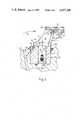
- FIG. 1is a part sectional side elevation of a forward attack pick in accordance with the first aspect of the invention, and a pick and box combination in accordance with the second aspect of the invention;
- FIG. 2corresponds to FIG. 1 but shows a radial type pick and a slightly modified pick box
- FIG. 3corresponds to FIG. 1 but shows another form of pick and pick box
- FIG. 4is a plan view of the pick box of FIG. 3;
- FIG. 5corresponds to FIG. 1 but shows another form of pick and pick box
- FIG. 6also corresponds to FIG. 1 but shows yet another form of pick and pick box.
- a mineral cutter pick 1comprises a head 2 terminating at one end thereof in a hard material tip 3, with an integral shank 4 extending from the head 2 in a direction away from the tip 3.
- the shankis rectangular, in FIGS. 3 and 6 the shank is circular, and in FIG. 5 the shank is frusto-conical.
- a shoulder 5 located and extending rearwardly (having regard to direction of movement, in use, of the pick 1 which is indicated by the arrow A)is provided on the head 2 in the vicinity of the transition between the head and the shank, and a bore 6 extends through the shoulder 5.
- the head 2is also provided with a second shoulder 5A extending forwardly.
- the bore 6has a longitudinal axis 7 which in the embodiment of FIG. 1 extends generally in the longitudinal direction of the pick, as illustrated by the axis 8 of the shank 4, although tapering towards the axis 8 so that, in use, with the pick 1 mounted on a rotary cutting head, the pick removes mineral to leave a mineral seam 9, with the axis 7 intersecting the seam 9 at a point 10.
- the axis 7tapers at a more pronounced angle to the axis 8.
- the pick 1is releasably locatable by a known latching device 4A carried by its shank 4 in a correspondingly section aperture 11 in a pick box 12 having a seating surface 13 engaged by the shoulder(s) 5.
- the box 12is also provided with a water supply bore 14 connectable at one end to a source of pressurized water and terminating at its other end in a water spray or jet nozzle 15 located beneath the shoulder 5 such that water emitted by the nozzle 15 passes through the bore 6 and along, or generally along the axis 7 to the area behind the tip 3, generally in the vicinity of the point 10, to reduce, if not eliminate any incendive sparking tendencies which occur not infrequently when the pick 1 inadvertently leaves a coal etc., seam and strikes a harder mineral, e.g. sand stone, and also to have a dust suppressing effect, and, if used in a high pressure mode, possibly to give a stress relieving slot ahead of and/or behind the pick.
- a water supply bore 14connectable at one end to a source of pressurized water and terminating at its other end in a water spray or jet nozzle 15 located beneath the shoulder 5 such that water emitted by the nozzle 15 passes through the bore 6 and along, or generally
- the shank 4is circular and stepped, to fit a correspondingly circular and stepped aperture 11 in the pick box 12.
- the pick 1is again of the forward attack type but shank 4 is frusto-conically tapered.
- the pick 1has a circular section shank 4 and, in contrast to the previous embodiments, does not fit directly into the pick box aperture but fits into an adaptor 16.
- the pickis provided with a forward shoulder 5A this likewise could be provided with a through bore, and the receiving pick box with a second water emitting nozzle aligned with this second through bore, to provide a water spray or jet in advance of the cutting tip.
Landscapes
- Engineering & Computer Science (AREA)
- Mining & Mineral Resources (AREA)
- Mechanical Engineering (AREA)
- Life Sciences & Earth Sciences (AREA)
- General Life Sciences & Earth Sciences (AREA)
- Geochemistry & Mineralogy (AREA)
- Geology (AREA)
- Processing Of Stones Or Stones Resemblance Materials (AREA)
- Nozzles (AREA)
Abstract
Description
Claims (9)
Applications Claiming Priority (2)
| Application Number | Priority Date | Filing Date | Title |
|---|---|---|---|
| GB8504668 | 1985-02-22 | ||
| GB858504668AGB8504668D0 (en) | 1985-02-22 | 1985-02-22 | Mineral cutter pick |
Publications (1)
| Publication Number | Publication Date |
|---|---|
| US4657308Atrue US4657308A (en) | 1987-04-14 |
Family
ID=10574948
Family Applications (1)
| Application Number | Title | Priority Date | Filing Date |
|---|---|---|---|
| US06/823,319Expired - LifetimeUS4657308A (en) | 1985-02-22 | 1986-01-28 | Mineral cutter pick |
Country Status (5)
| Country | Link |
|---|---|
| US (1) | US4657308A (en) |
| EP (1) | EP0193268B1 (en) |
| DE (1) | DE3663711D1 (en) |
| GB (1) | GB8504668D0 (en) |
| ZA (1) | ZA86576B (en) |
Cited By (22)
| Publication number | Priority date | Publication date | Assignee | Title |
|---|---|---|---|---|
| US6247759B1 (en)* | 1999-06-08 | 2001-06-19 | Kennametal Pc Inc. | Cutting tool assembly with replaceable spray nozzle |
| DE19839440C2 (en)* | 1997-09-06 | 2003-10-09 | Hydra Tools Internat Ltd | Chisel holder for a cutting tool |
| GB2418214A (en)* | 2004-09-15 | 2006-03-22 | Sandvik Intellectual Property | Cutting Tool With Nozzle For Spraying Water On Cutter Bit |
| US20080048484A1 (en)* | 2006-08-11 | 2008-02-28 | Hall David R | Shank for an Attack Tool |
| US20080258536A1 (en)* | 2006-08-11 | 2008-10-23 | Hall David R | High-impact Resistant Tool |
| US20080309146A1 (en)* | 2006-08-11 | 2008-12-18 | Hall David R | Degradation assembly shield |
| US20090267403A1 (en)* | 2006-08-11 | 2009-10-29 | Hall David R | Resilient Pick Shank |
| US20100237135A1 (en)* | 2006-08-11 | 2010-09-23 | Schlumberger Technology Corporation | Methods For Making An Attack Tool |
| US20100263939A1 (en)* | 2006-10-26 | 2010-10-21 | Hall David R | High Impact Resistant Tool with an Apex Width between a First and Second Transitions |
| US20110080036A1 (en)* | 2007-05-15 | 2011-04-07 | Schlumberger Technology Corporation | Spring Loaded Pick |
| US8033616B2 (en) | 2006-08-11 | 2011-10-11 | Schlumberger Technology Corporation | Braze thickness control |
| US8136887B2 (en) | 2006-08-11 | 2012-03-20 | Schlumberger Technology Corporation | Non-rotating pick with a pressed in carbide segment |
| WO2013021283A3 (en)* | 2011-08-08 | 2014-01-23 | Esco Hydra (Uk) Limited | Cutter tool |
| US8701799B2 (en) | 2009-04-29 | 2014-04-22 | Schlumberger Technology Corporation | Drill bit cutter pocket restitution |
| CN104040112A (en)* | 2011-11-11 | 2014-09-10 | 米诺沃讯有限公司 | Mineral cutter pick etc |
| DE102014103406A1 (en) | 2013-03-15 | 2014-09-18 | Joy Mm Delaware, Inc. | Milling head for a longwall cutting machine |
| US9051795B2 (en) | 2006-08-11 | 2015-06-09 | Schlumberger Technology Corporation | Downhole drill bit |
| DE102014112964A1 (en)* | 2014-09-09 | 2016-03-10 | Betek Gmbh & Co. Kg | Chisel, in particular round shank chisel |
| US9366089B2 (en) | 2006-08-11 | 2016-06-14 | Schlumberger Technology Corporation | Cutting element attached to downhole fixed bladed bit at a positive rake angle |
| US9915102B2 (en) | 2006-08-11 | 2018-03-13 | Schlumberger Technology Corporation | Pointed working ends on a bit |
| WO2018050900A1 (en) | 2016-09-19 | 2018-03-22 | Minnovation Limited | Cutter pick assembly with water spray assembly |
| USD960215S1 (en) | 2020-09-16 | 2022-08-09 | Gary E. Weaver | Shear pick |
Families Citing this family (1)
| Publication number | Priority date | Publication date | Assignee | Title |
|---|---|---|---|---|
| GB9025934D0 (en)* | 1990-11-29 | 1991-01-16 | Hydra Tools Int Plc | Mineral mining equipment etc |
Citations (10)
| Publication number | Priority date | Publication date | Assignee | Title |
|---|---|---|---|---|
| DE875332C (en)* | 1951-12-25 | 1953-04-30 | Gewerk Eisenhuette Westfalia | Sole chisel for coal planer |
| GB996962A (en)* | 1960-09-20 | 1965-06-30 | Coal Industry Patents Ltd | Rotary cutter unit for a mineral-mining machine |
| DE2134893A1 (en)* | 1970-07-24 | 1972-02-03 | Coal Industry (Patents) Ltd., London | Circulating cutter for mining machines |
| GB1573505A (en)* | 1977-11-24 | 1980-08-28 | Padley & Venables Ltd | Pick holder assemblies and pick holding blocks therefor |
| GB2043746A (en)* | 1978-12-12 | 1980-10-08 | Hoverdale Eng Ltd | Pick box |
| GB2104945A (en)* | 1981-09-04 | 1983-03-16 | Green And Bingham Limited | Dusting suppressing mineral mining cutter head |
| DE3202315A1 (en)* | 1982-01-26 | 1983-07-28 | Gebr. Eickhoff, Maschinenfabrik U. Eisengiesserei Mbh, 4630 Bochum | Loosening tool for a winning machine in underground mining |
| DE3334031A1 (en)* | 1983-09-21 | 1985-04-04 | Bergwerksverband Gmbh, 4300 Essen | Pick with pick head designed for assistance by high-pressure liquid jets |
| US4569558A (en)* | 1983-07-25 | 1986-02-11 | The Regents Of The University Of California | Drag bit construction |
| US4573744A (en)* | 1980-11-24 | 1986-03-04 | Padley & Venables Limited | Pick and the combination of a pick and holder |
- 1985
- 1985-02-22GBGB858504668Apatent/GB8504668D0/enactivePending
- 1986
- 1986-01-22EPEP86300421Apatent/EP0193268B1/ennot_activeExpired
- 1986-01-22DEDE8686300421Tpatent/DE3663711D1/ennot_activeExpired
- 1986-01-24ZAZA86576Apatent/ZA86576B/enunknown
- 1986-01-28USUS06/823,319patent/US4657308A/ennot_activeExpired - Lifetime
Patent Citations (12)
| Publication number | Priority date | Publication date | Assignee | Title |
|---|---|---|---|---|
| DE875332C (en)* | 1951-12-25 | 1953-04-30 | Gewerk Eisenhuette Westfalia | Sole chisel for coal planer |
| GB996962A (en)* | 1960-09-20 | 1965-06-30 | Coal Industry Patents Ltd | Rotary cutter unit for a mineral-mining machine |
| DE2134893A1 (en)* | 1970-07-24 | 1972-02-03 | Coal Industry (Patents) Ltd., London | Circulating cutter for mining machines |
| GB1309005A (en)* | 1970-07-24 | 1973-03-07 | Coal Industry Patents Ltd | Rotary cutters for mineral mining machines |
| GB1573505A (en)* | 1977-11-24 | 1980-08-28 | Padley & Venables Ltd | Pick holder assemblies and pick holding blocks therefor |
| GB2043746A (en)* | 1978-12-12 | 1980-10-08 | Hoverdale Eng Ltd | Pick box |
| US4573744A (en)* | 1980-11-24 | 1986-03-04 | Padley & Venables Limited | Pick and the combination of a pick and holder |
| US4573744B1 (en)* | 1980-11-24 | 1989-07-25 | ||
| GB2104945A (en)* | 1981-09-04 | 1983-03-16 | Green And Bingham Limited | Dusting suppressing mineral mining cutter head |
| DE3202315A1 (en)* | 1982-01-26 | 1983-07-28 | Gebr. Eickhoff, Maschinenfabrik U. Eisengiesserei Mbh, 4630 Bochum | Loosening tool for a winning machine in underground mining |
| US4569558A (en)* | 1983-07-25 | 1986-02-11 | The Regents Of The University Of California | Drag bit construction |
| DE3334031A1 (en)* | 1983-09-21 | 1985-04-04 | Bergwerksverband Gmbh, 4300 Essen | Pick with pick head designed for assistance by high-pressure liquid jets |
Non-Patent Citations (2)
| Title |
|---|
| Acco Babcock Inc. "Thru-Flush", 10/1982. |
| Acco Babcock Inc. Thru Flush , 10/1982.* |
Cited By (46)
| Publication number | Priority date | Publication date | Assignee | Title |
|---|---|---|---|---|
| DE19839440C2 (en)* | 1997-09-06 | 2003-10-09 | Hydra Tools Internat Ltd | Chisel holder for a cutting tool |
| US6247759B1 (en)* | 1999-06-08 | 2001-06-19 | Kennametal Pc Inc. | Cutting tool assembly with replaceable spray nozzle |
| AU2005204228B2 (en)* | 2004-09-15 | 2010-03-04 | Sandvik Intellectual Property Ab | Cutting tool with nozzle for spraying water on cutter bit |
| GB2418214A (en)* | 2004-09-15 | 2006-03-22 | Sandvik Intellectual Property | Cutting Tool With Nozzle For Spraying Water On Cutter Bit |
| GB2418214B (en)* | 2004-09-15 | 2006-11-01 | Sandvik Intellectual Property | Cutting tool with nozzle for spraying water on cutter bit |
| DE102005041509B4 (en)* | 2004-09-15 | 2014-04-24 | Sandvik Intellectual Property Ab | Cutting tool with nozzle for spraying water onto a cutting bit |
| US8136887B2 (en) | 2006-08-11 | 2012-03-20 | Schlumberger Technology Corporation | Non-rotating pick with a pressed in carbide segment |
| US20080258536A1 (en)* | 2006-08-11 | 2008-10-23 | Hall David R | High-impact Resistant Tool |
| US7635168B2 (en)* | 2006-08-11 | 2009-12-22 | Hall David R | Degradation assembly shield |
| US20080309146A1 (en)* | 2006-08-11 | 2008-12-18 | Hall David R | Degradation assembly shield |
| US20100237135A1 (en)* | 2006-08-11 | 2010-09-23 | Schlumberger Technology Corporation | Methods For Making An Attack Tool |
| US9366089B2 (en) | 2006-08-11 | 2016-06-14 | Schlumberger Technology Corporation | Cutting element attached to downhole fixed bladed bit at a positive rake angle |
| US9708856B2 (en) | 2006-08-11 | 2017-07-18 | Smith International, Inc. | Downhole drill bit |
| US8033616B2 (en) | 2006-08-11 | 2011-10-11 | Schlumberger Technology Corporation | Braze thickness control |
| US9051795B2 (en) | 2006-08-11 | 2015-06-09 | Schlumberger Technology Corporation | Downhole drill bit |
| US9915102B2 (en) | 2006-08-11 | 2018-03-13 | Schlumberger Technology Corporation | Pointed working ends on a bit |
| US20080048484A1 (en)* | 2006-08-11 | 2008-02-28 | Hall David R | Shank for an Attack Tool |
| US8449040B2 (en) | 2006-08-11 | 2013-05-28 | David R. Hall | Shank for an attack tool |
| US8454096B2 (en) | 2006-08-11 | 2013-06-04 | Schlumberger Technology Corporation | High-impact resistant tool |
| US8500210B2 (en) | 2006-08-11 | 2013-08-06 | Schlumberger Technology Corporation | Resilient pick shank |
| US10378288B2 (en) | 2006-08-11 | 2019-08-13 | Schlumberger Technology Corporation | Downhole drill bit incorporating cutting elements of different geometries |
| US20090267403A1 (en)* | 2006-08-11 | 2009-10-29 | Hall David R | Resilient Pick Shank |
| US10029391B2 (en) | 2006-10-26 | 2018-07-24 | Schlumberger Technology Corporation | High impact resistant tool with an apex width between a first and second transitions |
| US20100263939A1 (en)* | 2006-10-26 | 2010-10-21 | Hall David R | High Impact Resistant Tool with an Apex Width between a First and Second Transitions |
| US8960337B2 (en) | 2006-10-26 | 2015-02-24 | Schlumberger Technology Corporation | High impact resistant tool with an apex width between a first and second transitions |
| US8365845B2 (en) | 2007-02-12 | 2013-02-05 | Hall David R | High impact resistant tool |
| US8342611B2 (en) | 2007-05-15 | 2013-01-01 | Schlumberger Technology Corporation | Spring loaded pick |
| US20110080036A1 (en)* | 2007-05-15 | 2011-04-07 | Schlumberger Technology Corporation | Spring Loaded Pick |
| US8701799B2 (en) | 2009-04-29 | 2014-04-22 | Schlumberger Technology Corporation | Drill bit cutter pocket restitution |
| EA027050B1 (en)* | 2011-08-08 | 2017-06-30 | Эско Хайдра (Юк) Лимитед | Cutter tool |
| US9206686B2 (en) | 2011-08-08 | 2015-12-08 | Esco Hydra (Uk) Limited | Cutter tool |
| CN103732860B (en)* | 2011-08-08 | 2016-08-31 | 埃斯科海德拉(英国)有限公司 | cutting tool |
| AU2012293424B2 (en)* | 2011-08-08 | 2016-12-15 | Esco Hydra (Uk) Limited | Cutter tool |
| CN103732860A (en)* | 2011-08-08 | 2014-04-16 | 埃斯科海德拉(英国)有限公司 | cutting tool |
| WO2013021283A3 (en)* | 2011-08-08 | 2014-01-23 | Esco Hydra (Uk) Limited | Cutter tool |
| CN104040112B (en)* | 2011-11-11 | 2016-02-10 | 米诺沃讯有限公司 | Mining cutter pick |
| AU2012335367B2 (en)* | 2011-11-11 | 2016-02-25 | Minnovation Limited | Mineral cutter pick etc |
| US9140121B2 (en)* | 2011-11-11 | 2015-09-22 | Minnovation Limited | Mineral cutter pick etc |
| US20140312678A1 (en)* | 2011-11-11 | 2014-10-23 | Minnovation Limited | Mineral Cutter Pick Etc |
| RU2606720C2 (en)* | 2011-11-11 | 2017-01-10 | Минновэйшн Лимитед | Cutting machine cutter for mineral deposits and such |
| CN104040112A (en)* | 2011-11-11 | 2014-09-10 | 米诺沃讯有限公司 | Mineral cutter pick etc |
| DE102014103406A1 (en) | 2013-03-15 | 2014-09-18 | Joy Mm Delaware, Inc. | Milling head for a longwall cutting machine |
| DE102014112964A1 (en)* | 2014-09-09 | 2016-03-10 | Betek Gmbh & Co. Kg | Chisel, in particular round shank chisel |
| WO2018050900A1 (en) | 2016-09-19 | 2018-03-22 | Minnovation Limited | Cutter pick assembly with water spray assembly |
| US10830042B2 (en) | 2016-09-19 | 2020-11-10 | Minnovation Limited | Cutter pick assembly with water spray assembly |
| USD960215S1 (en) | 2020-09-16 | 2022-08-09 | Gary E. Weaver | Shear pick |
Also Published As
| Publication number | Publication date |
|---|---|
| EP0193268B1 (en) | 1989-05-31 |
| ZA86576B (en) | 1986-09-24 |
| DE3663711D1 (en) | 1989-07-06 |
| EP0193268A1 (en) | 1986-09-03 |
| GB8504668D0 (en) | 1985-03-27 |
Similar Documents
| Publication | Publication Date | Title |
|---|---|---|
| US4657308A (en) | Mineral cutter pick | |
| US8523289B2 (en) | Retention assembly for cutting bit | |
| AU731941B2 (en) | Point attack tooling system for mineral winning | |
| US8523290B2 (en) | Rotatable cutting tool-tool holder-base assembly | |
| US4280735A (en) | Non-rotary mining cutter with recessed nozzle insert | |
| CN101956554B (en) | Water spray assembly and pick box employing same | |
| US4540056A (en) | Cutter assembly | |
| US3268259A (en) | Coal-cutter picks | |
| US20090091177A1 (en) | Mineral cutter system | |
| US5319855A (en) | Mineral cutter tip and pick | |
| US6257672B1 (en) | Clip for retaining a water spray nozzle within a pick box of a cutting head | |
| EP0086040B1 (en) | Mineral cutting tool | |
| US4443038A (en) | Mineral cutter tool having water emission deflection surface | |
| CA2056804C (en) | Mineral mining equipment etc. | |
| US4652056A (en) | Mineral cutting device | |
| US6536847B2 (en) | Pick box for housing a mineral cutter pick | |
| US3666321A (en) | Holder for cutting tip of milling cutter machine | |
| GB2041043A (en) | Improvements Relating to Mineral Mining Tools | |
| GB2182698A (en) | Mineral cutter pick | |
| US3507345A (en) | Cutter bit | |
| CN113748249A (en) | Tool rack assembly | |
| GB2113743A (en) | Improvements in or relating to mineral cutter tools | |
| GB2141765A (en) | Mineral cutter pick, box, and pick and box combination | |
| GB2137263A (en) | Mineral cutter pick and box | |
| GB2144787A (en) | Mineral cutter pick and box combination and rotary cutting head incorporating same |
Legal Events
| Date | Code | Title | Description |
|---|---|---|---|
| AS | Assignment | Owner name:HALL & PICKLES LIMITED, HYDRA WORKS, ECCLESFIELD, Free format text:ASSIGNMENT OF ASSIGNORS INTEREST.;ASSIGNOR:CLAPHAM, WILLIAM S.;REEL/FRAME:004527/0408 Effective date:19860106 | |
| STCF | Information on status: patent grant | Free format text:PATENTED CASE | |
| AS | Assignment | Owner name:HYDRA TOOLS INTERNATIONAL LIMITED, A COMPANY OF EN Free format text:ASSIGNMENT OF ASSIGNORS INTEREST.;ASSIGNOR:HALL & PICKLES LIMITED, A CORP. OF ENGLAND;REEL/FRAME:005224/0031 Effective date:19880212 | |
| AS | Assignment | Owner name:HYDRA TOOLS INTERNATIONAL PLC LIMITED Free format text:CHANGE OF NAME;ASSIGNOR:HYDRA TOOLS INTERANTIONAL LIMITED;REEL/FRAME:005216/0181 Effective date:19880309 | |
| FEPP | Fee payment procedure | Free format text:PAYOR NUMBER ASSIGNED (ORIGINAL EVENT CODE: ASPN); ENTITY STATUS OF PATENT OWNER: LARGE ENTITY | |
| FPAY | Fee payment | Year of fee payment:4 | |
| FPAY | Fee payment | Year of fee payment:8 | |
| FPAY | Fee payment | Year of fee payment:12 | |
| AS | Assignment | Owner name:HYDRA TOOLS INTERNATIONAL LIMITED, UNITED KINGDOM Free format text:CHANGE OF NAME;ASSIGNOR:HYDRA TOOLS INTERNATIONAL PLC;REEL/FRAME:017057/0196 Effective date:20051213 | |
| AS | Assignment | Owner name:HYDRA MINING TOOLS INTERNATIONAL LIMITED, UNITED K Free format text:ASSIGNMENT OF ASSIGNORS INTEREST;ASSIGNOR:HYDRA TOOLS INTERNATIONAL LIMITED;REEL/FRAME:017057/0629 Effective date:20001110 |