US4657112A - Mast construction for pedestal scaffold - Google Patents
Mast construction for pedestal scaffoldDownload PDFInfo
- Publication number
- US4657112A US4657112AUS06/856,050US85605086AUS4657112AUS 4657112 AUS4657112 AUS 4657112AUS 85605086 AUS85605086 AUS 85605086AUS 4657112 AUS4657112 AUS 4657112A
- Authority
- US
- United States
- Prior art keywords
- mast
- mast section
- section
- sections
- secured
- Prior art date
- Legal status (The legal status is an assumption and is not a legal conclusion. Google has not performed a legal analysis and makes no representation as to the accuracy of the status listed.)
- Expired - Lifetime
Links
Images


Classifications
- B—PERFORMING OPERATIONS; TRANSPORTING
- B66—HOISTING; LIFTING; HAULING
- B66F—HOISTING, LIFTING, HAULING OR PUSHING, NOT OTHERWISE PROVIDED FOR, e.g. DEVICES WHICH APPLY A LIFTING OR PUSHING FORCE DIRECTLY TO THE SURFACE OF A LOAD
- B66F11/00—Lifting devices specially adapted for particular uses not otherwise provided for
- B66F11/04—Lifting devices specially adapted for particular uses not otherwise provided for for movable platforms or cabins, e.g. on vehicles, permitting workmen to place themselves in any desired position for carrying out required operations
Definitions
- This inventionrelates to movable pedestal type scaffold units such as shown in U.S. Pat. No. 4,397,373, issued Aug. 9, 1983, and application Ser. No. 781,221, filed Sept. 27, 1985, and now U.S. Pat. No. 4,592,447, issued June 3, 1986.
- Personnel lifts of the pedestal type exemplified by the above patentstypically have an upright mast mounted on a relatively small base member, and a work cage mounted on the mast for vertical movement.
- the present inventionis particularly directed to an improved construction of the vertically extendible mast of such scaffold units.
- the mast of the U.S. Pat. No. 4,397,373comprises a plurality of side-by-side parallel frame sections arranged to extend vertically relative to each other.
- these mast sectionscomprise opposed vertical extruded aluminum channels connected together by a plurality of cross pieces.
- the weight of a scaffold unit of this typeis an important consideration since these units must be moved from place to place and loaded onto and off of trucks by the workmen using the scaffolds.
- the cost of constructionis also an important consideration in enabling the scaffold units to be sold at a price that can be afforded by purchasers.
- the weight of the mast sectionsis, of course, also related to the cost of manufacture in that the more the weight, the more the material that is used in the mast.
- the mast of the Ser. No. 781,221 applicationcomprises a plurality of telescopically arranged aluminum extrusions. Again, such a mast is relatively heavy and expensive to manufacture. In particular, aluminum extrusions require costly dies for the extrusion process and the wall thickness of an extruded column must inherently be relatively great. The outermost mast sections in particular will have considerable weight and be quite high in manufacturing cost.
- the main object of the present inventionis to provide a pedestal type scaffold with a extendable mast which is much lighter in weight and more economical in manufacture than those of the prior art.
- the present inventionis directed overcoming the problems set forth above and towards fulfilling the above object.
- the present inventionprovides a pedestal scaffold having a base member, a mast mounted on the base member, and a work cage carried by the upper end of the mast, the mast including a plurality of nested tubular mast sections in which the majority of the mast sections are made of thin-walled sheet aluminum, with rounded corners and vertical stiffening ribs on each side of the section.
- Plastic slide blocks at the upper and lower ends of the mast sections and at the four corners of the mast sectionshave mast engaging surfaces complimentary in shape to the rounded corners of the mast sections.
- chains and strapsfit into the narrow spaces between the mast sections for raising and lowering of the mast sections.
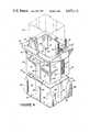
- FIG. 1is a perspective view of a personnel lift with a telescopic mast constructed in accordance with the present invention, the mast shown in retracted position.
- FIG. 2is a view as in FIG. 1 with the mast of FIG. 1 shown in an extended position.
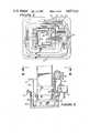
- FIG. 3is a simplified cross-sectional view of the mast of FIG. 1, showing the various stages thereof and the apparatus for extending the mast.
- FIG. 4is a perspective view of one of the stages of the mast of FIG. 1.
- FIG. 5is a vertical sectional view through portions of the three innermost stages of the mast of FIG. 1.
- FIG. 6is a sectional view of the mast of FIG. 1.
- FIG. 1shows a movable pedestal scaffold 10 having a base member 11 with wheels 12 at either end of the base member.
- outriggers 13, each with a vertically adjustable ground engaging member 14,are attachable to the base member 11 to provide an extended area of support for the unit.
- a vertical mast 16extends upwardly.
- the mast 16comprises six telescoped mast sections 16a-f, the outermost mast section 16a being mounted on the base member 11.
- a work cage 17is mounted, by cantilever arm 18, to the upper end of the innermost mast section 16f.
- the work cageis spaced horizontally from the innermost mast section 16f and extends downwardly from the upper end of the mast section 16f and along one side of the mast.
- a ladder 19 on the base member 11enables a workman to climb up to the work cage when the cage is at its downwardly retracted position of FIG. 1.
- apparatus 20will include a hydraulic reservoir, a fluid pump and batteries for driving the pump.
- FIG. 3shows in simplified form the apparatus for vertical extension of the sections 16b-f of mast 16.
- a extensible fluid-operated ram 21is vertically disposed centrally of the mast 16, with its piston member 22 secured to the lower end of the outermost mast section 16a and with its cylinder member 23 secured to the lower end of the next innermost mast section 16b.
- a sprocket 24is mounted on the upper end of ram 21 and chain 26 extends around sprocket 24 with one end of the chain 26 being connected to the lower end of the outermost mast section 16a and with the other end of the chain being connected to the lower end of mast section 16c.
- Additional sprockets 27, 28 and 29are mounted on the upper ends of mast sections 16c, 16d and 16e, respectively.
- Chain 31extends from the upper end of mast section 16b up over sprocket 27 and then down to the lower end of mast section 16d.
- chain 32runs from the upper end of mast section 16c upward over sprocket 28 and down to the lower end of mast section 16e, while chain 33 runs from the upper end of mast section 16d up over sprocket 29 and down to the lower end of the innermost mast section 16f.
- the chains and sprockets described aboveare preferably doubled for the stages to equalize loading forces and to provide backup support in the event of a chain failure.
- a plurality of fabric straps 36, 37, 38 and 39interconnect the mast sections on the side of the mast opposite to the chains described above, with each strap being secured to the upper end of a mast section and extending down to and around the lower end of the next innermost mast section and then being secured to the lower end of the then next innermost mast section.
- strap 36is secured to mast section 16a, extends down around the lower end of mast section 16b and is secured to the lower end of mast section 16c.
- the mast 16will retract downwardly with release of hydraulic fluid from the ram 21 causing mast secsection 16b to move downwardly.
- the weight of the work cagewill cause the other mast sections to lower as the various sprockets 24, 27, 28 and 29 move downwardly.
- the straps 36-39merely follow the downward movement of the mast sections and bear no stress.
- the straps 36-39will serve to prevent retraction of lower mast sections. For example, suppose mast section 16d were to hang up on some obstruction as it was moving downwardly. The lower end of mast section 16d would then be "fixed” against further downward movement. Since the upper end of the outermost mast section 16a is likewise fixed against vertical movement, straps 36 and 37 will support mast sections 16b and 16c and prevent them from moving downwardly. Chains 32 and 33 will likewise prevent any downward movement of the mast sections 16e and 16f above the hung-up mast section 16d.
- any mast sectionis externally prevented from retracting downwardly, the straps and chains will prevent all of the other mast sections from retracting.
- the use of straps as disclosedis very advantageous since they are strong, flexible and can fit easily into the very restricted spaces between the mast sections. In case of such a hang up, the operator can then cause the mast to extend upwardly so that the obstruction can be removed. After that, retraction can take place in a normal manner.
- FIGS. 4-6illustrate the details of the sections of the mast 12.
- FIG. 4illustrates, in perspective, mast section 16c.
- mast section 16cis made from two identical U-shaped channels 41 and 42 formed from thin-walled sheet aluminum.
- personnel liftshave been built in accordance with the present invention with a 38 foot maximum platform height and using 5052 H32 sheet aluminum with a 0.060 inch wall thickness for the sheet aluminum mast sections.
- Each U-shaped channel 41 and 42is formed will substantially rounded corners 43 and is deformed from the plane of the base side 44 of the channel to provide a stiffening rib 46 extending the full height of the channel.
- the legs 47 of the channelare also deformed from the planes of the legs to provide offset end portions 48 parallel to the planes of the legs.
- the two channel sections 41 and 42are placed with the offset portions 48 adjacent to each other and are joined together by rivets 49 along the height of the mast section. The offset portions thus form a stiffening rib.
- An upper collar 51preferably of cast aluminum, surrounds the upper end of the joined together sheet aluminum channels 41 and 42, the collar 51 having vertical flanges 52, to which the channels 41 and 42 are secured by rivets 53, and an outwardly projecting horizontal flange 54.
- the collar 51protects the upper edges of the sheet aluminum channels and maintains the rectangularity of the mast section.
- the collar 51supports sprocket 27 and provides a rigid member to which chains 32 are secured.
- the collar 51provides a rigid member for attachment of strap 38.
- a similar, but inverted, lower collar 56extends around the inside of the joined together sheet aluminum channels and is secured thereto by rivets 57.
- This collarlikewise protects the lower edges of the channels 41 and 42, maintains the rectangularity of the mast section, and provides a rigid member for attachment to the strap 36 (not shown in FIG. 4) secured thereto.
- the lower collar 51also provides a rigid member to which chains 31, 32 and 33 may be secured.
- Each of the aluminum sheet mast sections 16b-ehas an upper and lower collar 51, 56 generally as described in connection with mast section 16c.
- the outermost mast section 16ahas an upper collar 51 thereon, but no lower collar 56 is needed since the attachment of the mast section 16a to the frame member 11 serves the purpose.
- the preferred embodiment shown hereinhas an extruded aluminum tube as the innermost mast section 16f. Because of the relatively small cross-sectional modulus of this innermost mast section, a thicker walled aluminum sheet would be necessary to withstand the high bending stresses. Further, the mast was designed so that the innermost mast section has a 4 ⁇ 4 inch size which is a standard, commercially available aluminum extrusion, with a 1/8 inch wall thickness.
- the mast sectionswill range in height from about 7 feet for mast section 16a to about 51/2 feet for the innermost mast section 16f.
- the cross-sectional area of the mast sectionsranges from about 9 ⁇ 12 inches for mast section 16a to 4 ⁇ 4 inches for the mast section 16f.
- the mast section 16chas a set of four plastic slide blocks 61 mounted on the upper end of the mast section, with one of the slide blocks being mounted at each of the four inside corners of the mast section and secured thereto, as by screws 62, the slide blocks being approximately 6 inches in height.
- Each slide blockhas an outer surface 63 of a shape complementary to the shape of the inside corner of the mast section to which it is secured and an inner surface 64 of a shape complementary to the shape of the outside corner of the next inner mast section 16d adjacent thereto.
- the slide blocksare made of UHMW (ultra high molecular weight) high density polyethylene.
- the slide blocksare placed at the corners of the mast sections where the mast sections are strongest and where the least amount of deformation will occur when the mast is under load.
- the rounded corners of the mast sections and the complementary shaped slide blocksserve to distribute the bearing pressure on the slide blocks and to distribute the force from the slide blocks onto a relatively large area of the thin-walled aluminum sheet mast sections.
- mast section 16chas a set of four slide blocks 66 mounted on the lower end of the mast section at the outside of each of the four corners.
- Slide blocks 66each have an inner surface 67 of a shape complementary to the shape of the outside corner of mast section 16c to which it is mounted and an outer surface 68 of a shape complementary to the shape of the inner corner of the next mast section adjacent thereto.
- the shape of the slide blocksspreads the forces over a substantial area of the aluminum sheet instead of concentrating them at a sharp corner.
- the present inventionprovides a mast that is relatively light in weight and relatively inexpensive to manufacture because it is largely made out of thin walled aluminum sheet rather than thicker and considerably more expensive aluminum extrusions.
- the relatively large rectangular cross-section of the mast sectionprovides for a very efficient distribution of material while providing a very rigid mast which will resist bending forces from the cantilever mounted work cage and torsional forces impared by reaction forces by a workman working to his side while in the cage.
Landscapes
- Engineering & Computer Science (AREA)
- Structural Engineering (AREA)
- Life Sciences & Earth Sciences (AREA)
- Geology (AREA)
- Mechanical Engineering (AREA)
- Movable Scaffolding (AREA)
Abstract
Description
Claims (7)
Priority Applications (5)
| Application Number | Priority Date | Filing Date | Title |
|---|---|---|---|
| US06/856,050US4657112A (en) | 1986-04-25 | 1986-04-25 | Mast construction for pedestal scaffold |
| AU68850/87AAU586534B2 (en) | 1986-04-25 | 1987-02-16 | Mast construction for pedestal scaffold |
| DE8787301690TDE3778751D1 (en) | 1986-04-25 | 1987-02-26 | MAST CONSTRUCTION FOR WORKING PLATFORM. |
| EP87301690AEP0244060B1 (en) | 1986-04-25 | 1987-02-26 | Mast construction for pedestal scaffold |
| JP62055491AJPS62276162A (en) | 1986-04-25 | 1987-03-12 | Trapezoidal scaffold |
Applications Claiming Priority (1)
| Application Number | Priority Date | Filing Date | Title |
|---|---|---|---|
| US06/856,050US4657112A (en) | 1986-04-25 | 1986-04-25 | Mast construction for pedestal scaffold |
Publications (1)
| Publication Number | Publication Date |
|---|---|
| US4657112Atrue US4657112A (en) | 1987-04-14 |
Family
ID=25322751
Family Applications (1)
| Application Number | Title | Priority Date | Filing Date |
|---|---|---|---|
| US06/856,050Expired - LifetimeUS4657112A (en) | 1986-04-25 | 1986-04-25 | Mast construction for pedestal scaffold |
Country Status (5)
| Country | Link |
|---|---|
| US (1) | US4657112A (en) |
| EP (1) | EP0244060B1 (en) |
| JP (1) | JPS62276162A (en) |
| AU (1) | AU586534B2 (en) |
| DE (1) | DE3778751D1 (en) |
Cited By (51)
| Publication number | Priority date | Publication date | Assignee | Title |
|---|---|---|---|---|
| US4783934A (en)* | 1986-11-21 | 1988-11-15 | United Production Services, Inc. | Free-standing assembly and method for making same |
| EP0346246A1 (en)* | 1988-06-10 | 1989-12-13 | Reel S.A. | Telescopic mast enabling maintenance of position and manoeuvring of a basket or a working platform, the displacements of which are controlled by a travelling crane |
| DE8903568U1 (en)* | 1989-03-17 | 1990-04-19 | Ramani, Zyber, 1000 Berlin | Work platform |
| US5115606A (en)* | 1990-09-24 | 1992-05-26 | Ingersoll-Rand Company | Extension cable for telescopic tower |
| US5168679A (en)* | 1990-09-10 | 1992-12-08 | The Will-Burt Company | Telescoping mast assembly |
| US5209433A (en)* | 1991-01-28 | 1993-05-11 | Brown & Root U.S.A., Inc. | Mobile rocket service tower |
| US5279084A (en)* | 1991-05-17 | 1994-01-18 | Japan Skyrobot Co., Ltd. | Movement mechanism of telescopic column |
| US5327690A (en)* | 1990-10-08 | 1994-07-12 | Kajima Corporation | Erection workbench for constructing a frame |
| WO1997015522A1 (en)* | 1995-10-23 | 1997-05-01 | Upright, Inc. | Personnel lift with movable cage assembly |
| US5718087A (en)* | 1996-05-02 | 1998-02-17 | The Will-Burt Company | Telescoping mast assembly |
| US5803204A (en)* | 1995-10-23 | 1998-09-08 | Upright, Inc. | Personnel lift with clamshell cage assembly |
| US6174124B1 (en)* | 1996-10-04 | 2001-01-16 | Crown Equipment Corporation | Load trays for personnel carrying vehicles |
| EP1079046A3 (en)* | 1999-08-26 | 2003-02-12 | The Will-Burt Company | Low profile lift mounting arrangement for telescoping mast |
| US20030213766A1 (en)* | 2002-05-15 | 2003-11-20 | Komatsu Utility Europe S.P.A. | Telescopic arm |
| US20040123328A1 (en)* | 2002-12-20 | 2004-06-24 | Ecamsecure, Inc. | Mobile surveillance vehicle |
| US20040258404A1 (en)* | 2000-02-10 | 2004-12-23 | Brown Stephen F. | Temporary surveillance system |
| US20070028532A1 (en)* | 2004-06-25 | 2007-02-08 | Edo Corporation | Mechanical lift, fully nesting, telescoping mast |
| US20070125599A1 (en)* | 2004-04-27 | 2007-06-07 | Campbell Geoffrey G | Mast lift machine |
| WO2007088379A1 (en)* | 2006-02-03 | 2007-08-09 | Matthew Gladstone | Mast assembly |
| US20070248352A1 (en)* | 2000-02-10 | 2007-10-25 | Cam Guard Systems, Inc. | Temporary surveillance system |
| US20070283633A1 (en)* | 2006-06-12 | 2007-12-13 | Amos Klein | Deployable watchtower |
| US20080100707A1 (en)* | 2000-02-10 | 2008-05-01 | Cam Guard Systems, Inc. | Temporary surveillance system |
| US20100181147A1 (en)* | 2009-01-20 | 2010-07-22 | Simpson Clark C | Upright for a lift truck |
| WO2010131065A1 (en)* | 2009-05-11 | 2010-11-18 | Alfredo Medina Ramirez | Very tall, vertical extendable/retractable structure |
| WO2011033336A1 (en)* | 2009-09-21 | 2011-03-24 | Volvo Compact Equipment Sas | Extendible dipper with extruded portion for a backhoe arm |
| US20110097180A1 (en)* | 2009-10-23 | 2011-04-28 | Frank Bastone | Extendable support column |
| EP2436641A1 (en)* | 2010-10-04 | 2012-04-04 | Lebro Verwertungs-GbR | Telescopic working platform |
| US8191322B2 (en)* | 2007-10-11 | 2012-06-05 | Frank Liestenfeltz | Payload mast |
| US8196233B1 (en)* | 2011-06-28 | 2012-06-12 | William L Daniels | Height adjustable toilet stand device |
| US20120151853A1 (en)* | 2010-12-20 | 2012-06-21 | Raytheon Company | Methods and apparatus for mast system with enhanced load bearing |
| US20120251284A1 (en)* | 2011-03-30 | 2012-10-04 | Genie Industries, Inc. | Wearpad arrangement |
| US20130153336A1 (en)* | 2011-12-14 | 2013-06-20 | Lili Wu | Personnel lift vehicle |
| US20130186708A1 (en)* | 2011-12-14 | 2013-07-25 | Lili Wu | Personnel lift vehicle |
| US20150096836A1 (en)* | 2013-10-09 | 2015-04-09 | Billy D. Stanford | Apparatus for providing safety netting on manlifts |
| USD730614S1 (en) | 2013-11-26 | 2015-05-26 | Big Lift, Llc. | Personnel lift vehicle |
| WO2016030342A1 (en)* | 2014-08-27 | 2016-03-03 | Schwing Gmbh | Articulated boom |
| US20160131279A1 (en)* | 2014-11-06 | 2016-05-12 | Raytheon Company | Telescoping mast cable management system |
| US20170137270A1 (en)* | 2015-11-16 | 2017-05-18 | Zhejiang Dingli Machinery Co., Ltd | Order picker for easy transfer of goods |
| US9701525B1 (en)* | 2016-08-04 | 2017-07-11 | Kan Cui | Elevating lift |
| US9878887B2 (en) | 2009-01-20 | 2018-01-30 | Clark Material Handling Company | Upright for a lift truck |
| US20180273366A1 (en)* | 2017-03-24 | 2018-09-27 | Big Lift, Llc | Electric Personnel Lift Device |
| US10611502B2 (en) | 2016-10-20 | 2020-04-07 | Roccor, Llc | Precision deployment devices, systems, and methods |
| US11183768B1 (en) | 2020-07-29 | 2021-11-23 | Eagle Technology, Llc | Dual boom deployable parabolic trough reflector |
| US20220144612A1 (en)* | 2020-11-06 | 2022-05-12 | Zhejiang Dingli Machinery Co., Ltd. | Electric lifting type aerial work platform |
| US11346381B2 (en) | 2019-09-20 | 2022-05-31 | Eagle Technology, Llc | Telescoping boom with cycling slit-tube deployer |
| US11535399B2 (en)* | 2020-06-09 | 2022-12-27 | The Boeing Company | Method and system for aircraft assembly and maintenance |
| US11724920B2 (en) | 2019-07-15 | 2023-08-15 | Roccor, Llc | Telescoping boom systems, devices, and methods |
| US20240270547A1 (en)* | 2023-02-15 | 2024-08-15 | Oshkosh Corporation | Lift device |
| USD1070221S1 (en)* | 2023-07-21 | 2025-04-08 | Oshkosh Corporation | Lift |
| USD1070220S1 (en)* | 2023-02-15 | 2025-04-08 | Oshkosh Corporation | Lift |
| US12371921B1 (en)* | 2022-10-14 | 2025-07-29 | Mark Dorn | Interchangeable pole support and device attachment system |
Families Citing this family (4)
| Publication number | Priority date | Publication date | Assignee | Title |
|---|---|---|---|---|
| CA2036617C (en)* | 1990-02-20 | 1996-04-23 | Mitsuhiro Kishi | Lifting apparatus |
| FR2717456B1 (en)* | 1994-03-16 | 1996-05-03 | Cimm | Staff lifting device. |
| AU746948B2 (en)* | 1997-09-08 | 2002-05-09 | Crown Equipment Corporation | Personnel carrying vehicle |
| EP3431437A1 (en) | 2013-12-09 | 2019-01-23 | Haessler Inc. | Vertically, elevating mobile work platform |
Citations (17)
| Publication number | Priority date | Publication date | Assignee | Title |
|---|---|---|---|---|
| US2948363A (en)* | 1955-08-11 | 1960-08-09 | Grand Specialties Company | Telescoping elevators |
| US2966956A (en)* | 1960-02-26 | 1961-01-03 | Moore Corp Lee C | Extension tower for use with a fork lift truck |
| US3509965A (en)* | 1968-09-13 | 1970-05-05 | Maurice E Mitchell | Mobile overhead service unit |
| US3931698A (en)* | 1974-11-20 | 1976-01-13 | The Warner & Swasey Company | Center guided crane boom |
| US4003168A (en)* | 1975-06-27 | 1977-01-18 | Walter Kidde & Company, Inc. | Crane boom of trapezoidal boom sections having reinforcing rings |
| US4004695A (en)* | 1975-04-16 | 1977-01-25 | Fulton Industries, Inc. | Channel and plate telescopic crane boom |
| US4088200A (en)* | 1975-11-18 | 1978-05-09 | John Laing And Son Limited | Lifting apparatus |
| US4112649A (en)* | 1977-08-26 | 1978-09-12 | Harnischfeger Corporation | Boom section for telescopic crane boom |
| US4168008A (en)* | 1978-02-23 | 1979-09-18 | Granryd Tod G | Telescopic crane boom having corrugated boom sections |
| US4171598A (en)* | 1977-10-21 | 1979-10-23 | J. I. Case Company | Hollow boom construction |
| US4185426A (en)* | 1978-01-30 | 1980-01-29 | A-T-O Inc. | Extension/elevation intra-action device for aerial lift apparatus |
| US4258825A (en)* | 1978-05-18 | 1981-03-31 | Collins Pat L | Powered manlift cart |
| US4337601A (en)* | 1980-04-24 | 1982-07-06 | Harnischfeger Corporation | High-strength light-weight boom section for telescopic crane boom |
| US4397373A (en)* | 1982-01-25 | 1983-08-09 | Ream Michael D | Mobile pedestal scaffold |
| US4459786A (en)* | 1981-10-27 | 1984-07-17 | Ro Corporation | Longitudinally bowed transversely polygonal boom for cranes and the like |
| US4589520A (en)* | 1983-01-06 | 1986-05-20 | Tapfer David L | Platform service vehicle |
| US4592447A (en)* | 1985-09-27 | 1986-06-03 | Up-Right, Inc. | Movable pedestal scaffold |
Family Cites Families (7)
| Publication number | Priority date | Publication date | Assignee | Title |
|---|---|---|---|---|
| DE2009298A1 (en)* | 1969-10-30 | 1971-05-06 | Institut fur Fordertechnik Leipzig, χ 7034 Leipzig | Guide for telescopic booms |
| DD86072A1 (en)* | 1970-09-29 | 1971-11-20 | Klaus Haake | TELESKOPAUSLEGER, ESPECIALLY FOR AUTODREHRKRANE |
| US3796016A (en)* | 1971-11-26 | 1974-03-12 | Cascade Corp | Extensible material handling boom |
| US3789869A (en)* | 1972-01-24 | 1974-02-05 | Snorkel Fire Equipment Co | Fire-fighting apparatus and elongate cantilever boom assembly therefor |
| AU474466B2 (en)* | 1973-04-18 | 1974-10-24 | Schellenberg Heinz | Mobile lifter arrangement |
| IT1074573B (en)* | 1976-12-29 | 1985-04-20 | Cella Spa | EQUIPMENT FOR LIFTING PLATFORMS FOR AIR MAINTENANCE |
| DE3101017A1 (en)* | 1981-01-15 | 1982-08-05 | Fried. Krupp Gmbh, 4300 Essen | Plastic sliding bearing |
- 1986
- 1986-04-25USUS06/856,050patent/US4657112A/ennot_activeExpired - Lifetime
- 1987
- 1987-02-16AUAU68850/87Apatent/AU586534B2/ennot_activeCeased
- 1987-02-26EPEP87301690Apatent/EP0244060B1/ennot_activeExpired
- 1987-02-26DEDE8787301690Tpatent/DE3778751D1/ennot_activeExpired - Lifetime
- 1987-03-12JPJP62055491Apatent/JPS62276162A/enactivePending
Patent Citations (17)
| Publication number | Priority date | Publication date | Assignee | Title |
|---|---|---|---|---|
| US2948363A (en)* | 1955-08-11 | 1960-08-09 | Grand Specialties Company | Telescoping elevators |
| US2966956A (en)* | 1960-02-26 | 1961-01-03 | Moore Corp Lee C | Extension tower for use with a fork lift truck |
| US3509965A (en)* | 1968-09-13 | 1970-05-05 | Maurice E Mitchell | Mobile overhead service unit |
| US3931698A (en)* | 1974-11-20 | 1976-01-13 | The Warner & Swasey Company | Center guided crane boom |
| US4004695A (en)* | 1975-04-16 | 1977-01-25 | Fulton Industries, Inc. | Channel and plate telescopic crane boom |
| US4003168A (en)* | 1975-06-27 | 1977-01-18 | Walter Kidde & Company, Inc. | Crane boom of trapezoidal boom sections having reinforcing rings |
| US4088200A (en)* | 1975-11-18 | 1978-05-09 | John Laing And Son Limited | Lifting apparatus |
| US4112649A (en)* | 1977-08-26 | 1978-09-12 | Harnischfeger Corporation | Boom section for telescopic crane boom |
| US4171598A (en)* | 1977-10-21 | 1979-10-23 | J. I. Case Company | Hollow boom construction |
| US4185426A (en)* | 1978-01-30 | 1980-01-29 | A-T-O Inc. | Extension/elevation intra-action device for aerial lift apparatus |
| US4168008A (en)* | 1978-02-23 | 1979-09-18 | Granryd Tod G | Telescopic crane boom having corrugated boom sections |
| US4258825A (en)* | 1978-05-18 | 1981-03-31 | Collins Pat L | Powered manlift cart |
| US4337601A (en)* | 1980-04-24 | 1982-07-06 | Harnischfeger Corporation | High-strength light-weight boom section for telescopic crane boom |
| US4459786A (en)* | 1981-10-27 | 1984-07-17 | Ro Corporation | Longitudinally bowed transversely polygonal boom for cranes and the like |
| US4397373A (en)* | 1982-01-25 | 1983-08-09 | Ream Michael D | Mobile pedestal scaffold |
| US4589520A (en)* | 1983-01-06 | 1986-05-20 | Tapfer David L | Platform service vehicle |
| US4592447A (en)* | 1985-09-27 | 1986-06-03 | Up-Right, Inc. | Movable pedestal scaffold |
Cited By (72)
| Publication number | Priority date | Publication date | Assignee | Title |
|---|---|---|---|---|
| US4783934A (en)* | 1986-11-21 | 1988-11-15 | United Production Services, Inc. | Free-standing assembly and method for making same |
| EP0346246A1 (en)* | 1988-06-10 | 1989-12-13 | Reel S.A. | Telescopic mast enabling maintenance of position and manoeuvring of a basket or a working platform, the displacements of which are controlled by a travelling crane |
| FR2632621A1 (en)* | 1988-06-10 | 1989-12-15 | Reel Sa | TELESCOPIC MAST FOR MAINTAINING AND MANEUVERING A TRAILER OR WORKING PLATFORM WHOSE MOVEMENTS ARE CONTROLLED BY A ROLLING BRIDGE |
| DE8903568U1 (en)* | 1989-03-17 | 1990-04-19 | Ramani, Zyber, 1000 Berlin | Work platform |
| US5371993A (en)* | 1990-06-20 | 1994-12-13 | Kajima Corporation | Frame construction method |
| US5168679A (en)* | 1990-09-10 | 1992-12-08 | The Will-Burt Company | Telescoping mast assembly |
| US5115606A (en)* | 1990-09-24 | 1992-05-26 | Ingersoll-Rand Company | Extension cable for telescopic tower |
| US5327690A (en)* | 1990-10-08 | 1994-07-12 | Kajima Corporation | Erection workbench for constructing a frame |
| US5209433A (en)* | 1991-01-28 | 1993-05-11 | Brown & Root U.S.A., Inc. | Mobile rocket service tower |
| US5279084A (en)* | 1991-05-17 | 1994-01-18 | Japan Skyrobot Co., Ltd. | Movement mechanism of telescopic column |
| WO1997015522A1 (en)* | 1995-10-23 | 1997-05-01 | Upright, Inc. | Personnel lift with movable cage assembly |
| US5803204A (en)* | 1995-10-23 | 1998-09-08 | Upright, Inc. | Personnel lift with clamshell cage assembly |
| US5718087A (en)* | 1996-05-02 | 1998-02-17 | The Will-Burt Company | Telescoping mast assembly |
| US6174124B1 (en)* | 1996-10-04 | 2001-01-16 | Crown Equipment Corporation | Load trays for personnel carrying vehicles |
| EP1079046A3 (en)* | 1999-08-26 | 2003-02-12 | The Will-Burt Company | Low profile lift mounting arrangement for telescoping mast |
| US20080100707A1 (en)* | 2000-02-10 | 2008-05-01 | Cam Guard Systems, Inc. | Temporary surveillance system |
| US20080211905A1 (en)* | 2000-02-10 | 2008-09-04 | Cam Guard Systems, Inc. | Temporary surveillance system |
| US20040258404A1 (en)* | 2000-02-10 | 2004-12-23 | Brown Stephen F. | Temporary surveillance system |
| US7465108B2 (en) | 2000-02-10 | 2008-12-16 | Cam Guard Systems, Inc. | Temporary surveillance system |
| US20070248352A1 (en)* | 2000-02-10 | 2007-10-25 | Cam Guard Systems, Inc. | Temporary surveillance system |
| US7429139B2 (en) | 2000-02-10 | 2008-09-30 | Cam Guard Systems, Inc. | Temporary surveillance system |
| US20080012941A1 (en)* | 2000-02-10 | 2008-01-17 | Cam Guard Systems, Inc. | Temporary surveillance system |
| US20030213766A1 (en)* | 2002-05-15 | 2003-11-20 | Komatsu Utility Europe S.P.A. | Telescopic arm |
| US20040123328A1 (en)* | 2002-12-20 | 2004-06-24 | Ecamsecure, Inc. | Mobile surveillance vehicle |
| US20070125599A1 (en)* | 2004-04-27 | 2007-06-07 | Campbell Geoffrey G | Mast lift machine |
| US7966777B2 (en)* | 2004-06-25 | 2011-06-28 | Itt Manufacturing Enterprises, Inc. | Mechanical lift, fully nesting, telescoping mast |
| US20070028532A1 (en)* | 2004-06-25 | 2007-02-08 | Edo Corporation | Mechanical lift, fully nesting, telescoping mast |
| GB2448277A (en)* | 2006-02-03 | 2008-10-08 | Matthew Gladstone | Mast assembly |
| WO2007088379A1 (en)* | 2006-02-03 | 2007-08-09 | Matthew Gladstone | Mast assembly |
| GB2448277B (en)* | 2006-02-03 | 2009-11-11 | Matthew Gladstone | Mast assembly |
| US20100166411A1 (en)* | 2006-02-03 | 2010-07-01 | Matthew Gladstone | Mast assembly |
| US20070283633A1 (en)* | 2006-06-12 | 2007-12-13 | Amos Klein | Deployable watchtower |
| US8191322B2 (en)* | 2007-10-11 | 2012-06-05 | Frank Liestenfeltz | Payload mast |
| US8833523B2 (en)* | 2009-01-20 | 2014-09-16 | Clark Material Handling Company | Upright for a lift truck |
| US20100181147A1 (en)* | 2009-01-20 | 2010-07-22 | Simpson Clark C | Upright for a lift truck |
| US9878887B2 (en) | 2009-01-20 | 2018-01-30 | Clark Material Handling Company | Upright for a lift truck |
| WO2010131065A1 (en)* | 2009-05-11 | 2010-11-18 | Alfredo Medina Ramirez | Very tall, vertical extendable/retractable structure |
| WO2011033336A1 (en)* | 2009-09-21 | 2011-03-24 | Volvo Compact Equipment Sas | Extendible dipper with extruded portion for a backhoe arm |
| US8418997B2 (en)* | 2009-10-23 | 2013-04-16 | Frank Bastone | Extendable support column |
| US20110097180A1 (en)* | 2009-10-23 | 2011-04-28 | Frank Bastone | Extendable support column |
| EP2436641A1 (en)* | 2010-10-04 | 2012-04-04 | Lebro Verwertungs-GbR | Telescopic working platform |
| US20120151853A1 (en)* | 2010-12-20 | 2012-06-21 | Raytheon Company | Methods and apparatus for mast system with enhanced load bearing |
| US8522511B2 (en)* | 2010-12-20 | 2013-09-03 | Raytheon Company | Methods and apparatus for mast system with enhanced load bearing |
| US20120251284A1 (en)* | 2011-03-30 | 2012-10-04 | Genie Industries, Inc. | Wearpad arrangement |
| US8801354B2 (en)* | 2011-03-30 | 2014-08-12 | Terex South Dakota, Inc. | Wearpad arrangement |
| US8196233B1 (en)* | 2011-06-28 | 2012-06-12 | William L Daniels | Height adjustable toilet stand device |
| US20130186708A1 (en)* | 2011-12-14 | 2013-07-25 | Lili Wu | Personnel lift vehicle |
| US11420858B2 (en)* | 2011-12-14 | 2022-08-23 | Big Lift, Llc | Personnel lift vehicle |
| US9440830B2 (en)* | 2011-12-14 | 2016-09-13 | Big Lift, Llc | Personnel lift vehicle |
| US10214402B2 (en)* | 2011-12-14 | 2019-02-26 | Big Lift, Llc | Personnel lift vehicle |
| US20130153336A1 (en)* | 2011-12-14 | 2013-06-20 | Lili Wu | Personnel lift vehicle |
| US20150096836A1 (en)* | 2013-10-09 | 2015-04-09 | Billy D. Stanford | Apparatus for providing safety netting on manlifts |
| US9758360B2 (en)* | 2013-10-09 | 2017-09-12 | Billy D. Stanford | Apparatus for providing safety netting on manlifts |
| USD730614S1 (en) | 2013-11-26 | 2015-05-26 | Big Lift, Llc. | Personnel lift vehicle |
| WO2016030342A1 (en)* | 2014-08-27 | 2016-03-03 | Schwing Gmbh | Articulated boom |
| US9441761B2 (en)* | 2014-11-06 | 2016-09-13 | Raytheon Company | Telescoping mast cable management system |
| US20160131279A1 (en)* | 2014-11-06 | 2016-05-12 | Raytheon Company | Telescoping mast cable management system |
| US20170137270A1 (en)* | 2015-11-16 | 2017-05-18 | Zhejiang Dingli Machinery Co., Ltd | Order picker for easy transfer of goods |
| US9701525B1 (en)* | 2016-08-04 | 2017-07-11 | Kan Cui | Elevating lift |
| WO2018223448A1 (en)* | 2016-08-04 | 2018-12-13 | 崔侃 | Lifting mechanism |
| US10611502B2 (en) | 2016-10-20 | 2020-04-07 | Roccor, Llc | Precision deployment devices, systems, and methods |
| US20180273366A1 (en)* | 2017-03-24 | 2018-09-27 | Big Lift, Llc | Electric Personnel Lift Device |
| US10723607B2 (en)* | 2017-03-24 | 2020-07-28 | Big Lift, Llc | Electric personnel lift device |
| US11724920B2 (en) | 2019-07-15 | 2023-08-15 | Roccor, Llc | Telescoping boom systems, devices, and methods |
| US11346381B2 (en) | 2019-09-20 | 2022-05-31 | Eagle Technology, Llc | Telescoping boom with cycling slit-tube deployer |
| US11535399B2 (en)* | 2020-06-09 | 2022-12-27 | The Boeing Company | Method and system for aircraft assembly and maintenance |
| US11183768B1 (en) | 2020-07-29 | 2021-11-23 | Eagle Technology, Llc | Dual boom deployable parabolic trough reflector |
| US20220144612A1 (en)* | 2020-11-06 | 2022-05-12 | Zhejiang Dingli Machinery Co., Ltd. | Electric lifting type aerial work platform |
| US12371921B1 (en)* | 2022-10-14 | 2025-07-29 | Mark Dorn | Interchangeable pole support and device attachment system |
| US20240270547A1 (en)* | 2023-02-15 | 2024-08-15 | Oshkosh Corporation | Lift device |
| USD1070220S1 (en)* | 2023-02-15 | 2025-04-08 | Oshkosh Corporation | Lift |
| USD1070221S1 (en)* | 2023-07-21 | 2025-04-08 | Oshkosh Corporation | Lift |
Also Published As
| Publication number | Publication date |
|---|---|
| EP0244060A3 (en) | 1989-10-04 |
| JPS62276162A (en) | 1987-12-01 |
| EP0244060A2 (en) | 1987-11-04 |
| EP0244060B1 (en) | 1992-05-06 |
| DE3778751D1 (en) | 1992-06-11 |
| AU586534B2 (en) | 1989-07-13 |
| AU6885087A (en) | 1987-10-29 |
Similar Documents
| Publication | Publication Date | Title |
|---|---|---|
| US4657112A (en) | Mast construction for pedestal scaffold | |
| US5588500A (en) | Elevatable work facility | |
| US3752261A (en) | Multi-stage lift | |
| US3876039A (en) | Mechanical lift truck | |
| US4484663A (en) | Portable personnel platform lift | |
| US10023448B2 (en) | Lift truck with mast | |
| US6003658A (en) | Telescoping rigid frame and scissor conveyor with suspension | |
| US5427356A (en) | Lift and portable lift | |
| US4094381A (en) | Aerial extension ladder | |
| US4848520A (en) | Telescopic mast assembly | |
| US20080105497A1 (en) | AccessTower | |
| WO2009023077A1 (en) | Stairtower and method for erecting the same | |
| US3439467A (en) | Portable collapsible tower | |
| US3415339A (en) | Fork lift attachment | |
| CA1196254A (en) | Telescopic differential column hydraulic cylinder | |
| US4432438A (en) | Upright for lift truck | |
| US3302751A (en) | Scaffolding construction | |
| CN220645071U (en) | Portable height-adjustable operation platform frock | |
| US4137994A (en) | Constant level scaffold adapted for use with a tilt bed truck | |
| US3235034A (en) | Triple lift truck with continuous lift chain | |
| JPH08100517A (en) | Elevating workbench | |
| EP0372147B1 (en) | Transformable field hospital adapted to be transported by aircrafts and road vehicles | |
| WO1997015522A1 (en) | Personnel lift with movable cage assembly | |
| KR102054722B1 (en) | Scaffolding for construction | |
| KR102147264B1 (en) | Boarding box of high place works car |
Legal Events
| Date | Code | Title | Description |
|---|---|---|---|
| AS | Assignment | Owner name:UP-RIGHT, INC., BERKELEY, ALAMEDA, CA. A CORP. OF Free format text:ASSIGNMENT OF ASSIGNORS INTEREST.;ASSIGNORS:REAM, MICHAEL D.;CLAXTON, GERALD L.;REEL/FRAME:004654/0258;SIGNING DATES FROM 19860425 TO 19860501 | |
| STCF | Information on status: patent grant | Free format text:PATENTED CASE | |
| REMI | Maintenance fee reminder mailed | ||
| FPAY | Fee payment | Year of fee payment:4 | |
| SULP | Surcharge for late payment | ||
| AS | Assignment | Owner name:WESTPAC BANKING CORPORATION, CALIFORNIA Free format text:SECURITY INTEREST;ASSIGNOR:UP-RIGHT, INC., A CA CORP.;REEL/FRAME:006142/0178 Effective date:19920228 | |
| AS | Assignment | Owner name:UP-RIGHT, INC., A CALIFORNIA CORPORATION, CALIFORN Free format text:TERMINATION OF ASSIGNMENT;ASSIGNOR:W.R. CARPENTER HOLDINGS PTY, LIMITED;REEL/FRAME:007132/0277 Effective date:19940804 Owner name:W. R. CARPENTER HOLDING PTY. LIMITED, AUSTRALIA Free format text:ASSIGNMENT OF ASSIGNORS INTEREST;ASSIGNOR:WESTPAC BANKING CORPORATION, AS AGENT FOR ITSELF AND THE BANKS;REEL/FRAME:007132/0496 Effective date:19940804 | |
| FPAY | Fee payment | Year of fee payment:8 | |
| FPAY | Fee payment | Year of fee payment:12 |