US4656655A - Remote control adapter of electric equipment using telephone lines - Google Patents
Remote control adapter of electric equipment using telephone linesDownload PDFInfo
- Publication number
- US4656655A US4656655AUS06/790,647US79064785AUS4656655AUS 4656655 AUS4656655 AUS 4656655AUS 79064785 AUS79064785 AUS 79064785AUS 4656655 AUS4656655 AUS 4656655A
- Authority
- US
- United States
- Prior art keywords
- remote control
- electric equipment
- control adapter
- adapter
- telephone lines
- Prior art date
- Legal status (The legal status is an assumption and is not a legal conclusion. Google has not performed a legal analysis and makes no representation as to the accuracy of the status listed.)
- Expired - Lifetime
Links
- 230000005236sound signalEffects0.000claimsdescription3
- 238000012544monitoring processMethods0.000claims2
- 230000003287optical effectEffects0.000claims1
- 101001057127Homo sapiens Transcription factor ETV7Proteins0.000description3
- 102100027263Transcription factor ETV7Human genes0.000description3
- 230000008901benefitEffects0.000description2
- 230000000994depressogenic effectEffects0.000description2
- 238000001514detection methodMethods0.000description2
- 238000010276constructionMethods0.000description1
- 230000008878couplingEffects0.000description1
- 238000010168coupling processMethods0.000description1
- 238000005859coupling reactionMethods0.000description1
- 238000010586diagramMethods0.000description1
- 230000000694effectsEffects0.000description1
- 230000004048modificationEffects0.000description1
- 238000012986modificationMethods0.000description1
- 230000004044responseEffects0.000description1
Images


Classifications
- G—PHYSICS
- G11—INFORMATION STORAGE
- G11B—INFORMATION STORAGE BASED ON RELATIVE MOVEMENT BETWEEN RECORD CARRIER AND TRANSDUCER
- G11B31/00—Arrangements for the associated working of recording or reproducing apparatus with related apparatus
- G—PHYSICS
- G11—INFORMATION STORAGE
- G11B—INFORMATION STORAGE BASED ON RELATIVE MOVEMENT BETWEEN RECORD CARRIER AND TRANSDUCER
- G11B15/00—Driving, starting or stopping record carriers of filamentary or web form; Driving both such record carriers and heads; Guiding such record carriers or containers therefor; Control thereof; Control of operating function
- G11B15/02—Control of operating function, e.g. switching from recording to reproducing
- G11B15/023—Control of operating function, e.g. switching from recording to reproducing remotely controlled
- H—ELECTRICITY
- H04—ELECTRIC COMMUNICATION TECHNIQUE
- H04M—TELEPHONIC COMMUNICATION
- H04M11/00—Telephonic communication systems specially adapted for combination with other electrical systems
- H04M11/007—Telephonic communication systems specially adapted for combination with other electrical systems with remote control systems
Definitions
- the present inventionrelates to an electric equipment remote control adapter using telephone lines.
- a conventional remote control means for controlling electric equipment such as a video tape recorder or a television set (to be referred to as a VCR or TV hereinafter) by using telephone lineshas been previously disclosed by the present applicant in U.S. Pat. No. 4,540,851.
- a VCR or TV propershould be modified for interface problem. It is therefore not practical to use such a remote control means to be incorporated with a home VCR which may be controlled by telephone line from outside.
- a remote control adapterwhich comprises adapting means for conventional remote control box and engaging means for automatically engaging and disengaging the telephone line.
- a remote control signal sent through the telephone lines after engagement of the telephone lineis decoded by a tone decoder to a code signal, and code signal switching means controls each of selective functions of the remote control box, thereby controlling the electric equipment.
- the calling party's hang-up stateis detected by a disengaging means to disengage the telephone lines from the remote control adapter.
- an advantage of the present inventionlies in the fact that the remote control box adapted in the remote control adapter for controlling a TV set or a VCR is remote controlled through the telephone lines without modifying the VCR or TV set.
- Electric equipment adapting the present inventioncan easily satisfy the needs for remote control through the telephone lines without modifications of the equipment, thus providing a great practical advantage.
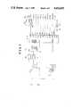
- FIG. 1is a circuit diagram showing the main part of the remote control adapter according to an embodiment of the present invention
- FIG. 2is a plan view of a conventional remote control box to be incorporated with the adapter shown in FIG. 1;
- FIG. 3is a perspective view showing a total system wherein the remote control adapter of FIG. 1 is being used.
- reference symbols L1 and L2denote telephone lines, respectively; and LT, a line transformer.
- Reference numeral 1denotes a line monitor circuit having both a ringing signal detection function and an on-hook detection function; 2, an amplifier for detecting a tone as a remote control signal sent from a pushphone of a calling party; and 3, a tone decoder for detecting the tone from the pushphone and converting it to a corresponding code signal.
- Reference symbol CPUdenotes a microprocessor (to be referred to as a CPU hereinafter) as a control means. In this embodiment, the CPU comprises, for example, a CPU 8748 available from Intel Corp., U.S.A.
- Reference symbols DB0 to DB3denote input ports, respectively; and P10 to P17 and P20 to P27, output ports, respectively.
- Reference numeral 5denotes a switching transistor, the base of which is connected to the output port P10.
- the collector and emitter of the transistor 5are respectively connected to terminals 21a and 21b of a 1CH (channel) selection pushbutton switch 21 on an infrared remote control box 4 of FIG. 2.
- the transistor 5is turned on in response to the output from the output port P10, so that the terminal 21a is electrically connected to the terminal 21b.
- An infrared generator (not shown) in the remote control box 4is connected to the terminals 21a and 21b of the 1CH selection button switch 21 through lead wires 4a and 4b.
- the infrared generatorWhen the transistor 5 is turned on to operate the pushbutton switch 21, the infrared generator is started, so that a coded 1CH selection infrared ray is emitted from an infrared emission surface 20.
- switching transistorsare respectively arranged between both terminals of each of switches 22 to 32 for other channels and switches 33 to 37 for PLAY, FF (fast forward), REW (rewind), STOP and REC (record) pushbutton switches of a video tape recorder (to be referred to as a VCR hereinafter) as electric equipment.
- the terminals of the switches 22 to 37are connected to the infrared generator.
- the switching transistors(only one transistor 5 is illustrated) are electrically connected to the pushbutton switches at contacts 21a' and 21b', (FIG. 1) by inserting the remote control box 4 into the remote control adapter 6 incorporating the line monitor circuit 1 and the microprocessor CPU, as shown in FIG. 3.
- TEL-1denotes a calling party's telephone set
- TEL-2a telephone set connected to the remote control adapter 6 of this embodiment.
- Reference numeral 16denotes a driver.
- Reference symbol Y-1denotes a looping relay with a contact y1-1.
- Reference numeral 17denotes a plug jack inserted in an earphone jack of the VCR. The plug jack 17 is connected to the secondary coil of the line transformer LT through an amplifier 18 so as to allow the calling party to monitor a voice signal in the REC or PLAY mode of the VCR.
- the operation of the remote control adapter 6 having the arrangement described abovewill be described hereinafter.
- the user or ownerinserts the remote control box 4 into the adapter 6 and faces the infrared emission surface of the remote control box 4 to a light-receiving portion 7 (FIG. 3) of the VCR before he leaves home.
- the ownercalls the remote control adapter 6 from an external pay telephone (pushphone).
- the ringing signalis supplied to a test terminal TEST1 of the CPU through the line monitor circuit 1, the output port P27 is set at logic "1" in accordance with the program prestored in the CPU.
- the elements 1 and 16, the CPU and the relay Y-1 as an engaging meansare held operative through the driver 16.
- the control program for this operationis known to those skilled in the art and a description thereof will be omitted.
- the telephone linesare engaged with the remote control adapter 6 through the contact y1-1 of the relay Y-1, thereby interrupting the ringing signal.
- the infrared emission surface 2 of the accessory remote control box 4 of the VCRemits the coded infrared ray to select the 1CH (Channel 1).
- the coded infrared rayis received by the light-receiving portion 7 of the VCR, so that the VCR is set in the 1CH operation mode.
- the audio signal in the 1CHis sent onto the telephone lines through the plug 17 inserted in the earphone jack of the VCR, the amplifier 18 and the line transformer LT. Therefore, the calling party (i.e., the owner) can confirm that he selects the right channel.
- the output from the output port P10is reset to logic "0" within 1 to 2 seconds in accordance with the control program.
- a tone signal therefromis decoded by the tone decoder 3.
- the code signal corresponding to the tone signalcauses the output port P17 of the CPU to be set at logic "1".
- the switching transistor(not shown) is connected to an REC button 37 of the remote control box 4 of FIG. 2. Therefore, the VCR starts recording for 1CH.
- the control program of the CPUis given such that predetermined pushbuttons (e.g., 1 and 0) are sequentially depressed within a predetermined period of time (1 to 2 seconds) for a two-digit channel (e.g., 10CH), that the "#" button is depressed once to stop the VCR, and that the REW and PLAY modes are set upon depression of the "#" button twice and three times, respectively.
- predetermined pushbuttonse.g., 1 and 0
- a two-digit channele.g. 10CH
- the remote control box 4 used as a separate unit in the conventional apparatuscan be plugged into the remote control adapter 6.
- the connectors at the coupling portions of the remote control box 4 and the remote control adapter 6must have a structure suitable for frequent detachment/attachment.
- One end of the remote control box 4has a female or male structure 40, and the corresponding adapter side has a male or female structure 41.
- the remote control box 4is detached from the remote control adapter 6 and is used in a conventional manner.
- the useris going out, he simply couples the remote control box 4 to the remote control adapter 6. Then, he can call the telephone set TEL-2 from the telephone set TEL-1 and arbitrarily control at the telephone set TEL-1 the television set or the VCR connected to the telephone set TEL-2.
- the above embodimentexemplifies the case wherein the accessory remote control box of the VCR is remote controlled from a pushphone to selectively perform REC, PLAY, STOP, REW and so on of the VCR for each channel.
- the present inventionis not limited to the remote control adapter for the VCR, but can be extended to other remote control adapters for equivalent equipment.
Landscapes
- Engineering & Computer Science (AREA)
- Multimedia (AREA)
- Automation & Control Theory (AREA)
- Signal Processing (AREA)
- Selective Calling Equipment (AREA)
- Telephonic Communication Services (AREA)
Abstract
Description
Claims (8)
Applications Claiming Priority (2)
| Application Number | Priority Date | Filing Date | Title |
|---|---|---|---|
| JP59222592AJPS61104351A (en) | 1984-10-23 | 1984-10-23 | Vtr remote control device by telephone line |
| JP59-222592 | 1984-10-23 |
Publications (1)
| Publication Number | Publication Date |
|---|---|
| US4656655Atrue US4656655A (en) | 1987-04-07 |
Family
ID=16784881
Family Applications (1)
| Application Number | Title | Priority Date | Filing Date |
|---|---|---|---|
| US06/790,647Expired - LifetimeUS4656655A (en) | 1984-10-23 | 1985-10-23 | Remote control adapter of electric equipment using telephone lines |
Country Status (3)
| Country | Link |
|---|---|
| US (1) | US4656655A (en) |
| JP (1) | JPS61104351A (en) |
| GB (1) | GB2166322B (en) |
Cited By (39)
| Publication number | Priority date | Publication date | Assignee | Title |
|---|---|---|---|---|
| US4885803A (en)* | 1987-03-17 | 1989-12-05 | Lawrence W. Hermann | System and method for controlling a plurality of electronic entertainment devices |
| US4885766A (en)* | 1986-01-31 | 1989-12-05 | Sharp Kabushiki Kaisha | Remote control device using a telephone line |
| US4899369A (en)* | 1989-05-05 | 1990-02-06 | Nynex | Radio-analogue method of audio presentation and control for audiotex services |
| US4910764A (en)* | 1989-04-13 | 1990-03-20 | Product Engineering & Manufacturing, Inc. | Facsimile and voice communications interface device |
| US4918439A (en)* | 1987-06-23 | 1990-04-17 | Cl 9, Inc. | Remote control device |
| USRE33369E (en)* | 1982-06-05 | 1990-10-02 | Hashimoto Corporation | Remote control device using telephone circuit of electric apparatus |
| US5227780A (en)* | 1989-03-16 | 1993-07-13 | Houston Satellite Systems, Inc. | Apparatus with a portable UHF radio transmitter remote for controlling one or more of infrared controlled appliances |
| GB2272600A (en)* | 1992-11-12 | 1994-05-18 | Alastair Gordon Fraser | Programming a recording apparatus over a telecommunication system |
| FR2708164A1 (en)* | 1993-07-23 | 1995-01-27 | Thomson Consumer Electronics | Downloading method for programming a radio frequency receiver. |
| US5414761A (en)* | 1987-10-14 | 1995-05-09 | Universal Electronics Inc. | Remote control system |
| US5420913A (en)* | 1992-05-01 | 1995-05-30 | Hashimoto Corporation | Device for making videotape recording reservations over a telephone line |
| US5548635A (en)* | 1994-01-21 | 1996-08-20 | Sasktel | System for controlling equipment within a telephone subscriber's premises using DTMF telephone tones |
| US6192236B1 (en) | 1997-05-08 | 2001-02-20 | Ericsson Inc. | Apparatus and methods for remote control of accessory devices using a radiotelephone as a receiver |
| US6215863B1 (en) | 1997-12-29 | 2001-04-10 | Ameritech Corporation | Method and apparatus for providing a station set with advanced telecommunications services |
| US6587067B2 (en) | 1987-10-14 | 2003-07-01 | Universal Electronics Inc. | Universal remote control with macro command capabilities |
| US20040125819A1 (en)* | 2001-07-05 | 2004-07-01 | Yehuda Binder | Telephone outlet with packet telephony adapter, and a network using same |
| US20040246165A1 (en)* | 2001-03-14 | 2004-12-09 | Universal Electronics Inc. | System and method for controlling home appliances |
| US20050249245A1 (en)* | 2004-05-06 | 2005-11-10 | Serconet Ltd. | System and method for carrying a wireless based signal over wiring |
| US20050277328A1 (en)* | 2000-04-19 | 2005-12-15 | Serconet Ltd | Network combining wired and non-wired segments |
| US20060197428A1 (en)* | 2005-02-21 | 2006-09-07 | Takeshi Tonegawa | Electron devices with non-evaporation-type getters and method for manufacturing the same |
| US20060220830A1 (en)* | 1997-12-29 | 2006-10-05 | Bennett Raymond Walden Iii | System and method for home automation and security |
| US20070173202A1 (en)* | 2006-01-11 | 2007-07-26 | Serconet Ltd. | Apparatus and method for frequency shifting of a wireless signal and systems using frequency shifting |
| US7274688B2 (en) | 2000-04-18 | 2007-09-25 | Serconet Ltd. | Telephone communication system over a single telephone line |
| US7317793B2 (en) | 2003-01-30 | 2008-01-08 | Serconet Ltd | Method and system for providing DC power on local telephone lines |
| US20080074258A1 (en)* | 1998-06-12 | 2008-03-27 | Bennett Raymond W Iii | Home gateway system for home automation and security |
| US7436842B2 (en) | 2001-10-11 | 2008-10-14 | Serconet Ltd. | Outlet with analog signal adapter, a method for use thereof and a network using said outlet |
| US7483524B2 (en) | 1999-07-20 | 2009-01-27 | Serconet, Ltd | Network for telephony and data communication |
| US7522714B2 (en) | 2000-03-20 | 2009-04-21 | Serconet Ltd. | Telephone outlet for implementing a local area network over telephone lines and a local area network using such outlets |
| US7686653B2 (en) | 2003-09-07 | 2010-03-30 | Mosaid Technologies Incorporated | Modular outlet |
| US20100309931A1 (en)* | 2007-10-22 | 2010-12-09 | Mobileaccess Networks Ltd. | Communication system using low bandwidth wires |
| US7873058B2 (en) | 2004-11-08 | 2011-01-18 | Mosaid Technologies Incorporated | Outlet with analog signal adapter, a method for use thereof and a network using said outlet |
| US20110170476A1 (en)* | 2009-02-08 | 2011-07-14 | Mobileaccess Networks Ltd. | Communication system using cables carrying ethernet signals |
| US8175649B2 (en) | 2008-06-20 | 2012-05-08 | Corning Mobileaccess Ltd | Method and system for real time control of an active antenna over a distributed antenna system |
| US8238328B2 (en) | 2003-03-13 | 2012-08-07 | Mosaid Technologies Incorporated | Telephone system having multiple distinct sources and accessories therefor |
| US8270430B2 (en) | 1998-07-28 | 2012-09-18 | Mosaid Technologies Incorporated | Local area network of serial intelligent cells |
| US20150221302A1 (en)* | 2014-02-06 | 2015-08-06 | Samsung Electronics Co., Ltd. | Display apparatus and method for controlling electronic apparatus using the same |
| US9184960B1 (en) | 2014-09-25 | 2015-11-10 | Corning Optical Communications Wireless Ltd | Frequency shifting a communications signal(s) in a multi-frequency distributed antenna system (DAS) to avoid or reduce frequency interference |
| US9338823B2 (en) | 2012-03-23 | 2016-05-10 | Corning Optical Communications Wireless Ltd | Radio-frequency integrated circuit (RFIC) chip(s) for providing distributed antenna system functionalities, and related components, systems, and methods |
| US10986165B2 (en) | 2004-01-13 | 2021-04-20 | May Patents Ltd. | Information device |
Families Citing this family (19)
| Publication number | Priority date | Publication date | Assignee | Title |
|---|---|---|---|---|
| GB8524665D0 (en)* | 1985-10-07 | 1985-11-13 | Emi Plc Thorn | Display system |
| JPS62278866A (en)* | 1986-05-27 | 1987-12-03 | Sharp Corp | Remote controller |
| FR2597240A1 (en)* | 1986-04-11 | 1987-10-16 | Brulfert Bernard | Device for remote vocal control by speech synthesis over a telephone link |
| DE3850014T2 (en)* | 1987-03-31 | 1994-09-15 | Honda Motor Co Ltd | DEVICE RESPECTING TO RADIO SIGNALS FOR CONTROLLING A MOVABLE DEVICE. |
| DE3819863A1 (en)* | 1987-06-12 | 1989-01-05 | Matsushita Electric Industrial Co Ltd | REMOTE CONTROL DEVICE FOR ELECTRONIC DEVICES |
| US4841562A (en)* | 1987-07-24 | 1989-06-20 | Steven Lem | Telephone VCR control |
| US5228077A (en)* | 1987-12-02 | 1993-07-13 | Universal Electronics Inc. | Remotely upgradable universal remote control |
| US4959810A (en)* | 1987-10-14 | 1990-09-25 | Universal Electronics, Inc. | Universal remote control device |
| US4882747A (en)* | 1988-05-12 | 1989-11-21 | Jerry Williams | Infrared communication apparatus for remote site applications |
| IT1228604B (en)* | 1989-01-10 | 1991-06-24 | Aton S R L | EQUIPMENT FOR REMOTE TELEPHONE ACTIVATION OF HEATING AND / OR ENVIRONMENTAL CONDITIONING IN GENERAL, AND THERMOREGULATOR DEVICE USED IN THIS EQUIPMENT. |
| US5844596A (en) | 1989-07-14 | 1998-12-01 | Inline Connection Corporation | Two-way RF communication at points of convergence of wire pairs from separate internal telephone networks |
| US5929896A (en)* | 1989-07-14 | 1999-07-27 | Inline Connection Corporation | RF broadcast system utilizing internal telephone lines |
| US5010399A (en) | 1989-07-14 | 1991-04-23 | Inline Connection Corporation | Video transmission and control system utilizing internal telephone lines |
| US6243446B1 (en) | 1997-03-11 | 2001-06-05 | Inline Connections Corporation | Distributed splitter for data transmission over twisted wire pairs |
| FR2661304B1 (en)* | 1990-04-24 | 1996-09-13 | Andre Billmann | RECORDING OF A TELEVISION PROGRAM SEQUENCE AT THE PRECISE TIME OF ITS BEGINNING. |
| GB2258583A (en)* | 1991-08-06 | 1993-02-10 | Gec Ferranti Defence Syst | Video recorder remote control |
| US6192399B1 (en) | 1997-07-11 | 2001-02-20 | Inline Connections Corporation | Twisted pair communication system |
| US6532279B1 (en) | 1999-06-11 | 2003-03-11 | David D. Goodman | High-speed data communication over a residential telephone wiring network |
| GB2389002A (en)* | 2002-05-23 | 2003-11-26 | Thomas Edmund Coster | Door answering service |
Citations (5)
| Publication number | Priority date | Publication date | Assignee | Title |
|---|---|---|---|---|
| US4121053A (en)* | 1977-05-05 | 1978-10-17 | Dick William J | Telephone command apparatus |
| US4442319A (en)* | 1981-02-26 | 1984-04-10 | Treidl Bernhard L | Telephone accessible appliance control system |
| US4467144A (en)* | 1982-04-08 | 1984-08-21 | Amf Incorporated | Telephone annuciator extender |
| US4491690A (en)* | 1983-02-22 | 1985-01-01 | Daley Ronald J | Remote control system for use with a telephone |
| US4540851A (en)* | 1982-06-05 | 1985-09-10 | Hashimoto Corporation | Remote control device using telephone circuit of electric apparatus |
- 1984
- 1984-10-23JPJP59222592Apatent/JPS61104351A/enactiveGranted
- 1985
- 1985-10-23USUS06/790,647patent/US4656655A/ennot_activeExpired - Lifetime
- 1985-10-23GBGB08526166Apatent/GB2166322B/ennot_activeExpired
Patent Citations (5)
| Publication number | Priority date | Publication date | Assignee | Title |
|---|---|---|---|---|
| US4121053A (en)* | 1977-05-05 | 1978-10-17 | Dick William J | Telephone command apparatus |
| US4442319A (en)* | 1981-02-26 | 1984-04-10 | Treidl Bernhard L | Telephone accessible appliance control system |
| US4467144A (en)* | 1982-04-08 | 1984-08-21 | Amf Incorporated | Telephone annuciator extender |
| US4540851A (en)* | 1982-06-05 | 1985-09-10 | Hashimoto Corporation | Remote control device using telephone circuit of electric apparatus |
| US4491690A (en)* | 1983-02-22 | 1985-01-01 | Daley Ronald J | Remote control system for use with a telephone |
Non-Patent Citations (2)
| Title |
|---|
| "An Interactive Video Information Terminal" by Gordon IEEE Transactions on Communications vol. Com-31, No. 2, Feb. 1983. |
| An Interactive Video Information Terminal by Gordon IEEE Transactions on Communications vol. Com 31, No. 2, Feb. 1983.* |
Cited By (106)
| Publication number | Priority date | Publication date | Assignee | Title |
|---|---|---|---|---|
| USRE33369E (en)* | 1982-06-05 | 1990-10-02 | Hashimoto Corporation | Remote control device using telephone circuit of electric apparatus |
| US4885766A (en)* | 1986-01-31 | 1989-12-05 | Sharp Kabushiki Kaisha | Remote control device using a telephone line |
| US4885803A (en)* | 1987-03-17 | 1989-12-05 | Lawrence W. Hermann | System and method for controlling a plurality of electronic entertainment devices |
| US4918439A (en)* | 1987-06-23 | 1990-04-17 | Cl 9, Inc. | Remote control device |
| US6587067B2 (en) | 1987-10-14 | 2003-07-01 | Universal Electronics Inc. | Universal remote control with macro command capabilities |
| US5414761A (en)* | 1987-10-14 | 1995-05-09 | Universal Electronics Inc. | Remote control system |
| US5227780A (en)* | 1989-03-16 | 1993-07-13 | Houston Satellite Systems, Inc. | Apparatus with a portable UHF radio transmitter remote for controlling one or more of infrared controlled appliances |
| US4910764A (en)* | 1989-04-13 | 1990-03-20 | Product Engineering & Manufacturing, Inc. | Facsimile and voice communications interface device |
| US4899369A (en)* | 1989-05-05 | 1990-02-06 | Nynex | Radio-analogue method of audio presentation and control for audiotex services |
| US5420913A (en)* | 1992-05-01 | 1995-05-30 | Hashimoto Corporation | Device for making videotape recording reservations over a telephone line |
| GB2272600A (en)* | 1992-11-12 | 1994-05-18 | Alastair Gordon Fraser | Programming a recording apparatus over a telecommunication system |
| FR2708164A1 (en)* | 1993-07-23 | 1995-01-27 | Thomson Consumer Electronics | Downloading method for programming a radio frequency receiver. |
| US5548635A (en)* | 1994-01-21 | 1996-08-20 | Sasktel | System for controlling equipment within a telephone subscriber's premises using DTMF telephone tones |
| US6192236B1 (en) | 1997-05-08 | 2001-02-20 | Ericsson Inc. | Apparatus and methods for remote control of accessory devices using a radiotelephone as a receiver |
| US6215863B1 (en) | 1997-12-29 | 2001-04-10 | Ameritech Corporation | Method and apparatus for providing a station set with advanced telecommunications services |
| US9355538B2 (en) | 1997-12-29 | 2016-05-31 | At&T Intellectual Property I, L.P. | System and method for home automation and security |
| US9143342B2 (en) | 1997-12-29 | 2015-09-22 | At&T Intellectual Property I, L.P. | System and method for home automation and security |
| US8922361B2 (en) | 1997-12-29 | 2014-12-30 | At&T Intellectual Property I, L.P. | System and method for home automation and security |
| US8063761B2 (en) | 1997-12-29 | 2011-11-22 | At&T Intellectual Property I, L.P. | System and method for home automation and security |
| US20090195352A1 (en)* | 1997-12-29 | 2009-08-06 | Bennett Raymond Walden Iii | System and method for home automation and security |
| US20060220830A1 (en)* | 1997-12-29 | 2006-10-05 | Bennett Raymond Walden Iii | System and method for home automation and security |
| US7551071B2 (en) | 1997-12-29 | 2009-06-23 | At&T Intellectual Property I, L.P. | System and method for home automation and security |
| US8242900B2 (en) | 1997-12-29 | 2012-08-14 | At&T Intellectual Property I, L.P. | System and method for home automation and security |
| US7912447B2 (en) | 1998-06-12 | 2011-03-22 | At&T Intellectual Property I, L.P. | Home gateway system for home automation and security |
| US20080074258A1 (en)* | 1998-06-12 | 2008-03-27 | Bennett Raymond W Iii | Home gateway system for home automation and security |
| US8885660B2 (en) | 1998-07-28 | 2014-11-11 | Conversant Intellectual Property Management Incorporated | Local area network of serial intelligent cells |
| US8867523B2 (en) | 1998-07-28 | 2014-10-21 | Conversant Intellectual Property Management Incorporated | Local area network of serial intelligent cells |
| US8908673B2 (en) | 1998-07-28 | 2014-12-09 | Conversant Intellectual Property Management Incorporated | Local area network of serial intelligent cells |
| US8885659B2 (en) | 1998-07-28 | 2014-11-11 | Conversant Intellectual Property Management Incorporated | Local area network of serial intelligent cells |
| US8325636B2 (en) | 1998-07-28 | 2012-12-04 | Mosaid Technologies Incorporated | Local area network of serial intelligent cells |
| US8270430B2 (en) | 1998-07-28 | 2012-09-18 | Mosaid Technologies Incorporated | Local area network of serial intelligent cells |
| US7483524B2 (en) | 1999-07-20 | 2009-01-27 | Serconet, Ltd | Network for telephony and data communication |
| US7492875B2 (en) | 1999-07-20 | 2009-02-17 | Serconet, Ltd. | Network for telephony and data communication |
| US7522713B2 (en) | 1999-07-20 | 2009-04-21 | Serconet, Ltd. | Network for telephony and data communication |
| US8351582B2 (en) | 1999-07-20 | 2013-01-08 | Mosaid Technologies Incorporated | Network for telephony and data communication |
| US8929523B2 (en) | 1999-07-20 | 2015-01-06 | Conversant Intellectual Property Management Inc. | Network for telephony and data communication |
| US7522714B2 (en) | 2000-03-20 | 2009-04-21 | Serconet Ltd. | Telephone outlet for implementing a local area network over telephone lines and a local area network using such outlets |
| US8855277B2 (en) | 2000-03-20 | 2014-10-07 | Conversant Intellectual Property Managment Incorporated | Telephone outlet for implementing a local area network over telephone lines and a local area network using such outlets |
| US7715534B2 (en) | 2000-03-20 | 2010-05-11 | Mosaid Technologies Incorporated | Telephone outlet for implementing a local area network over telephone lines and a local area network using such outlets |
| US8363797B2 (en) | 2000-03-20 | 2013-01-29 | Mosaid Technologies Incorporated | Telephone outlet for implementing a local area network over telephone lines and a local area network using such outlets |
| US20080043646A1 (en)* | 2000-04-18 | 2008-02-21 | Serconet Ltd. | Telephone communication system over a single telephone line |
| US7466722B2 (en) | 2000-04-18 | 2008-12-16 | Serconet Ltd | Telephone communication system over a single telephone line |
| US8000349B2 (en) | 2000-04-18 | 2011-08-16 | Mosaid Technologies Incorporated | Telephone communication system over a single telephone line |
| US8559422B2 (en) | 2000-04-18 | 2013-10-15 | Mosaid Technologies Incorporated | Telephone communication system over a single telephone line |
| US8223800B2 (en) | 2000-04-18 | 2012-07-17 | Mosaid Technologies Incorporated | Telephone communication system over a single telephone line |
| US7397791B2 (en) | 2000-04-18 | 2008-07-08 | Serconet, Ltd. | Telephone communication system over a single telephone line |
| US7593394B2 (en) | 2000-04-18 | 2009-09-22 | Mosaid Technologies Incorporated | Telephone communication system over a single telephone line |
| US7274688B2 (en) | 2000-04-18 | 2007-09-25 | Serconet Ltd. | Telephone communication system over a single telephone line |
| US8982904B2 (en) | 2000-04-19 | 2015-03-17 | Conversant Intellectual Property Management Inc. | Network combining wired and non-wired segments |
| US8873586B2 (en) | 2000-04-19 | 2014-10-28 | Conversant Intellectual Property Management Incorporated | Network combining wired and non-wired segments |
| US8982903B2 (en) | 2000-04-19 | 2015-03-17 | Conversant Intellectual Property Management Inc. | Network combining wired and non-wired segments |
| US8867506B2 (en) | 2000-04-19 | 2014-10-21 | Conversant Intellectual Property Management Incorporated | Network combining wired and non-wired segments |
| US7633966B2 (en) | 2000-04-19 | 2009-12-15 | Mosaid Technologies Incorporated | Network combining wired and non-wired segments |
| US20050277328A1 (en)* | 2000-04-19 | 2005-12-15 | Serconet Ltd | Network combining wired and non-wired segments |
| US8848725B2 (en) | 2000-04-19 | 2014-09-30 | Conversant Intellectual Property Management Incorporated | Network combining wired and non-wired segments |
| US8873575B2 (en) | 2000-04-19 | 2014-10-28 | Conversant Intellectual Property Management Incorporated | Network combining wired and non-wired segments |
| US20040246165A1 (en)* | 2001-03-14 | 2004-12-09 | Universal Electronics Inc. | System and method for controlling home appliances |
| US6980150B2 (en)* | 2001-03-14 | 2005-12-27 | Universal Electronics Inc. | System and method for controlling home appliances |
| US7680255B2 (en) | 2001-07-05 | 2010-03-16 | Mosaid Technologies Incorporated | Telephone outlet with packet telephony adaptor, and a network using same |
| US7542554B2 (en) | 2001-07-05 | 2009-06-02 | Serconet, Ltd | Telephone outlet with packet telephony adapter, and a network using same |
| US8761186B2 (en) | 2001-07-05 | 2014-06-24 | Conversant Intellectual Property Management Incorporated | Telephone outlet with packet telephony adapter, and a network using same |
| US20040125819A1 (en)* | 2001-07-05 | 2004-07-01 | Yehuda Binder | Telephone outlet with packet telephony adapter, and a network using same |
| US8472593B2 (en) | 2001-07-05 | 2013-06-25 | Mosaid Technologies Incorporated | Telephone outlet with packet telephony adaptor, and a network using same |
| US7769030B2 (en) | 2001-07-05 | 2010-08-03 | Mosaid Technologies Incorporated | Telephone outlet with packet telephony adapter, and a network using same |
| US7453895B2 (en) | 2001-10-11 | 2008-11-18 | Serconet Ltd | Outlet with analog signal adapter, a method for use thereof and a network using said outlet |
| US7860084B2 (en) | 2001-10-11 | 2010-12-28 | Mosaid Technologies Incorporated | Outlet with analog signal adapter, a method for use thereof and a network using said outlet |
| US7436842B2 (en) | 2001-10-11 | 2008-10-14 | Serconet Ltd. | Outlet with analog signal adapter, a method for use thereof and a network using said outlet |
| US7889720B2 (en) | 2001-10-11 | 2011-02-15 | Mosaid Technologies Incorporated | Outlet with analog signal adapter, a method for use thereof and a network using said outlet |
| US7953071B2 (en) | 2001-10-11 | 2011-05-31 | Mosaid Technologies Incorporated | Outlet with analog signal adapter, a method for use thereof and a network using said outlet |
| US8107618B2 (en) | 2003-01-30 | 2012-01-31 | Mosaid Technologies Incorporated | Method and system for providing DC power on local telephone lines |
| US7317793B2 (en) | 2003-01-30 | 2008-01-08 | Serconet Ltd | Method and system for providing DC power on local telephone lines |
| US7702095B2 (en) | 2003-01-30 | 2010-04-20 | Mosaid Technologies Incorporated | Method and system for providing DC power on local telephone lines |
| US8787562B2 (en) | 2003-01-30 | 2014-07-22 | Conversant Intellectual Property Management Inc. | Method and system for providing DC power on local telephone lines |
| US8238328B2 (en) | 2003-03-13 | 2012-08-07 | Mosaid Technologies Incorporated | Telephone system having multiple distinct sources and accessories therefor |
| US7867035B2 (en) | 2003-07-09 | 2011-01-11 | Mosaid Technologies Incorporated | Modular outlet |
| US8092258B2 (en) | 2003-09-07 | 2012-01-10 | Mosaid Technologies Incorporated | Modular outlet |
| US8360810B2 (en) | 2003-09-07 | 2013-01-29 | Mosaid Technologies Incorporated | Modular outlet |
| US7686653B2 (en) | 2003-09-07 | 2010-03-30 | Mosaid Technologies Incorporated | Modular outlet |
| US8235755B2 (en) | 2003-09-07 | 2012-08-07 | Mosaid Technologies Incorporated | Modular outlet |
| US8591264B2 (en) | 2003-09-07 | 2013-11-26 | Mosaid Technologies Incorporated | Modular outlet |
| US10986164B2 (en) | 2004-01-13 | 2021-04-20 | May Patents Ltd. | Information device |
| US11095708B2 (en) | 2004-01-13 | 2021-08-17 | May Patents Ltd. | Information device |
| US11032353B2 (en) | 2004-01-13 | 2021-06-08 | May Patents Ltd. | Information device |
| US10986165B2 (en) | 2004-01-13 | 2021-04-20 | May Patents Ltd. | Information device |
| US20050249245A1 (en)* | 2004-05-06 | 2005-11-10 | Serconet Ltd. | System and method for carrying a wireless based signal over wiring |
| US8325759B2 (en) | 2004-05-06 | 2012-12-04 | Corning Mobileaccess Ltd | System and method for carrying a wireless based signal over wiring |
| US7873058B2 (en) | 2004-11-08 | 2011-01-18 | Mosaid Technologies Incorporated | Outlet with analog signal adapter, a method for use thereof and a network using said outlet |
| US20060197428A1 (en)* | 2005-02-21 | 2006-09-07 | Takeshi Tonegawa | Electron devices with non-evaporation-type getters and method for manufacturing the same |
| US7587001B2 (en) | 2006-01-11 | 2009-09-08 | Serconet Ltd. | Apparatus and method for frequency shifting of a wireless signal and systems using frequency shifting |
| US20070173202A1 (en)* | 2006-01-11 | 2007-07-26 | Serconet Ltd. | Apparatus and method for frequency shifting of a wireless signal and systems using frequency shifting |
| US7813451B2 (en) | 2006-01-11 | 2010-10-12 | Mobileaccess Networks Ltd. | Apparatus and method for frequency shifting of a wireless signal and systems using frequency shifting |
| US8184681B2 (en) | 2006-01-11 | 2012-05-22 | Corning Mobileaccess Ltd | Apparatus and method for frequency shifting of a wireless signal and systems using frequency shifting |
| US20100309931A1 (en)* | 2007-10-22 | 2010-12-09 | Mobileaccess Networks Ltd. | Communication system using low bandwidth wires |
| US8594133B2 (en) | 2007-10-22 | 2013-11-26 | Corning Mobileaccess Ltd. | Communication system using low bandwidth wires |
| US9813229B2 (en) | 2007-10-22 | 2017-11-07 | Corning Optical Communications Wireless Ltd | Communication system using low bandwidth wires |
| US9549301B2 (en) | 2007-12-17 | 2017-01-17 | Corning Optical Communications Wireless Ltd | Method and system for real time control of an active antenna over a distributed antenna system |
| US8175649B2 (en) | 2008-06-20 | 2012-05-08 | Corning Mobileaccess Ltd | Method and system for real time control of an active antenna over a distributed antenna system |
| US20110170476A1 (en)* | 2009-02-08 | 2011-07-14 | Mobileaccess Networks Ltd. | Communication system using cables carrying ethernet signals |
| US8897215B2 (en) | 2009-02-08 | 2014-11-25 | Corning Optical Communications Wireless Ltd | Communication system using cables carrying ethernet signals |
| US9948329B2 (en) | 2012-03-23 | 2018-04-17 | Corning Optical Communications Wireless, LTD | Radio-frequency integrated circuit (RFIC) chip(s) for providing distributed antenna system functionalities, and related components, systems, and methods |
| US10141959B2 (en) | 2012-03-23 | 2018-11-27 | Corning Optical Communications Wireless Ltd | Radio-frequency integrated circuit (RFIC) chip(s) for providing distributed antenna system functionalities, and related components, systems, and methods |
| US9338823B2 (en) | 2012-03-23 | 2016-05-10 | Corning Optical Communications Wireless Ltd | Radio-frequency integrated circuit (RFIC) chip(s) for providing distributed antenna system functionalities, and related components, systems, and methods |
| US20150221302A1 (en)* | 2014-02-06 | 2015-08-06 | Samsung Electronics Co., Ltd. | Display apparatus and method for controlling electronic apparatus using the same |
| US9515855B2 (en) | 2014-09-25 | 2016-12-06 | Corning Optical Communications Wireless Ltd | Frequency shifting a communications signal(s) in a multi-frequency distributed antenna system (DAS) to avoid or reduce frequency interference |
| US9184960B1 (en) | 2014-09-25 | 2015-11-10 | Corning Optical Communications Wireless Ltd | Frequency shifting a communications signal(s) in a multi-frequency distributed antenna system (DAS) to avoid or reduce frequency interference |
| US9253003B1 (en) | 2014-09-25 | 2016-02-02 | Corning Optical Communications Wireless Ltd | Frequency shifting a communications signal(S) in a multi-frequency distributed antenna system (DAS) to avoid or reduce frequency interference |
Also Published As
| Publication number | Publication date |
|---|---|
| JPH0412529B2 (en) | 1992-03-04 |
| GB8526166D0 (en) | 1985-11-27 |
| JPS61104351A (en) | 1986-05-22 |
| GB2166322A (en) | 1986-04-30 |
| GB2166322B (en) | 1988-08-17 |
Similar Documents
| Publication | Publication Date | Title |
|---|---|---|
| US4656655A (en) | Remote control adapter of electric equipment using telephone lines | |
| US6445933B1 (en) | Tele-remote telephone and remote control device | |
| US5420913A (en) | Device for making videotape recording reservations over a telephone line | |
| US5220594A (en) | Cordless telephone system having a telephone answering machine function | |
| US4788714A (en) | Remote controlling telephone unit for selectively activating one of a plurality of devices | |
| US4540851A (en) | Remote control device using telephone circuit of electric apparatus | |
| EP0378846A2 (en) | Telephone apparatus | |
| EP0284401B1 (en) | Telephone equipment with multiple function | |
| US4829555A (en) | TAD incorporated with VCR | |
| US5337343A (en) | Headset bridge for operating multiple communication devices | |
| US4658097A (en) | Remote terminal for use with central dictation apparatus | |
| JPH0365067B2 (en) | ||
| US5721767A (en) | Video player with telephone interface to provide telephone answering and dialing functions with on-screen display | |
| JPH04276342A (en) | Remote control system for video tape recorder | |
| US5187734A (en) | Telephone message recording device | |
| US20020075161A1 (en) | Universal remote control system | |
| KR100405591B1 (en) | Internet phone exchanger with gateway feature | |
| JPH0718198Y2 (en) | Telephone with remote control | |
| JPH055732Y2 (en) | ||
| JPH1079801A (en) | Remote control home automation equipment | |
| JPH0466422B2 (en) | ||
| JP3049728B2 (en) | VTR | |
| JPH02305228A (en) | infrared remote control device | |
| JPS6221366A (en) | timer control device | |
| KR100263369B1 (en) | Television having function of voice information in channel using by telephone |
Legal Events
| Date | Code | Title | Description |
|---|---|---|---|
| AS | Assignment | Owner name:HASHIMOTO CORPORATION, 28-2, KOMAZAWA 2-CHOME, SET Free format text:ASSIGNMENT OF ASSIGNORS INTEREST.;ASSIGNOR:HASHIMOTO, KAZUO;REEL/FRAME:004472/0169 Effective date:19850925 | |
| STCF | Information on status: patent grant | Free format text:PATENTED CASE | |
| FEPP | Fee payment procedure | Free format text:PAYOR NUMBER ASSIGNED (ORIGINAL EVENT CODE: ASPN); ENTITY STATUS OF PATENT OWNER: LARGE ENTITY | |
| FPAY | Fee payment | Year of fee payment:4 | |
| FPAY | Fee payment | Year of fee payment:8 | |
| FEPP | Fee payment procedure | Free format text:PAT HLDR NO LONGER CLAIMS SMALL ENT STAT AS INDIV INVENTOR (ORIGINAL EVENT CODE: LSM1); ENTITY STATUS OF PATENT OWNER: LARGE ENTITY Free format text:PAYER NUMBER DE-ASSIGNED (ORIGINAL EVENT CODE: RMPN); ENTITY STATUS OF PATENT OWNER: LARGE ENTITY Free format text:PAYOR NUMBER ASSIGNED (ORIGINAL EVENT CODE: ASPN); ENTITY STATUS OF PATENT OWNER: LARGE ENTITY | |
| REFU | Refund | Free format text:REFUND - PAYMENT OF MAINTENANCE FEE, 12TH YR, SMALL ENTITY (ORIGINAL EVENT CODE: R285); ENTITY STATUS OF PATENT OWNER: LARGE ENTITY | |
| AS | Assignment | Owner name:PHONETEL COMMUNICATIONS, INC., TEXAS Free format text:ASSIGNMENT OF ASSIGNORS INTEREST;ASSIGNOR:HASHIMOTO CORPORATION;REEL/FRAME:008876/0861 Effective date:19971230 | |
| FPAY | Fee payment | Year of fee payment:12 | |
| AS | Assignment | Owner name:PHONETEL COMMUNICATIONS, INC., TEXAS Free format text:ASSIGNMENT OF ASSIGNORS INTEREST;ASSIGNOR:HASHIMOTO CORPORATION;REEL/FRAME:009414/0148 Effective date:19980817 | |
| AS | Assignment | Owner name:HASHIMOTO CORPORATION, JAPAN Free format text:ASSIGNMENT OF ASSIGNORS INTEREST;ASSIGNOR:PHONETEL COMMUNICATIONS, INC.;REEL/FRAME:016369/0134 Effective date:20030828 |