US4656586A - Automatic vehicle testing apparatus - Google Patents
Automatic vehicle testing apparatusDownload PDFInfo
- Publication number
- US4656586A US4656586AUS06/638,139US63813984AUS4656586AUS 4656586 AUS4656586 AUS 4656586AUS 63813984 AUS63813984 AUS 63813984AUS 4656586 AUS4656586 AUS 4656586A
- Authority
- US
- United States
- Prior art keywords
- vehicle
- control unit
- test
- unit
- central station
- Prior art date
- Legal status (The legal status is an assumption and is not a legal conclusion. Google has not performed a legal analysis and makes no representation as to the accuracy of the status listed.)
- Expired - Fee Related
Links
Images


Classifications
- G—PHYSICS
- G01—MEASURING; TESTING
- G01M—TESTING STATIC OR DYNAMIC BALANCE OF MACHINES OR STRUCTURES; TESTING OF STRUCTURES OR APPARATUS, NOT OTHERWISE PROVIDED FOR
- G01M17/00—Testing of vehicles
- B—PERFORMING OPERATIONS; TRANSPORTING
- B61—RAILWAYS
- B61L—GUIDING RAILWAY TRAFFIC; ENSURING THE SAFETY OF RAILWAY TRAFFIC
- B61L15/00—Indicators provided on the vehicle or train for signalling purposes
- B61L15/0018—Communication with or on the vehicle or train
- B61L15/0036—Conductor-based, e.g. using CAN-Bus, train-line or optical fibres
- B—PERFORMING OPERATIONS; TRANSPORTING
- B61—RAILWAYS
- B61L—GUIDING RAILWAY TRAFFIC; ENSURING THE SAFETY OF RAILWAY TRAFFIC
- B61L15/00—Indicators provided on the vehicle or train for signalling purposes
- B61L15/0081—On-board diagnosis or maintenance
Definitions
- the present inventionrelates to an apparatus for automatically testing vehicles.
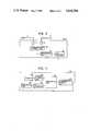
- FIG. 1is a diagram showing the arrangement of a conventional vehicle data transmitting system, such as may be applied to a railroad train.
- reference numeral 1designates a first vehicle having an operator's cab; 2 n through w 4 , second vehicles having no operator's cab, the first and second vehicles being connected to one another; 3, a central station mounted on the first vehicle for transmitting data; 4, terminal stations mounted on the second vehicles for receiving data from the central station 3; 5, optical transmission lines of optical fibers connecting the central station 3 and the terminal station 4 to one another; 6, control units mounted on the vehicles 1 and 2 n and connected to the central station 3 and the terminal stations 4, respectively, as shown in FIG. 1; 7, a control command unit connected to the central station 3; and 8, receptacles provided on the first and second vehicles 1 and 2 n and connected to the control units 6.
- a control command output by the control command unit 7is applied to the central station 3 and is then supplied through the transmission lines 5 to the terminal stations 4, and the control units 6 are operated by commands from the central station 3 and the respective terminal stations 4.
- FIG. 2In general, equipment mounted on the train is inspected with a test device as shown in FIG. 2, which is installed at a vehicle pool where trains are gathered.
- reference numeral 9designates a response signal generating unit; 10, a measuring unit, the units 9 and 10 forming a test executing unit 11; and 12, a plug connected to the test executing unit 11.
- the plug 12can be connected to the receptacles 8 of the vehicles 1 and 2 n .
- reference numeral 13designates a test controller connected to the test executing unit.
- the plug 12 of the test device shown in FIG. 2is connected to the receptacle 8 of a selected one of the vehicles so that the test executing unit 11 is connected to the control unit 6 of the vehicle.
- the test controller 13When so connected, the test controller 13 outputs a test command specifying a test item, and the response signal generating unit 9 supplies a response signal corresponding to the command to the control unit 6.
- the control unit 6is operated as required.
- the operation signal of the control unit 6is measured by the measuring unit 10, and the measurement signal is processed and recorded by the test controller 13.
- the methodis disadvantageous in that it takes a relatively long time to accomplish the test, and the received signal is affected by noise because the connecting line between the test executing unit 11 and the control unit 6 is relatively long; that is, it is impossible to automatically test the vehicles.
- An object of the inventionis to eliminate the above-described difficulties accompanying a conventional test device. More specifically, an object of the invention is to provide an automatic vehicle testing apparatus which allows the central station to operate in an automatic test mode, and in which a test controller installed at a test site is operated to cause the central station to operate in the automatic test mode, a response signal generating unit for operating a unit to be controlled and a monitoring unit for monitoring the operation thereof are connected to each terminal station and the respective unit to be controlled, and data provided in the automatic test mode is transmitted through the optical transmission lines.
- FIG. 1is an explanatory diagram showing the arrangement of a conventional vehicle data transmitting system
- FIG. 2is an explanatory diagram showing the arrangement of a conventional test device
- FIG. 3is an explanatory diagram showing the arrangement of a test device constructed according to the invention.
- FIG. 4is an explanatory diagram showing testing of vehicles using the arrangement of FIG. 3;
- FIG. 5is an explanatory diagram showing a second embodiment of the invention.
- FIG. 6is a detailed block diagram showing the structure of the central and terminal stations employed in the arrangement of FIG. 3;
- FIG. 7is a detailed block diagram showing the structure of a test controller employed in the arrangement of FIG. 3.
- FIG. 3is an explanatory diagram showing the arrangement of a preferred embodiment of an automatic vehicle testing apparatus of the invention.
- reference numerals 1, 2, 5, 6 and 7designate the same components as in FIG. 1 showing the conventional vehicle data transmitting system.
- reference numeral 14designates a central station connected to the control unit 6 and the control command unit 7, the central station 14 being operated in an automatic test mode when required; 15, terminal stations connected to the control units 6 and the central station 14; 16, a receptacle provided on the first vehicle 1 and connected to the central station 14; and 17, receptacles provided on the first and second vehicles 1 and 2 n , the receptacles 17 being connected to the central station 14, the terminal stations 15 and the control units 6.
- the central station 14 and the terminal stations 15are so designed that they transmit control data to their control units 6 only when they receive control commands from the respective control command unit 7.
- a control command output by the control command unit 7is applied through the central station 14 to the terminal stations 15 to operate the control units 6.
- a train having the data transmitting systemis sent to a vehicle pool provided with a test apparatus as shown in FIG. 4 where equipment on the vehicles is to be tested.
- reference numeral 18designates a test controller; 19, a plug connected to the test controller 18; 11, test executing units each having an associated signal generating unit 9 and a measuring unit 10 the same as the conventional test executing unit; and 20, plugs connected to respective ones of the test executing units 11. More specifically, each plug 20 is so connected to the respective test executing unit 11 that the associated signal generating unit 9 receives signals and the measuring unit 10 outputs signals.
- the control command unit 7is turned off and other necessary actions are taken to inhibit subsequent operation.
- the plugs 19 and 20are connected to the receptacles 16 and 17 of the vehicles 1 and 2 n , respectively, so that the central station 14 and the terminal stations 15 are connected to the test controller 18 and the test executing units 11.
- the central stationWhen, under this condition, test items and vehicles to be tested are specified for the test controller 18 and a test command is output, the central station, being placed in the automatic test mode, applies a test signal to the terminal stations 15 according to the test command, and the terminal stations 15 supply the test signal to the test executing units 11.
- the control units 6are operated by equivalent signals provided by the equivalent signal generating units 9 to apply operating signals to the measuring units 10.
- the measuring units 10process the operating signals to determine the appropriate operating conditions for the control units 6, and thereby apply the operating condition data to the respective terminal stations 15. This data is transmitted to the central station 14 and sent to the test controller 18. The data is displayed or recorded in the same manner for the test items in the test controller 18.
- the control unit 6 on the first vehicle 1, which is connected to the central station 14,is tested by the latter as in the case of the control units 6 of the second vehicles 2 n .
- FIG. 6shows in more detail the structure of the central and terminal stations employed in the arrangement of FIG. 3.
- a single optical fiber which forms the transmission lines 5is coupled through electrooptical couplers 31 to a transmission control unit 32, the latter being coupled to a processing unit 33.
- the processing unit 33communicates through an input/output interface 34 with the respective control units 6.
- the test controller 18includes an operating unit 46 communicating with a processing unit 42 via an input/output interface 44.
- the processing unit 42produces data for presentation on a display 45 and communicates this data via display control unit 43.
- Input and output between the processing unit 42 and the plug 19is via a transmission control unit 41.
- test executing units 11are provided on the vehicles 1 and 2 n so that the vehicles can be automatically tested merely by connecting the central station 14 to the test controller 18. Otherwise, this embodiment operates in the same manner as the first embodiment described above.
- the central stationcan be placed in an automatic test mode.
- the stationary test controlleris used to place the central station in the automatic test mode, the equivalent signal generating units for operating the units to be controlled and monitoring units for monitoring operations are connected between the terminal units and the units to be controlled, and the data in the automatic test mode is transmitted through the optical transmission lines to automatically test the vehicles.
Landscapes
- Engineering & Computer Science (AREA)
- Mechanical Engineering (AREA)
- Health & Medical Sciences (AREA)
- Biomedical Technology (AREA)
- General Health & Medical Sciences (AREA)
- Physics & Mathematics (AREA)
- General Physics & Mathematics (AREA)
- Testing Electric Properties And Detecting Electric Faults (AREA)
- Electric Propulsion And Braking For Vehicles (AREA)
- Arrangements For Transmission Of Measured Signals (AREA)
- Train Traffic Observation, Control, And Security (AREA)
Abstract
Description
Claims (3)
Applications Claiming Priority (2)
| Application Number | Priority Date | Filing Date | Title |
|---|---|---|---|
| JP58146103AJPS6036971A (en) | 1983-08-09 | 1983-08-09 | Vehicle automatic test equipment |
| JP58-146103 | 1983-08-09 |
Publications (1)
| Publication Number | Publication Date |
|---|---|
| US4656586Atrue US4656586A (en) | 1987-04-07 |
Family
ID=15400209
Family Applications (1)
| Application Number | Title | Priority Date | Filing Date |
|---|---|---|---|
| US06/638,139Expired - Fee RelatedUS4656586A (en) | 1983-08-09 | 1984-08-06 | Automatic vehicle testing apparatus |
Country Status (7)
| Country | Link |
|---|---|
| US (1) | US4656586A (en) |
| JP (1) | JPS6036971A (en) |
| KR (1) | KR850002314A (en) |
| AU (1) | AU574378B2 (en) |
| ES (1) | ES8700617A1 (en) |
| MX (1) | MX157308A (en) |
| ZA (1) | ZA846194B (en) |
Cited By (10)
| Publication number | Priority date | Publication date | Assignee | Title |
|---|---|---|---|---|
| US4718271A (en)* | 1986-12-01 | 1988-01-12 | Garland John L | Locomotive line tester |
| US4774669A (en)* | 1986-06-19 | 1988-09-27 | Westinghouse Electric Corp. | Train control having a supervisory monitor providing improved operating safety and better maintenance support |
| US4825189A (en)* | 1985-12-24 | 1989-04-25 | Mitsubishi Denki Kabushiki Kaisha | Train monitoring equipment |
| US4897640A (en)* | 1987-04-30 | 1990-01-30 | Licentia Patent-Verwaltungs-Gmbh | Method and electrical circuit for the reliable detection of process states within freely couplable units |
| US4922443A (en)* | 1987-08-07 | 1990-05-01 | Etablissements M. Muller & Cie. | Data acquisition and processing equipment for testing automotive vehicles |
| US5524078A (en)* | 1994-01-05 | 1996-06-04 | Mercedes-Benz Ag | Method for monitoring vehicle function components |
| US5563785A (en)* | 1994-11-16 | 1996-10-08 | Westinghouse Air Brake Company | Method of performing diagnostics on an electronically controlled railway locomotive throttle controller |
| WO1998042558A1 (en)* | 1997-03-21 | 1998-10-01 | Daimler-Benz Aktiengesellschaft | Control device and method for operating the same |
| US6463337B1 (en) | 1999-12-20 | 2002-10-08 | Safetran Systems Corporation | Railroad vital signal output module with cryptographic safe drive |
| US6542851B2 (en)* | 1998-06-02 | 2003-04-01 | Komatsu Ltd. | Method and apparatus for measuring component performance data of construction machine |
Families Citing this family (2)
| Publication number | Priority date | Publication date | Assignee | Title |
|---|---|---|---|---|
| CN105059328B (en)* | 2015-07-24 | 2017-08-01 | 卡斯柯信号有限公司 | Wireless shunting locomotive signal and monitoring system on-board equipment detection device and method |
| CN108563215B (en)* | 2018-05-16 | 2021-04-30 | 上海铁大电信科技股份有限公司 | Method for automatically detecting state of vehicle-mounted equipment based on data radio communication |
Citations (9)
| Publication number | Priority date | Publication date | Assignee | Title |
|---|---|---|---|---|
| US3696758A (en)* | 1969-12-18 | 1972-10-10 | Genisco Technology Corp | Locomotive signaling and control system |
| US4009375A (en)* | 1974-05-13 | 1977-02-22 | Peat, Marwick And Partners | Monitoring system for vehicles |
| US4041470A (en)* | 1976-01-16 | 1977-08-09 | Industrial Solid State Controls, Inc. | Fault monitoring and reporting system for trains |
| US4155116A (en)* | 1978-01-04 | 1979-05-15 | The Bendix Corporation | Digital control system including built in test equipment |
| US4266273A (en)* | 1978-06-02 | 1981-05-05 | International Standard Electric Corporation | System for controlling track-bound vehicles forming a train |
| US4279395A (en)* | 1978-12-21 | 1981-07-21 | Wabco Westinghouse Compagnia Italiana Segnali S.P.A. | Speed control apparatus for railroad trains |
| US4330838A (en)* | 1978-07-07 | 1982-05-18 | Hitachi, Ltd. | Elevator test operation apparatus |
| US4361870A (en)* | 1980-08-14 | 1982-11-30 | The Boeing Company | Microprocessor circuit providing vehicle parameter test data |
| US4454577A (en)* | 1981-06-18 | 1984-06-12 | The Bendix Corporation | Linked data systems |
- 1983
- 1983-08-09JPJP58146103Apatent/JPS6036971A/enactiveGranted
- 1984
- 1984-05-30KRKR1019840002980Apatent/KR850002314A/ennot_activeWithdrawn
- 1984-08-06USUS06/638,139patent/US4656586A/ennot_activeExpired - Fee Related
- 1984-08-08ESES534982Apatent/ES8700617A1/ennot_activeExpired
- 1984-08-08AUAU31710/84Apatent/AU574378B2/ennot_activeCeased
- 1984-08-09MXMX202302Apatent/MX157308A/enunknown
- 1984-08-09ZAZA846194Apatent/ZA846194B/enunknown
Patent Citations (9)
| Publication number | Priority date | Publication date | Assignee | Title |
|---|---|---|---|---|
| US3696758A (en)* | 1969-12-18 | 1972-10-10 | Genisco Technology Corp | Locomotive signaling and control system |
| US4009375A (en)* | 1974-05-13 | 1977-02-22 | Peat, Marwick And Partners | Monitoring system for vehicles |
| US4041470A (en)* | 1976-01-16 | 1977-08-09 | Industrial Solid State Controls, Inc. | Fault monitoring and reporting system for trains |
| US4155116A (en)* | 1978-01-04 | 1979-05-15 | The Bendix Corporation | Digital control system including built in test equipment |
| US4266273A (en)* | 1978-06-02 | 1981-05-05 | International Standard Electric Corporation | System for controlling track-bound vehicles forming a train |
| US4330838A (en)* | 1978-07-07 | 1982-05-18 | Hitachi, Ltd. | Elevator test operation apparatus |
| US4279395A (en)* | 1978-12-21 | 1981-07-21 | Wabco Westinghouse Compagnia Italiana Segnali S.P.A. | Speed control apparatus for railroad trains |
| US4361870A (en)* | 1980-08-14 | 1982-11-30 | The Boeing Company | Microprocessor circuit providing vehicle parameter test data |
| US4454577A (en)* | 1981-06-18 | 1984-06-12 | The Bendix Corporation | Linked data systems |
Cited By (10)
| Publication number | Priority date | Publication date | Assignee | Title |
|---|---|---|---|---|
| US4825189A (en)* | 1985-12-24 | 1989-04-25 | Mitsubishi Denki Kabushiki Kaisha | Train monitoring equipment |
| US4774669A (en)* | 1986-06-19 | 1988-09-27 | Westinghouse Electric Corp. | Train control having a supervisory monitor providing improved operating safety and better maintenance support |
| US4718271A (en)* | 1986-12-01 | 1988-01-12 | Garland John L | Locomotive line tester |
| US4897640A (en)* | 1987-04-30 | 1990-01-30 | Licentia Patent-Verwaltungs-Gmbh | Method and electrical circuit for the reliable detection of process states within freely couplable units |
| US4922443A (en)* | 1987-08-07 | 1990-05-01 | Etablissements M. Muller & Cie. | Data acquisition and processing equipment for testing automotive vehicles |
| US5524078A (en)* | 1994-01-05 | 1996-06-04 | Mercedes-Benz Ag | Method for monitoring vehicle function components |
| US5563785A (en)* | 1994-11-16 | 1996-10-08 | Westinghouse Air Brake Company | Method of performing diagnostics on an electronically controlled railway locomotive throttle controller |
| WO1998042558A1 (en)* | 1997-03-21 | 1998-10-01 | Daimler-Benz Aktiengesellschaft | Control device and method for operating the same |
| US6542851B2 (en)* | 1998-06-02 | 2003-04-01 | Komatsu Ltd. | Method and apparatus for measuring component performance data of construction machine |
| US6463337B1 (en) | 1999-12-20 | 2002-10-08 | Safetran Systems Corporation | Railroad vital signal output module with cryptographic safe drive |
Also Published As
| Publication number | Publication date |
|---|---|
| AU574378B2 (en) | 1988-07-07 |
| ES8700617A1 (en) | 1986-10-16 |
| JPH0230671B2 (en) | 1990-07-09 |
| ZA846194B (en) | 1985-03-27 |
| AU3171084A (en) | 1985-02-14 |
| ES534982A0 (en) | 1986-10-16 |
| MX157308A (en) | 1988-11-14 |
| JPS6036971A (en) | 1985-02-26 |
| KR850002314A (en) | 1985-05-10 |
Similar Documents
| Publication | Publication Date | Title |
|---|---|---|
| US4656586A (en) | Automatic vehicle testing apparatus | |
| US5552699A (en) | Method and apparatus for testing wires extending between a switch cabinet and remotely positioned field units | |
| CA2032384A1 (en) | Remote instrument testing system | |
| US5210703A (en) | Apparatus and methods for testing optical communications networks | |
| US7040150B2 (en) | Computerized single car test device system | |
| JP2001074615A (en) | Automatic test equipment for railway vehicles | |
| JPH0318789B2 (en) | ||
| JP2571921B2 (en) | Inspection line control system | |
| JPS61117942A (en) | Test system for data transmission system | |
| JPS6322507Y2 (en) | ||
| AU613282B1 (en) | Automatic test apparatus for electric cars | |
| JPH01138903A (en) | Inspection system on train | |
| JP2571241B2 (en) | Single unit inspection method | |
| JPS60186156A (en) | Maintenance system for testing machine | |
| JPS60165159A (en) | Common line data transmission link test system | |
| JPS6361839B2 (en) | ||
| SU955168A1 (en) | Device for checking data transmission system having feedback | |
| JPH0231127A (en) | Automated test method for vehicles | |
| JPS6225981B2 (en) | ||
| JPH01253343A (en) | Communication controller | |
| JPH0323177A (en) | Elevator monitoring device | |
| JPS6292568A (en) | Facsimile terminal test method | |
| JPH0443727A (en) | Cable pair identifier | |
| JP2000134607A (en) | Connection confirmation dummy camera and camera connection confirmation method | |
| JPH04205319A (en) | Method for testing supervisory and controlling equipment |
Legal Events
| Date | Code | Title | Description |
|---|---|---|---|
| AS | Assignment | Owner name:MITSUBISHI DENKI KABUSHIKI KAISHA, NO. 2-3, MARUNO Free format text:ASSIGNMENT OF ASSIGNORS INTEREST.;ASSIGNORS:OCHIAI, HAJIME;MORIHARA, KENJI;HONMA, HIDETOSHI;REEL/FRAME:004648/0251 Effective date:19840725 Owner name:MITSUBISHI DENKI KABUSHIKI KAISHA,JAPAN Free format text:ASSIGNMENT OF ASSIGNORS INTEREST;ASSIGNORS:OCHIAI, HAJIME;MORIHARA, KENJI;HONMA, HIDETOSHI;REEL/FRAME:004648/0251 Effective date:19840725 | |
| FEPP | Fee payment procedure | Free format text:PAYOR NUMBER ASSIGNED (ORIGINAL EVENT CODE: ASPN); ENTITY STATUS OF PATENT OWNER: LARGE ENTITY | |
| FPAY | Fee payment | Year of fee payment:4 | |
| FEPP | Fee payment procedure | Free format text:PAYER NUMBER DE-ASSIGNED (ORIGINAL EVENT CODE: RMPN); ENTITY STATUS OF PATENT OWNER: LARGE ENTITY | |
| FPAY | Fee payment | Year of fee payment:8 | |
| REMI | Maintenance fee reminder mailed | ||
| LAPS | Lapse for failure to pay maintenance fees | ||
| FP | Lapsed due to failure to pay maintenance fee | Effective date:19990407 | |
| STCH | Information on status: patent discontinuation | Free format text:PATENT EXPIRED DUE TO NONPAYMENT OF MAINTENANCE FEES UNDER 37 CFR 1.362 |