US4655247A - Ball-type check valve assembly - Google Patents
Ball-type check valve assemblyDownload PDFInfo
- Publication number
- US4655247A US4655247AUS06/820,544US82054486AUS4655247AUS 4655247 AUS4655247 AUS 4655247AUS 82054486 AUS82054486 AUS 82054486AUS 4655247 AUS4655247 AUS 4655247A
- Authority
- US
- United States
- Prior art keywords
- passageway
- outlet
- inlet
- ball
- fluid
- Prior art date
- Legal status (The legal status is an assumption and is not a legal conclusion. Google has not performed a legal analysis and makes no representation as to the accuracy of the status listed.)
- Expired - Lifetime
Links
- 239000012530fluidSubstances0.000claimsabstractdescription102
- 238000004891communicationMethods0.000claimsdescription7
- 239000004568cementSubstances0.000description17
- 239000000463materialSubstances0.000description10
- 230000000712assemblyEffects0.000description9
- 238000000429assemblyMethods0.000description9
- 238000010276constructionMethods0.000description8
- 230000009467reductionEffects0.000description6
- 229910052751metalInorganic materials0.000description5
- 239000002184metalSubstances0.000description5
- 239000004033plasticSubstances0.000description5
- 229920003023plasticPolymers0.000description5
- 150000002739metalsChemical class0.000description4
- 229920001187thermosetting polymerPolymers0.000description4
- 230000015572biosynthetic processEffects0.000description3
- 150000001875compoundsChemical class0.000description3
- 229920001971elastomerPolymers0.000description3
- 238000005755formation reactionMethods0.000description3
- 230000007246mechanismEffects0.000description3
- XEEYBQQBJWHFJM-UHFFFAOYSA-NIronChemical compound[Fe]XEEYBQQBJWHFJM-UHFFFAOYSA-N0.000description2
- 238000005299abrasionMethods0.000description2
- 230000009471actionEffects0.000description2
- 229910052782aluminiumInorganic materials0.000description2
- XAGFODPZIPBFFR-UHFFFAOYSA-NaluminiumChemical compound[Al]XAGFODPZIPBFFR-UHFFFAOYSA-N0.000description2
- 229920001577copolymerPolymers0.000description2
- 238000005553drillingMethods0.000description2
- 238000000034methodMethods0.000description2
- 238000012986modificationMethods0.000description2
- 230000004048modificationEffects0.000description2
- 229920001778nylonPolymers0.000description2
- 229920001568phenolic resinPolymers0.000description2
- 239000005011phenolic resinSubstances0.000description2
- 230000008569processEffects0.000description2
- 239000002002slurrySubstances0.000description2
- 229910001369BrassInorganic materials0.000description1
- RYGMFSIKBFXOCR-UHFFFAOYSA-NCopperChemical compound[Cu]RYGMFSIKBFXOCR-UHFFFAOYSA-N0.000description1
- 229920000459Nitrile rubberPolymers0.000description1
- 229910000831SteelInorganic materials0.000description1
- XECAHXYUAAWDEL-UHFFFAOYSA-Nacrylonitrile butadiene styreneChemical compoundC=CC=C.C=CC#N.C=CC1=CC=CC=C1XECAHXYUAAWDEL-UHFFFAOYSA-N0.000description1
- 229920000122acrylonitrile butadiene styrenePolymers0.000description1
- 239000004676acrylonitrile butadiene styreneSubstances0.000description1
- 238000004026adhesive bondingMethods0.000description1
- 239000010951brassSubstances0.000description1
- NTXGQCSETZTARF-UHFFFAOYSA-Nbuta-1,3-diene;prop-2-enenitrileChemical compoundC=CC=C.C=CC#NNTXGQCSETZTARF-UHFFFAOYSA-N0.000description1
- 229910010293ceramic materialInorganic materials0.000description1
- 229910052802copperInorganic materials0.000description1
- 239000010949copperSubstances0.000description1
- 230000001627detrimental effectEffects0.000description1
- 230000000694effectsEffects0.000description1
- 239000004744fabricSubstances0.000description1
- 238000007667floatingMethods0.000description1
- 229910052742ironInorganic materials0.000description1
- 230000005012migrationEffects0.000description1
- 238000013508migrationMethods0.000description1
- 239000000178monomerSubstances0.000description1
- 150000002989phenolsChemical class0.000description1
- 239000004417polycarbonateSubstances0.000description1
- 229920000515polycarbonatePolymers0.000description1
- 229920000642polymerPolymers0.000description1
- -1polytetrafluoro-ethylenePolymers0.000description1
- 229920001343polytetrafluoroethylenePolymers0.000description1
- 229940058401polytetrafluoroethyleneDrugs0.000description1
- 239000004810polytetrafluoroethyleneSubstances0.000description1
- 230000000246remedial effectEffects0.000description1
- 238000009877renderingMethods0.000description1
- 238000007789sealingMethods0.000description1
- 230000000087stabilizing effectEffects0.000description1
- 239000010959steelSubstances0.000description1
- 238000003466weldingMethods0.000description1
Images


Classifications
- F—MECHANICAL ENGINEERING; LIGHTING; HEATING; WEAPONS; BLASTING
- F16—ENGINEERING ELEMENTS AND UNITS; GENERAL MEASURES FOR PRODUCING AND MAINTAINING EFFECTIVE FUNCTIONING OF MACHINES OR INSTALLATIONS; THERMAL INSULATION IN GENERAL
- F16K—VALVES; TAPS; COCKS; ACTUATING-FLOATS; DEVICES FOR VENTING OR AERATING
- F16K15/00—Check valves
- F16K15/02—Check valves with guided rigid valve members
- F16K15/04—Check valves with guided rigid valve members shaped as balls
- E—FIXED CONSTRUCTIONS
- E21—EARTH OR ROCK DRILLING; MINING
- E21B—EARTH OR ROCK DRILLING; OBTAINING OIL, GAS, WATER, SOLUBLE OR MELTABLE MATERIALS OR A SLURRY OF MINERALS FROM WELLS
- E21B21/00—Methods or apparatus for flushing boreholes, e.g. by use of exhaust air from motor
- E21B21/10—Valve arrangements in drilling-fluid circulation systems
- Y—GENERAL TAGGING OF NEW TECHNOLOGICAL DEVELOPMENTS; GENERAL TAGGING OF CROSS-SECTIONAL TECHNOLOGIES SPANNING OVER SEVERAL SECTIONS OF THE IPC; TECHNICAL SUBJECTS COVERED BY FORMER USPC CROSS-REFERENCE ART COLLECTIONS [XRACs] AND DIGESTS
- Y10—TECHNICAL SUBJECTS COVERED BY FORMER USPC
- Y10T—TECHNICAL SUBJECTS COVERED BY FORMER US CLASSIFICATION
- Y10T137/00—Fluid handling
- Y10T137/7722—Line condition change responsive valves
- Y10T137/7837—Direct response valves [i.e., check valve type]
- Y10T137/7869—Biased open
- Y10T137/7871—Weight biased
- Y10T137/7873—Ball valves
Definitions
- the present inventionrelates to a ball-type check valve assembly adapted to be incorporated in strings of pipe, tubing and conduit to control the passage of fluids therethrough and, more particularly, relates to a ball-type check valve assembly particularly adapted to be incorporated in float shoes or float collars to control the passage of cement therethrough.
- leaking floating equipmentallows the cement to set up inside the casing which thereby causes the need to drill it out. Even more serious consequences may result from lowering the cement level in the annulus, thus possibly exposing formations which are intended to be sealed off.
- Remedial workis very costly in direct expenses and consequential costs such as delay in completion or total loss of a well.
- the only way to prevent backflow through otherwise leaking float equipmentis to hold pressure on the casing which in turn affects the quality of the cementing operation because when the cement has cured and the pressure on the casing is released, a leakage path results between the casing and the cement. Accordingly, it is necessary to provide a valve which will resist the back pressure of the cement slurry in the annulus upon completion of the cementing operation, and which is capable of withstanding the abrasive action of fluid passing through it at high flow rates and for long duration.
- flapper valves and plunger valvesin performing the above-identified functions, it has been found that such types of valves are subject to considerable wear because of the movable parts therein and are therefore not reliable for extended periods of use such as in deep wells where large quantities of cement are used and where large volumes of drilling fluid are circulated prior to cementing.
- a flapperwhich is hinge suspended and spring operated. With high and extended flow-rates, the flappers become very unsteady thereby causing excessive wear to the flapper plate, the hinge mechanism and the spring and such excessive wear renders the flapper valve ineffective for preventing backflow.
- the typical plunger valve assemblyutilizes a spring mechanism which is susceptible to excessive wear caused by repeated movement of the plunger and plunger stem thereagainst.
- the wear on the plunger stemleads to misalignment of the plunger with the plunger seat which allows leakage of cement therethrough.
- plunger valvesare also not reliable for use in deep wells. Due to the inadequacies of flapper valve assemblies and plunger valve assemblies, it has been determined that a ball-type check valve assembly is more suitable for preventing backflow of the cement.
- a common characteristic of ordinary ball-type check valve assembliesis that the ball valve member is easily unseated from the ball valve member retainer and, as fluid continues to flow through the valve assembly, the ball valve member is subject to a considerable amount of random movement, hammering and peening. Such random movement, hammering and peening of the ball valve member inflicts appreciable damage to the check valve cage and to the ball valve seats, as well as to the ball valve member itself, such damage thereby rendering the apparatus ineffective for controlling the passage of fluids therethrough.
- Prior art ball-type check valve assemblieshave proved to be unsatisfactory for positively supporting and stabilizing the ball valve member to reduce or eliminate such random movement, hammering and peening of the ball valve member.
- the present inventionovercomes the disadvantages and shortcomings of the known ball-type check valve assemblies by providing a ball-type check valve assembly with means for positively retaining the ball valve member, the ball-type check valve assembly of the present invention being particularly adapted to be utilized in float equipment used to cement casing in well bores.
- the present inventionresides in providing a ball-type check valve assembly with an elongated tubular member having one end thereof abutting a cone-shaped ball retainer cup or ball seat.
- the ball retainer cupis positioned within a check valve body intermediate an inlet end and an outlet end of the check valve body, such ball retainer cup having a generally cone-shaped seating area and having a passageway extending therethrough.
- Channelsare provided within the check valve body for directing the flow of fluid from an inlet passageway to an outlet passageway when the ball valve member is seated upon the ball retainer cup, such channels being adapted to direct the flow of fluid into the outlet passageway at a first location spaced from the outlet end.
- the elongated tubular memberhas one end thereof abutting the ball retainer cup and extends from the ball retainer cup through the outlet passageway and terminates at another end portion located at a second location between the outlet end of the check valve body and the first location.
- the elongated tubular memberhas a passageway extending therethrough which registers with the passageway extending through the ball retainer cup and has an outside diameter which is adapted to be less than the inside diameter of the outlet passageway.
- the fluidflows past the other end portion of the elongated tubular member as it flows through the outlet passageway and into the outlet end, whereby a reduction in pressure occurs within the passageway extending through the elongated tubular member.
- This reduction in pressurecauses the ball valve member to be drawn against the cone-shaped seating area of the ball retainer cup. Therefore, due to the reduction in pressure within the passageway of the elongated tubular member, the ball valve member is positively seated upon the cone-shaped seating area of the ball retainer cup until the fluid flow is stopped.
- the elongated tubular membercan be of any desired shape or construction depending on the particular use of the check valve assembly.
- a flexible skirtcan be utilized in check valve assemblies adapted to be utilized in operations wherein a relatively small volume of fluid will pass therethrough.
- an elongated tubular member of a more rigid constructionis desirable.
- a tubular member of rigid constructioncan be constructed of plastic, metal or other rigid material adapted to withstand the force exerted thereon by the fluid entering the outlet passageway by way of the channels without collapsing.
- a further object of the present inventionis to provide a ball-type check valve assembly wherein the damage inflicted upon the ball valve member, the check valve cage and the ball valve seats, is significantly reduced or eliminated thereby reducing leakage and thereby improving the effectiveness and reliability of the check valve assembly.
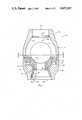
- FIG. 1is a longitudinal cross-section view of the ball-type check valve assembly in accordance with the present invention showing the elongated tubular member as a flexible skirt and showing the lower section thereof as a cross-section taken along lines 1--1 of FIG. 2;
- FIG. 2is a sectional view taken along lines 2--2 of FIG. 1;
- FIG. 3is a longitudinal cross-section view of the ball-type check valve assembly of the present invention showing the elongated tubular member as a rigid tubular member.
- the ball-type check valve 10 of FIG. 1is a preferred embodiment constructed according to the teachings of the present invention and includes a valve body 12 which has an upper portion 14 and a lower portion 16.
- the upper portion 14 and the lower portion 16are preferably connected by way of a twist-lock mechanism, but, other means, such as male and female threaded members, may be utilized.
- the upper portion 14has an inlet end 18 for directing the flow of fluid from a fluid flow line (not shown) to and through an inlet passageway 20. It is preferable, as shown in FIG. 1, that the inlet passageway 20 extends radially angularly from the inlet end 18 to facilitate the passage of fluid therethrough with minimal disturbance of a ball valve member which is located therein.
- the upper portion 14includes an upper ball seat 22 positioned adjacent the inlet end 18 between the inlet end 18 and the inlet passageway 20.
- the upper ball seat 22has an aperature 24 therein so that the inlet end 18 remains in fluid communication with the inlet passageway 20.
- the upper ball seat 22is constructed such that the surface 26 thereof extends radially outwardly and angularly from the aperature 24 so as to provide a surface adapted to sealingly cooperate with a ball valve member.
- the lower portion 16includes an outlet end 28 for directing the flow of fluid received from an outlet passageway 30 into the fluid flow line, the outlet passageway 30 being adapted to fluidly communicate with the inlet passageway 20.
- a ball retainer cup 32 having a first end portion 34 and a second end portion 36is positioned within the valve body 12 intermediate the inlet end 18 and the outlet end 28.
- the optimal position of the ball retainer cup 32will depend on the size of the ball valve member utilized since, to reduce turbulence within the valve assembly to a minimum, it is preferable to locate the center of the ball valve member when it is positioned upon the ball retainer cup 32 at the widest area of the inlet passageway 20.
- the ball retainer cup 32includes a passageway 38 extending therethrough so that fluid communication can be established between the inlet passageway 20 and the outlet passageway 30.
- the upper surface 40 of the ball retainer cup 32extends radially outwardly and upwardly from the passageway 38 thereby providing a surface 40 which is generally cone-shaped to facilitate sealing cooperation over a wide area of a ball valve member. Due to the shape of the surface 40, such surface 40 is not subjected to abrasive action of fluids passing thereover and, more importantly, facilitates the ball valve member seating over a wide area.
- the ball retainer cupis held in place within the check valve body 12 by spaced apart lug members 42.
- the lug members 42are spaced around and attached to the valve body 12 with the space between adjacent ones of the lug members 42 defining channels 44 which direct the flow of the fluid from the inlet passageway 20 and into the outlet passageway 30, such fluid entering the outlet passageway 30 at a first location 45 spaced from the outlet end 28.
- the lug members 42have end portions 46 which extend into slots 48 cut into the valve body 12 thereby providing means for supporting the lug members 42 to prevent them and the ball retainer cup 32 from being moved by the force exerted thereon by the flowing fluid.
- lug membersmay be attached in a variety of ways such as by welding and gluing, and that the ball retainer cup 32 may be held in place by other means so long as such other means includes one or more channels adapted to fluidly communicate the inlet passageway 20 with the outlet passageway 30.
- a flexible skirt 50has an end portion 51 which abuts the ball retainer cup 32 and, preferably, is attached to the ball retainer cup 32 at a position adjacent the passageway 38.
- the flexible skirt 50extends from the second end 36 of the ball retainer cup 32 through the outlet passageway 30 and terminates at another end portion 53 which is located at a second location 52 within the outlet passageway 30 between the first location 45 and the outlet end 28.
- the flexible skirt 50is constructed so as to abut the outlet passageway 30 at the second location 52 thereof so that fluid flow which enters through the outlet end 28 will not be directed into the channels 44, but, will be directed only through a passageway 54 extending through the flexible skirt 50.
- the passageway 54is in fluid communication with the passageway 38 extending through the ball retainer cup 32.
- a ball valve member 60is disposed within the valve body 12 and is movable between an open position and a closed position. In the open position, the ball valve member 60 rests upon the ball retainer cup 32 and seals off the passageway 38 so that all fluid communication between the inlet passageway 20 and the outlet passageway 30 by way of the passageway 38 is eliminated thereby directing the fluid flow into the channels 44. In the closed position, the ball valve member 60 rests upon the ball seat 22 thereby preventing flow of fluid in the reverse direction.
- the fluidthen flows through the passageway 54, into and through the passageway 38 which extends through the ball retainer cup 32, and to the underside portion of the ball valve member 60, whereby the ball valve member 60 is moved from an open position wherein the ball valve member 60 sealingly engages the surface 40 of the ball retainer cup 32 to a closed position wherein the ball valve member 60 sealingly engages the surface 26 of the upper ball seat 22 thereby closing off the check valve 10 and preventing further flow of the fluid in the reverse direction.
- alternate directions in which the fluid can flow through the check valve assembly 10are eliminated and, therefore, the number of directions from which the ball valve member is acted upon by the fluid is reduced to a single direction.
- FIG. 3shows an alternate embodiment of the ball-type check valve 10 of the present invention wherein the flexible skirt 50 is replaced with an elongated tubular member 70 of sufficiently rigid construction to prevent the member 70 from collapsing when relatively large volumes of fluid are passed through the check valve assembly 10.
- the rigid tubular member 70has one end portion 72 which abuts the ball retainer cup 32, and preferably is attached thereto, and another end portion 74 which extends into the outlet passageway 30 to the second location 52.
- the rigid tubular member 70includes a passageway 76 which is in fluid communication with the passageway 38 of the ball retainer cup 32 and is constructed to have an outside diameter which is less than the diameter of the outlet passageway 30 to permit fluid entering the outlet passageway 30 by way of the channels 44 to flow therearound and to and through the outlet end 28.
- a reduction in pressureoccurs within the passageway 76 of the rigid tubular member 70 when the fluid flowing through the outlet passageway 30 flows past the other end portion 74 of the tubular member 70.
- the reduction in pressure within the passageway 76draws the ball valve member 60 against the cone-shaped surface 40 of the ball retainer cup 32 to positively seat it thereupon until the fluid flow is stopped.
- valve body 12The preferred materials of construction of the valve body 12, the lug members 42, the ball retainer cup 32 and the upper ball seat 22 are well known high abrasion resistant and high temperature resistant thermoset plastics, particularly those comprised of the thermosetting phenolic resins.
- plastic materialsinclude reinforced nylons, polycarbonates, rigid acrylonitrile-butadiene-styrene copolymers and other rigid plastics.
- ceramic materialsare useful in this invention.
- Other materialsmay also be used depending on the particular use or application of the check valve assembly.
- suitable well known valve assembly metalssuch as aluminum, iron, steel, brass, copper and other metals used in customary valve constructions may be used in this invention.
- the preferred materials of construction of the rigid elongated tubular member 70are the well known high abrasion resistant and high temperature resistant thermoset plastics, particularly those comprised of thermosetting phenolic resins.
- Other plastic materials as well as metals similar to those used in constructing the valve body 12, the lug members 42, the ball retainer cup 32 and the upper ball seat 22can also be used in constructing the elongated tubular member 70.
- the preferred materials of construction of the flexible skirt 50are ethylene-oropylene-diene monomer rubber (EPDM) particular use or appllication of the ball-type check valve assembly.
- EPDMethylene-oropylene-diene monomer rubber
- nylonsrubber compounds, compounds of butadiene-acrylonitrile copolymers, vinyl chloride-vinylidene chloride copolymers, vinyl chloride-styrene copolymers, polytetrafluoro-ethylene polymers and other polymeric materials.
- the ball valve member 60can be constructed of a variety of well known materials typically utilized for ball valve members such as aluminum, and other frangible metals. Also, it may be made from one of the rigid plastics listed herein. It is preferred, however, that the ball valve member 60 be constructed of fabric reinforced phenolic compounds. Also, the ball valve member 60 may be coated with a suitable rubber compound to reduce wear on the ball valve member 60, the ball retainer cup 32, the upper ball seat 22 and the inlet passageway 20 and to allow the ball valve member to effectively sealingly cooperate with the ball retainer cup 32 and the upper ball seat 22.
- a ball-type check valve assembly particularly adapted to be used in float equipment used to cement casing in well borescan be constructed utilizing the aforementioned preferred materials.
- the check valve assembly constructed in this mannereffectively prevents backflow of the cement slurry, positively retains the ball valve member and such assembly can be easily drilled out with the drill bit once the cementing operation is complete in order to proceed with drilling the well.
Landscapes
- Engineering & Computer Science (AREA)
- General Engineering & Computer Science (AREA)
- Mechanical Engineering (AREA)
- Life Sciences & Earth Sciences (AREA)
- Geology (AREA)
- Mining & Mineral Resources (AREA)
- Physics & Mathematics (AREA)
- Environmental & Geological Engineering (AREA)
- Fluid Mechanics (AREA)
- General Life Sciences & Earth Sciences (AREA)
- Geochemistry & Mineralogy (AREA)
- Check Valves (AREA)
Abstract
Description
Claims (7)
Priority Applications (1)
| Application Number | Priority Date | Filing Date | Title |
|---|---|---|---|
| US06/820,544US4655247A (en) | 1986-01-17 | 1986-01-17 | Ball-type check valve assembly |
Applications Claiming Priority (1)
| Application Number | Priority Date | Filing Date | Title |
|---|---|---|---|
| US06/820,544US4655247A (en) | 1986-01-17 | 1986-01-17 | Ball-type check valve assembly |
Publications (1)
| Publication Number | Publication Date |
|---|---|
| US4655247Atrue US4655247A (en) | 1987-04-07 |
Family
ID=25231102
Family Applications (1)
| Application Number | Title | Priority Date | Filing Date |
|---|---|---|---|
| US06/820,544Expired - LifetimeUS4655247A (en) | 1986-01-17 | 1986-01-17 | Ball-type check valve assembly |
Country Status (1)
| Country | Link |
|---|---|
| US (1) | US4655247A (en) |
Cited By (37)
| Publication number | Priority date | Publication date | Assignee | Title |
|---|---|---|---|---|
| FR2598180A1 (en)* | 1986-05-01 | 1987-11-06 | Intevep Sa | BALLPOINT VALVE, IN PARTICULAR FOR SUBMERSIBLE PUMPS USED FOR PUMPING CRUDE OIL |
| US4945947A (en)* | 1989-05-26 | 1990-08-07 | Chromalloy American Corporation | Ball-type check valve |
| US5137056A (en)* | 1991-07-26 | 1992-08-11 | Lennox Industries Inc. | Air flapper valve assembly |
| US5411049A (en)* | 1994-03-18 | 1995-05-02 | Weatherford U.S., Inc. | Valve |
| US5450903A (en)* | 1994-03-22 | 1995-09-19 | Weatherford/Lamb, Inc. | Fill valve |
| US5680902A (en)* | 1994-03-22 | 1997-10-28 | Weatherford/Lamb, Inc. | Wellbore valve |
| US5836395A (en)* | 1994-08-01 | 1998-11-17 | Weatherford/Lamb, Inc. | Valve for wellbore use |
| US5909771A (en)* | 1994-03-22 | 1999-06-08 | Weatherford/Lamb, Inc. | Wellbore valve |
| US6210646B1 (en) | 1996-02-23 | 2001-04-03 | Ecowater Systems, Inc. | Permanganate feeder for iron filter |
| US6520256B2 (en) | 2001-04-20 | 2003-02-18 | Phillips Petroleum Co | Method and apparatus for cementing an air drilled well |
| EP1503119A1 (en)* | 2003-07-28 | 2005-02-02 | Uhde High Pressure Technologies GmbH | High pressure pump valve with replaceable valve seats |
| US20050161099A1 (en)* | 2002-05-28 | 2005-07-28 | Hiroshi Akema | Device for fluid processor and its fluid flow path setting device, fluid processor, and fluid processing method |
| US20060212037A1 (en)* | 2005-03-16 | 2006-09-21 | Alcon, Inc. | Pumping chamber for a liquefaction handpiece |
| US20060212039A1 (en)* | 2005-03-16 | 2006-09-21 | Alcon, Inc. | Pumping chamber for a liquefaction handpiece |
| US20080029161A1 (en)* | 2006-06-06 | 2008-02-07 | Albert Montague | Backflow preventer valve |
| US20090032121A1 (en)* | 2007-07-31 | 2009-02-05 | Chon James Y | Check Valve |
| US20090032123A1 (en)* | 2007-07-31 | 2009-02-05 | Bourne John M | Check Valve |
| US20100076471A1 (en)* | 2008-09-25 | 2010-03-25 | Bourne John M | Spring-Less Check Valve For A Handpiece |
| WO2011037704A1 (en)* | 2009-09-25 | 2011-03-31 | Illinois Tool Works Inc. | Gas regulator with safety valve assemblies |
| US20120241028A1 (en)* | 2009-10-23 | 2012-09-27 | Lyn Kirk | non-return valve assembly of the pivoting flap type, typically for insertion in floor drains |
| US20120248110A1 (en)* | 2011-03-31 | 2012-10-04 | Tony Wu | Airtight container |
| CN103615578A (en)* | 2013-11-26 | 2014-03-05 | 苏州大学 | Anti-backflow check valve |
| USD708402S1 (en) | 2012-06-27 | 2014-07-01 | Ctb, Inc. | Breather cap for use in connection with a watering assembly |
| US8904962B2 (en) | 2012-06-27 | 2014-12-09 | Ctb, Inc. | Breather cap assembly |
| US20150020784A1 (en)* | 2013-07-16 | 2015-01-22 | GM Global Technology Operations LLC | Dual flow check valve for positive crankcase ventilation system |
| US9255644B1 (en)* | 2011-05-11 | 2016-02-09 | William R. Voigt | Prompt hot water and water conservation system and method |
| WO2016047502A1 (en)* | 2014-09-22 | 2016-03-31 | 株式会社クレハ | Downhole tool member containing reactive metal, downhole tool provided with downhole tool member containing degradable resin composition, and well drilling method |
| JP2016060900A (en)* | 2014-09-22 | 2016-04-25 | 株式会社クレハ | Composition for excavating winze containing reactive metal and degradable resin composition, molded article for excavating winze, and method for excavating winze |
| US10119359B2 (en) | 2013-05-13 | 2018-11-06 | Magnum Oil Tools International, Ltd. | Dissolvable aluminum downhole plug |
| DE102017219004A1 (en)* | 2017-10-24 | 2019-04-25 | Brose Fahrzeugteile GmbH & Co. Kommanditgesellschaft, Würzburg | Electromotive oil pump with check valve |
| US10337279B2 (en) | 2014-04-02 | 2019-07-02 | Magnum Oil Tools International, Ltd. | Dissolvable downhole tools comprising both degradable polymer acid and degradable metal alloy elements |
| US20190254191A1 (en)* | 2018-02-14 | 2019-08-15 | Wistron Corporation | Backflow prevention device and server system using the same |
| US10465468B2 (en) | 2008-12-23 | 2019-11-05 | Magnum Oil Tools International, Ltd. | Downhole tools having non-toxic degradable elements |
| US10542731B2 (en) | 2012-06-27 | 2020-01-28 | Ctb, Inc. | Breather cap assembly |
| US11028682B1 (en)* | 2015-11-03 | 2021-06-08 | The University Of Tulsa | Eccentric pipe-in-pipe downhole gas separator |
| US20240026754A1 (en)* | 2022-07-20 | 2024-01-25 | Halliburton Energy Services, Inc. | Operating sleeve |
| US20240142009A1 (en)* | 2022-11-02 | 2024-05-02 | Danfoss A/S | Check valve and hydraulic gerotor or geroler machine |
Citations (5)
| Publication number | Priority date | Publication date | Assignee | Title |
|---|---|---|---|---|
| US1882314A (en)* | 1932-04-18 | 1932-10-11 | Baker Oil Tools Inc | Floating and cementing shoe |
| FR773742A (en)* | 1934-05-28 | 1934-11-24 | Hydrodynamic strainer valve | |
| FR1275628A (en)* | 1960-12-03 | 1961-11-10 | Oemv Ag | Ball valve |
| US3279545A (en)* | 1963-06-14 | 1966-10-18 | Jr John S Page | Storm choke |
| GB2102474A (en)* | 1981-07-13 | 1983-02-02 | Hughes Tool Co | Inside downhole blowout preventer |
- 1986
- 1986-01-17USUS06/820,544patent/US4655247A/ennot_activeExpired - Lifetime
Patent Citations (5)
| Publication number | Priority date | Publication date | Assignee | Title |
|---|---|---|---|---|
| US1882314A (en)* | 1932-04-18 | 1932-10-11 | Baker Oil Tools Inc | Floating and cementing shoe |
| FR773742A (en)* | 1934-05-28 | 1934-11-24 | Hydrodynamic strainer valve | |
| FR1275628A (en)* | 1960-12-03 | 1961-11-10 | Oemv Ag | Ball valve |
| US3279545A (en)* | 1963-06-14 | 1966-10-18 | Jr John S Page | Storm choke |
| GB2102474A (en)* | 1981-07-13 | 1983-02-02 | Hughes Tool Co | Inside downhole blowout preventer |
Cited By (59)
| Publication number | Priority date | Publication date | Assignee | Title |
|---|---|---|---|---|
| FR2598180A1 (en)* | 1986-05-01 | 1987-11-06 | Intevep Sa | BALLPOINT VALVE, IN PARTICULAR FOR SUBMERSIBLE PUMPS USED FOR PUMPING CRUDE OIL |
| US4945947A (en)* | 1989-05-26 | 1990-08-07 | Chromalloy American Corporation | Ball-type check valve |
| GB2232746A (en)* | 1989-05-26 | 1990-12-19 | Chromalloy American Corp | Ball-type check valve |
| GB2232746B (en)* | 1989-05-26 | 1993-09-29 | Chromalloy American Corp | Improved ball-type check valve |
| US5137056A (en)* | 1991-07-26 | 1992-08-11 | Lennox Industries Inc. | Air flapper valve assembly |
| US5411049A (en)* | 1994-03-18 | 1995-05-02 | Weatherford U.S., Inc. | Valve |
| US5450903A (en)* | 1994-03-22 | 1995-09-19 | Weatherford/Lamb, Inc. | Fill valve |
| US5680902A (en)* | 1994-03-22 | 1997-10-28 | Weatherford/Lamb, Inc. | Wellbore valve |
| US5690177A (en)* | 1994-03-22 | 1997-11-25 | Weatherford Lamb, Inc. | Fill valve |
| US5909771A (en)* | 1994-03-22 | 1999-06-08 | Weatherford/Lamb, Inc. | Wellbore valve |
| US5836395A (en)* | 1994-08-01 | 1998-11-17 | Weatherford/Lamb, Inc. | Valve for wellbore use |
| US6210646B1 (en) | 1996-02-23 | 2001-04-03 | Ecowater Systems, Inc. | Permanganate feeder for iron filter |
| US6520256B2 (en) | 2001-04-20 | 2003-02-18 | Phillips Petroleum Co | Method and apparatus for cementing an air drilled well |
| US7537028B2 (en)* | 2002-05-28 | 2009-05-26 | Jsr Corporation | Device for fluid processor and its fluid flow path setting device, fluid processor, and fluid processing method |
| US20050161099A1 (en)* | 2002-05-28 | 2005-07-28 | Hiroshi Akema | Device for fluid processor and its fluid flow path setting device, fluid processor, and fluid processing method |
| EP1503119A1 (en)* | 2003-07-28 | 2005-02-02 | Uhde High Pressure Technologies GmbH | High pressure pump valve with replaceable valve seats |
| US7758585B2 (en) | 2005-03-16 | 2010-07-20 | Alcon, Inc. | Pumping chamber for a liquefaction handpiece |
| US20060212039A1 (en)* | 2005-03-16 | 2006-09-21 | Alcon, Inc. | Pumping chamber for a liquefaction handpiece |
| US20060212037A1 (en)* | 2005-03-16 | 2006-09-21 | Alcon, Inc. | Pumping chamber for a liquefaction handpiece |
| US20080029161A1 (en)* | 2006-06-06 | 2008-02-07 | Albert Montague | Backflow preventer valve |
| US9587752B2 (en)* | 2006-06-06 | 2017-03-07 | SIVAN Valves, LLC | Backflow preventer valve |
| US20140137949A1 (en)* | 2006-06-06 | 2014-05-22 | SIVAN Valves, LLC | Backflow preventer valve |
| US8627847B2 (en)* | 2006-06-06 | 2014-01-14 | SIVAN Valves, LLC | Backflow preventer valve |
| US20090032121A1 (en)* | 2007-07-31 | 2009-02-05 | Chon James Y | Check Valve |
| US20090032123A1 (en)* | 2007-07-31 | 2009-02-05 | Bourne John M | Check Valve |
| US7849875B2 (en) | 2007-07-31 | 2010-12-14 | Alcon, Inc. | Check valve |
| US8291933B2 (en) | 2008-09-25 | 2012-10-23 | Novartis Ag | Spring-less check valve for a handpiece |
| US20100076471A1 (en)* | 2008-09-25 | 2010-03-25 | Bourne John M | Spring-Less Check Valve For A Handpiece |
| US10465468B2 (en) | 2008-12-23 | 2019-11-05 | Magnum Oil Tools International, Ltd. | Downhole tools having non-toxic degradable elements |
| US20110073200A1 (en)* | 2009-09-25 | 2011-03-31 | Illinois Tool Works Inc. | Gas regulator with valve assemblies |
| WO2011037704A1 (en)* | 2009-09-25 | 2011-03-31 | Illinois Tool Works Inc. | Gas regulator with safety valve assemblies |
| US9038660B2 (en)* | 2009-10-23 | 2015-05-26 | Lyn Kirk | Non-return valve assembly of the pivoting flap type, typically for insertion in floor drains |
| US20120241028A1 (en)* | 2009-10-23 | 2012-09-27 | Lyn Kirk | non-return valve assembly of the pivoting flap type, typically for insertion in floor drains |
| US20120248110A1 (en)* | 2011-03-31 | 2012-10-04 | Tony Wu | Airtight container |
| US9255644B1 (en)* | 2011-05-11 | 2016-02-09 | William R. Voigt | Prompt hot water and water conservation system and method |
| US10542731B2 (en) | 2012-06-27 | 2020-01-28 | Ctb, Inc. | Breather cap assembly |
| US10271526B2 (en) | 2012-06-27 | 2019-04-30 | Ctb, Inc. | Breather cap assembly |
| USD708402S1 (en) | 2012-06-27 | 2014-07-01 | Ctb, Inc. | Breather cap for use in connection with a watering assembly |
| US8904962B2 (en) | 2012-06-27 | 2014-12-09 | Ctb, Inc. | Breather cap assembly |
| US10352125B2 (en) | 2013-05-13 | 2019-07-16 | Magnum Oil Tools International, Ltd. | Downhole plug having dissolvable metallic and dissolvable acid polymer elements |
| US10119359B2 (en) | 2013-05-13 | 2018-11-06 | Magnum Oil Tools International, Ltd. | Dissolvable aluminum downhole plug |
| US20150020784A1 (en)* | 2013-07-16 | 2015-01-22 | GM Global Technology Operations LLC | Dual flow check valve for positive crankcase ventilation system |
| DE102014109587B4 (en) | 2013-07-16 | 2021-08-19 | GM Global Technology Operations, LLC (n.d. Ges. d. Staates Delaware) | Double-flow check valve for crankcase forced ventilation system |
| US9217343B2 (en)* | 2013-07-16 | 2015-12-22 | GM Global Technology Operations LLC | Dual flow check valve for positive crankcase ventilation system |
| CN103615578A (en)* | 2013-11-26 | 2014-03-05 | 苏州大学 | Anti-backflow check valve |
| US10337279B2 (en) | 2014-04-02 | 2019-07-02 | Magnum Oil Tools International, Ltd. | Dissolvable downhole tools comprising both degradable polymer acid and degradable metal alloy elements |
| WO2016047502A1 (en)* | 2014-09-22 | 2016-03-31 | 株式会社クレハ | Downhole tool member containing reactive metal, downhole tool provided with downhole tool member containing degradable resin composition, and well drilling method |
| RU2670292C1 (en)* | 2014-09-22 | 2018-10-22 | Куреха Корпорейшн | Downhole tool equipped with element of downhole tool containing chemically active metal and with element of downhole tool containing decomposable resin composition and method of drilling wells |
| JP2016061127A (en)* | 2014-09-22 | 2016-04-25 | 株式会社クレハ | Downhole tool comprising downhole tool member containing reactive metal and downhole tool member containing decomposable resin composition, and winze drilling method |
| RU2707212C2 (en)* | 2014-09-22 | 2019-11-25 | Куреха Корпорейшн | Downhole tool equipped with a downhole tool element containing a chemically active metal and a downhole tool element containing a degradable resin composition, and a well drilling method |
| JP2016060900A (en)* | 2014-09-22 | 2016-04-25 | 株式会社クレハ | Composition for excavating winze containing reactive metal and degradable resin composition, molded article for excavating winze, and method for excavating winze |
| US11028682B1 (en)* | 2015-11-03 | 2021-06-08 | The University Of Tulsa | Eccentric pipe-in-pipe downhole gas separator |
| DE102017219004A1 (en)* | 2017-10-24 | 2019-04-25 | Brose Fahrzeugteile GmbH & Co. Kommanditgesellschaft, Würzburg | Electromotive oil pump with check valve |
| US12305639B2 (en) | 2017-10-24 | 2025-05-20 | Brose Fahrzeugteile SE & Co. Kommanditgesellschaft, Würzburg | Electromotive oil pump comprising a non-return valve |
| US20190254191A1 (en)* | 2018-02-14 | 2019-08-15 | Wistron Corporation | Backflow prevention device and server system using the same |
| US10779434B2 (en)* | 2018-02-14 | 2020-09-15 | Wistron Corporation | Backflow prevention device and server system using the same |
| US20240026754A1 (en)* | 2022-07-20 | 2024-01-25 | Halliburton Energy Services, Inc. | Operating sleeve |
| US11965397B2 (en)* | 2022-07-20 | 2024-04-23 | Halliburton Energy Services, Inc. | Operating sleeve |
| US20240142009A1 (en)* | 2022-11-02 | 2024-05-02 | Danfoss A/S | Check valve and hydraulic gerotor or geroler machine |
Similar Documents
| Publication | Publication Date | Title |
|---|---|---|
| US4655247A (en) | Ball-type check valve assembly | |
| CA2292663C (en) | Valve for use in a wellbore | |
| EP0752047B1 (en) | Fill valve | |
| US4945947A (en) | Ball-type check valve | |
| US6923255B2 (en) | Activating ball assembly for use with a by-pass tool in a drill string | |
| US5494107A (en) | Reverse cementing system and method | |
| US6877565B2 (en) | Arrangement for the removal of cuttings and gas arising from drilling operations | |
| US2771091A (en) | Drill pipe float valve | |
| US4360064A (en) | Circulating valve for wells | |
| US5201371A (en) | Back pressure flapper valve | |
| US1854518A (en) | Cement barrel | |
| US2744727A (en) | Drill pipe float valve | |
| US6491103B2 (en) | System for running tubular members | |
| US6684957B2 (en) | Float collar | |
| US4069840A (en) | Ball check valve | |
| US2750958A (en) | Drill pipe float valve | |
| US5680902A (en) | Wellbore valve | |
| US2565742A (en) | Fluid pressure control device | |
| SE516647C2 (en) | Impact drill bit and impact drill with springless non-return valve and method for blocking backflowing fluid | |
| US3011511A (en) | Air or gas lift valves | |
| US3369619A (en) | Pressure control device | |
| CN211314144U (en) | Throttling bypass valve for continuous oil pipe | |
| RU2115798C1 (en) | Non-return valve for casing strings | |
| US3717203A (en) | Automatic well shut-off apparatus | |
| RU178337U1 (en) | CHECK VALVE FOR PREVENTING SLUDGE SLAMMING |
Legal Events
| Date | Code | Title | Description |
|---|---|---|---|
| AS | Assignment | Owner name:CHROMALLOY AMERICAN CORPORATION, 120 SOUTH CENTRAL Free format text:ASSIGNMENT OF ASSIGNORS INTEREST.;ASSIGNORS:WESTRA, LUBBERT;LIRETTE, BRENT J.;REEL/FRAME:004515/0102 Effective date:19860116 | |
| STCF | Information on status: patent grant | Free format text:PATENTED CASE | |
| CC | Certificate of correction | ||
| FEPP | Fee payment procedure | Free format text:PAYOR NUMBER ASSIGNED (ORIGINAL EVENT CODE: ASPN); ENTITY STATUS OF PATENT OWNER: LARGE ENTITY | |
| FPAY | Fee payment | Year of fee payment:4 | |
| AS | Assignment | Owner name:SEQUA ENGINEERED SERVICES, INC., A WEST VIRGINIA C Free format text:ASSIGNMENT OF ASSIGNORS INTEREST.;ASSIGNOR:CHROMALLOY AMERICAN CORPORATION, A DE CORP.;REEL/FRAME:005853/0137 Effective date:19910912 | |
| AS | Assignment | Owner name:WEATHERFORD-PETCO, INC., TEXAS Free format text:ASSIGNMENT OF ASSIGNORS INTEREST;ASSIGNOR:SEQUA ENGINEERED SERVICES, INC.;REEL/FRAME:006674/0275 Effective date:19921111 | |
| AS | Assignment | Owner name:TEXAS COMMERCE BANK NATIONAL ASSOICATION, TEXAS Free format text:SECURITY INTEREST;ASSIGNOR:WEATHERFORD U.S., INC.;REEL/FRAME:006677/0420 Effective date:19930331 | |
| AS | Assignment | Owner name:WEATHERFORD U.S., INC., TEXAS Free format text:RELEASE FROM SECURITY AGREEMENT;ASSIGNOR:TEXAS COMMERCE BANK NATIONAL ASSOCIATION;REEL/FRAME:006968/0187 Effective date:19940415 | |
| FPAY | Fee payment | Year of fee payment:8 | |
| SULP | Surcharge for late payment | ||
| REMI | Maintenance fee reminder mailed | ||
| FEPP | Fee payment procedure | Free format text:PAYER NUMBER DE-ASSIGNED (ORIGINAL EVENT CODE: RMPN); ENTITY STATUS OF PATENT OWNER: LARGE ENTITY | |
| FPAY | Fee payment | Year of fee payment:12 |