US4655197A - Lavage system with variable frequency, flow rate and pressure - Google Patents
Lavage system with variable frequency, flow rate and pressureDownload PDFInfo
- Publication number
- US4655197A US4655197AUS06/445,793US44579382AUS4655197AUS 4655197 AUS4655197 AUS 4655197AUS 44579382 AUS44579382 AUS 44579382AUS 4655197 AUS4655197 AUS 4655197A
- Authority
- US
- United States
- Prior art keywords
- pressure
- frequency
- lavage
- pump
- fluid flow
- Prior art date
- Legal status (The legal status is an assumption and is not a legal conclusion. Google has not performed a legal analysis and makes no representation as to the accuracy of the status listed.)
- Expired - Lifetime
Links
Images


Classifications
- A—HUMAN NECESSITIES
- A61—MEDICAL OR VETERINARY SCIENCE; HYGIENE
- A61M—DEVICES FOR INTRODUCING MEDIA INTO, OR ONTO, THE BODY; DEVICES FOR TRANSDUCING BODY MEDIA OR FOR TAKING MEDIA FROM THE BODY; DEVICES FOR PRODUCING OR ENDING SLEEP OR STUPOR
- A61M3/00—Medical syringes, e.g. enemata; Irrigators
- A61M3/02—Enemata; Irrigators
- A61M3/0233—Enemata; Irrigators characterised by liquid supply means, e.g. from pressurised reservoirs
- A61M3/0254—Enemata; Irrigators characterised by liquid supply means, e.g. from pressurised reservoirs the liquid being pumped
- A61M3/0258—Enemata; Irrigators characterised by liquid supply means, e.g. from pressurised reservoirs the liquid being pumped by means of electric pumps
- A—HUMAN NECESSITIES
- A61—MEDICAL OR VETERINARY SCIENCE; HYGIENE
- A61M—DEVICES FOR INTRODUCING MEDIA INTO, OR ONTO, THE BODY; DEVICES FOR TRANSDUCING BODY MEDIA OR FOR TAKING MEDIA FROM THE BODY; DEVICES FOR PRODUCING OR ENDING SLEEP OR STUPOR
- A61M1/00—Suction or pumping devices for medical purposes; Devices for carrying-off, for treatment of, or for carrying-over, body-liquids; Drainage systems
- A61M1/71—Suction drainage systems
- A61M1/74—Suction control
- A61M1/741—Suction control with means for varying suction manually
- A61M1/7413—Suction control with means for varying suction manually by changing the cross-section of the line
- A61M1/7415—Suction control with means for varying suction manually by changing the cross-section of the line by deformation of the fluid passage
- A—HUMAN NECESSITIES
- A61—MEDICAL OR VETERINARY SCIENCE; HYGIENE
- A61M—DEVICES FOR INTRODUCING MEDIA INTO, OR ONTO, THE BODY; DEVICES FOR TRANSDUCING BODY MEDIA OR FOR TAKING MEDIA FROM THE BODY; DEVICES FOR PRODUCING OR ENDING SLEEP OR STUPOR
- A61M1/00—Suction or pumping devices for medical purposes; Devices for carrying-off, for treatment of, or for carrying-over, body-liquids; Drainage systems
- A61M1/71—Suction drainage systems
- A61M1/77—Suction-irrigation systems
- A—HUMAN NECESSITIES
- A61—MEDICAL OR VETERINARY SCIENCE; HYGIENE
- A61M—DEVICES FOR INTRODUCING MEDIA INTO, OR ONTO, THE BODY; DEVICES FOR TRANSDUCING BODY MEDIA OR FOR TAKING MEDIA FROM THE BODY; DEVICES FOR PRODUCING OR ENDING SLEEP OR STUPOR
- A61M3/00—Medical syringes, e.g. enemata; Irrigators
- A61M3/02—Enemata; Irrigators
- A61M3/0204—Physical characteristics of the irrigation fluid, e.g. conductivity or turbidity
- A61M3/0208—Physical characteristics of the irrigation fluid, e.g. conductivity or turbidity before use
- A—HUMAN NECESSITIES
- A61—MEDICAL OR VETERINARY SCIENCE; HYGIENE
- A61M—DEVICES FOR INTRODUCING MEDIA INTO, OR ONTO, THE BODY; DEVICES FOR TRANSDUCING BODY MEDIA OR FOR TAKING MEDIA FROM THE BODY; DEVICES FOR PRODUCING OR ENDING SLEEP OR STUPOR
- A61M3/00—Medical syringes, e.g. enemata; Irrigators
- A61M3/02—Enemata; Irrigators
- A61M3/0204—Physical characteristics of the irrigation fluid, e.g. conductivity or turbidity
- A61M3/0212—Physical characteristics of the irrigation fluid, e.g. conductivity or turbidity after use
- A—HUMAN NECESSITIES
- A61—MEDICAL OR VETERINARY SCIENCE; HYGIENE
- A61M—DEVICES FOR INTRODUCING MEDIA INTO, OR ONTO, THE BODY; DEVICES FOR TRANSDUCING BODY MEDIA OR FOR TAKING MEDIA FROM THE BODY; DEVICES FOR PRODUCING OR ENDING SLEEP OR STUPOR
- A61M3/00—Medical syringes, e.g. enemata; Irrigators
- A61M3/02—Enemata; Irrigators
- A61M3/0204—Physical characteristics of the irrigation fluid, e.g. conductivity or turbidity
- A61M3/0216—Pressure
- A—HUMAN NECESSITIES
- A61—MEDICAL OR VETERINARY SCIENCE; HYGIENE
- A61M—DEVICES FOR INTRODUCING MEDIA INTO, OR ONTO, THE BODY; DEVICES FOR TRANSDUCING BODY MEDIA OR FOR TAKING MEDIA FROM THE BODY; DEVICES FOR PRODUCING OR ENDING SLEEP OR STUPOR
- A61M3/00—Medical syringes, e.g. enemata; Irrigators
- A61M3/02—Enemata; Irrigators
- A61M3/0204—Physical characteristics of the irrigation fluid, e.g. conductivity or turbidity
- A61M3/022—Volume; Flow rate
- A—HUMAN NECESSITIES
- A61—MEDICAL OR VETERINARY SCIENCE; HYGIENE
- A61M—DEVICES FOR INTRODUCING MEDIA INTO, OR ONTO, THE BODY; DEVICES FOR TRANSDUCING BODY MEDIA OR FOR TAKING MEDIA FROM THE BODY; DEVICES FOR PRODUCING OR ENDING SLEEP OR STUPOR
- A61M3/00—Medical syringes, e.g. enemata; Irrigators
- A61M3/02—Enemata; Irrigators
- A61M3/0275—Pulsating jets; Vibrating nozzles
- A—HUMAN NECESSITIES
- A61—MEDICAL OR VETERINARY SCIENCE; HYGIENE
- A61M—DEVICES FOR INTRODUCING MEDIA INTO, OR ONTO, THE BODY; DEVICES FOR TRANSDUCING BODY MEDIA OR FOR TAKING MEDIA FROM THE BODY; DEVICES FOR PRODUCING OR ENDING SLEEP OR STUPOR
- A61M1/00—Suction or pumping devices for medical purposes; Devices for carrying-off, for treatment of, or for carrying-over, body-liquids; Drainage systems
- A61M1/71—Suction drainage systems
- A61M1/74—Suction control
- A61M1/741—Suction control with means for varying suction manually
- A61M1/7413—Suction control with means for varying suction manually by changing the cross-section of the line
Definitions
- the inventionin general relates to the field of medical, dental and therapeutic lavage, and more particularly to a mechanized lavage system in which the rate of fluid flow and the average fluid pressure, are variable.
- Lavageor the washing of tissue, is perhaps as old as medicine itself.
- fluidgenerally a liquid such as water
- tissueto wash away dirt or debris.
- mechanized lavage systemshave become common.
- U.S. Pat. No. 3,902,664 issued to Üsdiscloses a fluid pulsator in which the frequency of pulsation may be changed. Analysis of the system indicates that the change of frequency is accomplished by changing the back pressure created in the device and thereby altering the rate of flow of fluid through the device.
- the instantaneous pressure within each individual pulse as it energes from the exit valve of the pulsating mechanismmay remain approximately constant throughout a wide range of frequencies, it is also evident that the average pressure of the fluid flow will change considerably over the frequency range since the rate of fluid flow changes considerably.
- the change in average pressurewill cause the instantaneous pressure within each pulse to change well before it leaves the lavage tube.
- suctionaspiration
- This suction functionhas been found to be useful and necessary to remove the lavage fluid to create a clear field, for example, when the lavage is used to cleanse a wound during surgery, and also to remove the debris when pulsatile lavage is used for debridement purposes.
- the throttle type controlnecessarily is inefficient since it causes the motor providing the irrigation or lavage function to waste energy as the motor struggles to force the fluid through a constricted opening. In most systems, the result is that the motor is ironically forced to produce the highest pressures precisely at the time when reduced pressure at the lavage head is used. In addition to wasted energy, such throttle systems result in shortened life for mechanical parts, and considerably increased operating noise of the system. These factors were perhaps not seen as disadvantages in the prior art system; however it has been found that the present invention has removed these characteristics in a unexpected and thorough fashion that now reveals them to be quite undesirable, when the controllability, quietness and efficiency of the lavage and irrigation system of the present invention is compared to the prior art.
- Another object of the inventionis to provide a lavage system in which the rate of fluid flow or the pressure may be varied by varying the length of stroke of the fluid driving means.
- a further object of the inventionis to provide a lavage system in which the frequency may be varied over a wide range without altering the rate of fluid flow or fluid pressure.
- Another object of the inventionis to provide a lavage system in which the rate of fluid flow or fluid pressure may be varied over a wide range without altering the pumping frequency of the irrigation and suction functions, and without altering the fluid pulsation frequency of the pulsatile lavage function.
- Yet another object of the inventionis to provide a lavage system having a pulsatile lavage mode in which the frequency and rate of flow (pressure) are separately controllable and settable, and an irrigation mode in whcih the pulsation frequency of the fluid stream is fixed and may be ignored while the rate of flow or pressure may be varied.
- Still another object of the inventionis to provide a lavage system in which the fluid pulsation frequency, the rate of fluid flow, the average fluid pressure, and the pumping frequency each may be controlled with high accuracy.
- the inventioncomprises a lavage apparatus which included a means for producing a pulsating fluid flow, and a means for varying the pulsation frequency of the fluid flow while maintaining the pressure or rate of fluid flow substantially constant.
- the lavage apparatusalso includes a means for varying the fluid pressure or the rate of fluid flow while maintaining the pulsation frequency constant.
- the preferred systemalso includes a means for fixing the frequency at a predetermined frequency, a switch having a first position in which the means for varying the frequency is enabled to control the pulsation frequency and a second position in which the means for fixing the frequency is enabled to control the pulsation frequency, and wherein the means for varying the pressure or rate of fluid flow includes a first manually settable control for controlling the pressure or rate of fluid flow and a second manually settable control for controlling the pressure or rate of flow and the switch switches control of the pressure or rate to the first control when the switch is in the first position and switches control of the pressure or rate to the second control when the switch is in the second position.
- the inventioncomprises a medical, dental or therapeutic lavage system of the type having a chamber having an inlet and an outlet, a means for imparting a flow to fluid moving from the inlet to the outlet within the chamber, and a means for varying the pressure or rate of fluid flow characterized by the improvement comprising the means for imparting including a fluid driving means moving along a repetitive stroke, and the pressure or rate varying means including a means for varying the length of stroke of the fluid driving means.
- the lavage system provided by the inventionis surprisingly effective in removing debris from a wide range of tissues. lt is believed that this is due to the fact that various tissues have different natural frequencies of vibration and that the optimum pulsation frequency for debridement is related to these natural frequencies, and thus the ability to accurately control the pulsation frequency permits optimization of the debridement function for a wide variety of tissues for which this was not previously possible.
- the ability to accurately control rate of flow, while the frequency is being varied to find the optimum frequencygreatly enhances the ability of the physician to find the proper frequency since the situation is not complicated by a simultaneously changing flow. Further, it has been discovered that the quietness of the machine makes it significantly more welcome in the hospital and other medical therapeutic environments.
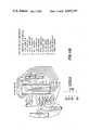
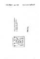
- FIG. 1is a front view of a lavage system in accordance with a preferred embodiment of the invention
- FIG. 2is a partial rear view of the lavage system of FIG. 1;
- FIG. 3is a front view of the housing for the lavage system of FIG. 1;
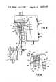
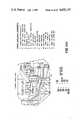
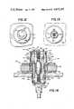
- FIG. 4is a sectional view of the preferred embodiment of the lavage handpiece
- FIG. 5is a side view of the housing of FIG. 3 showing the preferred pulsatile lavage/irrigation pumping chamber
- FIG. 6is a side view of the housing showing the suction pumping chamber, and indicating the manner of insertion of the pump;
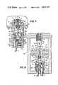
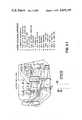
- FIG. 7is a (cut-away) sectional view taken along line 7--7 of FIG. 2, showing the preferred suction pumping chamber and an embodiment of a motor according to the invention;
- FIG. 8is a (cut-away) sectional view taken along line 8--8 of FIG. 2, showing the pulsatile lavage/irrigation pumping chamber used in the invention;
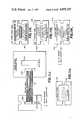
- FIG. 9is a block diagram showing the operation of the controls and various functions of the preferred embodiment of the invention.
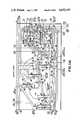
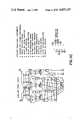
- FIG. 10Ais the upper half and FIG. 10B is the lower half of a schematic diagram of the electronics according to the preferred embodiment of the invention.
- FIGS. 11A thru 11Lshow more detailed electrical diagrams of the various portions of the electronics of FIGS. 10A and 10B;
- FIG. 12is a top view of the preferred linear reciprocating motor according to the invention.
- FIG. 13is a bottom view of the motor of FIG. 12.
- FIG. 14is a cross-sectional view of the motor of FIG. 12, taken along lines 14--14.
- the systemincludes a housing 11 mounted on a movable stand 13 along with a supply 15 of fluid such as saline solution.
- a drainage tank 17below the housing 11 and also mounted to the stand 13 is a drainage tank 17.
- the fluid supply 15is connected to a pulsatile lavage/irrigation pump 51A (not shown in these figures) in the housing 11 by line 19, and the drainage tank 17 is likewise connected to a suction pump 51B (also not shown) in the housing 11 by line 21.
- a pulsatile lavage/irrigation fluid line 23connects the pump 51A to a lavage handpiece 27 to provide a stream of fluid at nozzle 143B.
- a suction line 25connects the lavage handpiece 27 to the drainage tank 17.
- the vacuum line 21, connecting the drainage tank 17 to the suction pump 51B in the housing 11,provides fluid suction at the nozzle 143A via line 25.
- the housing 11contains circuitry and pumps which provide pulsatile lavage and irrigation functions by pumping fluid from the supply 15 to the lavage head 27 via line 23 and provide an aspirating function by pumping fluid from the lavage head 27 via line 25 to the drainage tank 17 by providing vacuum at line 21.
- PL/IRthe pump and the associated components which provide both the pulsatile lavage and irrigation functions
- the pulsatile lavage, irrigation and suction functionsare controlled at control board 29.
- a pair of switches 31, 33operate the PL/IR and suction pumps, respectively.
- the suction control switch 33is a two-position on/off switch, while the PL/IR control switch 31 is a three-position switch having an "off” position, a "lavage” (here short for pulsatile lavage) position and an "irrigation” position.
- the PL/IR control switch 31is used to switch the PL/IR motor from “off” to "lavage” and “irrigation" control modes with "lavage" mode control being effected by control knobs 35 and 37 and "irrigation" mode control being effected by knob 39.
- the suction pumpis operable in only a single "suction" mode which is controlled by knob 41.
- the systemcan be controlled in three “on” modes: “lavage,” “irrigation,” and “suction.”
- lavagewhen used in connection with knob 31 is short for the term pulsatile lavage used elsewhere herein.
- both the “lavage” and “irrigation” modesprovide irrigation in the sense that they both provide a stream of liquid.
- suctionis generally considered to be an integral part of surgical lavage. For this reason, the choice of terminology chosen to distinguish the three functions of the preferred system should not be considered to be limiting when these terms are used in somewhat different senses in other contexts.
- Stand 13includes a collar 10 for adjusting the height of the upper portion, and thus the height of fluid supply, above the housing 11.
- Housing 11includes knobbed set screws 14A and 14B for adjusting its height on stand 13.
- Drainage tank 17also includes a knobbed set screw 12 for adjustment of its height.
- the systemalso includes tubes 24A and 24B.
- One end of line 24Aconnects to "T" 22A in line 23 and the other end connects to the pressure transducer coupling 24D.
- the connectionis made by means of a leur lock connector 24F having a filter 28 attached to prevent contamination of the fluid in tube 23 by transducer 26A (FIG. 5).
- One end of line 24Bconnects to "T" 22B in line 21 and the other end connects to suction transducer coupling 24E via leur lock connector 24C.
- the transducers 26A and 26Bwill be discussed in more detail in connection with FIG. 9.
- a disposable drainage bag 18which optionally fits within tank 17. In a third alternative of the drainage system bag 18 may be replaced by a disposable rigid cannister.
- the lavage handpiece 27 in the preferred embodimentincludes a pistol-shaped body 132 and a pair of pinch valves 133 and 135, which are secured in hollows molded in body 132.
- a pair of cylindrical channels 134A and 134Bare formed within body 132 of an appropriate size to accept the ends of tubing 23 and 25.
- Pinch valve 133is rotatable about pin 136 to pinch off tubing 23.
- Serrated arm 137holds pinch valve 135 in an open or closed position. It is made of a flexible material so that it may be raised upward to release pinch valve 135 as desired.
- a nozzle tube assembly 141which comprises two semi-rigid tubes 142A and 142B held in a plug 140, and a pair of nozzles 143A and 143B (FIG. 1) attached to the ends of tubes 142A and 142B respectively.
- the proximal ends of tubes 142A and 142Bfit into the open ends 139 of tubes 23 and 25.
- these nozzles and tubesform a replaceable assembly, which is described in detail in a companion application. Since the particular form of the nozzles are not a part of this invention they will not be discussed further herein.
- each pump 51A and 51Bis attached to an electric driving motor, which in the preferred embodiment is a linear reciprocating motor; however, only one motor 53 is shown (attached to pump 51B) as the other motor is identical.
- Each motor, such as 53is connected to its pump, such as 51B, by a coupling 59.
- Each coupling 59consists of a pin 61 and a pair of flange sections 63, 65 associated with the motors 53 and pumps (51A or 51B) respectively.
- Each pin 61is located on the motor flange 63 and inserts into a hole 57 in the pump flange 65.
- Each flange 65is connected to a piston rod; piston rod 67A in the case of pump 51A and piston rod 67B in the case of pump 51B.
- the pumpincludes a pump body 55B having an upper portion 152 and a lower portion 157 which enclose a cylindrical chamber, which chamber is divided into a upper portion 150 and an lower portion 153 by a diaphragm 151.
- Diaphragm 151includes an outer lip 155 which is secured between the two housing portions 152 and 157.
- the center part of diaphragm 151is sandwiched between a cup 159 and washer 163 and the assembly is secured to shaft 67B by a screw 161 which screws into a threaded hole 167 in the end of shaft 67B.
- Inlet umbrella valve 171 and outlet umbrella valve 173seat in inlet and outlet passageways to chamber 153.
- Filter 175seats in the lower portion of the outlet passageway.
- the PL/IR pump 51Ais built somewhat differently than the suction pump because of its different function.
- the molded pumping housing 66Aencloses a cylindrical chamber 189 which is sealed by plunger 179, which is comprised of two O-rings 181 which fit into grooves in the end of shaft 67A.
- the outlet and inlet valves 187 and 188respectively are ball valves comprised of resilient balls such as 185 which are normally held in the closed position by springs 186.
- FIG. 6the apparatus for holding a pump within the housing 11 shall be described in reference to the suction pump 51B.
- An upper pair of flanges 69B and a lower pair of flanges 69B'extend from the pumping chamber housing 66B.
- a suction pump support 70Bwhich is shaped somewhat like a four-prong tuning fork having prongs 71B.
- Pump 51Bfits into enclosure 68B with flanges 69 passing above the upper pair of prongs 71B and flanges 69B passing below the lower pair of prongs 71B.
- a backing plate 78(not shown in FIG.
- pump 51Ais likewise secured in enclosure 68A by slipping flanges 69A and 69A' about prongs 71A and, closing door 74A so that wedges 75A force prongs 71A open, slipping rod 82A into slot 80A and screwing nut 84A tight to secure the door.
- the motor 53is a linear reciprocating motor. It comprises a coil 83 and a core 86.
- Coil 83is fixed to reciprocating section 77 of motor 53.
- Core 86comprises an outer permanent magnet portion 79 and an inner nonmagnetized but magnetically permeable portion 85.
- a cylindrical slot 81is formed within core 86, and coil 83 moves within this slot.
- Magnetically permeable steel plates 76A and 76Bsandwich the permanent magnet, and also may be considered as part of the motor core.
- Coil 83is mounted on a circular support 87 which is attached to shaft 89 by screw 88.
- a hollow cylindrical bearing 90fits into a cylindrical bore in core 86 and shaft 89 slides within bearing 90.
- Helical coil spring 91is located on shaft 89 with the axis of the spring corresponding to the axis of the shaft, and with one end of the spring seating against support 87 and the other end of the spring seated against bushing 90.
- the coil spring 93fits coaxially about the bottom of the shaft 89 and seats between the top of flange 63 and a spring enclosure 94 which forms an integral part of bushing 90.
- the springs 91 and 93will function properly as long as one end is seated against a portion of the motor that is moveable with the coil while the other end is seated against a portion of the motor which is fixed to the core.
- bushing 90may in this embodiment be considered to be part of the motor core.
- Coil 83is electrically connected to circuitry in the housing by means of braided wires 95.
- FIGS. 12, 13, and 14an alternative embodiment of the linear motor is shown. This embodiment is presently the preferred embodiment.
- a top view of the motoris shown in FIG. 12, a bottom view in FIG. 13, and a cross-sectional view in FIG. 14.
- Motor 201comprises a core 202 and a moving coil 213.
- Core 202includes a magnetically permeable top plate 203, a magnetically permeable bottom plate 204, an inner magnetically permeable core 208 and a permanent magnet 209.
- Coil 213moves in a cylindrical slot 211 between magnet 209 and inner core 208.
- Coil 213is attached to a cylindrical coil support 214 which in turn is attached to a ring-shaped flange 218 on top disc-shaped support 217.
- Top support 217is secured to a disc-shaped bottom support 221 by three shafts 219 by means of screws such as 222. Shafts 219 are moveable in bearings 227 which seat in cylindrical bores 228 through core 202.
- Coil springs 225seat between the core 202 and supports 217 and 221. Spring alignment bosses 223 are attached to the center of supports 217 and 221 and spring alignment post 224 seats in a cylindrical bore through the center of core 202. One end of the spring 225 fits around the bosses 223 and the other end fits around the post 224 to maintain the spring in alignment.
- Springs 225are helical coil springs with variable coil spacing; that is, the coil spacing at one portion 225A of each spring 225 is different than the coil spacing at another portion 225B of the same spring 225.
- the motoris attached to flange 229 by screw 230, and the rest of the attachment to the pump is as described above.
- the motor 201sits in a cylindrical hole 232 in pump housing 233.
- a thermistor, such as 128,is encapsulated in epoxy and bolted to the support 217 and is connected to the electronic circuitry, which shall be described below, by braided wires 127.
- Coil 213is connected to the electronic circuitry by braided wires 212.
- FIG. 9a discussion of the electrical circuitry in terms of a functional diagram will be given before proceeding to the detailed discussion of the circuitry, in order to make that discussion more clear.
- Power for the motors 53a and 53bis supplied by signals provided by amps 101 and 102 respectively which is supplied to the motors through circuit breakers 123 and 124 respectively.
- Oscillating signals which are amplified by amplifiers 101 and 102are provided by oscillators 105 and 106 respectively. Power to the oscillators is provided through circuit breaker 125.
- the switches in FIG. 9correspond to the switches in FIG. 3. These switches are actually double pole switches.
- the two poles of switch 31are shown separately at 31a and 31b in FIG. 9 for clarity.
- the dotted lineindicates that the two switches move together.
- switch 33has a closed position in which it connects the fixed oscillator 106 to the suction amplifier 102, which is the suction "on” position, and an open circuit position which is the suction "off” position. In the "on” position switch 33 also activates meter 122 to read the vacuum from the suction transducer 26B. This is shown by the dotted line. Meter 122 could also be connected to read the power going through variable resistor 107, or the power off the amplifier 102, both of which would give a meaningful output to the meter.
- the far left position of switches 31a and 31bis an open circuit "off" position.
- switch 31aconnects variable resistor 109, which is controlled by knob 35, into the circuit between oscillator 105 and amp 101.
- Variable resistor 109controls the amplitude of the signal to amplifier 101 and thus controls the power output of the amplifier and ultimately of the pump.
- meter 119can be calibrated in either percent of power units, pressure units, or rate of flow units. In the embodiment described, it is chosen to calibrate the meter in pressure units, and the pressure is read off pressure transducer 26A by meter 119 when switch 31a is in the central position.
- the pressure units chosenare pounds per square inch.
- switch 31bconnects variable resistance 113 into the variable oscillator 105 circuitry.
- Variable resistance 113is controlled by knob 37, the pulsatile lavage frequency control, to control the frequency of variable oscillator 105.
- switch 31balso connects meter 117 to the circuitry of variable oscillator 105. In this position of switch 31b meter 117 displays the frequency of oscillation of the variable oscillator 105.
- switch 31aconnects variable resistance 111 between oscillator 105 and amplifier 101.
- Variable resistance 111is controlled by knob 39 which, as can be seen from FIG. 3, is the irrigation power control.
- Meter 121displays the output of variable resistance 111. Again this output can be calibrated in either pressure units, rate of flow units, or a power unit. In the present embodiment it is chosen to calibrate it in percent of flow.
- switch 31bconnects variable resistor 115 into the electrical circuit of variable oscillator 105.
- Variable resistance 115is not controlled by an external knob, but rather is controlled by a "behind the set” control which determines the "fixed" frequency of the irrigation mode. Generally this resistance is set so that a high oscillation frequency, i.e. in the range between 30 and 40 cycles per second is chosen since a high frequency provides a nearly continuous flow.
- switch 31bwhen switched to the far right position deactivates the meter 117, although one obviously could choose to leave the meter connected in this situation if one desired to read out the "fixed" frequency.
- variable resistance 116The oscillation frequency of fixed oscillator 106 is determined by variable resistance 116, which is also a "behind the set" control.
- the setting of variable resistance 116determines the frequency of the suction motor and pump.
- thermistors 128 and 129which are physically attached to motors 53a and 53b as shown by the dotted lines.
- Thermistors 128 and 129are temperature sensitive resistors which in a voltage divider circuit will vary the voltage output of the circuit proportionally to the temperature of the motor. As the temperature of the motor increases the internal resistance of the moving coil increases which reduces the effective power produced by the motor.
- the output of the voltage divider circuit incorporating thermistors 128 and 129is fed into the circuitry of the oscillators 105 and 106 respectively.
- the circuitryis arranged so that this output causes the power input to the oscillators 105 and 106 respectively, and therefore the power level of the oscillater output signal, to increase precisely as needed to account for the variation of performance of motors 53a and 53b respectively with temperature.
- FIG. 9also shows a connection between pressure transducer 26A and amplifier 101 through meter 119.
- the circuitrycauses the amplifier 101 to shut down if the pressure in line 23 rises above a certain predetermined pressure, and to turn back on when the pressure drops below that predetermined pressure.
- This circuitrycauses motor 53a and pump 51A to shut down whenever valve 133 on the lavage handpiece (FIG. 4) is closed, and to resume operation when the valve 133 is opened.
- FIGS. 10A and 10Bthe electrical interconnections of the various electronic components is shown in FIGS. 10A and 10B. If FIG. 10A is placed above FIG. 10B, so that the wires leaving FIG. 10A at the bottom of the page overlap the wires entering FIG. 10B at the top of the page, a complete electrical schematic of the electronic portion of the invention is obtained.
- the numbers contained in small circles in FIG. 10A and 10Blabel the individual wires, and thus enable the wires to be traced from one page of the drawing to the next. Note that some wires carry identical numbers, for example ⁇ 21 and ⁇ 18 . This is an indication that these wires connect at some point, usually on the Motherboard. Beginning at the top of FIG.
- the components of the electrical circuitinclude light emitting diodes (LED) 114, 118, and 120 which are illuminated as appropriate to show that the irrigation function, the pulsatile lavage frequency control function, and the pulsatile lavage pressure control function respectively are operating (see FIG. 3).
- LEDlight emitting diodes
- Beneath these diodesare two dual variable resistor potentiometers 37A and 39A and a single potentiometer 35A which contain the variable resistors 109, 111, and 113, which function as described above in connection with FIG. 9.
- Potentiometers 35A, 37A, and 39Aare controlled by knobs 35, 37, and 39 respectively (see FIGS. 3 and 9).
- Variable resistor 121B in dual pot 39Ais part of the circuit regulating irrigation meter 121 to provide the proper meter output.
- Variable resistor 112 in dual pot 37Aprovides an adjustment to the gain of amplifier 101 to keep the amplifier output flat as the frequency changes.
- Beneath the dual potsare the irrigation/lavage transducer 26A and the suction transducer 26B, also described in FIG. 9, and the Motherboard 190.
- Motherboard 190is hybrid circuit which provides for most of the connections between the various electrical components, and which shall be described below in connection with FIGS. 11A through 11L.
- suction LED 108See FIG. 3
- the suction amplifier potentiometer 107which functions as described in reference to FIG. 9.
- Switches 31 and 33connect power socket 131 with the power supplies and the Motherboard through circuit breaker 125.
- the amplifier power supply 144supplies power to the amplifiers 101 and 102, while the auxiliary power supply 147 supplies power to the other components in the circuit.
- Amplifier 101is connected to PL/IR motor 53a through circuit breaker 123 while amplifier 102 is connected to suction motor 53b through circuit breaker 124 as discussed in reference to FIG. 9.
- the thermistors 128 and 129which are mounted on the PL/IR motor 53a and the suction motor 53b respectively, are connected with the auxiliary power supply and the Motherboard as indicated.
- the Motherboard layoutis shown in FIG. 11A.
- the Motherboardincludes six subsidiary boards: irrigation meter board 121A, frequency meter board 117A, PSI meter board 119A, suction meter board 122A, lavage oscillator board 105A, and suction oscillator board 106A (see also FIG. 9). The details of each of these boards is given in a subsequent figure.
- the Motherboardalso includes three relays, the irrigation relay 192, the lavage relay 193, and the suction relay 194.
- the numbered wires shown coming into the Motherboard from outside the figureare the numbered wires entering the Motherboard in FIG. 10A and connecting to the various components shown in FIGS. 10A and 10B. Each of these connections can easily be traced from figure to figure using the numbered wires.
- the wires connecting the various components on the Motherboardare also labeled with numbers within circles. These wires will be indicated on the detailed drawings of the component boards so that the interconnections will be clear.
- the ten heavy dots on each of the subsidiary boardsare connector pins of WTB10PR7JTA connectors on each of the boards. The pin wiring to these connectors is shown in detail on the subsequent figures. The connections between the subboards and the relays can easily be traced on the Motherboard using the numbered wires, and thus they shall not be discussed further.
- FIGS. 11B through 11I and 11LThe detailed electrical components and connections between the components for the amplifier power supply 144, the auxiliary power supply 147, the irrigation meter board 121A, the frequency meter board 117A, the PSI meter board 119A, the suction meter board 122A, the lavage/irrigation oscillator board 105A, the suction oscillator board 106A, and the suction transducer 26B, are shown in FIGS. 11B through 11I and 11L respectively.
- Each of these amplifiers, meters, oscillators and transducersare devices that are well understood in the electrical art, which one skilled in the art can build once their function has been described. Instructions on the detailed connections, can usually be obtained with the purchase of the principal parts, and/or will generally be understood from the electrical literature.
- each of the individual componentsis labeled and indicated on the drawings and each of the connections between the components are shown.
- the circled numbersrepresent connections to wires coming into or located on the Motherboard.
- the wiring to the cable connector which presses into the WTB10PR7JTA connectoris shown on the drawing.
- the wiringis shown as it would appear if one turned the cable connector so that the pins are visible and looked down at the pins, since this is the manner in which the cable connector is ordinarily viewed.
- the position of the cable locatoris shown by a star.
- the pressure feed back loopwhich is shown by the connection between transducer 26A and amplifier 101 in FIG.
- FIG. 11Fthe PSI meter board
- ECG987 quad operational amplifierand the ECG3047 triac opto coupler.
- Theseare off-the-shelf items, and instructions for use of the items to produce a feed-back loop may be obtained with purchase of the items.
- the connections to produce the feed-back loopare, of course, also shown in FIG. 11F.
- the "behind the set" variable resistor 115 for setting the "fixed" irrigation frequencyis indicated on FIG. 11H, while the variable resistor 116 for setting the frequency of the fixed or suction oscillator 106 is indicated on FIG. 11I. It may be noticed that while the suction oscillator board (FIG.
- 11Ishows wires to nine sockets on the connector A, the connector pin wiring on the same figure shows connections to only three pins. This is due to the fact that the suction and lavage oscillator boards are wired the same for manufacturing convenience, but only three of the pins need to be connected to the Motherboard 190 for the suction oscillator to function properly.
- FIGS. 11B through 11GEach of the meter boards shown in FIGS. 11B through 11G is connected to a liquid crystal display (LCD) to produce the visible meter readings as shown for example on meters 117 and 119 in FIG. 3.
- LCDliquid crystal display
- the connections between each of the meter boards and its LCD displayare identical and are shown in FIGS. 11J1, 11J2, 11K1, 11K2, and 11K3.
- FIG. 10J1shows the connection between the component side of the meter board and the back of the LCD board.
- the connectionis made between the 26 pin header 196A (labeled M on each of the meter boards) and a corresponding 26 pin header 196B on the LCD board by means of 26 line cable 197.
- the location of the 1CL7106CH chipis shown at 198 on the meter board in order to more clearly define the location of the header 196A.
- the front of the LCD boardis shown in FIG. 10J2 and consists of LCD chip 199 mounted on a 40 pin chain terminal 195.
- the connections between the 26 pin header 196B and the back of the chain terminal 195are shown in FIG. 10K1.
- the connectionsare slightly different for the suction LCD 199A and are shown in FIG. 10K2.
- the connectorssuch as the WTB10PR7JTA are made by Airborn, Inc. of Addison, Tex. 75001.
- the Stancor PPC-3 power transformermay be purchased from Newark Electronics at 1225 North Main, North Canton, Ohio.
- the suction power ampis an English amplifier designated ILP Y-200 and may be purchased from Gladstone Electronics, 901 Fuhrman Boulevard, Buffalo, N.Y.
- the Foxboro 1800 transducer and the balance resistors which form part of the suction transducer and are shown in FIG. llLmay be obtained from Foxboro/ICT at 1750 Junction Avenue, San Jose, Calif.
- the PL/IR transduceris an off-the-shelf Foxboro 703 transducer.
- the suction and PL/IR thermistors 129 and 128are Oneida GB 1224 thermisistors and may be purchased from Oneida at Box 678 Road 2, Baldwin Extension, Meadville, Pa. 16335. All other parts may be purchased from an electronics distributor such as Canico, Inc. 1355 Shoreway Road, Belmont, Calif. 94002.
- the materials from which the various parts of the invention are madeare for the most part evident from the functions; we shall briefly review the preferred materials, although it should be understood that many other suitable materials could be used.
- the PL/IR fluid supply container 15is formulated out of vinyl plastic as are the various fluid tubes such as 19, 21, 23, and 25.
- Handpiece 27is molded out of ABS plastic, and drainage tank 17 is formed from an acrylic plastic.
- Stand 13is made of chrome plated steel, and housing 11 is formed of fiberglass.
- the various threaded screws and rods such as 82A (FIG. 2)are made out of stainless steel while the knurled knobs such as 84A are made of aluminum.
- the pump bodies, such as 55Aare molded of acrylic resin but ABS plastic, stryene plastic or rigid vinyl would be suitable.
- Diaphragm 151is made of soft vinyl, but KRATONTM elastomer or rubber are also suitable.
- the valves 171 and 173may be made out of similar materials, although presently KRATON elastomer is used.
- the pump shafts 67B as well as the flanges such as 65 and 63are made of acrylic resin, although ABS plastic or styrene are also suitable.
- ball valves 185is made of ethylene propylene while the springs 186 are made of stainless steel.
- O-rings 181are made of soft vinyl, KRATON, or rubber.
- Filter 175is made of cotton or foam plastic. The materials of the motor parts shall be discussed in terms of the preferred embodiment of FIG.
- the moving coil 213can be purchased already mounted on cylinder 214 from a source of acoustic speaker parts, such as Quam Nichols, Marquette Road and Prairie Avenue, Chicago, Ill. 60637.
- Cylinder 214 to which the coil is attachedis a piece of thin (about 0.005 in.) aluminum.
- Supports 217 and 221are made of aluminum, and cylinder 214 is attached to support 217 by an epoxy adhesive, such as 3MTM brand No. 2214 regular.
- Shafts 219are made of aluminum while bushings 227, bosses 223, and post 224 are made of TEFLONTM polytetrafluoroethylene.
- Magnet 209is a ceramic magnet and plates 203 and 204 are made of any permeable steel.
- Housing parts 231 and 233are preferably made of aluminum for heat dissipation purposes, but also may be made of fiberglass, ABS plastic, etc. as desired.
- Braided wire 127, 212, and 95is a rope-like fabric that is impregnated with a conductive metal such as #P-1603 lead wire available from The Montgomery Company, Canal Bank, Windsor Locks, Conn. 06096.
- the systemis activated by turning switches 31 and 33 to the desired position and knobs 35, 37, 39 and 41 to the desired settings.
- Settingsare chosen by reading meters 119, 117, 121, and 122 respectively rather than setting the position of the knob; this manner of setting allows much more accurate settings than prior art lavage systems.
- the adjustment of the pulsations per second knob 37changes the reciprocation frequency of the motor driving pump 51A.
- the adjustment of the pulsation per second knob 37also changes the frequency of the linear reciprocating motor connected to pump 51A.
- the motor spring loadcooperates with the inertia of the reciprocating section to maintain the average pressure of the fluid flow and the fluid flow rate substantially constant even though the frequency has been adjusted either up or down.
- the response of the amplifieris flat over the range of about 15 to 35 cycles per second while the frequency range available is between approximately 7 to 40 cycles per second. The rate of flow and pressure will stay constant over the former range and substantially constant over the latter range (providing knob 35 is not moved).
- the rate of flow and the pressureis constant within the normal limits of variation of amplifier output with frequency obtainable with off-the-shelf components.
- differences in fluid floware not readily distinguishable. It has been found for example, that knob 35 may be adjusted to a very low flow level where differences in flow might be more readily distinguishable and knob 37 may be aqjusted over the full range without any noticeable changes in rate of flow or pressure. Since in prior art devices the rate of flow would change by a factor of 5 or 6 over this range, the improvement provided by the present invention is considerable.
- the adjustment of knob 35changes the power amplifier 101 applies to motor 53a. Since the frequency signal does not change (assuming knob 37 is not moved) the motor responds by changing its stroke length. If the power is increased the motor stroke length is increased and if the power is decreased the stroke length is decreased. The change in stroke length changes the amount of fluid pumped in a given stroke and thus changes both the rate of flow and the pressure.
- the ability of the motor, and thus the reciprocating pump to change its stroke length in response to a change in powerprovides a much simpler, more reliable and more efficient means of changing the rate of flow or pressure as compared to the prior art.
- the embodiment describedallows the pressure to be varied from about 1 to 75 psi and flow rates to be adjusted up to about 1300 ml/min. Other ranges of pressure and flow rates of course may be obtained.
- knob 31When knob 31 is placed in the irrigation mode, the control of PL/IR pump 51A passes to knob 39.
- the frequencyis set by the "behind the set” control to about 40 cycles per second.
- Control 39is calibrated so that a maximum flow rate of about 200 ml/min. is obtained. This provides a somewhat finer control of the flow rate than that obtained with control 35. In this mode, the rate of flow and pressure may be varied without concern about the frequency setting.
- the ability to switch between a lavage and irrigation mode with knob 31permits a surgeon to set desired lavage settings with knobs 35 and 37, to switch to irrigation mode without changing the settings of knobs 35 and 37, and then return to the pulsatile lavage mode with the settings already set at their desired positions. It is noted that the irrigation mode settings can be duplicated in the lavage mode, and thus a principal advantage of having the separate irrigation function is that it permits rapid switching between a selected "steady" flow setting and a selected "pulsatile” setting.
- the aspiration functionmay be selected by turning knob 33 to suction, and then adjusting knob 41 for the desired suction rate or vacuum pressure.
- the range of suction available in the preferred embodimentis from about 1 to 300 mm of mercury which corresponds to a maximum air flow rate of about 45 liters per minute.
- the frequency of the suction motoris fixed by the "behind the set" control 116 to between 10 and 40 cycles per second with 25 cycles per second being the preferred frequency setting.
- the inventionis not limited to the range of frequencies, pressures, and flow rates of the preferred embodiment. Electronics are available that provide a much wider range of these parameters.
- the frequencyhas been selected to be below 40 cycles per second because frequencies below 40 cycles per second are generally below the threshold of human hearing. This results in an extremely quiet running system. Such low frequencies are possible because the structure of the motor drive permits a wide range of flow rates and pressures to be available even at the low frequencies.
- suction pump 51BBecause there will be mixtures of air and liquids in suction line 25, the operation of the suction pump 51B will result in cavitation.
- the pump 51Bhas been designed to reduce the noise produced by this cavitation.
- the flexible diaphragm 151will absorb a certain amount of shock, and the filter 175 also provides a muffling effect.
- the setting of the controlswill produce the desired type of lavage stream at nozzle 143B and the desired suction at nozzle 143A.
- the flow of fluid and the suction providedmay be controlled directly at the site by use of pinch valves 133 and 135 on lavage handpiece 141. Generally these valves are used for "off” and “on” functions. Valve 133 has been designed so that it will remain in its closed position until it is pushed forward, and valve 135 has been designed so that it will remain at its closed position until serrated arm 137 is lifted to release an open pinch valve 135. In the preferred embodiment, pinch valve 133 is opened by moving pinch valve 133 away from the body of the lavage handpiece 27, while likewise pinch valve 35 moves away from the body 132 of the handpiece 27 when opened.
- pinch valve 133causes the pressure in line 23 to rise, which rise is sensed by transducer 26A and causes the PL/IR motor 53a and pump 51A to shut off.
- the pressure in line 23drops which is again sensed by transducer 26A, which causes the motor 53a and pump 51A to turn on again.
- potentiometer 35Amay be replaced by a dual potentiometer, and one of the pots may be connected to adjust the trip point of the pressure sensing and central circuitry, so that the pressure at which the motor turns off changes as the psi setting is changed; in this embodiment the pressure trip point is maintained about 10 psi above the psi setting of knob 35.
- This featureprovides a remote PL/IR pump control at the lavage site.
- This remote controlis highly efficient when compared to prior art devices, which generally relied totally throttling of the flow to control it.
- This remote controlprevents laboring of the PL/IR pump when 133 is closed, which further reduces the noise of the system and adds significantly to the longevity of the system. It also significantly reduces the risk of bursting pressure lines.
- the design of the systemalso provides a safety feature which limits the maximum pressure in the PL/IR portion of the system and the maximum vacuum in the suction portion of the system. Significantly, this maximum pressure can be adjusted using controls 35, 39 and 41.
- This featureis provided by the fact that upon application of a given amount of voltage across the coil such as 83 of the motors, a particular magnetic field is set up and consequently a particular force is applied to the piston rods such as 67B. If the fluid pressure acting on the pump, such as 51B, is equal to the force at the piston rod 67B, the piston rod will cease to move. Since the voltage is controllable by knobs 35, 39, and 41, the result is that the maximum pressure and suction provided by the system may be set by these knobs.
- the disposable parts mentioned abovemay be thrown away, or portions of them, such as bag 15 may be thrown away and the other portions resterilized.
- the slow speed at which the linear motors generally operateenables the pumps 51A and 51B to be built without the need for precision tolerances, reinforcing, and/or overly strong materials. This factor contributes significantly to the disposability of the pumps.
- design of pumps 51A and 51B and the connections to and the supports of the pumpsenables the pumps to be quickly and easily replaced by persons unskilled in mechanical assembly, with a minmum of directions.
- the fluid supply bag 15 and the pumps 51A and 51Band by having the remaining connections restricted by their physical dimensions, erroneous connections by operating personnel are avoided.
- the drainage tank 17may be replaced with a sterilized tank, or the tank 17 may be used with a disposable bag 18, which is shown in FIG. 2.
- This bagpermits sanitary reuse of the same drainage tank 17 without sterilization, and facilitates laboratory analysis of the drained material.
- the independent and precise control of the frequency and the flow rate or pressurepermits a much broader use of a lavage system under desired medical conditions.
- the lavage system of the inventionmay be utilized on a written prescription basis, for example, in a post-operative stage when the actual care is to be administered by nurses or other para-medical personnel who are not as familiar with the reaction of tissues and wounds to excess pressure, or the need for pressure and flow above a certain level in order to ensure a cleansing action.
- a novel lavage systemthat provides for independent frequency, and pressure and rate of flow controls, provides a broad range of pulsatile lavage, irrigation, and aspiration functions and has numerous other features and advantages has been disclosed. While the above description of the invention has been referenced to a few particular embodiments, it is evident that, now that the advantages of a lavage system with frequency independent of the flow rate or pressure, and the advantages of a variable stroke pump in a lavage system have been disclosed, those skilled in the art can now make numerous uses of, modifications of, and departures from the specific embodiments described herein without departing from the inventive concepts. For example, the inventive concepts could be incorporated into any other type of pump, as for example, a peristaltic type pump.
- the systemcould be simplified to provide only one of any of the three lavage functions (pulsatile lavage, irrigation, and aspiration), or it may be expanded to include a pulsatile aspiration function, in addition to the other functions, or any combination of the functions. It is also anticipated that other features may be combined with the invention. For example, many different lavage handpieces may be substituted for the handpiece 27, or many different nozzles may be substituted for the nozzles 143A and 143B or, sources of fluid other than container 15 may be provided.
Landscapes
- Health & Medical Sciences (AREA)
- Heart & Thoracic Surgery (AREA)
- Life Sciences & Earth Sciences (AREA)
- Veterinary Medicine (AREA)
- Anesthesiology (AREA)
- Biomedical Technology (AREA)
- Engineering & Computer Science (AREA)
- Hematology (AREA)
- Public Health (AREA)
- Animal Behavior & Ethology (AREA)
- General Health & Medical Sciences (AREA)
- Vascular Medicine (AREA)
- Physics & Mathematics (AREA)
- Fluid Mechanics (AREA)
- Pulmonology (AREA)
- External Artificial Organs (AREA)
Abstract
Description
1. Field of the Invention
The invention in general relates to the field of medical, dental and therapeutic lavage, and more particularly to a mechanized lavage system in which the rate of fluid flow and the average fluid pressure, are variable.
2. Description of the Prior Art
Lavage, or the washing of tissue, is perhaps as old as medicine itself. In the early years it consisted of the application of fluid, generally a liquid such as water, to tissue to wash away dirt or debris. In more modern times, it has become more important, and more thorough, due to an awareness of bacteria and other organisms that may cause infection. In the last several decades, mechanized lavage systems have become common.
Before proceeding to the discussion of prior art mechanized devices it will be useful to clarify terminology. The word "lavage" is used ambiguously in the literature, sometimes referring to a pulsating stream type washing or therapy, sometimes referring to a stream type of washing, and sometimes also including an aspiration function. In this document, unless the context clearly indicates otherwise, "irrigation" shall mean the stream type of washing "pulsatile lavage" shall mean the pulsating type of washing, and the word "lavage" shall mean the broadest sense of the term, referring to any one of, or combinations of, irrigation, pulsatile lavage, and aspiration.
It will also be useful to note that in a system in which fluid is caused to flow through a tube, that the pressure of the fluid and the rate of fluid flow change in the same way. For example, if the pressure increases then so does the rate of flow, and if the rate of flow increases then so does the pressure. Thus some of the basic aspects of the invention, for example the controllability and variability aspects, may be discussed in terms of either rate of flow or in terms of pressure.
In addition, it is helpful to note that when the word pressure is used herein it will normally refer to the average pressure along a fluid stream in contrast to the instantaneous pressure which will vary in a stream having pulsations.
Mechanical lavage systems are disclosed in U.S. Pat. No. 3,540,437 issued to Troy, U.S. Pat. No. 3,912,168 issued to Mullins et al., U.S. Pat. No. 3,993,054 issued to Newman, U.S. Pat. No. 4,278,078 issued to Smith, and U.S. Pat. No. 4,294,251 issued to Greenwald et al. All the foregoing patents disclose apparatus for producing a pulsating fluid lavage stream in which the pulsation is fixed at a single frequency. Conceivably, other frequencies might be obtained with these systems by changing the frequency of rotation or reciprocation of the motors, although clearly under such circumstances the rate of fluid flow and pressure would change considerably as the frequency changed. U.S. Pat. No. 3,902,664 issued to Deines discloses a fluid pulsator in which the frequency of pulsation may be changed. Analysis of the system indicates that the change of frequency is accomplished by changing the back pressure created in the device and thereby altering the rate of flow of fluid through the device. In the latter patent it appears that although the instantaneous pressure within each individual pulse as it energes from the exit valve of the pulsating mechanism may remain approximately constant throughout a wide range of frequencies, it is also evident that the average pressure of the fluid flow will change considerably over the frequency range since the rate of fluid flow changes considerably. Furthermore, as the individual pulses move away from the exit valve of the pulsation creating device, the change in average pressure will cause the instantaneous pressure within each pulse to change well before it leaves the lavage tube.
Generally, the most modern medical lavage and irrigation systems have included suction (aspiration) functions for removing the lavage fluid. See for example U.S. Pat. No. 4,299,221 issued to Phillips et al. and U.S. Pat. No. 4,294,251 issued to Greenwald et al. This suction function has been found to be useful and necessary to remove the lavage fluid to create a clear field, for example, when the lavage is used to cleanse a wound during surgery, and also to remove the debris when pulsatile lavage is used for debridement purposes.
It appears that, in general, prior art medical lavage systems have been limited to single frequencies since the sudden and unpredictable change in fluid flow caused by the changing frequency in all prior art systems can cause considerable problems. For example, both the too much fluid and too little fluid situations can interfere with surgery, which could be serious if it occurred at critical times. As we will be seeing, the removal of this limitation by the present invention has resulted in many surprising advantages of having a variable frequency being discovered.
In the prior art, as well as in the present invention, if the rate of flow through the lavage system is changed, the average pressure of the fluid stream will also change, as long as the tubing and other parts constricting the flow remain unchanged in diameter. This normally causes little problem since the relationship between pressure and flow is a familiar one due to the almost constant contact with such pressurized flow systems, such as the faucet, etc., in the modern environment. Accordingly, most prior art lavage and irrigation systems include a means for altering the rate of flow (fluid pressure) of the system. Such controls appear to be universally of the throttle type control. See any of the above-cited patents. The throttle type control necessarily is inefficient since it causes the motor providing the irrigation or lavage function to waste energy as the motor struggles to force the fluid through a constricted opening. In most systems, the result is that the motor is ironically forced to produce the highest pressures precisely at the time when reduced pressure at the lavage head is used. In addition to wasted energy, such throttle systems result in shortened life for mechanical parts, and considerably increased operating noise of the system. These factors were perhaps not seen as disadvantages in the prior art system; however it has been found that the present invention has removed these characteristics in a unexpected and thorough fashion that now reveals them to be quite undesirable, when the controllability, quietness and efficiency of the lavage and irrigation system of the present invention is compared to the prior art.
It is an object of this invention to provide a lavage system having a pulsatile lavage function. It is another object of the invention to provide a system having an irrigation function. It is a further object of the invention to provide a system having a suction function. It is a fourth object of the invention to provide a system having a combination of any of the above functions.
Another object of the invention is to provide a lavage system in which the rate of fluid flow or the pressure may be varied by varying the length of stroke of the fluid driving means.
A further object of the invention is to provide a lavage system in which the frequency may be varied over a wide range without altering the rate of fluid flow or fluid pressure. Another object of the invention is to provide a lavage system in which the rate of fluid flow or fluid pressure may be varied over a wide range without altering the pumping frequency of the irrigation and suction functions, and without altering the fluid pulsation frequency of the pulsatile lavage function.
Yet another object of the invention is to provide a lavage system having a pulsatile lavage mode in which the frequency and rate of flow (pressure) are separately controllable and settable, and an irrigation mode in whcih the pulsation frequency of the fluid stream is fixed and may be ignored while the rate of flow or pressure may be varied.
It is still another object of the invention to achieve one or more of preceding objects in the lavage system having high energy efficiency.
It is a further object of the invention to achieve one or more of the preceding objects in a lavage system that is unusually quiet while functioning.
Still another object of the invention is to provide a lavage system in which the fluid pulsation frequency, the rate of fluid flow, the average fluid pressure, and the pumping frequency each may be controlled with high accuracy.
It is yet another object of the invention to provide a system that achieves one or more of the preceding objects and is highly reliable.
The invention comprises a lavage apparatus which included a means for producing a pulsating fluid flow, and a means for varying the pulsation frequency of the fluid flow while maintaining the pressure or rate of fluid flow substantially constant. Preferably the lavage apparatus also includes a means for varying the fluid pressure or the rate of fluid flow while maintaining the pulsation frequency constant. The preferred system also includes a means for fixing the frequency at a predetermined frequency, a switch having a first position in which the means for varying the frequency is enabled to control the pulsation frequency and a second position in which the means for fixing the frequency is enabled to control the pulsation frequency, and wherein the means for varying the pressure or rate of fluid flow includes a first manually settable control for controlling the pressure or rate of fluid flow and a second manually settable control for controlling the pressure or rate of flow and the switch switches control of the pressure or rate to the first control when the switch is in the first position and switches control of the pressure or rate to the second control when the switch is in the second position. In another aspect of the invention, the invention comprises a medical, dental or therapeutic lavage system of the type having a chamber having an inlet and an outlet, a means for imparting a flow to fluid moving from the inlet to the outlet within the chamber, and a means for varying the pressure or rate of fluid flow characterized by the improvement comprising the means for imparting including a fluid driving means moving along a repetitive stroke, and the pressure or rate varying means including a means for varying the length of stroke of the fluid driving means.
It has been found that the lavage system provided by the invention is surprisingly effective in removing debris from a wide range of tissues. lt is believed that this is due to the fact that various tissues have different natural frequencies of vibration and that the optimum pulsation frequency for debridement is related to these natural frequencies, and thus the ability to accurately control the pulsation frequency permits optimization of the debridement function for a wide variety of tissues for which this was not previously possible. The ability to accurately control rate of flow, while the frequency is being varied to find the optimum frequency, greatly enhances the ability of the physician to find the proper frequency since the situation is not complicated by a simultaneously changing flow. Further, it has been discovered that the quietness of the machine makes it significantly more welcome in the hospital and other medical therapeutic environments.
Numerous other features, objects and advantages of the invention will now become apparent from the following detailed description when read in conjunction with the accompanying drawings, in which:
FIG. 1 is a front view of a lavage system in accordance with a preferred embodiment of the invention;
FIG. 2 is a partial rear view of the lavage system of FIG. 1;
FIG. 3 is a front view of the housing for the lavage system of FIG. 1;
FIG. 4 is a sectional view of the preferred embodiment of the lavage handpiece;
FIG. 5 is a side view of the housing of FIG. 3 showing the preferred pulsatile lavage/irrigation pumping chamber;
FIG. 6 is a side view of the housing showing the suction pumping chamber, and indicating the manner of insertion of the pump;
FIG. 7 is a (cut-away) sectional view taken alongline 7--7 of FIG. 2, showing the preferred suction pumping chamber and an embodiment of a motor according to the invention;
FIG. 8 is a (cut-away) sectional view taken alongline 8--8 of FIG. 2, showing the pulsatile lavage/irrigation pumping chamber used in the invention;
FIG. 9 is a block diagram showing the operation of the controls and various functions of the preferred embodiment of the invention;
FIG. 10A is the upper half and FIG. 10B is the lower half of a schematic diagram of the electronics according to the preferred embodiment of the invention;
FIGS. 11A thru 11L show more detailed electrical diagrams of the various portions of the electronics of FIGS. 10A and 10B;
FIG. 12 is a top view of the preferred linear reciprocating motor according to the invention;
FIG. 13 is a bottom view of the motor of FIG. 12; and
FIG. 14 is a cross-sectional view of the motor of FIG. 12, taken alonglines 14--14.
Referring to FIGS. 1-3, external views of the lavage system according to this invention are shown. The system includes ahousing 11 mounted on amovable stand 13 along with asupply 15 of fluid such as saline solution. Below thehousing 11 and also mounted to thestand 13 is adrainage tank 17. Thefluid supply 15 is connected to a pulsatile lavage/irrigation pump 51A (not shown in these figures) in thehousing 11 byline 19, and thedrainage tank 17 is likewise connected to asuction pump 51B (also not shown) in thehousing 11 byline 21. The pumps will be described later. A pulsatile lavage/irrigation fluid line 23 connects thepump 51A to alavage handpiece 27 to provide a stream of fluid atnozzle 143B. Asuction line 25 connects thelavage handpiece 27 to thedrainage tank 17. Thevacuum line 21, connecting thedrainage tank 17 to thesuction pump 51B in thehousing 11, provides fluid suction at thenozzle 143A vialine 25.
Thehousing 11 contains circuitry and pumps which provide pulsatile lavage and irrigation functions by pumping fluid from thesupply 15 to thelavage head 27 vialine 23 and provide an aspirating function by pumping fluid from thelavage head 27 vialine 25 to thedrainage tank 17 by providing vacuum atline 21. Hereinafter in this description, for simplicity and to avoid suggesting that there may be more than two pumps, we shall refer to the pump and the associated components which provide both the pulsatile lavage and irrigation functions by the designation PL/IR.
Referring to FIG. 3, the pulsatile lavage, irrigation and suction functions are controlled atcontrol board 29. A pair ofswitches suction control switch 33 is a two-position on/off switch, while the PL/IR control switch 31 is a three-position switch having an "off" position, a "lavage" (here short for pulsatile lavage) position and an "irrigation" position. The PL/IR control switch 31 is used to switch the PL/IR motor from "off" to "lavage" and "irrigation" control modes with "lavage" mode control being effected bycontrol knobs knob 39. In this embodiment the suction pump is operable in only a single "suction" mode which is controlled byknob 41.
It can be seen that the system can be controlled in three "on" modes: "lavage," "irrigation," and "suction." Further, "lavage" when used in connection withknob 31 is short for the term pulsatile lavage used elsewhere herein. Moreover, both the "lavage" and "irrigation" modes provide irrigation in the sense that they both provide a stream of liquid. Likewise, while in the present embodiment the "lavage" mode does not control suction, suction is generally considered to be an integral part of surgical lavage. For this reason, the choice of terminology chosen to distinguish the three functions of the preferred system should not be considered to be limiting when these terms are used in somewhat different senses in other contexts.
Having provided a brief orientation to the drawings and the functions of the preferred system we shall now return to FIGS. 1 and 2 and proceed with a more detailed description.
We have already described the connection oftubes tubes line 24A connects to "T" 22A inline 23 and the other end connects to thepressure transducer coupling 24D. The connection is made by means of aleur lock connector 24F having afilter 28 attached to prevent contamination of the fluid intube 23 bytransducer 26A (FIG. 5). One end ofline 24B connects to "T" 22B inline 21 and the other end connects to suctiontransducer coupling 24E via leurlock connector 24C. Thetransducers disposable drainage bag 18 which optionally fits withintank 17. In a third alternative of thedrainage system bag 18 may be replaced by a disposable rigid cannister.
Referring to FIG. 4, thelavage handpiece 27 in the preferred embodiment includes a pistol-shapedbody 132 and a pair ofpinch valves body 132. A pair ofcylindrical channels body 132 of an appropriate size to accept the ends oftubing valve 133 is rotatable aboutpin 136 to pinch offtubing 23.Serrated arm 137 holdspinch valve 135 in an open or closed position. It is made of a flexible material so that it may be raised upward to releasepinch valve 135 as desired. Attached to thelavage handpiece 27 is anozzle tube assembly 141 which comprises twosemi-rigid tubes plug 140, and a pair ofnozzles tubes tubes tubes
Referring to FIGS. 5-8, the pulsatile lavage/irrigation pump 51A andsuction pump 51B are shown. Eachpump motor 53 is shown (attached to pump 51B) as the other motor is identical. Each motor, such as 53, is connected to its pump, such as 51B, by acoupling 59. Eachcoupling 59 consists of apin 61 and a pair offlange sections motors 53 and pumps (51A or 51B) respectively. Eachpin 61 is located on themotor flange 63 and inserts into ahole 57 in thepump flange 65. Eachflange 65 is connected to a piston rod;piston rod 67A in the case ofpump 51A andpiston rod 67B in the case ofpump 51B.
Referring to FIG. 7, and in particular, the lower portion of the figure, thesuction pump 51B is shown. The pump includes apump body 55B having anupper portion 152 and alower portion 157 which enclose a cylindrical chamber, which chamber is divided into aupper portion 150 and anlower portion 153 by adiaphragm 151.Diaphragm 151 includes anouter lip 155 which is secured between the twohousing portions diaphragm 151 is sandwiched between acup 159 andwasher 163 and the assembly is secured toshaft 67B by a screw 161 which screws into a threadedhole 167 in the end ofshaft 67B.Inlet umbrella valve 171 and outlet umbrella valve 173 seat in inlet and outlet passageways tochamber 153. Filter 175 seats in the lower portion of the outlet passageway.
Referring to FIG. 8, the PL/IR pump 51A is built somewhat differently than the suction pump because of its different function. The moldedpumping housing 66A encloses acylindrical chamber 189 which is sealed byplunger 179, which is comprised of two O-rings 181 which fit into grooves in the end ofshaft 67A. The outlet andinlet valves
Referring to FIG. 6, the apparatus for holding a pump within thehousing 11 shall be described in reference to thesuction pump 51B. An upper pair offlanges 69B and a lower pair offlanges 69B' extend from the pumpingchamber housing 66B. Withinsuction pump enclosure 68B is asuction pump support 70B which is shaped somewhat like a four-prong tuningfork having prongs 71B.Pump 51B fits intoenclosure 68B with flanges 69 passing above the upper pair ofprongs 71B andflanges 69B passing below the lower pair ofprongs 71B. A backing plate 78 (not shown in FIG. 6) is located so thatpump 51B slides up against it whenpin 61 has fully entered thehole 57 inflange 65 andflange Door 74B mounted onenclosure 68B may then be closed. Whendoor 74B is closed, wedges 75B located ondoor 74B slip in between theprongs 71B forcing them apart and causing them to firmly engageflanges pump 51B, thus holdingpump 51B firmly in place.Rod 82B is then pivoted intoslot 80B indoor 74B and lockingnut 84B is screwed inward to secure the door (this is perhaps best seen in FIG. 2). Referring to FIG. 5, pump 51A is likewise secured inenclosure 68A by slippingflanges prongs 71A and, closingdoor 74A so thatwedges 75A force prongs 71A open, slippingrod 82A intoslot 80A and screwingnut 84A tight to secure the door.
Referring to FIG. 7, themotor 53, as stated above, is a linear reciprocating motor. It comprises acoil 83 and acore 86.Coil 83 is fixed toreciprocating section 77 ofmotor 53.Core 86 comprises an outerpermanent magnet portion 79 and an inner nonmagnetized but magneticallypermeable portion 85. Acylindrical slot 81 is formed withincore 86, andcoil 83 moves within this slot. Magneticallypermeable steel plates Coil 83 is mounted on acircular support 87 which is attached toshaft 89 byscrew 88. A hollowcylindrical bearing 90 fits into a cylindrical bore incore 86 andshaft 89 slides within bearing 90.Helical coil spring 91 is located onshaft 89 with the axis of the spring corresponding to the axis of the shaft, and with one end of the spring seating againstsupport 87 and the other end of the spring seated againstbushing 90. Similiarly thecoil spring 93 fits coaxially about the bottom of theshaft 89 and seats between the top offlange 63 and aspring enclosure 94 which forms an integral part ofbushing 90. It is noted that thesprings Coil 83 is electrically connected to circuitry in the housing by means of braidedwires 95.
Referring to FIGS. 12, 13, and 14 an alternative embodiment of the linear motor is shown. This embodiment is presently the preferred embodiment. A top view of the motor is shown in FIG. 12, a bottom view in FIG. 13, and a cross-sectional view in FIG. 14.Motor 201 comprises acore 202 and a movingcoil 213.Core 202 includes a magnetically permeabletop plate 203, a magnetically permeablebottom plate 204, an inner magneticallypermeable core 208 and apermanent magnet 209.Coil 213 moves in acylindrical slot 211 betweenmagnet 209 andinner core 208.Coil 213 is attached to a cylindrical coil support 214 which in turn is attached to a ring-shapedflange 218 on top disc-shapedsupport 217.Top support 217 is secured to a disc-shapedbottom support 221 by threeshafts 219 by means of screws such as 222.Shafts 219 are moveable inbearings 227 which seat incylindrical bores 228 throughcore 202. Coil springs 225 seat between the core 202 and supports 217 and 221.Spring alignment bosses 223 are attached to the center ofsupports spring alignment post 224 seats in a cylindrical bore through the center ofcore 202. One end of thespring 225 fits around thebosses 223 and the other end fits around thepost 224 to maintain the spring in alignment.Springs 225 are helical coil springs with variable coil spacing; that is, the coil spacing at oneportion 225A of eachspring 225 is different than the coil spacing at anotherportion 225B of thesame spring 225. The motor is attached to flange 229 byscrew 230, and the rest of the attachment to the pump is as described above. Themotor 201 sits in acylindrical hole 232 inpump housing 233. A thermistor, such as 128, is encapsulated in epoxy and bolted to thesupport 217 and is connected to the electronic circuitry, which shall be described below, by braidedwires 127.Coil 213 is connected to the electronic circuitry by braidedwires 212.
Referring to FIG. 9, a discussion of the electrical circuitry in terms of a functional diagram will be given before proceeding to the detailed discussion of the circuitry, in order to make that discussion more clear. In FIG. 9 the physical connection betweenpump 51A andmotor 53a and pump 51B andmotor 53b is shown by a dotted line. Power for themotors amps circuit breakers amplifiers oscillators circuit breaker 125.
The switches in FIG. 9 correspond to the switches in FIG. 3. These switches are actually double pole switches. The two poles ofswitch 31 are shown separately at 31a and 31b in FIG. 9 for clarity. The dotted line indicates that the two switches move together.
As can be seen in FIG. 9, switch 33 has a closed position in which it connects the fixedoscillator 106 to thesuction amplifier 102, which is the suction "on" position, and an open circuit position which is the suction "off" position. In the "on" position switch 33 also activatesmeter 122 to read the vacuum from thesuction transducer 26B. This is shown by the dotted line.Meter 122 could also be connected to read the power going throughvariable resistor 107, or the power off theamplifier 102, both of which would give a meaningful output to the meter.
The far left position of switches 31a and 31b is an open circuit "off" position. In the central position switch 31a connectsvariable resistor 109, which is controlled byknob 35, into the circuit betweenoscillator 105 andamp 101.Variable resistor 109 controls the amplitude of the signal toamplifier 101 and thus controls the power output of the amplifier and ultimately of the pump. Since the power output of the pump is directly related to either the rate of flow or the pressure,meter 119 can be calibrated in either percent of power units, pressure units, or rate of flow units. In the embodiment described, it is chosen to calibrate the meter in pressure units, and the pressure is read offpressure transducer 26A bymeter 119 when switch 31a is in the central position. The pressure units chosen are pounds per square inch. Of course, any other pressure units, such as millimeters of mercury could also be chosen. In the central position, switch 31b connectsvariable resistance 113 into thevariable oscillator 105 circuitry.Variable resistance 113 is controlled byknob 37, the pulsatile lavage frequency control, to control the frequency ofvariable oscillator 105. In the central position switch 31b also connectsmeter 117 to the circuitry ofvariable oscillator 105. In this position ofswitch 31b meter 117 displays the frequency of oscillation of thevariable oscillator 105. In the far right position switch 31a connects variable resistance 111 betweenoscillator 105 andamplifier 101. Variable resistance 111 is controlled byknob 39 which, as can be seen from FIG. 3, is the irrigation power control.Meter 121 displays the output of variable resistance 111. Again this output can be calibrated in either pressure units, rate of flow units, or a power unit. In the present embodiment it is chosen to calibrate it in percent of flow. In the far right position, switch 31b connectsvariable resistor 115 into the electrical circuit ofvariable oscillator 105.Variable resistance 115 is not controlled by an external knob, but rather is controlled by a "behind the set" control which determines the "fixed" frequency of the irrigation mode. Generally this resistance is set so that a high oscillation frequency, i.e. in the range between 30 and 40 cycles per second is chosen since a high frequency provides a nearly continuous flow. In the embodiment shown switch 31b when switched to the far right position deactivates themeter 117, although one obviously could choose to leave the meter connected in this situation if one desired to read out the "fixed" frequency.
The oscillation frequency of fixedoscillator 106 is determined byvariable resistance 116, which is also a "behind the set" control. The setting ofvariable resistance 116 determines the frequency of the suction motor and pump.
Also shown in FIG. 9 arethermistors motors Thermistors circuit incorporating thermistors oscillators oscillators motors
FIG. 9 also shows a connection betweenpressure transducer 26A andamplifier 101 throughmeter 119. By means of this connection, the circuitry causes theamplifier 101 to shut down if the pressure inline 23 rises above a certain predetermined pressure, and to turn back on when the pressure drops below that predetermined pressure. This circuitry causesmotor 53a and pump 51A to shut down whenevervalve 133 on the lavage handpiece (FIG. 4) is closed, and to resume operation when thevalve 133 is opened.
Turning now to a more detailed description of the electronic circuitry, the electrical interconnections of the various electronic components is shown in FIGS. 10A and 10B. If FIG. 10A is placed above FIG. 10B, so that the wires leaving FIG. 10A at the bottom of the page overlap the wires entering FIG. 10B at the top of the page, a complete electrical schematic of the electronic portion of the invention is obtained. The numbers contained in small circles in FIG. 10A and 10B label the individual wires, and thus enable the wires to be traced from one page of the drawing to the next. Note that some wires carry identical numbers, for example ○21 and ○18 . This is an indication that these wires connect at some point, usually on the Motherboard. Beginning at the top of FIG. 10A and proceeding to the bottom of FIG. 10B, the components of the electrical circuit include light emitting diodes (LED) 114, 118, and 120 which are illuminated as appropriate to show that the irrigation function, the pulsatile lavage frequency control function, and the pulsatile lavage pressure control function respectively are operating (see FIG. 3). Beneath these diodes are two dualvariable resistor potentiometers single potentiometer 35A which contain thevariable resistors Potentiometers knobs Variable resistor 121B indual pot 39A is part of the circuit regulatingirrigation meter 121 to provide the proper meter output.Variable resistor 112 indual pot 37A provides an adjustment to the gain ofamplifier 101 to keep the amplifier output flat as the frequency changes. Beneath the dual pots are the irrigation/lavage transducer 26A and thesuction transducer 26B, also described in FIG. 9, and theMotherboard 190.Motherboard 190 is hybrid circuit which provides for most of the connections between the various electrical components, and which shall be described below in connection with FIGS. 11A through 11L. At the top left of FIG. 10B is suction LED 108 (See FIG. 3) and thesuction amplifier potentiometer 107 which functions as described in reference to FIG. 9.Switches power socket 131 with the power supplies and the Motherboard throughcircuit breaker 125. Theamplifier power supply 144 supplies power to theamplifiers auxiliary power supply 147 supplies power to the other components in the circuit.Amplifier 101 is connected to PL/IR motor 53a throughcircuit breaker 123 whileamplifier 102 is connected tosuction motor 53b throughcircuit breaker 124 as discussed in reference to FIG. 9. Thethermistors IR motor 53a and thesuction motor 53b respectively, are connected with the auxiliary power supply and the Motherboard as indicated.
The Motherboard layout is shown in FIG. 11A. The Motherboard includes six subsidiary boards: irrigation meter board 121A,frequency meter board 117A,PSI meter board 119A,suction meter board 122A,lavage oscillator board 105A, andsuction oscillator board 106A (see also FIG. 9). The details of each of these boards is given in a subsequent figure. The Motherboard also includes three relays, theirrigation relay 192, thelavage relay 193, and thesuction relay 194. The numbered wires shown coming into the Motherboard from outside the figure are the numbered wires entering the Motherboard in FIG. 10A and connecting to the various components shown in FIGS. 10A and 10B. Each of these connections can easily be traced from figure to figure using the numbered wires. The wires connecting the various components on the Motherboard are also labeled with numbers within circles. These wires will be indicated on the detailed drawings of the component boards so that the interconnections will be clear. The ten heavy dots on each of the subsidiary boards are connector pins of WTB10PR7JTA connectors on each of the boards. The pin wiring to these connectors is shown in detail on the subsequent figures. The connections between the subboards and the relays can easily be traced on the Motherboard using the numbered wires, and thus they shall not be discussed further.
The detailed electrical components and connections between the components for theamplifier power supply 144, theauxiliary power supply 147, the irrigation meter board 121A, thefrequency meter board 117A, thePSI meter board 119A, thesuction meter board 122A, the lavage/irrigation oscillator board 105A, thesuction oscillator board 106A, and thesuction transducer 26B, are shown in FIGS. 11B through 11I and 11L respectively. Each of these amplifiers, meters, oscillators and transducers are devices that are well understood in the electrical art, which one skilled in the art can build once their function has been described. Instructions on the detailed connections, can usually be obtained with the purchase of the principal parts, and/or will generally be understood from the electrical literature. However, for completeness, each of the individual components is labeled and indicated on the drawings and each of the connections between the components are shown. In each of the drawings the circled numbers represent connections to wires coming into or located on the Motherboard. In each of the drawings which incorporates a WTB10PR7JTA connector, the wiring to the cable connector which presses into the WTB10PR7JTA connector is shown on the drawing. The wiring is shown as it would appear if one turned the cable connector so that the pins are visible and looked down at the pins, since this is the manner in which the cable connector is ordinarily viewed. In each of the drawings the position of the cable locator is shown by a star. The pressure feed back loop which is shown by the connection betweentransducer 26A andamplifier 101 in FIG. 9 is located on the PSI meter board (FIG. 11F) and consists of the ECG987 quad operational amplifier and the ECG3047 triac opto coupler. These are off-the-shelf items, and instructions for use of the items to produce a feed-back loop may be obtained with purchase of the items. The connections to produce the feed-back loop are, of course, also shown in FIG. 11F. The "behind the set"variable resistor 115 for setting the "fixed" irrigation frequency (see discussion of FIG. 9 above) is indicated on FIG. 11H, while thevariable resistor 116 for setting the frequency of the fixed orsuction oscillator 106 is indicated on FIG. 11I. It may be noticed that while the suction oscillator board (FIG. 11I) shows wires to nine sockets on the connector A, the connector pin wiring on the same figure shows connections to only three pins. This is due to the fact that the suction and lavage oscillator boards are wired the same for manufacturing convenience, but only three of the pins need to be connected to theMotherboard 190 for the suction oscillator to function properly.
Each of the meter boards shown in FIGS. 11B through 11G is connected to a liquid crystal display (LCD) to produce the visible meter readings as shown for example onmeters pin header 196A (labeled M on each of the meter boards) and a corresponding 26pin header 196B on the LCD board by means of 26line cable 197. The location of the 1CL7106CH chip is shown at 198 on the meter board in order to more clearly define the location of theheader 196A. The front of the LCD board is shown in FIG. 10J2 and consists ofLCD chip 199 mounted on a 40pin chain terminal 195. The connections between the 26pin header 196B and the back of thechain terminal 195 are shown in FIG. 10K1. There are also etched connections between the white dots such as 200 (FIGS. 10K2 and 10K3) on the back of the LCD chip. These connections are the same for the power, frequency, and psi LCD 199B and are shown in FIG. 10K3. The connections are slightly different for the suction LCD 199A and are shown in FIG. 10K2.
Most of the electrical parts to produce the circuits described above are common parts, the identity of which unambiguously disclosed by the labels on the figures. The connectors such as the WTB10PR7JTA are made by Airborn, Inc. of Addison, Tex. 75001. The Stancor PPC-3 power transformer may be purchased from Newark Electronics at 1225 North Main, North Canton, Ohio. The suction power amp is an English amplifier designated ILP Y-200 and may be purchased from Gladstone Electronics, 901 Fuhrman Boulevard, Buffalo, N.Y. TheFoxboro 1800 transducer and the balance resistors which form part of the suction transducer and are shown in FIG. llL may be obtained from Foxboro/ICT at 1750 Junction Avenue, San Jose, Calif. The PL/IR transducer is an off-the-shelf Foxboro 703 transducer. The suction and PL/IR thermistors Road 2, Baldwin Extension, Meadville, Pa. 16335. All other parts may be purchased from an electronics distributor such as Canico, Inc. 1355 Shoreway Road, Belmont, Calif. 94002.
The materials from which the various parts of the invention are made are for the most part evident from the functions; we shall briefly review the preferred materials, although it should be understood that many other suitable materials could be used. The PL/IRfluid supply container 15 is formulated out of vinyl plastic as are the various fluid tubes such as 19, 21, 23, and 25.Handpiece 27 is molded out of ABS plastic, anddrainage tank 17 is formed from an acrylic plastic.Stand 13 is made of chrome plated steel, andhousing 11 is formed of fiberglass. The various threaded screws and rods such as 82A (FIG. 2) are made out of stainless steel while the knurled knobs such as 84A are made of aluminum. The pump bodies, such as 55A, are molded of acrylic resin but ABS plastic, stryene plastic or rigid vinyl would be suitable.Diaphragm 151 is made of soft vinyl, but KRATON™ elastomer or rubber are also suitable. Thevalves 171 and 173 may be made out of similar materials, although presently KRATON elastomer is used. Thepump shafts 67B as well as the flanges such as 65 and 63 are made of acrylic resin, although ABS plastic or styrene are also suitable. In the PL/IR pump (FIG. 8)ball valves 185 is made of ethylene propylene while thesprings 186 are made of stainless steel. O-rings 181 are made of soft vinyl, KRATON, or rubber.Filter 175 is made of cotton or foam plastic. The materials of the motor parts shall be discussed in terms of the preferred embodiment of FIG. 14; materials of the embodiment of FIG. 7 will be clear by analogy. The movingcoil 213 can be purchased already mounted on cylinder 214 from a source of acoustic speaker parts, such as Quam Nichols, Marquette Road and Prairie Avenue, Chicago, Ill. 60637. Cylinder 214 to which the coil is attached is a piece of thin (about 0.005 in.) aluminum.Supports Shafts 219 are made of aluminum whilebushings 227,bosses 223, and post 224 are made of TEFLON™ polytetrafluoroethylene.Spring 225 and the various screws such 222 are made of stainless steel.Magnet 209 is a ceramic magnet andplates Housing parts Braided wire
Turning now to the operation of the system, if the intended use is to be in surgery or other use where sterile or very clean conditions are necessary, all parts of the system that contact the lavage fluid will likely have been removed after the last use, and thus these parts will have to be attached. These parts include thefluid supply bag 15,lines drainage bag 18,couplings filter 28, T's 22A and 22B,lavage handpiece 27, and pumps 51A and 51B. All these parts are made out of cheap materials, and all, except perhaps thedrainage bag 18, are resterilizable, and thus either a new set of these parts or a set that has been resterilized may be used. The pumps are inserted as shown by the dotted lines in FIG. 6 and thedoor 74B is closed forcing wedges 75B betweenprongs 71B causing them to separate andgrip flanges pump 51B thereby locking it in place, the door is latched andknob 84A is screwed tight. The distance betweenflanges pump 51B generally will be made different than the distance between thecorresponding flanges pump 51A, with corresponding differences inprongs switches meters
Whenswitch 31 is in the lavage position, the adjustment of the pulsations persecond knob 37 changes the reciprocation frequency of themotor driving pump 51A. The adjustment of the pulsation persecond knob 37 also changes the frequency of the linear reciprocating motor connected to pump 51A. The motor spring load cooperates with the inertia of the reciprocating section to maintain the average pressure of the fluid flow and the fluid flow rate substantially constant even though the frequency has been adjusted either up or down. In the preferred embodiment the response of the amplifier is flat over the range of about 15 to 35 cycles per second while the frequency range available is between approximately 7 to 40 cycles per second. The rate of flow and pressure will stay constant over the former range and substantially constant over the latter range (providingknob 35 is not moved). By the word substantially it is meant that the rate of flow and the pressure is constant within the normal limits of variation of amplifier output with frequency obtainable with off-the-shelf components. Within this range differences in fluid flow are not readily distinguishable. It has been found for example, thatknob 35 may be adjusted to a very low flow level where differences in flow might be more readily distinguishable andknob 37 may be aqjusted over the full range without any noticeable changes in rate of flow or pressure. Since in prior art devices the rate of flow would change by a factor of 5 or 6 over this range, the improvement provided by the present invention is considerable.
Whenswitch 31 is in the lavage position, the adjustment ofknob 35 changes thepower amplifier 101 applies tomotor 53a. Since the frequency signal does not change (assumingknob 37 is not moved) the motor responds by changing its stroke length. If the power is increased the motor stroke length is increased and if the power is decreased the stroke length is decreased. The change in stroke length changes the amount of fluid pumped in a given stroke and thus changes both the rate of flow and the pressure. The ability of the motor, and thus the reciprocating pump to change its stroke length in response to a change in power provides a much simpler, more reliable and more efficient means of changing the rate of flow or pressure as compared to the prior art. The embodiment described allows the pressure to be varied from about 1 to 75 psi and flow rates to be adjusted up to about 1300 ml/min. Other ranges of pressure and flow rates of course may be obtained.
Whenknob 31 is placed in the irrigation mode, the control of PL/IR pump 51A passes toknob 39. The frequency is set by the "behind the set" control to about 40 cycles per second.Control 39 is calibrated so that a maximum flow rate of about 200 ml/min. is obtained. This provides a somewhat finer control of the flow rate than that obtained withcontrol 35. In this mode, the rate of flow and pressure may be varied without concern about the frequency setting. The ability to switch between a lavage and irrigation mode withknob 31 permits a surgeon to set desired lavage settings withknobs knobs
The aspiration function may be selected by turningknob 33 to suction, and then adjustingknob 41 for the desired suction rate or vacuum pressure. The range of suction available in the preferred embodiment is from about 1 to 300 mm of mercury which corresponds to a maximum air flow rate of about 45 liters per minute. The frequency of the suction motor is fixed by the "behind the set"control 116 to between 10 and 40 cycles per second with 25 cycles per second being the preferred frequency setting.
lt is noted that the invention is not limited to the range of frequencies, pressures, and flow rates of the preferred embodiment. Electronics are available that provide a much wider range of these parameters. The frequency has been selected to be below 40 cycles per second because frequencies below 40 cycles per second are generally below the threshold of human hearing. This results in an extremely quiet running system. Such low frequencies are possible because the structure of the motor drive permits a wide range of flow rates and pressures to be available even at the low frequencies.
It is noted that because there will be mixtures of air and liquids insuction line 25, the operation of thesuction pump 51B will result in cavitation. Thepump 51B has been designed to reduce the noise produced by this cavitation. Theflexible diaphragm 151 will absorb a certain amount of shock, and thefilter 175 also provides a muffling effect.
The setting of the controls will produce the desired type of lavage stream atnozzle 143B and the desired suction atnozzle 143A. The flow of fluid and the suction provided may be controlled directly at the site by use ofpinch valves lavage handpiece 141. Generally these valves are used for "off" and "on" functions.Valve 133 has been designed so that it will remain in its closed position until it is pushed forward, andvalve 135 has been designed so that it will remain at its closed position untilserrated arm 137 is lifted to release anopen pinch valve 135. In the preferred embodiment,pinch valve 133 is opened by movingpinch valve 133 away from the body of thelavage handpiece 27, while likewise pinchvalve 35 moves away from thebody 132 of thehandpiece 27 when opened. This enables a simultaneous "spreading" movement ofpinch valves lines valves lavage handpiece 27 as a fluid shut-off and attenuation device to augment the system'scontrol board 29.
As described above in connection with the electronics, closure ofpinch valve 133 causes the pressure inline 23 to rise, which rise is sensed bytransducer 26A and causes the PL/IR motor 53a and pump 51A to shut off. When thevalve 133 is released, the pressure inline 23 drops which is again sensed bytransducer 26A, which causes themotor 53a and pump 51A to turn on again. In oneembodiment potentiometer 35A may be replaced by a dual potentiometer, and one of the pots may be connected to adjust the trip point of the pressure sensing and central circuitry, so that the pressure at which the motor turns off changes as the psi setting is changed; in this embodiment the pressure trip point is maintained about 10 psi above the psi setting ofknob 35. This feature provides a remote PL/IR pump control at the lavage site. This remote control is highly efficient when compared to prior art devices, which generally relied totally throttling of the flow to control it. This remote control prevents laboring of the PL/IR pump when 133 is closed, which further reduces the noise of the system and adds significantly to the longevity of the system. It also significantly reduces the risk of bursting pressure lines.
In addition to the shut off of the PL/IR motor by thetransducer 26A discussed above, the design of the system also provides a safety feature which limits the maximum pressure in the PL/IR portion of the system and the maximum vacuum in the suction portion of the system. Significantly, this maximum pressure can be adjusted usingcontrols piston rod 67B, the piston rod will cease to move. Since the voltage is controllable byknobs
After use, the disposable parts mentioned above may be thrown away, or portions of them, such asbag 15 may be thrown away and the other portions resterilized. It is noted that the slow speed at which the linear motors generally operate enables thepumps pumps fluid lines lavage handpiece 27, thefluid supply bag 15 and thepumps
After use, thedrainage tank 17 may be replaced with a sterilized tank, or thetank 17 may be used with adisposable bag 18, which is shown in FIG. 2. This bag permits sanitary reuse of thesame drainage tank 17 without sterilization, and facilitates laboratory analysis of the drained material.
It is a feature of the invention that the independent and precise control of the frequency and the flow rate or pressure permits a much broader use of a lavage system under desired medical conditions. For example, the lavage system of the invention may be utilized on a written prescription basis, for example, in a post-operative stage when the actual care is to be administered by nurses or other para-medical personnel who are not as familiar with the reaction of tissues and wounds to excess pressure, or the need for pressure and flow above a certain level in order to ensure a cleansing action.
A novel lavage system that provides for independent frequency, and pressure and rate of flow controls, provides a broad range of pulsatile lavage, irrigation, and aspiration functions and has numerous other features and advantages has been disclosed. While the above description of the invention has been referenced to a few particular embodiments, it is evident that, now that the advantages of a lavage system with frequency independent of the flow rate or pressure, and the advantages of a variable stroke pump in a lavage system have been disclosed, those skilled in the art can now make numerous uses of, modifications of, and departures from the specific embodiments described herein without departing from the inventive concepts. For example, the inventive concepts could be incorporated into any other type of pump, as for example, a peristaltic type pump. Or, as another example, the system could be simplified to provide only one of any of the three lavage functions (pulsatile lavage, irrigation, and aspiration), or it may be expanded to include a pulsatile aspiration function, in addition to the other functions, or any combination of the functions. It is also anticipated that other features may be combined with the invention. For example, many different lavage handpieces may be substituted for thehandpiece 27, or many different nozzles may be substituted for thenozzles container 15 may be provided. It is clear that now that the principles of the invention have been disclosed, most of the system may be replaced by equivalent parts; as for example a wide variety of equivalent electronic circuits are available that will provide the inventive functions; or, for example, themeter 117 andcontrol 37 may be calibrated by period rather than frequency, whilemeters
Claims (3)
1. Medical, dental, or therapeutic lavage apparatus comprising:
means for producing a pulsating fluid flow; and
means for varying the pulsation frequency of said pulsating fluid flow while maintaining the pressure of said fluid flow substantially constant;
means for varying the fluid pressure of fluid flow while maintaining said frequency constant;
means for fixing said frequency at a predetermined frequency;
a switch having a first position in which said means for varying the frequency is enabled to control said pulsation frequency, and a second position in which said means for fixing said frequency is enabled to control said pulsation frequency;
said means for varying the pressure of fluid flow includes:
a first manually settable control for controlling the pressure of fluid flow; and
a second manually settable control for controlling the pressure of fluid flow; and
said switch includes means for switching control of the pressure to said first control when said switch is in said first position and for switching control of the pressure to said second control when said switch is in said second position.
2. The apparatus of claim 1 wherein;
said means for producing a pulsating fluid flow includes a reciprocating pump;
said means for varying the frequency comprises a means for varying the frequency of reciprocation of said pump; and
said means for varying the pressure of fluid flow comprises a means of varying the stroke length of said reciprocating pump.
3. The apparatus of claim 1 wherein said means for producing a pulsating fluid flow includes an electric motor and an amplifier means for applying a power signal to the motor and said means for varying the pulsation frequency while maintaining the pressure of flow constant includes a means for adjusting the gain of the amplifier as the frequency is varied to maintain the amplifier output substantially flat while the pulsation frequency is varied.
Priority Applications (2)
| Application Number | Priority Date | Filing Date | Title |
|---|---|---|---|
| US06/445,793US4655197A (en) | 1982-12-01 | 1982-12-01 | Lavage system with variable frequency, flow rate and pressure |
| CA000442270ACA1257823A (en) | 1982-12-01 | 1983-11-30 | Lavage system |
Applications Claiming Priority (1)
| Application Number | Priority Date | Filing Date | Title |
|---|---|---|---|
| US06/445,793US4655197A (en) | 1982-12-01 | 1982-12-01 | Lavage system with variable frequency, flow rate and pressure |
Publications (1)
| Publication Number | Publication Date |
|---|---|
| US4655197Atrue US4655197A (en) | 1987-04-07 |
Family
ID=23770215
Family Applications (1)
| Application Number | Title | Priority Date | Filing Date |
|---|---|---|---|
| US06/445,793Expired - LifetimeUS4655197A (en) | 1982-12-01 | 1982-12-01 | Lavage system with variable frequency, flow rate and pressure |
Country Status (1)
| Country | Link |
|---|---|
| US (1) | US4655197A (en) |
Cited By (113)
| Publication number | Priority date | Publication date | Assignee | Title |
|---|---|---|---|---|
| US4755167A (en)* | 1984-04-10 | 1988-07-05 | Research Corporation | In vivo method for distribution and stirring of therapeutic agents |
| US4867738A (en)* | 1987-09-14 | 1989-09-19 | International Technidyne Corporation | Apparatus and methods for utilizing autotransfusion systems and related equipment |
| US4872224A (en)* | 1988-02-16 | 1989-10-10 | Grimes Fred D | Bathtub apparatus |
| US5046486A (en)* | 1989-01-13 | 1991-09-10 | Stryker Corporation | Compact pulsing pump for irrigation handpiece |
| US5053002A (en)* | 1988-01-11 | 1991-10-01 | Olympus Corporation | Irrigation system for angioscope |
| WO1992012759A1 (en)* | 1991-01-22 | 1992-08-06 | Ginsberg Irwin A | Automated ear cleansing device |
| US5154499A (en)* | 1990-04-25 | 1992-10-13 | Zimmer, Inc. | Medical/surgical fluid delivery device with multi-functional handle |
| US5176629A (en)* | 1989-07-31 | 1993-01-05 | C. R. Bard, Inc. | Irrigation system for use with endoscopic procedure |
| USD332656S (en) | 1990-04-25 | 1993-01-19 | Zimmer, Inc. | Control unit for medical and surgical fluid delivery device or the like |
| US5190519A (en)* | 1988-09-22 | 1993-03-02 | Aegis Medical, Inc. | Method and apparatus for pulsing water into the colon area |
| US5322506A (en)* | 1989-07-31 | 1994-06-21 | C. R. Bard, Inc. | Irrigation system with high flow bypass for use with endoscopic procedure |
| US5464391A (en)* | 1994-03-03 | 1995-11-07 | Northgate Technologies Inc. | Irrigation system for a surgical site |
| US5470305A (en)* | 1993-04-19 | 1995-11-28 | Stryker Corporation | Irrigation handpiece with built in pulsing pump |
| US5505707A (en)* | 1994-12-01 | 1996-04-09 | Northgate Technologies, Inc. | Tubing system with pump for delivering continuous fluid flow or fluid bolus to a surgical site |
| US5520667A (en)* | 1994-06-29 | 1996-05-28 | Innovative Surgical Devices Corporation | Methods for bone and other tissue preparation |
| US5540696A (en)* | 1995-01-06 | 1996-07-30 | Zimmer, Inc. | Instrumentation for use in orthopaedic surgery |
| US5562692A (en)* | 1993-07-26 | 1996-10-08 | Sentinel Medical, Inc. | Fluid jet surgical cutting tool |
| US5605545A (en)* | 1994-05-05 | 1997-02-25 | Northgate Technologies Incorporated | Tubing system for delivering fluid to a surgical site |
| US5630799A (en)* | 1991-08-21 | 1997-05-20 | Smith & Nephew Dyonics Inc. | Fluid management system |
| GB2310143A (en)* | 1996-02-15 | 1997-08-20 | Bristol Myers Squibb Co | Lavage instrument |
| US5674226A (en)* | 1992-05-07 | 1997-10-07 | Sentinel Medical, Inc. | Method and apparatus for tissue excision and removal by fluid jet |
| USD385889S (en)* | 1996-09-11 | 1997-11-04 | C.R. Bard, Inc. | Pump housing |
| US5735815A (en)* | 1993-07-26 | 1998-04-07 | Sentinel Medical, Inc. | Method of using fluid jet surgical cutting tool |
| GB2318736A (en)* | 1996-10-30 | 1998-05-06 | Bridge House Lab Ltd | Method and Apparatus for Ear Irrigation |
| USD397788S (en) | 1996-08-21 | 1998-09-01 | Bristol-Myers Squibb Company | Irrigation and suction instrument |
| WO1999065408A1 (en)* | 1998-06-19 | 1999-12-23 | Saphir Medical | Method for generating a pulse train of sterile liquid jet for medical uses |
| WO1999065407A1 (en)* | 1998-06-17 | 1999-12-23 | Saphir Medical | Handpiece for pneumatic control of a surgical appliance |
| FR2779935A1 (en)* | 1998-06-19 | 1999-12-24 | Saphir Medical Sa | Sterile liquid jet pulse train generating procedure e.g. for medical use |
| WO1999066848A1 (en)* | 1998-06-24 | 1999-12-29 | Saphir Medical | Dispensing apparatus with two working sterile liquid paths for medical uses |
| US6125843A (en)* | 1997-09-04 | 2000-10-03 | Pincgold Llc | Liquid spray dispenser and method |
| US6213970B1 (en) | 1993-12-30 | 2001-04-10 | Stryker Corporation | Surgical suction irrigation |
| US6343388B1 (en) | 2000-08-04 | 2002-02-05 | Cedric Lebrun | Showering device |
| US20020026148A1 (en)* | 1993-10-28 | 2002-02-28 | Medrad, Inc. | Multi-patient fluid dispensing |
| US6371934B1 (en) | 1997-08-06 | 2002-04-16 | C. R. Bard, Inc. | Irrigation system and tip with debrider |
| US6423027B1 (en) | 1999-03-22 | 2002-07-23 | Saphir Medical Products Gmbh | Apparatus and method for dissection by pressurized liquid and injection by pressurized projection of a treating product |
| US20020151836A1 (en)* | 2001-02-01 | 2002-10-17 | Burden Bill E. | Portable aspirating and irrigating apparatus and method |
| US20030186192A1 (en)* | 1998-10-30 | 2003-10-02 | Kazumasa Ito | Oral cavity cleaning device |
| US6652488B1 (en) | 2000-09-11 | 2003-11-25 | Stryker Corporation | Surgical suction irrigator |
| US6746419B1 (en) | 1993-04-19 | 2004-06-08 | Stryker Corporation | Irrigation handpiece with built in pulsing pump |
| US20040118433A1 (en)* | 2001-02-15 | 2004-06-24 | Bigott James W. | Automated kitchenware washer |
| US20040162488A1 (en)* | 1994-09-21 | 2004-08-19 | Medrad, Inc. | Patient specific dosing contrast delivery systems and methods |
| US20040199075A1 (en)* | 1993-10-28 | 2004-10-07 | Medrad, Inc. | Total system for contrast delivery |
| US6835181B2 (en) | 2001-03-30 | 2004-12-28 | Joseph B. Hippensteel | Oral hygiene apparatuses using faucet water flow to produce spray jet |
| US20050101893A1 (en)* | 2002-03-29 | 2005-05-12 | Hippensteel Joseph B. | Oral hygiene apparatuses using faucet water flow to produce spray jet |
| US20050240206A1 (en)* | 2004-04-21 | 2005-10-27 | Sjostrom Douglas D | Surgical instrument aspiration valve |
| US20050257810A1 (en)* | 2001-02-15 | 2005-11-24 | Bigott James W | Kitchenware washers and related methods |
| US20060120899A1 (en)* | 2004-12-07 | 2006-06-08 | Depuy Mitek, Inc. | Reusable pump cartridge |
| US20060160046A1 (en)* | 2004-10-14 | 2006-07-20 | Dentsply Research And Development Corp. | Air polishing prophylaxis system |
| US20060237046A1 (en)* | 2005-04-22 | 2006-10-26 | Bigott James W | Kitchenware washers and methods of manufacturing the same |
| US20060237047A1 (en)* | 2001-02-15 | 2006-10-26 | Bigott James W | Kitchenware washers and methods of manufacturing the same |
| US20060237045A1 (en)* | 2005-04-22 | 2006-10-26 | Bigott James W | Kitchenware washers and methods of manufacturing the same |
| US20060254619A1 (en)* | 2005-04-22 | 2006-11-16 | Bigott James W | Commerical kitchenware washers and related methods |
| US20070129630A1 (en)* | 2005-12-07 | 2007-06-07 | Shimko Daniel A | Imaging method, device and system |
| US20070135706A1 (en)* | 2005-12-13 | 2007-06-14 | Shimko Daniel A | Debridement method, device and kit |
| US20080097197A1 (en)* | 2004-11-16 | 2008-04-24 | Kalafut John F | Modeling of Pharmaceutical Propagation |
| US20080132855A1 (en)* | 2002-12-11 | 2008-06-05 | Romano Jack W | Method and apparatus for converting supplies and reducing waste |
| US20080221507A1 (en)* | 2007-03-06 | 2008-09-11 | Rhinosystems Inc. | Systems and Methods for Nasal Irrigation |
| US20090043480A1 (en)* | 2007-08-10 | 2009-02-12 | Seiko Epson Corporation | Fluid injection device |
| US20090226867A1 (en)* | 2008-03-04 | 2009-09-10 | Medrad, Inc. | Dynamic anthropomorphic cardiovascular phantom |
| US20100004612A1 (en)* | 2008-07-03 | 2010-01-07 | Claude Thevenin | Automatic pubic area cleaning system |
| US20100114064A1 (en)* | 2008-11-03 | 2010-05-06 | Medrad, Inc. | Mitigation of contrast-induced nephropathy |
| US20100113887A1 (en)* | 2006-12-29 | 2010-05-06 | Medrad, Inc. | Patient-based parameter generation systems for medical injection procedures |
| US20100137781A1 (en)* | 2006-03-17 | 2010-06-03 | Jackey Chiou | Bubble-Type Nose Cleaner |
| US7925330B2 (en) | 2004-11-24 | 2011-04-12 | Medrad, Inc. | Devices, systems and methods for determining parameters of one or more phases of an injection procedure |
| US7947010B2 (en) | 2005-07-08 | 2011-05-24 | Depuy Products, Inc. | Composition and system for wound decontamination |
| US20110224600A1 (en)* | 2008-08-08 | 2011-09-15 | Fabio Orlandi | Irrigation and suction system, in particular for laparoscopic surgery |
| US20110300010A1 (en)* | 2009-08-12 | 2011-12-08 | Pathway Medical Technologies, Inc. | Peristaltic pump assemblies, tubing cassettes, and systems incorporating such pump assemblies |
| US20120189976A1 (en)* | 2011-01-25 | 2012-07-26 | Mcdonough Justin E | Oral care devices and systems |
| EP2674176A1 (en)* | 2012-06-12 | 2013-12-18 | EOS GmbH | Device for adjusting irrigation pressure during eye operations |
| US8699770B2 (en) | 2008-06-24 | 2014-04-15 | Bayer Medical Care Inc. | Identification of regions of interest and extraction of time value curves in imaging procedures |
| US8814829B2 (en) | 2010-08-12 | 2014-08-26 | Baxter International Inc. | Drug delivery device for fluid restricted patients |
| US20140309581A1 (en)* | 2008-06-12 | 2014-10-16 | Medtronic Xomed, Inc. | Method for treating chronic wounds with an extracellular polymeric substance solvating system |
| US8888753B2 (en) | 2005-03-22 | 2014-11-18 | Medindica-Pak, Inc. | Disposal chain supply systems method and apparatus |
| US20140371667A1 (en)* | 2012-06-27 | 2014-12-18 | Olympus Medical Systems Corp. | Gas delivery system and surgery system |
| US9008759B2 (en) | 2007-07-17 | 2015-04-14 | Bayer Medical Care Inc. | Devices and systems for determination of parameters for a procedure, for estimation of cardiopulmonary function and for fluid delivery |
| US20150224246A1 (en)* | 2014-02-13 | 2015-08-13 | James Layer | Nasal irrigation assembly and system |
| US9239049B2 (en) | 2010-07-16 | 2016-01-19 | Boston Scientific Limited | Peristaltic pump having a self-closing occlusion bed |
| US9265400B2 (en) | 2005-04-22 | 2016-02-23 | Duke Manufacturing Co. | Commercial kitchenware washers and related methods |
| US9433724B2 (en) | 2012-10-30 | 2016-09-06 | Preva, Llc. | Irrigation assembly |
| US20160262600A1 (en)* | 2013-12-26 | 2016-09-15 | Olympus Corporation | Pneumoperitoneum apparatus |
| US9700672B2 (en) | 2011-09-21 | 2017-07-11 | Bayer Healthcare Llc | Continuous multi-fluid pump device, drive and actuating system and method |
| US9775964B2 (en) | 2009-08-12 | 2017-10-03 | Boston Scientific Limited | Interventional catheter assemblies, control consoles and adaptive tubing cassettes |
| US20170304527A1 (en)* | 2014-10-03 | 2017-10-26 | Mayo Foundation For Medical Education And Research | Wound irrigation system |
| US9833380B2 (en) | 2007-03-06 | 2017-12-05 | Rhinosystems, Inc. | Nasal irrigation device and system with faux collapsible cartridge element |
| US9949704B2 (en) | 2012-05-14 | 2018-04-24 | Bayer Healthcare Llc | Systems and methods for determination of pharmaceutical fluid injection protocols based on x-ray tube voltage |
| US9959389B2 (en) | 2010-06-24 | 2018-05-01 | Bayer Healthcare Llc | Modeling of pharmaceutical propagation and parameter generation for injection protocols |
| US10265462B2 (en) | 2014-02-13 | 2019-04-23 | Preva, Llc. | Nasal irrigation assembly and system |
| US20190298897A1 (en)* | 2018-03-28 | 2019-10-03 | Karl Storz Se & Co. Kg | Medical Instrument |
| US10478547B2 (en) | 2012-10-30 | 2019-11-19 | Preva, Llc. | Irrigation assembly |
| US10493226B2 (en) | 2013-03-15 | 2019-12-03 | Seedlings Life Science Ventures, Llc | System and assembly for inflating and monitoring pressure within a retaining cuff |
| US10507319B2 (en) | 2015-01-09 | 2019-12-17 | Bayer Healthcare Llc | Multiple fluid delivery system with multi-use disposable set and features thereof |
| US10898638B2 (en) | 2016-03-03 | 2021-01-26 | Bayer Healthcare Llc | System and method for improved fluid delivery in multi-fluid injector systems |
| US11141535B2 (en) | 2017-08-31 | 2021-10-12 | Bayer Healthcare Llc | Fluid path impedance assessment for improving fluid delivery performance |
| US11179513B2 (en) | 2012-10-30 | 2021-11-23 | Preva, Llc | Irrigation assembly |
| CN114099835A (en)* | 2021-12-28 | 2022-03-01 | 肖强胜 | Biliary pulse type frequency conversion irrigator |
| US11278853B2 (en) | 2013-03-13 | 2022-03-22 | Bayer Healthcare Llc | Method for controlling fluid accuracy and backflow compensation |
| US11311706B2 (en)* | 2014-02-13 | 2022-04-26 | Preva, Llc | Nasal irrigation assembly and system |
| US11478581B2 (en) | 2017-08-31 | 2022-10-25 | Bayer Healthcare Llc | Fluid injector system volume compensation system and method |
| US11598664B2 (en) | 2017-08-31 | 2023-03-07 | Bayer Healthcare Llc | Injector pressure calibration system and method |
| US11779702B2 (en) | 2017-08-31 | 2023-10-10 | Bayer Healthcare Llc | Method for dynamic pressure control in a fluid injector system |
| US11786652B2 (en) | 2017-08-31 | 2023-10-17 | Bayer Healthcare Llc | System and method for drive member position and fluid injector system mechanical calibration |
| US11850396B2 (en) | 2019-10-30 | 2023-12-26 | Boston Scientific Scimed, Inc. | System and method for monitoring fluid deficit |
| US11883626B2 (en) | 2019-06-27 | 2024-01-30 | Boston Scientific Scimed, Inc. | Detection of an endoscope to a fluid management system |
| US11980352B2 (en) | 2012-10-30 | 2024-05-14 | Preva, Llc | Nasal irrigation diagnostic assembly |
| US12023059B2 (en) | 2018-02-02 | 2024-07-02 | Calyxo, Inc. | Devices and methods for minimally invasive kidney stone removal by combined aspiration and irrigation |
| US12108985B2 (en) | 2020-07-30 | 2024-10-08 | Boston Scientific Scimed, Inc. | Fluid management system with integrated laser fiber cooling |
| US12121646B2 (en) | 2007-03-06 | 2024-10-22 | Rhinosystems, Inc. | Nasal irrigation device and system with faux collapsible cartridge element |
| US12208239B2 (en) | 2018-08-28 | 2025-01-28 | Bayer Healthcare Llc | Fluid injector system, method of preventing fluid backflow, and computer program product |
| US12251544B2 (en) | 2018-04-19 | 2025-03-18 | Bayer Healthcare Llc | System and method for air detection in fluid injector |
| US12256989B2 (en) | 2022-09-29 | 2025-03-25 | Calyxo, Inc. | Tool guiding device for kidney stone treatment apparatus |
| US12263326B2 (en) | 2016-11-14 | 2025-04-01 | Bayer Healthcare Llc | Methods and systems for verifying the contents of a syringe used for medical fluid delivery |
| US12329399B2 (en) | 2022-03-02 | 2025-06-17 | Calyxo, Inc. | Kidney stone treatment system |
| US12427249B2 (en) | 2018-08-28 | 2025-09-30 | Bayer Healthcare Llc | Fluid injector system with improved ratio performance |
Citations (16)
| Publication number | Priority date | Publication date | Assignee | Title |
|---|---|---|---|---|
| US2246932A (en)* | 1939-09-21 | 1941-06-24 | Chicago Pneumatic Tool Co | Combination single and two stage vacuum pump |
| US3433983A (en)* | 1966-11-14 | 1969-03-18 | United Aircraft Corp | Electromagnetic actuator |
| US3537444A (en)* | 1966-09-12 | 1970-11-03 | Bernard J Garn | Pulsating dental syringe |
| US3589363A (en)* | 1967-07-25 | 1971-06-29 | Cavitron Corp | Material removal apparatus and method employing high frequency vibrations |
| US3610782A (en)* | 1969-10-06 | 1971-10-05 | Precision Control Products Cor | Controlled pump |
| US3762648A (en)* | 1972-06-21 | 1973-10-02 | Teledyne Ind | Spray nozzle |
| US3801019A (en)* | 1972-06-21 | 1974-04-02 | Teledyne Ind | Spray nozzle |
| US3870039A (en)* | 1973-01-18 | 1975-03-11 | Prod Associes | Fractionated liquid jet |
| US3958756A (en)* | 1975-06-23 | 1976-05-25 | Teledyne Water Pik | Spray nozzles |
| US3982540A (en)* | 1973-02-20 | 1976-09-28 | Ross John R | Gastrointestinal aspirator pump system and method |
| US4190207A (en)* | 1978-06-07 | 1980-02-26 | Teledyne Industries, Inc. | Pulsating spray apparatus |
| US4215476A (en)* | 1977-03-25 | 1980-08-05 | Armstrong Alexander S | Health services combination irrigator and aspirator |
| US4282873A (en)* | 1980-04-03 | 1981-08-11 | Roth Robert A | Medical irrigation device |
| US4299221A (en)* | 1979-09-28 | 1981-11-10 | Stryker Corporation | Irrigation and suction handpiece |
| GB1602277A (en)* | 1978-05-31 | 1981-11-11 | Barfield Trust Co Ltd | Medical instruments |
| US4350477A (en)* | 1977-04-20 | 1982-09-21 | Mazal Charles N | Pneumatic pulsatile fluid pump |
- 1982
- 1982-12-01USUS06/445,793patent/US4655197A/ennot_activeExpired - Lifetime
Patent Citations (16)
| Publication number | Priority date | Publication date | Assignee | Title |
|---|---|---|---|---|
| US2246932A (en)* | 1939-09-21 | 1941-06-24 | Chicago Pneumatic Tool Co | Combination single and two stage vacuum pump |
| US3537444A (en)* | 1966-09-12 | 1970-11-03 | Bernard J Garn | Pulsating dental syringe |
| US3433983A (en)* | 1966-11-14 | 1969-03-18 | United Aircraft Corp | Electromagnetic actuator |
| US3589363A (en)* | 1967-07-25 | 1971-06-29 | Cavitron Corp | Material removal apparatus and method employing high frequency vibrations |
| US3610782A (en)* | 1969-10-06 | 1971-10-05 | Precision Control Products Cor | Controlled pump |
| US3762648A (en)* | 1972-06-21 | 1973-10-02 | Teledyne Ind | Spray nozzle |
| US3801019A (en)* | 1972-06-21 | 1974-04-02 | Teledyne Ind | Spray nozzle |
| US3870039A (en)* | 1973-01-18 | 1975-03-11 | Prod Associes | Fractionated liquid jet |
| US3982540A (en)* | 1973-02-20 | 1976-09-28 | Ross John R | Gastrointestinal aspirator pump system and method |
| US3958756A (en)* | 1975-06-23 | 1976-05-25 | Teledyne Water Pik | Spray nozzles |
| US4215476A (en)* | 1977-03-25 | 1980-08-05 | Armstrong Alexander S | Health services combination irrigator and aspirator |
| US4350477A (en)* | 1977-04-20 | 1982-09-21 | Mazal Charles N | Pneumatic pulsatile fluid pump |
| GB1602277A (en)* | 1978-05-31 | 1981-11-11 | Barfield Trust Co Ltd | Medical instruments |
| US4190207A (en)* | 1978-06-07 | 1980-02-26 | Teledyne Industries, Inc. | Pulsating spray apparatus |
| US4299221A (en)* | 1979-09-28 | 1981-11-10 | Stryker Corporation | Irrigation and suction handpiece |
| US4282873A (en)* | 1980-04-03 | 1981-08-11 | Roth Robert A | Medical irrigation device |
Non-Patent Citations (16)
| Title |
|---|
| Bhaskar, S. N. et al., Pulsating Water Jet Device in Debribement of Combat Wounds, Melit Med. 136:264, Mar. 1971.* |
| Gross, A. et al., The Effects of Pulsating Water Jet Lavage on Experimental Wounds, J. Oral Surg. 29:187, Mar. 1971.* |
| Grower, M. et al., Effect of Water Lavage on Removal of Tissue Fragments from Crash Wounds, Oral Surg., Jun. 1972.* |
| Haury, B. et al., Debribement: An Essential Component of Traumatic Wound Care, Am. J. of Surg. 135:238, Feb. 1978.* |
| MacIntash, D. et al., Joint Debribement, A Compliment to High Tibeal Osleotomy in the Treatment of Degenerative Arthritis of the Knee, JBJS 59A #8:1094, 12/77. |
| MacIntash, D. et al., Joint Debribement, A Compliment to High Tibeal Osleotomy in the Treatment of Degenerative Arthritis of the Knee, JBJS 59A 8:1094, 12/77.* |
| Pamphlet "SysTec™ 280 Suction/Irrigation Nitrogen Power System". |
| Pamphlet SysTec 280 Suction/Irrigation Nitrogen Power System .* |
| Single page Stryker ad, Introducing SysTec 280 Suction/Irrigation/Nitrogen Power System .* |
| Single page Stryker® ad, "Introducing SysTec™ 280 Suction/Irrigation/Nitrogen Power System". |
| Stryker advertisement, Excerpts from Clinical Studies .* |
| Stryker manual, SysTec 280 .* |
| Stryker pamphlet, SysTec 280 Suction/Irrigation Nitrogen Power System .* |
| Stryker® advertisement, "Excerpts from Clinical Studies". |
| Stryker® manual, "SysTec™ 280". |
| Stryker® pamphlet, "SysTec™ 280 Suction/Irrigation Nitrogen Power System". |
Cited By (214)
| Publication number | Priority date | Publication date | Assignee | Title |
|---|---|---|---|---|
| US4755167A (en)* | 1984-04-10 | 1988-07-05 | Research Corporation | In vivo method for distribution and stirring of therapeutic agents |
| US4867738A (en)* | 1987-09-14 | 1989-09-19 | International Technidyne Corporation | Apparatus and methods for utilizing autotransfusion systems and related equipment |
| US5053002A (en)* | 1988-01-11 | 1991-10-01 | Olympus Corporation | Irrigation system for angioscope |
| US4872224A (en)* | 1988-02-16 | 1989-10-10 | Grimes Fred D | Bathtub apparatus |
| US5190519A (en)* | 1988-09-22 | 1993-03-02 | Aegis Medical, Inc. | Method and apparatus for pulsing water into the colon area |
| US5046486A (en)* | 1989-01-13 | 1991-09-10 | Stryker Corporation | Compact pulsing pump for irrigation handpiece |
| US5176629A (en)* | 1989-07-31 | 1993-01-05 | C. R. Bard, Inc. | Irrigation system for use with endoscopic procedure |
| US5322506A (en)* | 1989-07-31 | 1994-06-21 | C. R. Bard, Inc. | Irrigation system with high flow bypass for use with endoscopic procedure |
| US5154499A (en)* | 1990-04-25 | 1992-10-13 | Zimmer, Inc. | Medical/surgical fluid delivery device with multi-functional handle |
| USD332656S (en) | 1990-04-25 | 1993-01-19 | Zimmer, Inc. | Control unit for medical and surgical fluid delivery device or the like |
| WO1992012759A1 (en)* | 1991-01-22 | 1992-08-06 | Ginsberg Irwin A | Automated ear cleansing device |
| US5170779A (en)* | 1991-01-22 | 1992-12-15 | Ginsberg Irwin A | Automated ear cleansing device |
| US5882339A (en)* | 1991-08-21 | 1999-03-16 | Smith & Nephew, Inc. | Fluid management system |
| US5630799A (en)* | 1991-08-21 | 1997-05-20 | Smith & Nephew Dyonics Inc. | Fluid management system |
| US5643203A (en)* | 1991-08-21 | 1997-07-01 | Smith & Nephew Dyonics Inc. | Fluid management system |
| US5643302A (en)* | 1991-08-21 | 1997-07-01 | Smith & Nephew Dyonics Inc. | Fluid management system |
| US5840060A (en)* | 1991-08-21 | 1998-11-24 | Smith & Nephew, Inc. | Fluid management system |
| US5630798A (en)* | 1991-08-21 | 1997-05-20 | Smith & Nephew Dyonics Inc. | Fluid management system |
| US5674226A (en)* | 1992-05-07 | 1997-10-07 | Sentinel Medical, Inc. | Method and apparatus for tissue excision and removal by fluid jet |
| US20040210186A1 (en)* | 1993-04-19 | 2004-10-21 | Stryker Corporation. | Irrigation handpiece with built in pulsing pump |
| US7144383B2 (en) | 1993-04-19 | 2006-12-05 | Stryker Corporation | Surgical/medical irrigating handpiece with variable speed pump, integrated suction and battery pack |
| US6022329A (en) | 1993-04-19 | 2000-02-08 | Stryker Corporation | Irrigation handpiece with built in pulsing pump |
| US5470305A (en)* | 1993-04-19 | 1995-11-28 | Stryker Corporation | Irrigation handpiece with built in pulsing pump |
| US20070149918A1 (en)* | 1993-04-19 | 2007-06-28 | Arnett Jeffery D | Medical/surgical irrigator with a tip through which irrigation fluid is discharged and a suction is drawn, a variable rate pulse pump for discharging the irrigation fluid and a seperate battery pack for powering the pump |
| US5718668A (en)* | 1993-04-19 | 1998-02-17 | Stryker Corporation | Irrigation handpiece with built in pulsing pump |
| US6746419B1 (en) | 1993-04-19 | 2004-06-08 | Stryker Corporation | Irrigation handpiece with built in pulsing pump |
| US5562692A (en)* | 1993-07-26 | 1996-10-08 | Sentinel Medical, Inc. | Fluid jet surgical cutting tool |
| US5735815A (en)* | 1993-07-26 | 1998-04-07 | Sentinel Medical, Inc. | Method of using fluid jet surgical cutting tool |
| US5853384A (en)* | 1993-07-26 | 1998-12-29 | Surgijet, Inc. | Fluid jet surgical cutting tool and aspiration device |
| US6901283B2 (en) | 1993-10-28 | 2005-05-31 | Medrad, Inc. | Adjusting a condition of a fluid medium to produce an image of a patient |
| US20020026148A1 (en)* | 1993-10-28 | 2002-02-28 | Medrad, Inc. | Multi-patient fluid dispensing |
| US20040199075A1 (en)* | 1993-10-28 | 2004-10-07 | Medrad, Inc. | Total system for contrast delivery |
| US7427281B2 (en) | 1993-10-28 | 2008-09-23 | Medrad, Inc. | Method of delivering fluid mixtures to multiple patients |
| US6213970B1 (en) | 1993-12-30 | 2001-04-10 | Stryker Corporation | Surgical suction irrigation |
| US7297133B2 (en) | 1993-12-30 | 2007-11-20 | Stryker Corporation | Surgical suction irrigator |
| US20050075600A1 (en)* | 1993-12-30 | 2005-04-07 | Stryker Corporation | Surgical suction irrigator |
| US6623445B1 (en) | 1993-12-30 | 2003-09-23 | Stryker Corporation | Surgical suction irrigator |
| US5464391A (en)* | 1994-03-03 | 1995-11-07 | Northgate Technologies Inc. | Irrigation system for a surgical site |
| US5605545A (en)* | 1994-05-05 | 1997-02-25 | Northgate Technologies Incorporated | Tubing system for delivering fluid to a surgical site |
| US5520667A (en)* | 1994-06-29 | 1996-05-28 | Innovative Surgical Devices Corporation | Methods for bone and other tissue preparation |
| US5558646A (en)* | 1994-06-29 | 1996-09-24 | Innovative Surgical Devices Corporation | Devices and methods for bone/tissue preparation |
| US20080045834A1 (en)* | 1994-09-21 | 2008-02-21 | Medrad, Inc. | System and method for delivering fluids to a balloon catheter |
| US7313431B2 (en) | 1994-09-21 | 2007-12-25 | Medrad, Inc. | System and method for inflating a balloon catheter and delivering fluid media to a patient |
| US20040162488A1 (en)* | 1994-09-21 | 2004-08-19 | Medrad, Inc. | Patient specific dosing contrast delivery systems and methods |
| US5505707A (en)* | 1994-12-01 | 1996-04-09 | Northgate Technologies, Inc. | Tubing system with pump for delivering continuous fluid flow or fluid bolus to a surgical site |
| US5688280A (en)* | 1995-01-06 | 1997-11-18 | Bristol-Myers Squibb Co. | Instrumentation for use in orthopaedic surgery |
| US5540696A (en)* | 1995-01-06 | 1996-07-30 | Zimmer, Inc. | Instrumentation for use in orthopaedic surgery |
| US5882319A (en)* | 1996-02-15 | 1999-03-16 | Bristol-Myers Squibb Company | Lavage instrument |
| GB2310143A (en)* | 1996-02-15 | 1997-08-20 | Bristol Myers Squibb Co | Lavage instrument |
| USD397788S (en) | 1996-08-21 | 1998-09-01 | Bristol-Myers Squibb Company | Irrigation and suction instrument |
| USD385889S (en)* | 1996-09-11 | 1997-11-04 | C.R. Bard, Inc. | Pump housing |
| GB2318736A (en)* | 1996-10-30 | 1998-05-06 | Bridge House Lab Ltd | Method and Apparatus for Ear Irrigation |
| US6371934B1 (en) | 1997-08-06 | 2002-04-16 | C. R. Bard, Inc. | Irrigation system and tip with debrider |
| US7070574B2 (en) | 1997-08-06 | 2006-07-04 | C.R. Bard, Inc. | Irrigation system and tip with debrider |
| US20020082557A1 (en)* | 1997-08-06 | 2002-06-27 | Jackson Robert W. | Irrigation system and tip with debrider |
| US6125843A (en)* | 1997-09-04 | 2000-10-03 | Pincgold Llc | Liquid spray dispenser and method |
| US6508823B1 (en) | 1998-06-17 | 2003-01-21 | Saphir Medical | Pneumatic control handpiece for surgical and medical use |
| WO1999065407A1 (en)* | 1998-06-17 | 1999-12-23 | Saphir Medical | Handpiece for pneumatic control of a surgical appliance |
| WO1999065408A1 (en)* | 1998-06-19 | 1999-12-23 | Saphir Medical | Method for generating a pulse train of sterile liquid jet for medical uses |
| FR2779935A1 (en)* | 1998-06-19 | 1999-12-24 | Saphir Medical Sa | Sterile liquid jet pulse train generating procedure e.g. for medical use |
| US6423028B1 (en) | 1998-06-19 | 2002-07-23 | Saphir Medical | Process for generating a pulsatile stream of a pulsed-suctioned sterile fluid jet and resulting pulsed jet for a handpiece, in particular for surgical use |
| US6322533B1 (en) | 1998-06-24 | 2001-11-27 | Saphir Medical | Apparatus for two-path distribution of a sterile operating fluid according to predetermined sequences by means of at least one handpiece for surgical or medical use |
| FR2780268A1 (en)* | 1998-06-24 | 1999-12-31 | Saphir Medical Sa | Sterile liquid dispensing and removal device for medical operations |
| WO1999066848A1 (en)* | 1998-06-24 | 1999-12-29 | Saphir Medical | Dispensing apparatus with two working sterile liquid paths for medical uses |
| US6814576B2 (en) | 1998-10-30 | 2004-11-09 | Ricoh Elemex Corporation | Oral cavity cleaning device |
| US6659768B1 (en)* | 1998-10-30 | 2003-12-09 | Ricoh Elemex Corporation | Oral cavity cleaning device |
| US6918764B2 (en)* | 1998-10-30 | 2005-07-19 | Ricoh Elemex Corporation | Oral cavity cleaning device |
| US20030186192A1 (en)* | 1998-10-30 | 2003-10-02 | Kazumasa Ito | Oral cavity cleaning device |
| US6423027B1 (en) | 1999-03-22 | 2002-07-23 | Saphir Medical Products Gmbh | Apparatus and method for dissection by pressurized liquid and injection by pressurized projection of a treating product |
| US6343388B1 (en) | 2000-08-04 | 2002-02-05 | Cedric Lebrun | Showering device |
| US7481791B2 (en) | 2000-09-11 | 2009-01-27 | Stryker Corporation | Surgical suction irrigator |
| US6652488B1 (en) | 2000-09-11 | 2003-11-25 | Stryker Corporation | Surgical suction irrigator |
| US20020151836A1 (en)* | 2001-02-01 | 2002-10-17 | Burden Bill E. | Portable aspirating and irrigating apparatus and method |
| US7021321B2 (en)* | 2001-02-15 | 2006-04-04 | X-Stream Technologies Ii, Llc | Automated kitchenware washer |
| US7527062B2 (en) | 2001-02-15 | 2009-05-05 | Steelkor, L.L.C. | Kitchenware washers and methods of manufacturing the same |
| US20060237047A1 (en)* | 2001-02-15 | 2006-10-26 | Bigott James W | Kitchenware washers and methods of manufacturing the same |
| US20040118433A1 (en)* | 2001-02-15 | 2004-06-24 | Bigott James W. | Automated kitchenware washer |
| US7578305B2 (en) | 2001-02-15 | 2009-08-25 | Steelkor, L.L.C. | Kitchenware washers and related methods |
| US20050257810A1 (en)* | 2001-02-15 | 2005-11-24 | Bigott James W | Kitchenware washers and related methods |
| US20050101894A1 (en)* | 2001-03-30 | 2005-05-12 | Hippensteel Joseph B. | Coupling device for security coupling first and second elements |
| US6835181B2 (en) | 2001-03-30 | 2004-12-28 | Joseph B. Hippensteel | Oral hygiene apparatuses using faucet water flow to produce spray jet |
| US20050101893A1 (en)* | 2002-03-29 | 2005-05-12 | Hippensteel Joseph B. | Oral hygiene apparatuses using faucet water flow to produce spray jet |
| US8353885B2 (en)* | 2002-12-11 | 2013-01-15 | Medindica-Pak, Inc. | Method and apparatus for converting supplies and reducing waste |
| US20080132855A1 (en)* | 2002-12-11 | 2008-06-05 | Romano Jack W | Method and apparatus for converting supplies and reducing waste |
| US7766844B2 (en) | 2004-04-21 | 2010-08-03 | Smith & Nephew, Inc. | Surgical instrument aspiration valve |
| US20050240206A1 (en)* | 2004-04-21 | 2005-10-27 | Sjostrom Douglas D | Surgical instrument aspiration valve |
| US8608666B2 (en) | 2004-04-21 | 2013-12-17 | Smith & Nephew, Inc. | Surgical instrument aspiration valve |
| US20060160046A1 (en)* | 2004-10-14 | 2006-07-20 | Dentsply Research And Development Corp. | Air polishing prophylaxis system |
| US7993135B2 (en) | 2004-10-14 | 2011-08-09 | Dentsply International, Inc. | Air polishing prophylaxis system |
| US20080097197A1 (en)* | 2004-11-16 | 2008-04-24 | Kalafut John F | Modeling of Pharmaceutical Propagation |
| US9616166B2 (en) | 2004-11-16 | 2017-04-11 | Bayer Healthcare Llc | Systems and methods of determining injection protocols for diagnostic imaging procedures |
| US8295914B2 (en) | 2004-11-16 | 2012-10-23 | Medrad, Inc. | Systems and methods of determining patient transfer functions and modeling patient response to a pharmaceutical injection |
| US7925330B2 (en) | 2004-11-24 | 2011-04-12 | Medrad, Inc. | Devices, systems and methods for determining parameters of one or more phases of an injection procedure |
| US9950107B2 (en) | 2004-11-24 | 2018-04-24 | Bayer Healthcare Llc | Systems and methods for managing workflow for injection procedures |
| US10166326B2 (en) | 2004-11-24 | 2019-01-01 | Bayer Healthcare Llc | Devices, systems and methods for determining parameters of one or more phases of an injection procedure |
| US9238099B2 (en) | 2004-11-24 | 2016-01-19 | Bayer Healthcare Llc | System and apparatus for modeling pressures generated during an injection procedure |
| EP1669604A3 (en)* | 2004-12-07 | 2008-10-29 | DePuy Mitek, Inc. | Reusable pump cartridge |
| US20060120899A1 (en)* | 2004-12-07 | 2006-06-08 | Depuy Mitek, Inc. | Reusable pump cartridge |
| US8894625B2 (en) | 2005-03-22 | 2014-11-25 | Medindica-Pak, Inc. | Disposal chain supply systems method and apparatus |
| US8888753B2 (en) | 2005-03-22 | 2014-11-18 | Medindica-Pak, Inc. | Disposal chain supply systems method and apparatus |
| US20060237046A1 (en)* | 2005-04-22 | 2006-10-26 | Bigott James W | Kitchenware washers and methods of manufacturing the same |
| US20060254619A1 (en)* | 2005-04-22 | 2006-11-16 | Bigott James W | Commerical kitchenware washers and related methods |
| US7763119B2 (en) | 2005-04-22 | 2010-07-27 | Steelkor, L.L.C. | Kitchenware washers and methods of manufacturing the same |
| US20100282281A1 (en)* | 2005-04-22 | 2010-11-11 | Steelkor, L.L.C. | Kitchenware washers and methods of manufacturing the same |
| US9265400B2 (en) | 2005-04-22 | 2016-02-23 | Duke Manufacturing Co. | Commercial kitchenware washers and related methods |
| US20060237045A1 (en)* | 2005-04-22 | 2006-10-26 | Bigott James W | Kitchenware washers and methods of manufacturing the same |
| US7475698B2 (en) | 2005-04-22 | 2009-01-13 | Steelkor, L.L.C. | Kitchenware washers and methods of manufacturing the same |
| US8357115B2 (en) | 2005-07-08 | 2013-01-22 | Depuy Products, Inc. | Composition and system for wound decontamination |
| US7947010B2 (en) | 2005-07-08 | 2011-05-24 | Depuy Products, Inc. | Composition and system for wound decontamination |
| US20110196319A1 (en)* | 2005-07-08 | 2011-08-11 | Arscott Ii Edward F | Composition and system for wound decontamination |
| US20080058641A1 (en)* | 2005-12-07 | 2008-03-06 | Shimko Daniel A | Imaging method, device and system |
| US20070129630A1 (en)* | 2005-12-07 | 2007-06-07 | Shimko Daniel A | Imaging method, device and system |
| US20070135706A1 (en)* | 2005-12-13 | 2007-06-14 | Shimko Daniel A | Debridement method, device and kit |
| US20100137781A1 (en)* | 2006-03-17 | 2010-06-03 | Jackey Chiou | Bubble-Type Nose Cleaner |
| US8486050B2 (en)* | 2006-03-17 | 2013-07-16 | Jackey Chiou | Bubble-type nose cleaner |
| US10463782B2 (en) | 2006-12-29 | 2019-11-05 | Bayer Healthcare Llc | Patient-based parameter generation systems for medical injection procedures |
| US20100113887A1 (en)* | 2006-12-29 | 2010-05-06 | Medrad, Inc. | Patient-based parameter generation systems for medical injection procedures |
| US9302044B2 (en) | 2006-12-29 | 2016-04-05 | Bayer Healthcare Llc | Patient-based parameter generation systems for medical injection procedures |
| US12213939B2 (en) | 2007-03-06 | 2025-02-04 | Rhinosystems, Inc. | Systems and methods for nasal irrigation |
| US8048023B2 (en)* | 2007-03-06 | 2011-11-01 | Rhinosystems Inc. | Systems and methods for nasal irrigation |
| US12310918B2 (en) | 2007-03-06 | 2025-05-27 | Rhinosystems, Inc. | Systems and methods for nasal irrigation |
| US9833380B2 (en) | 2007-03-06 | 2017-12-05 | Rhinosystems, Inc. | Nasal irrigation device and system with faux collapsible cartridge element |
| US20080221507A1 (en)* | 2007-03-06 | 2008-09-11 | Rhinosystems Inc. | Systems and Methods for Nasal Irrigation |
| US20120078173A1 (en)* | 2007-03-06 | 2012-03-29 | Hoke Martin R | Systems and methods for nasal irrigation |
| US12121646B2 (en) | 2007-03-06 | 2024-10-22 | Rhinosystems, Inc. | Nasal irrigation device and system with faux collapsible cartridge element |
| US11547628B2 (en)* | 2007-03-06 | 2023-01-10 | Rhinosystems, Inc. | Systems and methods for nasal irrigation |
| US9999567B2 (en)* | 2007-03-06 | 2018-06-19 | Rhinosystems, Inc. | Systems and methods for nasal irrigation |
| US9682010B2 (en) | 2007-03-06 | 2017-06-20 | Rhinosystems, Inc. | Systems and methods for nasal irrigation |
| US11413377B2 (en) | 2007-03-06 | 2022-08-16 | Rhinosystems, Inc. | Nasal irrigation device and system with faux collapsible cartridge element |
| US20180271745A1 (en)* | 2007-03-06 | 2018-09-27 | Rhinosystems, Inc. | Systems and methods for nasal irrigation |
| US10383984B2 (en) | 2007-03-06 | 2019-08-20 | Rhinosystems, Inc. | Nasal irrigation device and system with faux collapsible cartridge element |
| US12364801B2 (en) | 2007-03-06 | 2025-07-22 | Rhinosystems, Inc. | Nasal irrigation device and system with faux collapsible cartridge element |
| US9008759B2 (en) | 2007-07-17 | 2015-04-14 | Bayer Medical Care Inc. | Devices and systems for determination of parameters for a procedure, for estimation of cardiopulmonary function and for fluid delivery |
| US9289228B2 (en) | 2007-08-10 | 2016-03-22 | Seiko Epson Corporation | Fluid injection device |
| EP2821018A1 (en)* | 2007-08-10 | 2015-01-07 | Seiko Epson Corporation | Fluid injection device |
| US9066748B2 (en) | 2007-08-10 | 2015-06-30 | Seiko Epson Corporation | Fluid injection device |
| US20090043480A1 (en)* | 2007-08-10 | 2009-02-12 | Seiko Epson Corporation | Fluid injection device |
| US8425544B2 (en) | 2007-08-10 | 2013-04-23 | Seiko Epson Corporation | Fluid injection device |
| EP2022419A3 (en)* | 2007-08-10 | 2012-01-04 | Seiko Epson Corporation | Fluid injection device |
| US8623039B2 (en) | 2007-08-10 | 2014-01-07 | Seiko Epson Corporation | Fluid injection device |
| US9730723B2 (en) | 2007-08-10 | 2017-08-15 | Seiko Epson Corporation | Fluid injection device |
| US20090226867A1 (en)* | 2008-03-04 | 2009-09-10 | Medrad, Inc. | Dynamic anthropomorphic cardiovascular phantom |
| US8608484B2 (en) | 2008-03-04 | 2013-12-17 | Medrad, Inc. | Dynamic anthropomorphic cardiovascular phantom |
| US9700344B2 (en)* | 2008-06-12 | 2017-07-11 | Medtronic Xomed, Inc. | Method for treating chronic wounds with an extracellular polymeric substance solvating system |
| US20140309581A1 (en)* | 2008-06-12 | 2014-10-16 | Medtronic Xomed, Inc. | Method for treating chronic wounds with an extracellular polymeric substance solvating system |
| US8699770B2 (en) | 2008-06-24 | 2014-04-15 | Bayer Medical Care Inc. | Identification of regions of interest and extraction of time value curves in imaging procedures |
| US20100004612A1 (en)* | 2008-07-03 | 2010-01-07 | Claude Thevenin | Automatic pubic area cleaning system |
| US8128608B2 (en) | 2008-07-03 | 2012-03-06 | Claude Thevenin | Automatic pubic area cleaning system |
| US9314554B2 (en)* | 2008-08-08 | 2016-04-19 | Ab Medica Holding S.P.A. | Irrigation and suction system, in particular for laparoscopic surgery |
| US20110224600A1 (en)* | 2008-08-08 | 2011-09-15 | Fabio Orlandi | Irrigation and suction system, in particular for laparoscopic surgery |
| US9421330B2 (en) | 2008-11-03 | 2016-08-23 | Bayer Healthcare Llc | Mitigation of contrast-induced nephropathy |
| US20100114064A1 (en)* | 2008-11-03 | 2010-05-06 | Medrad, Inc. | Mitigation of contrast-induced nephropathy |
| US9775964B2 (en) | 2009-08-12 | 2017-10-03 | Boston Scientific Limited | Interventional catheter assemblies, control consoles and adaptive tubing cassettes |
| US9072540B2 (en)* | 2009-08-12 | 2015-07-07 | Boston Scientific Limited | Adaptive tubing cassettes for use in connection with interventional catheter assemblies |
| US20110300010A1 (en)* | 2009-08-12 | 2011-12-08 | Pathway Medical Technologies, Inc. | Peristaltic pump assemblies, tubing cassettes, and systems incorporating such pump assemblies |
| US9925315B2 (en) | 2009-08-12 | 2018-03-27 | Boston Scientific Limited | Adaptive tubing cassettes for use in connection with interventional catheter assemblies |
| US10632245B2 (en) | 2009-08-12 | 2020-04-28 | Boston Scientific Limited | Interventional catheter assemblies, control consoles and adaptive tubing cassettes |
| US9959389B2 (en) | 2010-06-24 | 2018-05-01 | Bayer Healthcare Llc | Modeling of pharmaceutical propagation and parameter generation for injection protocols |
| US9239049B2 (en) | 2010-07-16 | 2016-01-19 | Boston Scientific Limited | Peristaltic pump having a self-closing occlusion bed |
| US8814829B2 (en) | 2010-08-12 | 2014-08-26 | Baxter International Inc. | Drug delivery device for fluid restricted patients |
| US20120189976A1 (en)* | 2011-01-25 | 2012-07-26 | Mcdonough Justin E | Oral care devices and systems |
| CN103338724A (en)* | 2011-01-25 | 2013-10-02 | 麦克内尔-Ppc股份有限公司 | Oral care device and system |
| US12178953B1 (en) | 2011-07-18 | 2024-12-31 | Rhinosystems, Inc. | Nasal irrigation device and system with faux collapsible cartridge element |
| US9700672B2 (en) | 2011-09-21 | 2017-07-11 | Bayer Healthcare Llc | Continuous multi-fluid pump device, drive and actuating system and method |
| US9949704B2 (en) | 2012-05-14 | 2018-04-24 | Bayer Healthcare Llc | Systems and methods for determination of pharmaceutical fluid injection protocols based on x-ray tube voltage |
| US11191501B2 (en) | 2012-05-14 | 2021-12-07 | Bayer Healthcare Llc | Systems and methods for determination of pharmaceutical fluid injection protocols based on x-ray tube voltage |
| EP2674176A1 (en)* | 2012-06-12 | 2013-12-18 | EOS GmbH | Device for adjusting irrigation pressure during eye operations |
| WO2013185985A1 (en)* | 2012-06-12 | 2013-12-19 | Eos Gmbh | Device for adjusting the irrigation pressure in eye operations |
| US9867928B2 (en) | 2012-06-12 | 2018-01-16 | Eos Gmbh | Device for adjusting the irrigation pressure in eye operations |
| US20140371667A1 (en)* | 2012-06-27 | 2014-12-18 | Olympus Medical Systems Corp. | Gas delivery system and surgery system |
| US9724481B2 (en)* | 2012-06-27 | 2017-08-08 | Olympus Corporation | Gas delivery system and surgery system |
| US9433724B2 (en) | 2012-10-30 | 2016-09-06 | Preva, Llc. | Irrigation assembly |
| US11980352B2 (en) | 2012-10-30 | 2024-05-14 | Preva, Llc | Nasal irrigation diagnostic assembly |
| US10478547B2 (en) | 2012-10-30 | 2019-11-19 | Preva, Llc. | Irrigation assembly |
| US11179513B2 (en) | 2012-10-30 | 2021-11-23 | Preva, Llc | Irrigation assembly |
| US11278853B2 (en) | 2013-03-13 | 2022-03-22 | Bayer Healthcare Llc | Method for controlling fluid accuracy and backflow compensation |
| US10493226B2 (en) | 2013-03-15 | 2019-12-03 | Seedlings Life Science Ventures, Llc | System and assembly for inflating and monitoring pressure within a retaining cuff |
| US11471628B1 (en) | 2013-03-15 | 2022-10-18 | Seedlings Life Science Ventures, Llc | System and assembly for inflating and monitoring pressure within a retaining cuff |
| US20160262600A1 (en)* | 2013-12-26 | 2016-09-15 | Olympus Corporation | Pneumoperitoneum apparatus |
| US9861265B2 (en)* | 2013-12-26 | 2018-01-09 | Olympus Corporation | Pneumoperitoneum apparatus |
| US20150224246A1 (en)* | 2014-02-13 | 2015-08-13 | James Layer | Nasal irrigation assembly and system |
| US11311706B2 (en)* | 2014-02-13 | 2022-04-26 | Preva, Llc | Nasal irrigation assembly and system |
| US10265462B2 (en) | 2014-02-13 | 2019-04-23 | Preva, Llc. | Nasal irrigation assembly and system |
| US20220313966A1 (en)* | 2014-02-13 | 2022-10-06 | James Layer | Nasal irrigation assembly and system |
| US9289547B2 (en)* | 2014-02-13 | 2016-03-22 | Preva, Llc | Nasal irrigation assembly and system |
| US20170304527A1 (en)* | 2014-10-03 | 2017-10-26 | Mayo Foundation For Medical Education And Research | Wound irrigation system |
| US11491318B2 (en) | 2015-01-09 | 2022-11-08 | Bayer Healthcare Llc | Multiple fluid delivery system with multi-use disposable set and features thereof |
| US12201802B2 (en) | 2015-01-09 | 2025-01-21 | Bayer Healthcare Llc | Multiple fluid delivery system with multi-use disposable set and features thereof |
| US10507319B2 (en) | 2015-01-09 | 2019-12-17 | Bayer Healthcare Llc | Multiple fluid delivery system with multi-use disposable set and features thereof |
| US11672902B2 (en) | 2016-03-03 | 2023-06-13 | Bayer Healthcare Llc | System and method for improved fluid delivery in multi-fluid injector systems |
| US10898638B2 (en) | 2016-03-03 | 2021-01-26 | Bayer Healthcare Llc | System and method for improved fluid delivery in multi-fluid injector systems |
| US12263326B2 (en) | 2016-11-14 | 2025-04-01 | Bayer Healthcare Llc | Methods and systems for verifying the contents of a syringe used for medical fluid delivery |
| US11826553B2 (en) | 2017-08-31 | 2023-11-28 | Bayer Healthcare Llc | Fluid path impedance assessment for improving fluid delivery performance |
| US12214155B2 (en) | 2017-08-31 | 2025-02-04 | Bayer Healthcare Llc | Fluid injector system volume compensation system and method |
| US11141535B2 (en) | 2017-08-31 | 2021-10-12 | Bayer Healthcare Llc | Fluid path impedance assessment for improving fluid delivery performance |
| US11786652B2 (en) | 2017-08-31 | 2023-10-17 | Bayer Healthcare Llc | System and method for drive member position and fluid injector system mechanical calibration |
| US11478581B2 (en) | 2017-08-31 | 2022-10-25 | Bayer Healthcare Llc | Fluid injector system volume compensation system and method |
| US11598664B2 (en) | 2017-08-31 | 2023-03-07 | Bayer Healthcare Llc | Injector pressure calibration system and method |
| US11779702B2 (en) | 2017-08-31 | 2023-10-10 | Bayer Healthcare Llc | Method for dynamic pressure control in a fluid injector system |
| US12023059B2 (en) | 2018-02-02 | 2024-07-02 | Calyxo, Inc. | Devices and methods for minimally invasive kidney stone removal by combined aspiration and irrigation |
| US12318099B2 (en) | 2018-02-02 | 2025-06-03 | Calyxo, Inc. | Devices and methods for minimally invasive kidney stone removal by combined aspiration and irrigation |
| US20190298897A1 (en)* | 2018-03-28 | 2019-10-03 | Karl Storz Se & Co. Kg | Medical Instrument |
| US11173241B2 (en)* | 2018-03-28 | 2021-11-16 | Karl Storz Se & Co. Kg | Medical instrument |
| US12251544B2 (en) | 2018-04-19 | 2025-03-18 | Bayer Healthcare Llc | System and method for air detection in fluid injector |
| US12208239B2 (en) | 2018-08-28 | 2025-01-28 | Bayer Healthcare Llc | Fluid injector system, method of preventing fluid backflow, and computer program product |
| US12427249B2 (en) | 2018-08-28 | 2025-09-30 | Bayer Healthcare Llc | Fluid injector system with improved ratio performance |
| US11883626B2 (en) | 2019-06-27 | 2024-01-30 | Boston Scientific Scimed, Inc. | Detection of an endoscope to a fluid management system |
| US11850396B2 (en) | 2019-10-30 | 2023-12-26 | Boston Scientific Scimed, Inc. | System and method for monitoring fluid deficit |
| US12403253B2 (en) | 2019-10-30 | 2025-09-02 | Boston Scientific Scimed, Inc. | System and method for monitoring fluid deficit |
| US12108985B2 (en) | 2020-07-30 | 2024-10-08 | Boston Scientific Scimed, Inc. | Fluid management system with integrated laser fiber cooling |
| CN114099835A (en)* | 2021-12-28 | 2022-03-01 | 肖强胜 | Biliary pulse type frequency conversion irrigator |
| US12329396B2 (en) | 2022-03-02 | 2025-06-17 | Calyxo, Inc. | Kidney stone treatment system |
| US12329399B2 (en) | 2022-03-02 | 2025-06-17 | Calyxo, Inc. | Kidney stone treatment system |
| US12256989B2 (en) | 2022-09-29 | 2025-03-25 | Calyxo, Inc. | Tool guiding device for kidney stone treatment apparatus |
Similar Documents
| Publication | Publication Date | Title |
|---|---|---|
| US4655197A (en) | Lavage system with variable frequency, flow rate and pressure | |
| US4561431A (en) | Lavage system with linear motor | |
| US4635621A (en) | Lavage system with replaceable pump | |
| US4669453A (en) | Lavage system | |
| US4156187A (en) | Device and method for measuring and indicating the true power supplied to an ultrasonic handpiece and for recording the accumulative power applied to the handpiece | |
| US4184510A (en) | Valued device for controlling vacuum in surgery | |
| US5580347A (en) | Controlling operation of handpieces during ophthalmic surgery | |
| AU2012348191C1 (en) | Selectively moveable valve elements for aspiration and irrigation circuits | |
| US4909783A (en) | Intra-ocular pressure apparatus | |
| US20020151837A1 (en) | Surgical irrigation apparatus and methods for use | |
| US3791767A (en) | Dialysis pumping system | |
| US20040253129A1 (en) | Liquid venting surgical cassette | |
| JPS6127066B2 (en) | ||
| JP4800829B2 (en) | Low resistance perfusion mechanism and device | |
| JP2000508203A (en) | Injection control method during phacoemulsification surgery | |
| AU4258400A (en) | Liquid venting surgical system and cassette | |
| CA2136092A1 (en) | Tubing management system | |
| US12318532B2 (en) | System level fluidics and controls | |
| WO2000021587A9 (en) | Rapid infusion system | |
| JP2003530167A (en) | Anterior chamber stabilization device for use in eye surgery | |
| ATE133341T1 (en) | HEMODIALYSIS SYSTEM | |
| JP2770206B2 (en) | Apparatus for controlling the amount of fluid to or from a surgical site or surgical implement | |
| CA1257823A (en) | Lavage system | |
| CN211096546U (en) | Adjustable hand-held vaginal irrigator | |
| CN109432532A (en) | Enhancing perfusion rinses therapeutic device |
Legal Events
| Date | Code | Title | Description |
|---|---|---|---|
| AS | Assignment | Owner name:SNYDER LABORATORIES, INC., 1458 FIFTH ST., P.O. BO Free format text:ASSIGNMENT OF ASSIGNORS INTEREST.;ASSIGNOR:ATKINSON, ROBERT W.;REEL/FRAME:004074/0077 Effective date:19821129 | |
| STCF | Information on status: patent grant | Free format text:PATENTED CASE | |
| REMI | Maintenance fee reminder mailed | ||
| FPAY | Fee payment | Year of fee payment:4 | |
| SULP | Surcharge for late payment | ||
| FPAY | Fee payment | Year of fee payment:8 | |
| FPAY | Fee payment | Year of fee payment:12 | |
| AS | Assignment | Owner name:ZIMMER, INC., INDIANA Free format text:ASSIGNMENT OF ASSIGNORS INTEREST;ASSIGNOR:BRISTOL-MYERS SQUIBB COMPANY;REEL/FRAME:012729/0494 Effective date:20020114 | |
| AS | Assignment | Owner name:ZIMMER ORTHOPAEDIC SURGICAL PRODUCTS, INC., OHIO Free format text:ASSIGNMENT OF ASSIGNORS INTEREST;ASSIGNOR:ZIMMER, INC.;REEL/FRAME:013845/0422 Effective date:20020628 |