US4654955A - Tool changer mechanism for machining centers - Google Patents
Tool changer mechanism for machining centersDownload PDFInfo
- Publication number
- US4654955A US4654955AUS06/524,405US52440583AUS4654955AUS 4654955 AUS4654955 AUS 4654955AUS 52440583 AUS52440583 AUS 52440583AUS 4654955 AUS4654955 AUS 4654955A
- Authority
- US
- United States
- Prior art keywords
- tool
- accordance
- tool changer
- changer
- locking
- Prior art date
- Legal status (The legal status is an assumption and is not a legal conclusion. Google has not performed a legal analysis and makes no representation as to the accuracy of the status listed.)
- Expired - Fee Related
Links
Images


Classifications
- B—PERFORMING OPERATIONS; TRANSPORTING
- B23—MACHINE TOOLS; METAL-WORKING NOT OTHERWISE PROVIDED FOR
- B23B—TURNING; BORING
- B23B29/00—Holders for non-rotary cutting tools; Boring bars or boring heads; Accessories for tool holders
- B23B29/04—Tool holders for a single cutting tool
- B—PERFORMING OPERATIONS; TRANSPORTING
- B23—MACHINE TOOLS; METAL-WORKING NOT OTHERWISE PROVIDED FOR
- B23Q—DETAILS, COMPONENTS, OR ACCESSORIES FOR MACHINE TOOLS, e.g. ARRANGEMENTS FOR COPYING OR CONTROLLING; MACHINE TOOLS IN GENERAL CHARACTERISED BY THE CONSTRUCTION OF PARTICULAR DETAILS OR COMPONENTS; COMBINATIONS OR ASSOCIATIONS OF METAL-WORKING MACHINES, NOT DIRECTED TO A PARTICULAR RESULT
- B23Q3/00—Devices holding, supporting, or positioning work or tools, of a kind normally removable from the machine
- B23Q3/155—Arrangements for automatic insertion or removal of tools, e.g. combined with manual handling
- B23Q3/15513—Arrangements for automatic insertion or removal of tools, e.g. combined with manual handling the tool being taken from a storage device and transferred to a tool holder by means of transfer devices
- Y—GENERAL TAGGING OF NEW TECHNOLOGICAL DEVELOPMENTS; GENERAL TAGGING OF CROSS-SECTIONAL TECHNOLOGIES SPANNING OVER SEVERAL SECTIONS OF THE IPC; TECHNICAL SUBJECTS COVERED BY FORMER USPC CROSS-REFERENCE ART COLLECTIONS [XRACs] AND DIGESTS
- Y10—TECHNICAL SUBJECTS COVERED BY FORMER USPC
- Y10T—TECHNICAL SUBJECTS COVERED BY FORMER US CLASSIFICATION
- Y10T279/00—Chucks or sockets
- Y10T279/17—Socket type
- Y10T279/17411—Spring biased jaws
- Y10T279/17487—Moving-cam actuator
- Y10T279/17504—Threaded cam sleeve
- Y—GENERAL TAGGING OF NEW TECHNOLOGICAL DEVELOPMENTS; GENERAL TAGGING OF CROSS-SECTIONAL TECHNOLOGIES SPANNING OVER SEVERAL SECTIONS OF THE IPC; TECHNICAL SUBJECTS COVERED BY FORMER USPC CROSS-REFERENCE ART COLLECTIONS [XRACs] AND DIGESTS
- Y10—TECHNICAL SUBJECTS COVERED BY FORMER USPC
- Y10T—TECHNICAL SUBJECTS COVERED BY FORMER US CLASSIFICATION
- Y10T483/00—Tool changing
- Y10T483/17—Tool changing including machine tool or component
- Y10T483/1702—Rotating work machine tool [e.g., screw machine, lathe, etc.]
- Y10T483/1707—Tool having specific mounting or work treating feature
- Y—GENERAL TAGGING OF NEW TECHNOLOGICAL DEVELOPMENTS; GENERAL TAGGING OF CROSS-SECTIONAL TECHNOLOGIES SPANNING OVER SEVERAL SECTIONS OF THE IPC; TECHNICAL SUBJECTS COVERED BY FORMER USPC CROSS-REFERENCE ART COLLECTIONS [XRACs] AND DIGESTS
- Y10—TECHNICAL SUBJECTS COVERED BY FORMER USPC
- Y10T—TECHNICAL SUBJECTS COVERED BY FORMER US CLASSIFICATION
- Y10T483/00—Tool changing
- Y10T483/17—Tool changing including machine tool or component
- Y10T483/1702—Rotating work machine tool [e.g., screw machine, lathe, etc.]
- Y10T483/1714—Tool changer between tool support and matrix
- Y10T483/1719—Tool support comprises turret
- Y10T483/1721—Linearly moveable tool changer
- Y—GENERAL TAGGING OF NEW TECHNOLOGICAL DEVELOPMENTS; GENERAL TAGGING OF CROSS-SECTIONAL TECHNOLOGIES SPANNING OVER SEVERAL SECTIONS OF THE IPC; TECHNICAL SUBJECTS COVERED BY FORMER USPC CROSS-REFERENCE ART COLLECTIONS [XRACs] AND DIGESTS
- Y10—TECHNICAL SUBJECTS COVERED BY FORMER USPC
- Y10T—TECHNICAL SUBJECTS COVERED BY FORMER US CLASSIFICATION
- Y10T82/00—Turning
- Y10T82/25—Lathe
- Y10T82/2585—Tool rest
- Y10T82/2589—Quick release tool or holder clamp
Definitions
- Machining centers utilizing tool changer mechanismscan contribute significantly to improved flexibility and reduced non-cutting time in machining operations.
- Standardization of tool shanks and holders, as well as the use of modular tooling, interchangeable tool inserts, and uniform pallet sizesare the prerequisites. Both tooling and machine tool manufacturers are putting great effort into development of new systems designed to meet users requirements.
- Machine centersare a relatively new development made possible by the versatility of numerically controlled machine tools, in particular the numerically controll lathe.
- tooling costscan account for a sizable portion of the total investment required to place a machining center in production.
- Typical tooling costsaverage 15-20% of the cost of the machining center.
- minimization of the number of different toolsbecomes desirable and, for unattended production, mechanized tool handling becomes imperative.
- optimum cutting performancemandates the use of specialized tool handling mechanisms that meet specific user requirements.
- a tool changer in accordance with the instant inventionis designed to change A.N.S.I. standard tools with minor alterations. Alterations made to the tools do not affect use thereof in non-tool changer type applications.
- the tool changerBy using standard but altered tools instead of custom designed, single source tools, the tool changer enables the tooling to be purchased from any desired supplier.
- present in-house toolscan be modified to fit tool changer machine centers.
- the turning tools used on the tool changer of the instant inventionare provided with two drilled and chamfered holes to accept the tool changer fingers.
- Boring tools used on the tool changerhave a standard "ez-on" form on the shank end of the tool for easy entry into the boring bar holder and are provided with a pre-settable collar having a standard "V" flange form.
- a constructed embodiment of the inventionchanges 11/2" diameter shank boring bars and 11/4" square turning tools.
- the constructed tool changeris hydraulic and air operated and is controlled by a programmable logic controller.
- the tool changer of the instant inventioncomprises a horizontally and vertically movable slide with a rotatable arm thereon.
- the armhas a wrist and a hand at each end with fingers and grippers to pick up both boring and turning tools.
- Finger roll, wrist roll, and arm index movementsare actuated by hydraulic rotary actuators.
- the finger gripping actionis air operated.
- a 10" hex turret assemblyis equipped with one boring bar holder and one turning tool holder.
- a hydraulic cylinderpositions the turret thereby to position the proper tool holder as required for tool change.
- a tool magazineholds a replacement boring bar and a turning tool, a hydraulic cylinder positioning the proper tool when a tool change is made.
- An automatic tool lock-unlock mechanismconsists of two air driven nutrunner torque motors mounted on guide rails and delivered to position by a hydraulic cylinder. Each torque motor is set to provide the proper locking torque for both types of tools. Several types of locking mechanisms are utilized for clamping the turning and boring tools.
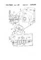
- FIG. 1is a front elevational view of a tool changer mechanism in accordance with an exemplary constructed embodiment of the instant invention.
- FIG. 2is a view taken in the direction of the arrown II of FIG. 1.
- FIG. 3is a view taken substantially along the line III--III of FIG. 1.
- FIG. 4is an enlarged fragmentary view of a turning tool lock.
- FIG. 5is a view taken substantially along the line V--V of FIG. 3.
- FIG. 6is a view taken substantially along the line VI--VI of FIG. 5.
- FIG. 7is a fragmentary view of another embodiment of a turning tool lock.
- FIG. 8is a fragmentary view of yet another embodiment of a turning tool lock.
- a tool change mechanism 10is of a type suitable for use in association with a conventional machining center, for example, a horizontal turning center (not shown).
- the tool changer mechanism 10comprises a bed 12 having ways 14 and 16 thereon for the support of a horizontally movable slide 18.
- the slide 18is controlled by a hydraulic cylinder 20 through a piston rod 22 which is connected to the slide 18.
- the slide 18carries upstanding ways 30 and 32 for the support of a vertically movable arm slide 34.
- the arm slide 34is controlled by a hydraulic cylinder 36 having a piston rod 38 connected to the slide 34.
- rotatable tool changer arm 40is journaled for rotation about a horizontal axis 42 by a hydraulic rotary actuator 44.
- the arm 40is rotatable through an arc of 180° to effect changing of a tool, as will be described.
- the arm 40is provided with wrists 60 and 62 that are rotatable about axes 64 and 66, respectively, relative to the arm 40.
- the wrists 60 and 62are journaled for rotation controlled by hydraulic rotary actuators 68 and 70, respectively.
- the wrists 60 and 62are rotatable through an arc of 90°, to effect one movement in the tool changing sequence, to be described.
- a pair of hands 80 and 81are rotatable about axes 82 and 83 relative to the wrists 60 and 62, under the control of rotary actuators 84 and 85, respectively.
- the hands 81 and 82are provided with sets of fingers 88 and 90, respectively, which are adapted to positively grip a tool, as will be described.
- the pairs of fingers 88 and 90are each provided with pins 92 and 93 that are acceptable in complementary apertures 94 in a tool 96 (see FIG. 4) to effect gripping thereof for purposes of tool change.
- the fingers 88 and 90are provided with pairs of collar gripping jaws 100 and 101, respectively, each of which is of V-shaped arcuate section that is acceptable within a complementary V-shaped groove 102 in a collar 104 (see FIG. 5).
- the collar 104is attachable to a standard boring bar 106 to condition the bar 106 for handling by the tool changer 10.
- a turret 120is provided with a boring bar holder 122 and a cutting tool holder 124.
- the turret 120in the disclosed exemplary constructed embodiment, is indexable through arcs of 60° by a hydraulic cylinder 125 (see FIG. 2), to effect positioning of either the tool 96 or the tool 106 at a cutting station.
- the tool holder 124has a V-shaped recess 126 for the acceptance of a wedge 128.
- the wedge 128is provided with lateral slits 130, 132 and 134 to effect bowing and locking thereof against the tool 96 upon rotation of a locking screw 136 by a powered driver 137. Advancement of the wedge 128 effects locking of the tool 96 against a face 138 of the holder 124.
- the boring bar holder 122has a conical recess 140 for the acceptance of a conical split collar 142.
- the collar 142has an external taper complementary to the taper of the recess 140 in the holder 122.
- the conical collar 142is advanceable in the recess 140 upon rotation of a nut 144 having threads 146 that are complementary to threads 148 on the collar 142.
- Rotation of the nut 144is affected by a worm 150 that is meshed with complementary teeth 152 on the nut 144.
- the worm 150is mounted on a shaft 156 having a drive head 158 for engagement by a powered driver 160. Rotation of the shaft 156 affects rotation of the worm 150 which in turn affects rotation of the nut 144 and advancement or retraction of the conical collar 142 relative to the boring bar tool holder 122.
- a modified wedge 180is usuable to effect locking of the tool 96 in the tool holder 124.
- the wedge 180is provided with lateral slits 182, 184, 186, 188 and 190 that extend from opposite directions to enhance flexibility and compression of the wedge 180 against the angularly related side portion 126 of the holder 124 and the tool 96.
- the wedge 180baises the tool 96 against the side face 138 of the tool holder 124.
- a modified wedge 200effects locking of the tool 96 in the tool holder 124.
- the wedge 200comprises a pair of wedge blocks 202 and 204 that are drawn toward one another up oppositely directed slopes 206 and 208, respectively, to effect wedging of the tool 96 against the edge face 138 of the tool holder 124. Movement of the wedge blocks 202 and 204 toward and away from each other is effected by a screw 210.
- yet another wedge mechanism 218 for effecting locking of the tool 96 in the tool holder 124comprises a pair of hydraulically actuated pistons 220 and 222.
- the pistonsare actuated by hydraulic fluid that is pressurized in a manifold 224 by a piston 226.
- the piston 226is advanced or retracted relative to a threaded nut 228 by rotation of a screw 230.
- the screw 230is rotated by the complementary driver 137. Pressurization of the fluid within the manifold 224 effects advancement of the pistons 220 and 222 against the tool 96 to bias the tool 96 against the edge face 138 of the tool holder 124.
- the tool changer mechanism 10has picked up a tool 96 from a tool magazine 240, the pins 93 on the fingers 90 having been accepted in the complementary apertures 94 in the tool 96. It is to be noted that the pairs of fingers 88 and 90 are spread apart and pulled together by a pneumatic actuator disposed internally of the hands 80 and 82 thereby to effect gripping or release of the tool 96.
- the slide 18is first advanced to the left, as seen in FIG. 1 of the drawings, by energization of the hydraulic cylinder 20.
- the slide 18moves the arm 40 to the left, the pins 92 being accepted in the complementary apertures 94 in the tool 96.
- the power screwdriver 137moves downwardly to effect rotation of the screw 136 which retracts the wedge 128 upwardly freeing the tool 96 for withdrawal from the tool holder 124.
- the slide 118is returned to the position shown in FIG. 1. Thereafter, the arm 40 is rotated 180° bringing the replacement tool 96 into alignment with the tool holder 124 in the turret 120. Mounting of the new tool 96 in the tool holder 124 is accomplished by moving the slide 18.
- the turning toolsare provided with two drilled and chamfered holes to accept the tool changer fingers.
- the boring toolsare provided with a presettable collar having a "V" section in the radial flange thereof.
- the tool changer 10is hydraulically and air operated and controlled by, for example, a Texas Instrument programmable logic controller.
- the changercomprises horizontally and vertically movable slides, and an arm with a hand at each end with fingers and grippers to pick up both boring and turning tools.
- the finger roll, wrist roll, and arm index movementsare actuated by hydraulic rotary actuators and the finger gripping action is air operated.
- a hex turret assemblyis equipped with one boring bar holder and one turning tool holder.
- a hydraulic cylinderpositions the turret and proper holder as required for tool change.
- a magazineholds a replacement boring bar and a turning tool, a hydraulic cylinder positioning the proper tool when a tool change is made.
- the automatic tool lock-unlock mechanismconsists of two air driven nutrunner torque motors mounted on guide rails and delivered to position by a hydraulic cylinder. Each torque motor is set to provide the proper locking torque for both types of tools. Several types of locking mechanisms are utilized for clamping both the turning and boring tools.
Landscapes
- Engineering & Computer Science (AREA)
- Mechanical Engineering (AREA)
- Automatic Tool Replacement In Machine Tools (AREA)
Abstract
Description
Claims (16)
Applications Claiming Priority (1)
| Application Number | Priority Date | Filing Date | Title |
|---|---|---|---|
| PCT/US1982/001216WO1984000915A1 (en) | 1982-09-07 | 1982-09-07 | Tool changer mechanism for machining centers |
Publications (1)
| Publication Number | Publication Date |
|---|---|
| US4654955Atrue US4654955A (en) | 1987-04-07 |
Family
ID=22168181
Family Applications (1)
| Application Number | Title | Priority Date | Filing Date |
|---|---|---|---|
| US06/524,405Expired - Fee RelatedUS4654955A (en) | 1982-09-07 | 1982-09-07 | Tool changer mechanism for machining centers |
Country Status (2)
| Country | Link |
|---|---|
| US (1) | US4654955A (en) |
| WO (1) | WO1984000915A1 (en) |
Cited By (12)
| Publication number | Priority date | Publication date | Assignee | Title |
|---|---|---|---|---|
| US4701994A (en)* | 1985-09-20 | 1987-10-27 | Kabushiki Kaisha Toshiba | Automatic tool assembly apparatus |
| US4713875A (en)* | 1985-11-25 | 1987-12-22 | Heyligenstaedt & Comp. Werkzeugmaschinenfabrik Gmbh | Tool changer |
| US4778331A (en)* | 1986-10-11 | 1988-10-18 | Mecs Corporation | Carrier system for silicon wafer |
| US4988252A (en)* | 1987-07-21 | 1991-01-29 | Murata Kikai Kabushiki Kaisha | Apparatus for supplying packages to a warper creel |
| US5374888A (en)* | 1991-09-05 | 1994-12-20 | Tokyo Electron Kabushiki Kaisha | Electrical characteristics measurement method and measurement apparatus therefor |
| US5774963A (en)* | 1996-09-20 | 1998-07-07 | Globe Products Inc. | Armature manufacturing lines and armature transfer apparatus |
| US6024526A (en)* | 1995-10-20 | 2000-02-15 | Aesop, Inc. | Integrated prober, handler and tester for semiconductor components |
| US20050076757A1 (en)* | 2003-10-03 | 2005-04-14 | Tsugami Corporation (A Japanese Corporation) | Lathe |
| US20050235788A1 (en)* | 2004-04-21 | 2005-10-27 | Alfred H. Shutte Gmbh & Co. Kg | Lathe, in particular multi-spindle automatic lathe |
| US20060010681A1 (en)* | 2004-07-15 | 2006-01-19 | Maschinenfabrik Berthold Hermle Ag | Workpiece changer for machining machines |
| US20140159323A1 (en)* | 2011-08-16 | 2014-06-12 | Gühring Ohg | Chuck for a ball-nose milling cutter |
| CN116251970A (en)* | 2023-02-22 | 2023-06-13 | 上海百琪迈科技(集团)有限公司 | Tool changing structure and cutting device |
Families Citing this family (4)
| Publication number | Priority date | Publication date | Assignee | Title |
|---|---|---|---|---|
| US4922777A (en)* | 1986-09-05 | 1990-05-08 | Contour Saws, Inc. | Band saw for cutting shaped pieces of bar stock |
| US4926728A (en)* | 1986-09-05 | 1990-05-22 | Contour Saws, Inc. | Band saw for cutting shaped pieces of bar stock |
| US4938490A (en)* | 1987-08-27 | 1990-07-03 | Gte Valenite Corporation | Drawback collet |
| US5716310A (en)* | 1995-11-01 | 1998-02-10 | Excellon Automation Company | Tool change apparatus |
Citations (4)
| Publication number | Priority date | Publication date | Assignee | Title |
|---|---|---|---|---|
| US1886224A (en)* | 1931-12-05 | 1932-11-01 | Joseph M Redinger | Cone chuck |
| US3628404A (en)* | 1968-05-17 | 1971-12-21 | Dunlop Co Ltd | Machine tools |
| US3667114A (en)* | 1969-10-02 | 1972-06-06 | Sfm Corp | Tool changing and transfer mechanism |
| US4055095A (en)* | 1975-03-27 | 1977-10-25 | Georg Fischer Aktiengesellschaft | Tool changing device for a lathe |
Family Cites Families (5)
| Publication number | Priority date | Publication date | Assignee | Title |
|---|---|---|---|---|
| US3256600A (en)* | 1963-04-23 | 1966-06-21 | Sundstrand Corp | Tool changing mechanism |
| US3327386A (en)* | 1965-12-27 | 1967-06-27 | De Vlieg Machine Co | Tool handling mechanism and tool for use therewith |
| DE2630857A1 (en)* | 1976-07-09 | 1978-01-12 | Volkswagenwerk Ag | HANDLING MACHINE |
| JPS5341896A (en)* | 1976-09-29 | 1978-04-15 | Toshiba Machine Co Ltd | Tool storaging magazine |
| SU721251A1 (en)* | 1977-03-05 | 1980-03-15 | Предприятие П/Я Р-6564 | Cutting tool holder |
- 1982
- 1982-09-07USUS06/524,405patent/US4654955A/ennot_activeExpired - Fee Related
- 1982-09-07WOPCT/US1982/001216patent/WO1984000915A1/enunknown
Patent Citations (4)
| Publication number | Priority date | Publication date | Assignee | Title |
|---|---|---|---|---|
| US1886224A (en)* | 1931-12-05 | 1932-11-01 | Joseph M Redinger | Cone chuck |
| US3628404A (en)* | 1968-05-17 | 1971-12-21 | Dunlop Co Ltd | Machine tools |
| US3667114A (en)* | 1969-10-02 | 1972-06-06 | Sfm Corp | Tool changing and transfer mechanism |
| US4055095A (en)* | 1975-03-27 | 1977-10-25 | Georg Fischer Aktiengesellschaft | Tool changing device for a lathe |
Cited By (17)
| Publication number | Priority date | Publication date | Assignee | Title |
|---|---|---|---|---|
| US4701994A (en)* | 1985-09-20 | 1987-10-27 | Kabushiki Kaisha Toshiba | Automatic tool assembly apparatus |
| US4713875A (en)* | 1985-11-25 | 1987-12-22 | Heyligenstaedt & Comp. Werkzeugmaschinenfabrik Gmbh | Tool changer |
| US4778331A (en)* | 1986-10-11 | 1988-10-18 | Mecs Corporation | Carrier system for silicon wafer |
| US4988252A (en)* | 1987-07-21 | 1991-01-29 | Murata Kikai Kabushiki Kaisha | Apparatus for supplying packages to a warper creel |
| US5374888A (en)* | 1991-09-05 | 1994-12-20 | Tokyo Electron Kabushiki Kaisha | Electrical characteristics measurement method and measurement apparatus therefor |
| US6024526A (en)* | 1995-10-20 | 2000-02-15 | Aesop, Inc. | Integrated prober, handler and tester for semiconductor components |
| US5774963A (en)* | 1996-09-20 | 1998-07-07 | Globe Products Inc. | Armature manufacturing lines and armature transfer apparatus |
| US5984080A (en)* | 1996-09-20 | 1999-11-16 | Globe Products Inc. | Armature transfer apparatus |
| US20050076757A1 (en)* | 2003-10-03 | 2005-04-14 | Tsugami Corporation (A Japanese Corporation) | Lathe |
| US7448304B2 (en)* | 2003-10-03 | 2008-11-11 | Tsugami Corporation | Lathe |
| US20050235788A1 (en)* | 2004-04-21 | 2005-10-27 | Alfred H. Shutte Gmbh & Co. Kg | Lathe, in particular multi-spindle automatic lathe |
| US7243583B2 (en)* | 2004-04-21 | 2007-07-17 | Alfred H. Schutte Gmbh & Co. Kg | Lathe, in particular multi-spindle automatic lathe |
| US20060010681A1 (en)* | 2004-07-15 | 2006-01-19 | Maschinenfabrik Berthold Hermle Ag | Workpiece changer for machining machines |
| US7478720B2 (en)* | 2004-07-15 | 2009-01-20 | Maschinenfabrik Berthold Hermle Ag | Workpiece changer for machining machines |
| US20140159323A1 (en)* | 2011-08-16 | 2014-06-12 | Gühring Ohg | Chuck for a ball-nose milling cutter |
| CN116251970A (en)* | 2023-02-22 | 2023-06-13 | 上海百琪迈科技(集团)有限公司 | Tool changing structure and cutting device |
| CN116251970B (en)* | 2023-02-22 | 2024-05-17 | 上海百琪迈科技(集团)有限公司 | Tool changing structure and cutting device |
Also Published As
| Publication number | Publication date |
|---|---|
| WO1984000915A1 (en) | 1984-03-15 |
Similar Documents
| Publication | Publication Date | Title |
|---|---|---|
| US4654955A (en) | Tool changer mechanism for machining centers | |
| EP1046461B1 (en) | Universal machine tool | |
| US5372568A (en) | Machine tool with automatic tool changer, having mechanism for utilizing relative movements of tool and tool changing gripper to clamp and unclamp the tool | |
| US5815902A (en) | Rotary transfer machine | |
| GB2070473A (en) | Tooling attachment with an exchangeable cutting tool | |
| JPH04269137A (en) | Multi-tasking machine tools | |
| US4827815A (en) | Hollow-spindle method of machining a short-length workpiece | |
| US4577389A (en) | Automatic tool changer | |
| EP0174799A2 (en) | Machine tools, in particular grinding machines with apparatus for changing grinding wheel tools and workpieces | |
| US4641413A (en) | Tool changer | |
| US4612690A (en) | Multiple spindle machine tool | |
| EP0895825A1 (en) | Apparatus for centering | |
| GB2025275A (en) | Automatic changing of tools in gear-hobbing machines | |
| JPS6218306B2 (en) | ||
| GB2101028A (en) | Tool changing mechanism | |
| JPH06285751A (en) | 3-axis numerical control machine tool with turn head | |
| EP0089373A4 (en) | Machine tool attachment and method of use thereof. | |
| US5735029A (en) | Flexible arbor mill machine | |
| DE3418893A1 (en) | Method and device for loading and unloading workpieces on a machine tool | |
| CN221020145U (en) | Rotary reversing milling device | |
| CN217890306U (en) | Automatic tool changing rack of numerical control machine tool | |
| JPS58165904A (en) | Automatic multi-working piece lathe machine | |
| SU1166966A1 (en) | Automatic machine for drilling,bevel-reaming and thread-cutting | |
| JPS59219102A (en) | Parts gripping part supported by tarret for lathe machine | |
| SU1687381A2 (en) | Device for cutting thin-walled tubes |
Legal Events
| Date | Code | Title | Description |
|---|---|---|---|
| AS | Assignment | Owner name:VALERON CORPORATION, THE, TROY, MICHIGAN A CORP OF Free format text:ASSIGNMENT OF ASSIGNORS INTEREST.;ASSIGNOR:MATHIE, GERALD W.;REEL/FRAME:004268/0148 Effective date:19821108 Owner name:VALERON CORPORATION, THE,MICHIGAN Free format text:ASSIGNMENT OF ASSIGNORS INTEREST;ASSIGNOR:MATHIE, GERALD W.;REEL/FRAME:004268/0148 Effective date:19821108 | |
| FPAY | Fee payment | Year of fee payment:4 | |
| AS | Assignment | Owner name:BANKERS TRUST COMPANY, NEW YORK Free format text:SECURITY INTEREST;ASSIGNOR:GTE VALENITE CORPORATION;REEL/FRAME:006498/0021 Effective date:19930201 | |
| FPAY | Fee payment | Year of fee payment:8 | |
| FEPP | Fee payment procedure | Free format text:PAYOR NUMBER ASSIGNED (ORIGINAL EVENT CODE: ASPN); ENTITY STATUS OF PATENT OWNER: LARGE ENTITY | |
| REMI | Maintenance fee reminder mailed | ||
| LAPS | Lapse for failure to pay maintenance fees | ||
| FP | Lapsed due to failure to pay maintenance fee | Effective date:19990407 | |
| STCH | Information on status: patent discontinuation | Free format text:PATENT EXPIRED DUE TO NONPAYMENT OF MAINTENANCE FEES UNDER 37 CFR 1.362 |