US4653880A - Reflective beam splitting objective - Google Patents
Reflective beam splitting objectiveDownload PDFInfo
- Publication number
- US4653880A US4653880AUS06/707,231US70723185AUS4653880AUS 4653880 AUS4653880 AUS 4653880AUS 70723185 AUS70723185 AUS 70723185AUS 4653880 AUS4653880 AUS 4653880A
- Authority
- US
- United States
- Prior art keywords
- mirror
- image plane
- optical axis
- primary
- intercepting
- Prior art date
- Legal status (The legal status is an assumption and is not a legal conclusion. Google has not performed a legal analysis and makes no representation as to the accuracy of the status listed.)
- Expired - Lifetime
Links
- 230000003287optical effectEffects0.000claimsdescription54
- 238000000926separation methodMethods0.000claims1
- 238000004566IR spectroscopyMethods0.000abstractdescription2
- 238000000034methodMethods0.000description5
- 230000004075alterationEffects0.000description2
- 238000013459approachMethods0.000description2
- 238000003384imaging methodMethods0.000description2
- 238000002310reflectometryMethods0.000description2
- 229910001220stainless steelInorganic materials0.000description2
- 239000010935stainless steelSubstances0.000description2
- 230000000007visual effectEffects0.000description2
- 238000004971IR microspectroscopyMethods0.000description1
- 230000001154acute effectEffects0.000description1
- 229910052782aluminiumInorganic materials0.000description1
- XAGFODPZIPBFFR-UHFFFAOYSA-NaluminiumChemical compound[Al]XAGFODPZIPBFFR-UHFFFAOYSA-N0.000description1
- 230000002238attenuated effectEffects0.000description1
- 238000010276constructionMethods0.000description1
- 230000007423decreaseEffects0.000description1
- -1e.g.Substances0.000description1
- 239000011521glassSubstances0.000description1
- 238000002329infrared spectrumMethods0.000description1
- 238000004519manufacturing processMethods0.000description1
- 229910052751metalInorganic materials0.000description1
- 239000002184metalSubstances0.000description1
- 230000002441reversible effectEffects0.000description1
- 238000011179visual inspectionMethods0.000description1
Images

Classifications
- G—PHYSICS
- G02—OPTICS
- G02B—OPTICAL ELEMENTS, SYSTEMS OR APPARATUS
- G02B21/00—Microscopes
- G02B21/02—Objectives
- G02B21/04—Objectives involving mirrors
- G—PHYSICS
- G01—MEASURING; TESTING
- G01N—INVESTIGATING OR ANALYSING MATERIALS BY DETERMINING THEIR CHEMICAL OR PHYSICAL PROPERTIES
- G01N21/00—Investigating or analysing materials by the use of optical means, i.e. using sub-millimetre waves, infrared, visible or ultraviolet light
- G01N21/17—Systems in which incident light is modified in accordance with the properties of the material investigated
- G01N21/47—Scattering, i.e. diffuse reflection
- G01N21/4738—Diffuse reflection, e.g. also for testing fluids, fibrous materials
- G01N21/474—Details of optical heads therefor, e.g. using optical fibres
- G—PHYSICS
- G02—OPTICS
- G02B—OPTICAL ELEMENTS, SYSTEMS OR APPARATUS
- G02B17/00—Systems with reflecting surfaces, with or without refracting elements
- G02B17/02—Catoptric systems, e.g. image erecting and reversing system
- G02B17/06—Catoptric systems, e.g. image erecting and reversing system using mirrors only, i.e. having only one curved mirror
- G02B17/0605—Catoptric systems, e.g. image erecting and reversing system using mirrors only, i.e. having only one curved mirror using two curved mirrors
- G02B17/061—Catoptric systems, e.g. image erecting and reversing system using mirrors only, i.e. having only one curved mirror using two curved mirrors on-axis systems with at least one of the mirrors having a central aperture
- G—PHYSICS
- G02—OPTICS
- G02B—OPTICAL ELEMENTS, SYSTEMS OR APPARATUS
- G02B21/00—Microscopes
- G02B21/06—Means for illuminating specimens
Definitions
- This inventionrelates to a reflective beam splitting objective optical system for redirecting an energy beam that approaches the system at an angle to its optical axis or along the optical axis from either direction.
- a beam splitteremploying a partially reflective mirror that redirects the beam at substantially a right angle into a focusing system and then to the sample which then transmits part of a reflected beam back through the focusing system, beam splitter and onto a detector.
- a beam splitter of this typeis theoretically limited to an efficiency of 25% because half of the input beam is lost on the initial reflection and half of the remaining beam is lost when the beam is transmitted through the beam splitter.
- This type of beam splitteralso may introduce chromatic aberrations into the reflected beam.
- the refractive beam splitterhowever, has the advantage of having a very simple construction.
- Another means for splitting an input energy beaminvolves off-axis paraboloids, ellipsoids or spherical mirrors.
- These off-axis systemshave means for directing the beam to a focusing mirror which focuses the beam onto a sample. Energy reflected from the sample is focused by a second mirror and directed to a detector through whatever optical arrangement is chosen.
- These systemshave the disadvantage of introducing substantial distortions of the visual image, a phenomenon that is particularly troublesome at high magnifications.
- Off-axis systemsare also not suitable for applications where it is desirable to mask part of the image being sent to the detector.
- complex mirror arrangementsmay be created that illuminate the sample and recreate an undistorted image of the sample that may be used by a detector.
- These complex mirror arrangementswhile producing an adequate optical path, involve considerable mechanical complexity and expense in manufacture.
- complex systemsinvolve complex problems of alignment of the optical components.
- these systemsare generally not compact, making for a system that is cumbersome, complex and difficult to maintain in optical alignment.
- Present beam splittersgenerally do not provide an economical and accurate method of redirecting an image beam at an angle to the optical axis of an infrared microscopic imaging system. This problem is particularly acute in connection with obtaining infrared spectra of extremely small size samples where it is necessary to mask the image received by the detector.
- the present inventioncomprises a reflective beam splitting apparatus and process, wherein an energy beam intercepting mirror is positioned to divide the optical axis of a Cassegrain or similar reflecting objective.
- the intercepting mirroris positioned a sufficient distance from a secondary mirror so as not to vignette an energy beam directed from the secondary mirror to a primary mirror and sufficiently close to the secondary mirror so as not to unevenly attenuate an image formed behind the primary mirror.
- the inventioncomprises a procedure for directing an input energy beam at an angle substantially perpendicular to the optical axis of the system, wherein the beam is directed onto the axis of the system by an intercepting mirror which reflects the energy to a portion of the secondary mirror area then onto the primary mirror which directs the energy to the sample.
- the inventionalso comprises a procedure for inputting an energy beam substantially on the optical axis and using the intercepting mirror to divide the resulting image into a first component that the Cassegrain optics focuses on-axis to the system and a second component that is focused at an angle to the optical axis each component forming an image of the entire sample image.
- the present inventionfocuses all points on a sample located at the respective image planes, thus enabling visual inspection of a sample to determine from which areas energy may be received by one or more detectors.
- the inventionhas proven to have particular utility in the field of infrared microscopy.
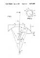
- FIG. 1shows a reflective beam splitting objective according to the present invention
- FIG. 2is a top perspective of the intercepting mirror and secondary mirror shown in FIG. 1;
- FIG. 3is an illustration of a reflecting objective that is useful for understanding the present invention.
- FIG. 4shows a partially transmitting/partially reflecting beam splitter.
- the optical arrangement constructed in accordance with a preferred embodiment of the present inventionhas an intercepting mirror 10 with a reflective surface 10a positioned above a secondary mirror 12 having a reflective surface 13. Positioned over a first portion 12a of secondary mirror 12 is an intercepting mirror 10 having a first edge 14 extending beyond an edge of secondary mirror 12 for example by a distance indicated by 15 in FIG. 2. A second side edge 16 of intercepting mirror 10 is aligned over secondary mirror 12 so as to form a great diameter on mirror 12 as shown in FIG. 2. The intercepting mirror 10 is positioned in between a primary mirror 22 having a reflective surface 22a and secondary mirror 12. A lower edge 18 of mirror 10 is separated from the uppermost surface of secondary mirror 12 by a distance 20. Mirror surfaces 13 and 22a are substantially concentric except for minor adjustments for aberrations.
- the position of the intercepting mirroris determined by the following considerations. If the intercepting mirror is close to third image plane 36, the mirror attenuates part of the image; therefore, to maintain an evenly illuminated image on third image plane 36, intercepting mirror 10 should be as far from the image plane as possible. In the optical arrangement shown in FIG. 1, this design consideration, by itself, would ideally place the intercepting mirror as close as physically possible to secondary mirror 12. However, placing the intercepting mirror too close to the secondary mirror places first edge 14 of mirror 10 in the path of a portion of the energy reflected between first portion 12a of mirror 12 and the primary mirror 22 causing edge 14 to vignette the beam.
- mirror 10should be positioned off axis to neither unevenly attenuate the image on image plane 36 or vignette ray 105.
- the most preferred position for mirror 10has the lower edge 18 of mirror 10 separated by a distance 20 that is the smallest distance necessary to prevent edge 14 from vignetting ray 105.
- one-half of a symmetric input beam 200would be directed along the optical axis 250 of the system to secondary mirror 12.
- the input beamwould be focused by the Cassegrain optics onto second image plane 30 as in the present invention.
- the mirrorswould image the sample back to the source at third image plane plane 36.
- one-half of the imagemust fall on the emitter 201 of beam 200. Therefore, employing a Cassegrain mirror arrangement without the intercepting mirror requires losing one-half of the image field.
- the present inventionemploys intercepting mirror 10 to rotate the source of input energy so that the input beam is roughly perpendicular to the optical axis 21.
- the intercepting mirrordirects the input beam from first image plane 236 to the secondary mirror from where the beam is reflected to the primary mirror which focuses the light to form an image at second image plane 30 on the sample which is in turn focused to an image behind focus 34 at third image plane 36 as shown in FIG. 1.
- the optical arrangement of the present inventiondoes not require source 201 to block out half of the image of the sample at third image plane 36 because source 201 is no longer positioned on the sample plane. Therefore, all points of the sample are imaged on third image plane 36.
- the present inventionhas the potential to obtain a 100% increase in efficiency over a conventional refractive beam splitter of the general type shown in FIG. 4.
- a symmetric input beam 120falls on the refractive beam splitter 122.
- a part of the beam indicated by 121passes through the refractive beam splitter and is lost from the system.
- Another partis reflected down to sample plane 130 through a reflecting objective 131.
- the energy reflected back from the sample through the reflecting objectiveagain encounters beam splitter 122 which reflects part of the energy from the sample plane to the input source. At most only one quarter of the input energy may reach focus 34 if the refractive beam splitter 122 transmits and reflects exactly one-half of the incident energy.
- refractive beam splitter 122reflects or transmits more than one-half of the incident energy.
- a conventional refractive beam splittermay obtain efficiencies of only approximately 20% or less. This is especially true for beam splitters used with infrared energy beams. This level of efficiency is unacceptable for many applications.
- the beam splitter of the present inventionneed lose only one-half of the energy contained in input beam 100. This energy is lost because secondary mirror 12 may reflect only one-half of a symmetrical beam; the other half of the beam must be lost.
- the efficiency of the systemalso depends on the reflectivity of the sample. If the sample at second image plane at second image plane 30 is perfectly reflective, i.e., a mirror, the efficiency of the system approaches 50%, i.e., all the energy input into the objective and reflectivity redirected by the intercepting mirror 10 reaches focus 34.
- the reflective beam splitting objective of the present inventionobtains an efficiency of only 25% of the collectable energy, or an efficiency that is equal to the best possible efficiency obtainable with a conventional refractive beam splitter arrangement of the type shown in FIG. 4.
- the reflective beam splitter apparatus of the present inventionmay have an input beam 110 focused at second image plane 30 along the optical axis. Energy passing through the second image plane fills primary mirror 22. Substantially half of the energy from mirror 22 is reflected from secondary mirror 12 to intercepting mirror 10 and focused off the optical axis 21 of the system at first image plane 231. Substantially half of the energy collected by the primary mirror reaches third image plane 34 on the optical axis of the system.
- the optical arrangement of the present inventionsplits input beam 110 into two components and images each component.
- Each image of the beam splittercontains information from the entire second image plane 30 so long as intercepting mirror 10 is not close to third image plane plane 36 and edge 14 does not vignette ray 105.
- the input energy beamalso could be sourced at the third image plane 36 and reflect an image from the sample to first image plane 236, in reverse to that illustrated.
- the optical arrangement according to the present inventionalso contemplates placing the intercepting mirror between the secondary and primary mirrors so as to make the reflective beam splitting objective an integral unit.
- This arrangementhas proven to have particular utility for obtaining a stable aligned optical configuration. It has been found that the alignment of the optical component is particularly critical to obtaining a high efficiency when the intercepting mirror is at its minimum distance from the secondary mirror.
- the secondary mirrormay be made of glass while the intercepting mirror and the primary mirror are preferably made of metal, e.g., stainless steel, which may be coated with aluminum.
- the stainless steelenables holes to be placed into the base of the mirror so as to provide known reference points for relating the surface of the mirror to the optical path and structural components. This mechanical assembly greatly simplifies initial optical alignment and serves to better maintain the optical alignment.
- the reflecting beam splitting objective of the present inventionhas a smaller size than can be obtained by placing the intercepting mirror elsewhere, such as behind the primary mirror. Also, vignetting of ray 105 may be reduced by making first edge 14 as sharp as possible so that jagged edges do not protrude into the path of the ray.
- a Cassegrain arrangement of the mirrors in the systemproduce an optimum reflecting objective.
- other lens arrangementscould be used.
- a pure mirror arrangement, such as disclosed above,has particular utility for use in infrared spectroscopy.
- Other optical arrangements, such as a Maksutov optical arrangement,could be used.
Landscapes
- Physics & Mathematics (AREA)
- General Physics & Mathematics (AREA)
- Optics & Photonics (AREA)
- Chemical & Material Sciences (AREA)
- Analytical Chemistry (AREA)
- Life Sciences & Earth Sciences (AREA)
- Health & Medical Sciences (AREA)
- Biochemistry (AREA)
- General Health & Medical Sciences (AREA)
- Immunology (AREA)
- Pathology (AREA)
- Microscoopes, Condenser (AREA)
- Lenses (AREA)
- Spectrometry And Color Measurement (AREA)
Abstract
Description
Claims (8)
Priority Applications (5)
| Application Number | Priority Date | Filing Date | Title |
|---|---|---|---|
| US06/707,231US4653880A (en) | 1985-03-01 | 1985-03-01 | Reflective beam splitting objective |
| DE8686301472TDE3685359D1 (en) | 1985-03-01 | 1986-02-28 | MIRROR LENS ARRANGEMENT. |
| JP61043913AJPS61212733A (en) | 1985-03-01 | 1986-02-28 | Method of orienting beam and reflected-beam spectral device |
| EP86301472AEP0196789B1 (en) | 1985-03-01 | 1986-02-28 | Reflective objective apparatus |
| US07/302,112US4878747A (en) | 1985-03-01 | 1989-01-24 | Aperture image beam splitter |
Applications Claiming Priority (1)
| Application Number | Priority Date | Filing Date | Title |
|---|---|---|---|
| US06/707,231US4653880A (en) | 1985-03-01 | 1985-03-01 | Reflective beam splitting objective |
Related Child Applications (1)
| Application Number | Title | Priority Date | Filing Date |
|---|---|---|---|
| US1358487AContinuation-In-Part | 1985-03-01 | 1987-02-11 |
Publications (1)
| Publication Number | Publication Date |
|---|---|
| US4653880Atrue US4653880A (en) | 1987-03-31 |
Family
ID=24840878
Family Applications (1)
| Application Number | Title | Priority Date | Filing Date |
|---|---|---|---|
| US06/707,231Expired - LifetimeUS4653880A (en) | 1985-03-01 | 1985-03-01 | Reflective beam splitting objective |
Country Status (4)
| Country | Link |
|---|---|
| US (1) | US4653880A (en) |
| EP (1) | EP0196789B1 (en) |
| JP (1) | JPS61212733A (en) |
| DE (1) | DE3685359D1 (en) |
Cited By (63)
| Publication number | Priority date | Publication date | Assignee | Title |
|---|---|---|---|---|
| US4786169A (en)* | 1985-08-08 | 1988-11-22 | Nicolet Instrument Corporation | Optical analytical instrument for testing the transmission and reflection of a sample |
| US4810077A (en)* | 1986-02-13 | 1989-03-07 | Spectra-Tech, Inc. | Grazing angle microscope |
| US4863253A (en)* | 1987-09-25 | 1989-09-05 | Spectra-Tech, Inc. | High magnification reflecting microscope objective having a dual magnification mode and zoom magnification capability |
| US4877960A (en)* | 1987-02-17 | 1989-10-31 | Spectra-Tech, Inc. | Microscope having dual remote image masking |
| US4878747A (en)* | 1985-03-01 | 1989-11-07 | Spectra-Tech, Inc. | Aperture image beam splitter |
| US5011243A (en)* | 1986-09-16 | 1991-04-30 | Laser Precision Corporation | Reflectance infrared microscope having high radiation throughput |
| US5016995A (en)* | 1988-04-28 | 1991-05-21 | Pullen V William J | Radiation gathering and focusing apparatus and devices |
| US5136413A (en)* | 1990-11-05 | 1992-08-04 | Litel Instruments | Imaging and illumination system with aspherization and aberration correction by phase steps |
| US5163936A (en)* | 1991-01-22 | 1992-11-17 | Reliant Laser Corp. | Endoscopic mirror laser beam delivery system and method for controlling alignment |
| US5239409A (en)* | 1986-09-16 | 1993-08-24 | Research-Cottrell Technologies, Inc. | Reflectance infrared microscope having high radiation throughput |
| US5266795A (en)* | 1991-11-01 | 1993-11-30 | The United States Of America As Represented By The Administrator Of The National Aeronautics And Space Administration | Wide-angle imaging system with fiberoptic components providing angle-dependent virtual material stops |
| US6157041A (en)* | 1998-10-13 | 2000-12-05 | Rio Grande Medical Technologies, Inc. | Methods and apparatus for tailoring spectroscopic calibration models |
| US6240306B1 (en) | 1995-08-09 | 2001-05-29 | Rio Grande Medical Technologies, Inc. | Method and apparatus for non-invasive blood analyte measurement with fluid compartment equilibration |
| US6441388B1 (en) | 1998-10-13 | 2002-08-27 | Rio Grande Medical Technologies, Inc. | Methods and apparatus for spectroscopic calibration model transfer |
| US20020171834A1 (en)* | 2001-04-11 | 2002-11-21 | Rowe Robert K. | Encoded variable filter spectrometer |
| US20020183624A1 (en)* | 2001-06-05 | 2002-12-05 | Rio Grande Medical Technologies, Inc. | Apparatus and method of biometric determination using specialized optical spectroscopy systems |
| US6560352B2 (en) | 1999-10-08 | 2003-05-06 | Lumidigm, Inc. | Apparatus and method of biometric identification or verification of individuals using optical spectroscopy |
| US6574490B2 (en) | 2001-04-11 | 2003-06-03 | Rio Grande Medical Technologies, Inc. | System for non-invasive measurement of glucose in humans |
| US6628809B1 (en) | 1999-10-08 | 2003-09-30 | Lumidigm, Inc. | Apparatus and method for identification of individuals by near-infrared spectrum |
| US6654125B2 (en) | 2002-04-04 | 2003-11-25 | Inlight Solutions, Inc | Method and apparatus for optical spectroscopy incorporating a vertical cavity surface emitting laser (VCSEL) as an interferometer reference |
| US20040033618A1 (en)* | 1998-10-13 | 2004-02-19 | Haass Michael J. | Accommodating subject and instrument variations in spectroscopic determinations |
| US6816605B2 (en) | 1999-10-08 | 2004-11-09 | Lumidigm, Inc. | Methods and systems for biometric identification of individuals using linear optical spectroscopy |
| US20040240712A1 (en)* | 2003-04-04 | 2004-12-02 | Lumidigm, Inc. | Multispectral biometric sensor |
| US20050007582A1 (en)* | 2003-07-07 | 2005-01-13 | Lumidigm, Inc. | Methods and apparatus for collection of optical reference measurements for monolithic sensors |
| US6862091B2 (en) | 2001-04-11 | 2005-03-01 | Inlight Solutions, Inc. | Illumination device and method for spectroscopic analysis |
| US6865408B1 (en) | 2001-04-11 | 2005-03-08 | Inlight Solutions, Inc. | System for non-invasive measurement of glucose in humans |
| US20050073690A1 (en)* | 2003-10-03 | 2005-04-07 | Abbink Russell E. | Optical spectroscopy incorporating a vertical cavity surface emitting laser (VCSEL) |
| US20050205667A1 (en)* | 2003-04-04 | 2005-09-22 | Lumidigm, Inc. | Combined total-internal-reflectance and tissue imaging systems and methods |
| US20050265585A1 (en)* | 2004-06-01 | 2005-12-01 | Lumidigm, Inc. | Multispectral liveness determination |
| US20050271258A1 (en)* | 2004-06-01 | 2005-12-08 | Lumidigm, Inc. | Multispectral imaging biometrics |
| US6983176B2 (en) | 2001-04-11 | 2006-01-03 | Rio Grande Medical Technologies, Inc. | Optically similar reference samples and related methods for multivariate calibration models used in optical spectroscopy |
| US20060062438A1 (en)* | 2003-04-04 | 2006-03-23 | Lumidigm, Inc. | Comparative texture analysis of tissue for biometric spoof detection |
| US7027848B2 (en) | 2002-04-04 | 2006-04-11 | Inlight Solutions, Inc. | Apparatus and method for non-invasive spectroscopic measurement of analytes in tissue using a matched reference analyte |
| US7043288B2 (en) | 2002-04-04 | 2006-05-09 | Inlight Solutions, Inc. | Apparatus and method for spectroscopic analysis of tissue to detect diabetes in an individual |
| US20060211928A1 (en)* | 2002-04-04 | 2006-09-21 | Hull Edward L | Determination of a measure of a glycation end-product or disease state using tissue fluorescence preferentially from the dermis |
| US20060244947A1 (en)* | 2005-04-27 | 2006-11-02 | Lumidigm, Inc. | Multispectral Biometric Sensors |
| US20070030475A1 (en)* | 2003-04-04 | 2007-02-08 | Lumidigm, Inc. | White-light spectral biometric sensors |
| US20070197880A1 (en)* | 2002-04-04 | 2007-08-23 | Maynard John D | Determination of a Measure of a Glycation End-Product or Disease State Using Tissue Fluorescence of Various Sites |
| US7263213B2 (en) | 2003-12-11 | 2007-08-28 | Lumidigm, Inc. | Methods and systems for estimation of personal characteristics from biometric measurements |
| US20070265532A1 (en)* | 2002-04-04 | 2007-11-15 | Maynard John D | Determination of a Measure of a Glycation End-Product or Disease State Using a Flexible Probe to Determine Tissue Fluorescence of Various Sites |
| US20070276199A1 (en)* | 2002-04-04 | 2007-11-29 | Ediger Marwood N | Determination of a Measure of a Glycation End-Product or Disease State Using Tissue Fluorescence |
| US7394919B2 (en) | 2004-06-01 | 2008-07-01 | Lumidigm, Inc. | Multispectral biometric imaging |
| US20080192988A1 (en)* | 2006-07-19 | 2008-08-14 | Lumidigm, Inc. | Multibiometric multispectral imager |
| US20080232653A1 (en)* | 2007-03-21 | 2008-09-25 | Lumidigm, Inc. | Biometrics based on locally consistent features |
| US20080298649A1 (en)* | 2004-06-01 | 2008-12-04 | Lumidigm, Inc. | Hygienic biometric sensors |
| US20090046903A1 (en)* | 2007-04-10 | 2009-02-19 | Lumidigm, Inc. | Biometric Detection Using Spatial, Temporal, And/Or Spectral Techniques |
| US7508965B2 (en) | 2004-06-01 | 2009-03-24 | Lumidigm, Inc. | System and method for robust fingerprint acquisition |
| US20090080709A1 (en)* | 2006-07-19 | 2009-03-26 | Lumidigm, Inc. | Whole-Hand Multispectral Biometric Imaging |
| US7545963B2 (en) | 2003-04-04 | 2009-06-09 | Lumidigm, Inc. | Texture-biometrics sensor |
| US20090245591A1 (en)* | 2006-07-19 | 2009-10-01 | Lumidigm, Inc. | Contactless Multispectral Biometric Capture |
| US7620212B1 (en) | 2002-08-13 | 2009-11-17 | Lumidigm, Inc. | Electro-optical sensor |
| US7627151B2 (en) | 2003-04-04 | 2009-12-01 | Lumidigm, Inc. | Systems and methods for improved biometric feature definition |
| US7801339B2 (en) | 2006-07-31 | 2010-09-21 | Lumidigm, Inc. | Biometrics with spatiospectral spoof detection |
| US7804984B2 (en) | 2006-07-31 | 2010-09-28 | Lumidigm, Inc. | Spatial-spectral fingerprint spoof detection |
| US20100246902A1 (en)* | 2009-02-26 | 2010-09-30 | Lumidigm, Inc. | Method and apparatus to combine biometric sensing and other functionality |
| US20110085708A1 (en)* | 2009-08-26 | 2011-04-14 | Lumidigm. Inc. | Multiplexed biometric imaging |
| US20110163163A1 (en)* | 2004-06-01 | 2011-07-07 | Lumidigm, Inc. | Multispectral barcode imaging |
| US8570149B2 (en) | 2010-03-16 | 2013-10-29 | Lumidigm, Inc. | Biometric imaging using an optical adaptive interface |
| JP2014002025A (en)* | 2012-06-18 | 2014-01-09 | Tokyo Institute Of Technology | Object detector |
| US8787630B2 (en) | 2004-08-11 | 2014-07-22 | Lumidigm, Inc. | Multispectral barcode imaging |
| US10481500B2 (en) | 2009-02-12 | 2019-11-19 | Carl Zeiss Smt Gmbh | Imaging optical system and projection exposure installation for microlithography with an imaging optical system of this type |
| WO2020006633A1 (en)* | 2018-07-03 | 2020-01-09 | Global Analyzer Systems Limited | Self-aligned high finesse optical sensor cell |
| CN114878520A (en)* | 2022-06-15 | 2022-08-09 | 光子集成(温州)创新研究院 | Active continuous spectrum remote measuring system |
Families Citing this family (3)
| Publication number | Priority date | Publication date | Assignee | Title |
|---|---|---|---|---|
| JPH02502223A (en)* | 1987-02-11 | 1990-07-19 | スペクトラ‐テック・インコーポレーテッド | aperture image beam splitter |
| FR2649496B1 (en)* | 1989-07-10 | 1992-11-06 | Bertin & Cie | MIRROR STRUCTURE AND MANUFACTURING METHOD THEREOF |
| IL140248A0 (en) | 1998-06-16 | 2002-02-10 | Orbotech Ltd | Illuminator for inspecting substantially flat surfaces |
Citations (16)
| Publication number | Priority date | Publication date | Assignee | Title |
|---|---|---|---|---|
| US2478762A (en)* | 1945-12-28 | 1949-08-09 | Lyle T Johnson | Reflecting microscope |
| US2628529A (en)* | 1948-09-25 | 1953-02-17 | Lawrence E Braymer | Reflecting telescope with auxiliary optical system |
| US2743646A (en)* | 1952-05-17 | 1956-05-01 | John D Strong | Optical instrument having throughand-return light path |
| US3010358A (en)* | 1959-02-19 | 1961-11-28 | Perkin Elmer Corp | Radiation microsampling apparatus |
| CH359783A (en)* | 1958-06-20 | 1962-01-31 | Rueger Ernst A | Photoelectric scanning device for reflection light controls |
| CH402445A (en)* | 1961-05-18 | 1965-11-15 | Hensoldt & Soehne Optik | Lens with telecentric beam path and an aspect ratio of 1: 1 |
| US3251219A (en)* | 1961-07-05 | 1966-05-17 | Siemens Reineger Werke Ag | Transceiving ultrasonic impulses in medical diagnostics |
| US3411852A (en)* | 1963-11-06 | 1968-11-19 | Optical Coating Laboratory Inc | Optical monitoring apparatus which includes a reflector system for focusing light ona sample and for receiving light reflected from the sample |
| US3521943A (en)* | 1966-09-30 | 1970-07-28 | Herman F Kelderman | Apparatus for generating aspheric reflecting surfaces useful for correcting spherical aberration |
| US3858046A (en)* | 1973-06-25 | 1974-12-31 | Hughes Aircraft Co | Catadioptric beamsplitter system |
| US3961179A (en)* | 1975-02-07 | 1976-06-01 | General Dynamics Corporation | Beam directing system having a moveable low mass inertia beam folding optical element |
| US3968362A (en)* | 1975-08-11 | 1976-07-06 | Honeywell Inc. | Optical system for laser doppler homodyne detection |
| DE3208706A1 (en)* | 1981-03-12 | 1982-11-11 | Olympus Optical Co., Ltd., Tokyo | An illuminating system for optical equipment |
| US4395095A (en)* | 1981-05-20 | 1983-07-26 | The United States Of America As Represented By The Secretary Of The Navy | Optical system for infrared tracking |
| SU1095123A1 (en)* | 1983-03-24 | 1984-05-30 | Одесский Ордена Трудового Красного Знамени Государственный Университет Им.И.И.Мечникова | Optical system having scanned field of view |
| EP0116321A2 (en)* | 1983-01-31 | 1984-08-22 | Bruker Analytische Messtechnik GmbH | Infrared spectrometer |
- 1985
- 1985-03-01USUS06/707,231patent/US4653880A/ennot_activeExpired - Lifetime
- 1986
- 1986-02-28EPEP86301472Apatent/EP0196789B1/ennot_activeExpired - Lifetime
- 1986-02-28DEDE8686301472Tpatent/DE3685359D1/ennot_activeExpired - Fee Related
- 1986-02-28JPJP61043913Apatent/JPS61212733A/enactivePending
Patent Citations (17)
| Publication number | Priority date | Publication date | Assignee | Title |
|---|---|---|---|---|
| US2478762A (en)* | 1945-12-28 | 1949-08-09 | Lyle T Johnson | Reflecting microscope |
| US2628529A (en)* | 1948-09-25 | 1953-02-17 | Lawrence E Braymer | Reflecting telescope with auxiliary optical system |
| US2743646A (en)* | 1952-05-17 | 1956-05-01 | John D Strong | Optical instrument having throughand-return light path |
| CH359783A (en)* | 1958-06-20 | 1962-01-31 | Rueger Ernst A | Photoelectric scanning device for reflection light controls |
| US3010358A (en)* | 1959-02-19 | 1961-11-28 | Perkin Elmer Corp | Radiation microsampling apparatus |
| CH402445A (en)* | 1961-05-18 | 1965-11-15 | Hensoldt & Soehne Optik | Lens with telecentric beam path and an aspect ratio of 1: 1 |
| US3251219A (en)* | 1961-07-05 | 1966-05-17 | Siemens Reineger Werke Ag | Transceiving ultrasonic impulses in medical diagnostics |
| US3411852A (en)* | 1963-11-06 | 1968-11-19 | Optical Coating Laboratory Inc | Optical monitoring apparatus which includes a reflector system for focusing light ona sample and for receiving light reflected from the sample |
| US3521943A (en)* | 1966-09-30 | 1970-07-28 | Herman F Kelderman | Apparatus for generating aspheric reflecting surfaces useful for correcting spherical aberration |
| US3858046A (en)* | 1973-06-25 | 1974-12-31 | Hughes Aircraft Co | Catadioptric beamsplitter system |
| US3961179A (en)* | 1975-02-07 | 1976-06-01 | General Dynamics Corporation | Beam directing system having a moveable low mass inertia beam folding optical element |
| US3968362A (en)* | 1975-08-11 | 1976-07-06 | Honeywell Inc. | Optical system for laser doppler homodyne detection |
| DE3208706A1 (en)* | 1981-03-12 | 1982-11-11 | Olympus Optical Co., Ltd., Tokyo | An illuminating system for optical equipment |
| US4395095A (en)* | 1981-05-20 | 1983-07-26 | The United States Of America As Represented By The Secretary Of The Navy | Optical system for infrared tracking |
| EP0116321A2 (en)* | 1983-01-31 | 1984-08-22 | Bruker Analytische Messtechnik GmbH | Infrared spectrometer |
| US4594509A (en)* | 1983-01-31 | 1986-06-10 | Bruker Analytische Messtechnik Gmbh | Infrared spectrometer |
| SU1095123A1 (en)* | 1983-03-24 | 1984-05-30 | Одесский Ордена Трудового Красного Знамени Государственный Университет Им.И.И.Мечникова | Optical system having scanned field of view |
Non-Patent Citations (2)
| Title |
|---|
| K. P. Norris, "A Reflecting Microscope for Infra-Red Absorption Measurements", Aug. 1954, Journal of Scientific Instruments, vol. 31, pp. 284-287, London, GB. |
| K. P. Norris, A Reflecting Microscope for Infra Red Absorption Measurements , Aug. 1954, Journal of Scientific Instruments, vol. 31, pp. 284 287, London, GB.* |
Cited By (113)
| Publication number | Priority date | Publication date | Assignee | Title |
|---|---|---|---|---|
| US4878747A (en)* | 1985-03-01 | 1989-11-07 | Spectra-Tech, Inc. | Aperture image beam splitter |
| US4786169A (en)* | 1985-08-08 | 1988-11-22 | Nicolet Instrument Corporation | Optical analytical instrument for testing the transmission and reflection of a sample |
| US4810077A (en)* | 1986-02-13 | 1989-03-07 | Spectra-Tech, Inc. | Grazing angle microscope |
| US5011243A (en)* | 1986-09-16 | 1991-04-30 | Laser Precision Corporation | Reflectance infrared microscope having high radiation throughput |
| US5239409A (en)* | 1986-09-16 | 1993-08-24 | Research-Cottrell Technologies, Inc. | Reflectance infrared microscope having high radiation throughput |
| US4877960A (en)* | 1987-02-17 | 1989-10-31 | Spectra-Tech, Inc. | Microscope having dual remote image masking |
| US4863253A (en)* | 1987-09-25 | 1989-09-05 | Spectra-Tech, Inc. | High magnification reflecting microscope objective having a dual magnification mode and zoom magnification capability |
| US5016995A (en)* | 1988-04-28 | 1991-05-21 | Pullen V William J | Radiation gathering and focusing apparatus and devices |
| US5136413A (en)* | 1990-11-05 | 1992-08-04 | Litel Instruments | Imaging and illumination system with aspherization and aberration correction by phase steps |
| US5163936A (en)* | 1991-01-22 | 1992-11-17 | Reliant Laser Corp. | Endoscopic mirror laser beam delivery system and method for controlling alignment |
| US5266795A (en)* | 1991-11-01 | 1993-11-30 | The United States Of America As Represented By The Administrator Of The National Aeronautics And Space Administration | Wide-angle imaging system with fiberoptic components providing angle-dependent virtual material stops |
| US5349180A (en)* | 1991-11-01 | 1994-09-20 | The United States Of America As Represented By The Administrator Of The National Aeronautics And Space Administration | Wide field strip-imaging optical system |
| US6240306B1 (en) | 1995-08-09 | 2001-05-29 | Rio Grande Medical Technologies, Inc. | Method and apparatus for non-invasive blood analyte measurement with fluid compartment equilibration |
| US6718189B2 (en) | 1995-08-09 | 2004-04-06 | Rio Grande Medical Technologies, Inc. | Method and apparatus for non-invasive blood analyte measurement with fluid compartment equilibration |
| US9487398B2 (en) | 1997-06-09 | 2016-11-08 | Hid Global Corporation | Apparatus and method of biometric determination using specialized optical spectroscopy systems |
| US20080304712A1 (en)* | 1997-06-09 | 2008-12-11 | Lumidigm, Inc. | Apparatus and method of biometric determination using specialized optical spectroscopy systems |
| US6157041A (en)* | 1998-10-13 | 2000-12-05 | Rio Grande Medical Technologies, Inc. | Methods and apparatus for tailoring spectroscopic calibration models |
| US6441388B1 (en) | 1998-10-13 | 2002-08-27 | Rio Grande Medical Technologies, Inc. | Methods and apparatus for spectroscopic calibration model transfer |
| US6528809B1 (en) | 1998-10-13 | 2003-03-04 | Rio Grande Medical Technologies, Inc. | Methods and apparatus for tailoring spectroscopic calibration models |
| US20040033618A1 (en)* | 1998-10-13 | 2004-02-19 | Haass Michael J. | Accommodating subject and instrument variations in spectroscopic determinations |
| US7098037B2 (en) | 1998-10-13 | 2006-08-29 | Inlight Solutions, Inc. | Accommodating subject and instrument variations in spectroscopic determinations |
| US6816605B2 (en) | 1999-10-08 | 2004-11-09 | Lumidigm, Inc. | Methods and systems for biometric identification of individuals using linear optical spectroscopy |
| US6628809B1 (en) | 1999-10-08 | 2003-09-30 | Lumidigm, Inc. | Apparatus and method for identification of individuals by near-infrared spectrum |
| US6560352B2 (en) | 1999-10-08 | 2003-05-06 | Lumidigm, Inc. | Apparatus and method of biometric identification or verification of individuals using optical spectroscopy |
| US7203345B2 (en) | 1999-10-08 | 2007-04-10 | Lumidigm, Inc. | Apparatus and method for identification of individuals by near-infrared spectrum |
| US6574490B2 (en) | 2001-04-11 | 2003-06-03 | Rio Grande Medical Technologies, Inc. | System for non-invasive measurement of glucose in humans |
| US6862091B2 (en) | 2001-04-11 | 2005-03-01 | Inlight Solutions, Inc. | Illumination device and method for spectroscopic analysis |
| US6865408B1 (en) | 2001-04-11 | 2005-03-08 | Inlight Solutions, Inc. | System for non-invasive measurement of glucose in humans |
| US20020171834A1 (en)* | 2001-04-11 | 2002-11-21 | Rowe Robert K. | Encoded variable filter spectrometer |
| US7126682B2 (en) | 2001-04-11 | 2006-10-24 | Rio Grande Medical Technologies, Inc. | Encoded variable filter spectrometer |
| US6983176B2 (en) | 2001-04-11 | 2006-01-03 | Rio Grande Medical Technologies, Inc. | Optically similar reference samples and related methods for multivariate calibration models used in optical spectroscopy |
| US7890158B2 (en) | 2001-06-05 | 2011-02-15 | Lumidigm, Inc. | Apparatus and method of biometric determination using specialized optical spectroscopy systems |
| US20020183624A1 (en)* | 2001-06-05 | 2002-12-05 | Rio Grande Medical Technologies, Inc. | Apparatus and method of biometric determination using specialized optical spectroscopy systems |
| US7613504B2 (en) | 2001-06-05 | 2009-11-03 | Lumidigm, Inc. | Spectroscopic cross-channel method and apparatus for improved optical measurements of tissue |
| US20060211928A1 (en)* | 2002-04-04 | 2006-09-21 | Hull Edward L | Determination of a measure of a glycation end-product or disease state using tissue fluorescence preferentially from the dermis |
| US20070088205A1 (en)* | 2002-04-04 | 2007-04-19 | Hull Edward L | Determination of a Measure of a Glycation End-Product or Disease State Using Tissue Fluorescence |
| US8121671B2 (en) | 2002-04-04 | 2012-02-21 | Veralight, Inc. | Determination of a measure of a glycation end-product or disease state using tissue fluorescence preferentially from the dermis |
| US7027848B2 (en) | 2002-04-04 | 2006-04-11 | Inlight Solutions, Inc. | Apparatus and method for non-invasive spectroscopic measurement of analytes in tissue using a matched reference analyte |
| US7043288B2 (en) | 2002-04-04 | 2006-05-09 | Inlight Solutions, Inc. | Apparatus and method for spectroscopic analysis of tissue to detect diabetes in an individual |
| US8131332B2 (en) | 2002-04-04 | 2012-03-06 | Veralight, Inc. | Determination of a measure of a glycation end-product or disease state using tissue fluorescence of various sites |
| US6654125B2 (en) | 2002-04-04 | 2003-11-25 | Inlight Solutions, Inc | Method and apparatus for optical spectroscopy incorporating a vertical cavity surface emitting laser (VCSEL) as an interferometer reference |
| US8140147B2 (en) | 2002-04-04 | 2012-03-20 | Veralight, Inc. | Determination of a measure of a glycation end-product or disease state using a flexible probe to determine tissue fluorescence of various sites |
| US8078243B2 (en) | 2002-04-04 | 2011-12-13 | Veralight, Inc. | Determination of a measure of a glycation end-product or disease state using tissue fluorescence |
| US20070276199A1 (en)* | 2002-04-04 | 2007-11-29 | Ediger Marwood N | Determination of a Measure of a Glycation End-Product or Disease State Using Tissue Fluorescence |
| US20070265532A1 (en)* | 2002-04-04 | 2007-11-15 | Maynard John D | Determination of a Measure of a Glycation End-Product or Disease State Using a Flexible Probe to Determine Tissue Fluorescence of Various Sites |
| US20070197880A1 (en)* | 2002-04-04 | 2007-08-23 | Maynard John D | Determination of a Measure of a Glycation End-Product or Disease State Using Tissue Fluorescence of Various Sites |
| US7620212B1 (en) | 2002-08-13 | 2009-11-17 | Lumidigm, Inc. | Electro-optical sensor |
| US7751594B2 (en) | 2003-04-04 | 2010-07-06 | Lumidigm, Inc. | White-light spectral biometric sensors |
| US20050205667A1 (en)* | 2003-04-04 | 2005-09-22 | Lumidigm, Inc. | Combined total-internal-reflectance and tissue imaging systems and methods |
| US20070030475A1 (en)* | 2003-04-04 | 2007-02-08 | Lumidigm, Inc. | White-light spectral biometric sensors |
| US20060062438A1 (en)* | 2003-04-04 | 2006-03-23 | Lumidigm, Inc. | Comparative texture analysis of tissue for biometric spoof detection |
| US7147153B2 (en) | 2003-04-04 | 2006-12-12 | Lumidigm, Inc. | Multispectral biometric sensor |
| US20060002597A1 (en)* | 2003-04-04 | 2006-01-05 | Lumidigm, Inc. | Liveness sensor |
| US7347365B2 (en) | 2003-04-04 | 2008-03-25 | Lumidigm, Inc. | Combined total-internal-reflectance and tissue imaging systems and methods |
| US7386152B2 (en) | 2003-04-04 | 2008-06-10 | Lumidigm, Inc. | Noninvasive alcohol sensor |
| US20060202028A1 (en)* | 2003-04-04 | 2006-09-14 | Lumidigm, Inc. | Multispectral biometric sensor |
| US7545963B2 (en) | 2003-04-04 | 2009-06-09 | Lumidigm, Inc. | Texture-biometrics sensor |
| US7819311B2 (en) | 2003-04-04 | 2010-10-26 | Lumidigm, Inc. | Multispectral biometric sensor |
| US7440597B2 (en) | 2003-04-04 | 2008-10-21 | Rowe Robert K | Liveness sensor |
| US20060210120A1 (en)* | 2003-04-04 | 2006-09-21 | Lumidigm, Inc. | Biometric sensor |
| US8184873B2 (en) | 2003-04-04 | 2012-05-22 | Lumidigm, Inc. | White-light spectral biometric sensors |
| US20040240712A1 (en)* | 2003-04-04 | 2004-12-02 | Lumidigm, Inc. | Multispectral biometric sensor |
| US20060002598A1 (en)* | 2003-04-04 | 2006-01-05 | Lumidigm, Inc. | Noninvasive alcohol sensor |
| US7735729B2 (en) | 2003-04-04 | 2010-06-15 | Lumidigm, Inc. | Biometric sensor |
| US7668350B2 (en) | 2003-04-04 | 2010-02-23 | Lumidigm, Inc. | Comparative texture analysis of tissue for biometric spoof detection |
| US7627151B2 (en) | 2003-04-04 | 2009-12-01 | Lumidigm, Inc. | Systems and methods for improved biometric feature definition |
| US20050007582A1 (en)* | 2003-07-07 | 2005-01-13 | Lumidigm, Inc. | Methods and apparatus for collection of optical reference measurements for monolithic sensors |
| US20050073690A1 (en)* | 2003-10-03 | 2005-04-07 | Abbink Russell E. | Optical spectroscopy incorporating a vertical cavity surface emitting laser (VCSEL) |
| US7263213B2 (en) | 2003-12-11 | 2007-08-28 | Lumidigm, Inc. | Methods and systems for estimation of personal characteristics from biometric measurements |
| US20110163163A1 (en)* | 2004-06-01 | 2011-07-07 | Lumidigm, Inc. | Multispectral barcode imaging |
| US7460696B2 (en) | 2004-06-01 | 2008-12-02 | Lumidigm, Inc. | Multispectral imaging biometrics |
| US20090092290A1 (en)* | 2004-06-01 | 2009-04-09 | Lumidigm, Inc. | Multispectral Imaging Biometrics |
| US8229185B2 (en) | 2004-06-01 | 2012-07-24 | Lumidigm, Inc. | Hygienic biometric sensors |
| US20100067748A1 (en)* | 2004-06-01 | 2010-03-18 | Lumidigm, Inc. | Two camera biometric imaging |
| US7508965B2 (en) | 2004-06-01 | 2009-03-24 | Lumidigm, Inc. | System and method for robust fingerprint acquisition |
| US20050271258A1 (en)* | 2004-06-01 | 2005-12-08 | Lumidigm, Inc. | Multispectral imaging biometrics |
| US20080298649A1 (en)* | 2004-06-01 | 2008-12-04 | Lumidigm, Inc. | Hygienic biometric sensors |
| US8913800B2 (en) | 2004-06-01 | 2014-12-16 | Lumidigm, Inc. | Optical biometrics imaging with films |
| US8165357B2 (en) | 2004-06-01 | 2012-04-24 | Lumidigm, Inc. | Two camera biometric imaging |
| US7539330B2 (en) | 2004-06-01 | 2009-05-26 | Lumidigm, Inc. | Multispectral liveness determination |
| US20050265585A1 (en)* | 2004-06-01 | 2005-12-01 | Lumidigm, Inc. | Multispectral liveness determination |
| US7831072B2 (en) | 2004-06-01 | 2010-11-09 | Lumidigm, Inc. | Multispectral imaging biometrics |
| US7835554B2 (en) | 2004-06-01 | 2010-11-16 | Lumidigm, Inc. | Multispectral imaging biometrics |
| US7394919B2 (en) | 2004-06-01 | 2008-07-01 | Lumidigm, Inc. | Multispectral biometric imaging |
| US8787630B2 (en) | 2004-08-11 | 2014-07-22 | Lumidigm, Inc. | Multispectral barcode imaging |
| US20060244947A1 (en)* | 2005-04-27 | 2006-11-02 | Lumidigm, Inc. | Multispectral Biometric Sensors |
| US7801338B2 (en) | 2005-04-27 | 2010-09-21 | Lumidigm, Inc. | Multispectral biometric sensors |
| US20080192988A1 (en)* | 2006-07-19 | 2008-08-14 | Lumidigm, Inc. | Multibiometric multispectral imager |
| US20090080709A1 (en)* | 2006-07-19 | 2009-03-26 | Lumidigm, Inc. | Whole-Hand Multispectral Biometric Imaging |
| US20110235872A1 (en)* | 2006-07-19 | 2011-09-29 | Lumidigm, Inc. | Contactless multispectral biometric capture |
| US7995808B2 (en) | 2006-07-19 | 2011-08-09 | Lumidigm, Inc. | Contactless multispectral biometric capture |
| US8781181B2 (en) | 2006-07-19 | 2014-07-15 | Lumidigm, Inc. | Contactless multispectral biometric capture |
| US7899217B2 (en) | 2006-07-19 | 2011-03-01 | Lumidign, Inc. | Multibiometric multispectral imager |
| US8831297B2 (en) | 2006-07-19 | 2014-09-09 | Lumidigm, Inc. | Contactless multispectral biometric capture |
| US20090245591A1 (en)* | 2006-07-19 | 2009-10-01 | Lumidigm, Inc. | Contactless Multispectral Biometric Capture |
| US8175346B2 (en) | 2006-07-19 | 2012-05-08 | Lumidigm, Inc. | Whole-hand multispectral biometric imaging |
| US7801339B2 (en) | 2006-07-31 | 2010-09-21 | Lumidigm, Inc. | Biometrics with spatiospectral spoof detection |
| US7804984B2 (en) | 2006-07-31 | 2010-09-28 | Lumidigm, Inc. | Spatial-spectral fingerprint spoof detection |
| US8285010B2 (en) | 2007-03-21 | 2012-10-09 | Lumidigm, Inc. | Biometrics based on locally consistent features |
| US20080232653A1 (en)* | 2007-03-21 | 2008-09-25 | Lumidigm, Inc. | Biometrics based on locally consistent features |
| US8355545B2 (en) | 2007-04-10 | 2013-01-15 | Lumidigm, Inc. | Biometric detection using spatial, temporal, and/or spectral techniques |
| US20090046903A1 (en)* | 2007-04-10 | 2009-02-19 | Lumidigm, Inc. | Biometric Detection Using Spatial, Temporal, And/Or Spectral Techniques |
| US10481500B2 (en) | 2009-02-12 | 2019-11-19 | Carl Zeiss Smt Gmbh | Imaging optical system and projection exposure installation for microlithography with an imaging optical system of this type |
| US20100246902A1 (en)* | 2009-02-26 | 2010-09-30 | Lumidigm, Inc. | Method and apparatus to combine biometric sensing and other functionality |
| US8872908B2 (en) | 2009-08-26 | 2014-10-28 | Lumidigm, Inc | Dual-imager biometric sensor |
| US8731250B2 (en) | 2009-08-26 | 2014-05-20 | Lumidigm, Inc. | Multiplexed biometric imaging |
| US20110211055A1 (en)* | 2009-08-26 | 2011-09-01 | Lumidigm, Inc. | Dual-imager biometric sensor |
| US20110085708A1 (en)* | 2009-08-26 | 2011-04-14 | Lumidigm. Inc. | Multiplexed biometric imaging |
| US8570149B2 (en) | 2010-03-16 | 2013-10-29 | Lumidigm, Inc. | Biometric imaging using an optical adaptive interface |
| JP2014002025A (en)* | 2012-06-18 | 2014-01-09 | Tokyo Institute Of Technology | Object detector |
| WO2020006633A1 (en)* | 2018-07-03 | 2020-01-09 | Global Analyzer Systems Limited | Self-aligned high finesse optical sensor cell |
| US11674888B2 (en) | 2018-07-03 | 2023-06-13 | Global Analyzer Systems Limited | Self-aligned high finesse optical sensor cell |
| CN114878520A (en)* | 2022-06-15 | 2022-08-09 | 光子集成(温州)创新研究院 | Active continuous spectrum remote measuring system |
Also Published As
| Publication number | Publication date |
|---|---|
| EP0196789A1 (en) | 1986-10-08 |
| EP0196789B1 (en) | 1992-05-20 |
| JPS61212733A (en) | 1986-09-20 |
| DE3685359D1 (en) | 1992-06-25 |
Similar Documents
| Publication | Publication Date | Title |
|---|---|---|
| US4653880A (en) | Reflective beam splitting objective | |
| US5225671A (en) | Confocal optical apparatus | |
| US4810077A (en) | Grazing angle microscope | |
| US5537247A (en) | Single aperture confocal imaging system | |
| US5497234A (en) | Inspection apparatus | |
| EP0753779B1 (en) | Confocal microscope | |
| US4927254A (en) | Scanning confocal optical microscope including an angled apertured rotating disc placed between a pinhole and an objective lens | |
| US4251129A (en) | Photoelectric detecting device | |
| US7042638B2 (en) | Device for coupling light into a microscope | |
| US7667761B2 (en) | Optical imaging device for splitting an initial image into at least two images | |
| EP1291690A2 (en) | Optical switch with converging element | |
| JP2009122686A (en) | Optical device | |
| JPH0129020B2 (en) | ||
| WO1988007695A1 (en) | Scanning confocal optical microscope | |
| US5136422A (en) | Reflective optical system for a microscopic spectrometer | |
| US4878747A (en) | Aperture image beam splitter | |
| EP1184702B1 (en) | Infrared imaging microscope | |
| US5847867A (en) | Confocal microscope | |
| US4398787A (en) | Optical leverage telecentric scanning apparatus | |
| CN116931245B (en) | Infrared confocal imaging system | |
| EP0027071B1 (en) | Catadioptical device for use as an optical responder | |
| US11156817B2 (en) | Scanning microscope with enhanced FOV and NA | |
| US5039213A (en) | Optical equipment with a semitransparent mirror | |
| JPH07120379A (en) | Optical system for high-sensitivity reflection measurement device | |
| US4887276A (en) | Shared aperture sampler |
Legal Events
| Date | Code | Title | Description |
|---|---|---|---|
| AS | Assignment | Owner name:SPECTRA-TECH, INC., 652 GLENBROOK ROAD, PO BOX 219 Free format text:ASSIGNMENT OF ASSIGNORS INTEREST.;ASSIGNORS:STING, DONALD W.;MESSERSCHMIDT, ROBERT G.;REEL/FRAME:004405/0674 Effective date:19850408 | |
| FEPP | Fee payment procedure | Free format text:PAYOR NUMBER ASSIGNED (ORIGINAL EVENT CODE: ASPN); ENTITY STATUS OF PATENT OWNER: SMALL ENTITY | |
| CC | Certificate of correction | ||
| AS | Assignment | Owner name:CONNECTUCUT BANK AND TRUST COMPANY, N.A., THE, ONE Free format text:SECURITY INTEREST;ASSIGNOR:SPECTRA-TECH, INC.,;REEL/FRAME:004849/0801 Effective date:19880329 Owner name:CONNECTUCUT BANK AND TRUST COMPANY, N.A., THE,CONN Free format text:SECURITY INTEREST;ASSIGNOR:SPECTRA-TECH, INC.,;REEL/FRAME:004849/0801 Effective date:19880329 | |
| FEPP | Fee payment procedure | Free format text:PAYER NUMBER DE-ASSIGNED (ORIGINAL EVENT CODE: RMPN); ENTITY STATUS OF PATENT OWNER: SMALL ENTITY Free format text:PAYOR NUMBER ASSIGNED (ORIGINAL EVENT CODE: ASPN); ENTITY STATUS OF PATENT OWNER: SMALL ENTITY | |
| FPAY | Fee payment | Year of fee payment:4 | |
| AS | Assignment | Owner name:SPECTRA-TECH, INC. A DE CORPORATION, CONNECTICUT Free format text:SECURITY INTEREST;ASSIGNOR:NEW CONNECTICUT BANK & TRUST COMPANY, N.A., THE;REEL/FRAME:005784/0852 Effective date:19910711 | |
| FEPP | Fee payment procedure | Free format text:PAYER NUMBER DE-ASSIGNED (ORIGINAL EVENT CODE: RMPN); ENTITY STATUS OF PATENT OWNER: SMALL ENTITY Free format text:PAYOR NUMBER ASSIGNED (ORIGINAL EVENT CODE: ASPN); ENTITY STATUS OF PATENT OWNER: SMALL ENTITY | |
| REMI | Maintenance fee reminder mailed | ||
| FP | Lapsed due to failure to pay maintenance fee | Effective date:19950405 | |
| FEPP | Fee payment procedure | Free format text:PETITION RELATED TO MAINTENANCE FEES FILED (ORIGINAL EVENT CODE: PMFP); ENTITY STATUS OF PATENT OWNER: SMALL ENTITY | |
| FEPP | Fee payment procedure | Free format text:PETITION RELATED TO MAINTENANCE FEES GRANTED (ORIGINAL EVENT CODE: PMFG); ENTITY STATUS OF PATENT OWNER: SMALL ENTITY | |
| FPAY | Fee payment | Year of fee payment:8 | |
| SULP | Surcharge for late payment | ||
| STCF | Information on status: patent grant | Free format text:PATENTED CASE | |
| PRDP | Patent reinstated due to the acceptance of a late maintenance fee | Effective date:19970516 | |
| FPAY | Fee payment | Year of fee payment:12 | |
| DD | Disclaimer and dedication filed | Free format text:20010412 |