US4653481A - Advanced spine fixation system and method - Google Patents
Advanced spine fixation system and methodDownload PDFInfo
- Publication number
- US4653481A US4653481AUS06/873,611US87361186AUS4653481AUS 4653481 AUS4653481 AUS 4653481AUS 87361186 AUS87361186 AUS 87361186AUS 4653481 AUS4653481 AUS 4653481A
- Authority
- US
- United States
- Prior art keywords
- screw clamp
- saddle
- rod
- assembly
- set forth
- Prior art date
- Legal status (The legal status is an assumption and is not a legal conclusion. Google has not performed a legal analysis and makes no representation as to the accuracy of the status listed.)
- Expired - Lifetime
Links
- 238000000034methodMethods0.000titleclaimsabstractdescription45
- 230000000712assemblyEffects0.000claimsabstractdescription41
- 238000000429assemblyMethods0.000claimsabstractdescription41
- 230000000694effectsEffects0.000claimsabstractdescription10
- 230000033001locomotionEffects0.000claimsdescription26
- 230000013011matingEffects0.000claimsdescription18
- 238000005452bendingMethods0.000claimsdescription5
- 238000003780insertionMethods0.000claimsdescription5
- 230000037431insertionEffects0.000claimsdescription5
- 230000002401inhibitory effectEffects0.000claims3
- 230000000717retained effectEffects0.000claims1
- 210000000115thoracic cavityAnatomy0.000description7
- 230000009977dual effectEffects0.000description6
- 229910052751metalInorganic materials0.000description5
- 239000002184metalSubstances0.000description5
- 210000000988bone and boneAnatomy0.000description4
- 230000004927fusionEffects0.000description4
- 238000009434installationMethods0.000description4
- 230000010076replicationEffects0.000description4
- 210000000954sacrococcygeal regionAnatomy0.000description4
- 230000007797corrosionEffects0.000description3
- 238000005260corrosionMethods0.000description3
- 210000004705lumbosacral regionAnatomy0.000description3
- 210000003484anatomyAnatomy0.000description2
- 238000012937correctionMethods0.000description2
- 238000004519manufacturing processMethods0.000description2
- 238000012986modificationMethods0.000description2
- 230000004048modificationEffects0.000description2
- 230000002093peripheral effectEffects0.000description2
- 230000006641stabilisationEffects0.000description2
- 238000011105stabilizationMethods0.000description2
- 238000001356surgical procedureMethods0.000description2
- 229910000838Al alloyInorganic materials0.000description1
- NOQGZXFMHARMLW-UHFFFAOYSA-NDaminozideChemical compoundCN(C)NC(=O)CCC(O)=ONOQGZXFMHARMLW-UHFFFAOYSA-N0.000description1
- 208000003618Intervertebral Disc DisplacementDiseases0.000description1
- 206010023509KyphosisDiseases0.000description1
- 208000007623LordosisDiseases0.000description1
- 229910001182Mo alloyInorganic materials0.000description1
- 208000020307Spinal diseaseDiseases0.000description1
- 238000013459approachMethods0.000description1
- 230000015572biosynthetic processEffects0.000description1
- 210000004204blood vesselAnatomy0.000description1
- 210000001124body fluidAnatomy0.000description1
- 239000010839body fluidSubstances0.000description1
- OGSYQYXYGXIQFH-UHFFFAOYSA-Nchromium molybdenum nickelChemical compound[Cr].[Ni].[Mo]OGSYQYXYGXIQFH-UHFFFAOYSA-N0.000description1
- 230000006835compressionEffects0.000description1
- 238000007906compressionMethods0.000description1
- 230000006378damageEffects0.000description1
- 208000037265diseases, disorders, signs and symptomsDiseases0.000description1
- 208000035475disorderDiseases0.000description1
- 230000035876healingEffects0.000description1
- 210000005036nerveAnatomy0.000description1
- 230000002980postoperative effectEffects0.000description1
- 238000002360preparation methodMethods0.000description1
- 238000004321preservationMethods0.000description1
- 230000002250progressing effectEffects0.000description1
- 206010039722scoliosisDiseases0.000description1
- 230000000276sedentary effectEffects0.000description1
- 239000007787solidSubstances0.000description1
- 210000000278spinal cordAnatomy0.000description1
- 206010041569spinal fractureDiseases0.000description1
- 239000010935stainless steelSubstances0.000description1
- 229910001220stainless steelInorganic materials0.000description1
- 239000000126substanceSubstances0.000description1
- 210000001519tissueAnatomy0.000description1
Images


Classifications
- A—HUMAN NECESSITIES
- A61—MEDICAL OR VETERINARY SCIENCE; HYGIENE
- A61B—DIAGNOSIS; SURGERY; IDENTIFICATION
- A61B17/00—Surgical instruments, devices or methods
- A61B17/56—Surgical instruments or methods for treatment of bones or joints; Devices specially adapted therefor
- A61B17/58—Surgical instruments or methods for treatment of bones or joints; Devices specially adapted therefor for osteosynthesis, e.g. bone plates, screws or setting implements
- A61B17/88—Osteosynthesis instruments; Methods or means for implanting or extracting internal or external fixation devices
- A61B17/8863—Apparatus for shaping or cutting osteosynthesis equipment by medical personnel
- A—HUMAN NECESSITIES
- A61—MEDICAL OR VETERINARY SCIENCE; HYGIENE
- A61B—DIAGNOSIS; SURGERY; IDENTIFICATION
- A61B17/00—Surgical instruments, devices or methods
- A61B17/56—Surgical instruments or methods for treatment of bones or joints; Devices specially adapted therefor
- A61B17/58—Surgical instruments or methods for treatment of bones or joints; Devices specially adapted therefor for osteosynthesis, e.g. bone plates, screws or setting implements
- A61B17/68—Internal fixation devices, including fasteners and spinal fixators, even if a part thereof projects from the skin
- A61B17/70—Spinal positioners or stabilisers, e.g. stabilisers comprising fluid filler in an implant
- A61B17/7001—Screws or hooks combined with longitudinal elements which do not contact vertebrae
- A—HUMAN NECESSITIES
- A61—MEDICAL OR VETERINARY SCIENCE; HYGIENE
- A61B—DIAGNOSIS; SURGERY; IDENTIFICATION
- A61B90/00—Instruments, implements or accessories specially adapted for surgery or diagnosis and not covered by any of the groups A61B1/00 - A61B50/00, e.g. for luxation treatment or for protecting wound edges
- A61B90/90—Identification means for patients or instruments, e.g. tags
- A61B90/94—Identification means for patients or instruments, e.g. tags coded with symbols, e.g. text
- A—HUMAN NECESSITIES
- A61—MEDICAL OR VETERINARY SCIENCE; HYGIENE
- A61B—DIAGNOSIS; SURGERY; IDENTIFICATION
- A61B17/00—Surgical instruments, devices or methods
- A61B17/56—Surgical instruments or methods for treatment of bones or joints; Devices specially adapted therefor
- A61B17/58—Surgical instruments or methods for treatment of bones or joints; Devices specially adapted therefor for osteosynthesis, e.g. bone plates, screws or setting implements
- A61B17/68—Internal fixation devices, including fasteners and spinal fixators, even if a part thereof projects from the skin
- A61B17/70—Spinal positioners or stabilisers, e.g. stabilisers comprising fluid filler in an implant
- A61B17/7001—Screws or hooks combined with longitudinal elements which do not contact vertebrae
- A61B17/7002—Longitudinal elements, e.g. rods
- A61B17/701—Longitudinal elements with a non-circular, e.g. rectangular, cross-section
- A—HUMAN NECESSITIES
- A61—MEDICAL OR VETERINARY SCIENCE; HYGIENE
- A61B—DIAGNOSIS; SURGERY; IDENTIFICATION
- A61B17/00—Surgical instruments, devices or methods
- A61B17/56—Surgical instruments or methods for treatment of bones or joints; Devices specially adapted therefor
- A61B17/58—Surgical instruments or methods for treatment of bones or joints; Devices specially adapted therefor for osteosynthesis, e.g. bone plates, screws or setting implements
- A61B17/68—Internal fixation devices, including fasteners and spinal fixators, even if a part thereof projects from the skin
- A61B17/70—Spinal positioners or stabilisers, e.g. stabilisers comprising fluid filler in an implant
- A61B17/7001—Screws or hooks combined with longitudinal elements which do not contact vertebrae
- A61B17/7041—Screws or hooks combined with longitudinal elements which do not contact vertebrae with single longitudinal rod offset laterally from single row of screws or hooks
Definitions
- This inventionrelates to spinal fixation and methodology and more particularly to an improved spinal support fixation and method for the surgical treatment of spinal problems which may require correction, stabilization, adjustment of fixation of the spinal column or components thereof, and more particularly the lumbar and sacral portion of the spine, although the present invention is not limited thereto and may be used in the thoracic region of the spine.
- Some of the above systemsutilize hook-type members which are merely hooked over the laminae or on selected transverse processes of the spine.
- Other systemssuch as the Luque Segmental Spinal Rectangles, used to stabilize spinal fractures and low back fusions, use Luque wires to secure the rectangle to the spine.
- screwsare used to hold a single rod in place.
- screwsare used to hold a slotted plate in place, the location of the screws and slots being such that the plate is moved in order to align the plate apertures or slots with the end of the screw, a nut being used to hold the plate to the screw.
- Steppee platethere is little purchase between the plate and the screw and nut since only a small portion of the plate is engaged adjacent to the slots. Also, the plate cannot be configured to a fixed and stable curvature to follow the curvature desired by the surgeon.
- fixationmay be in place for six to twelve months or longer and must function properly and effectively for that period of time. If the fixation becomes loose or falls out of adjustment, it is somewhat difficult to make the necessary adjustments due to the nature of the prior art fixation. Adjustment or modification of the prior art fixation may be as major an undertaking as the original installation of the fixation due to the necessity to loosen wires or adjust hooks or rods. If, for example, a patient experiences significant pain as a result of the initial and skillful placement of the support fixation, even a minor adjustment of the prior art fixation may represent a major undertaking.
- Another object of this inventionis to provide a spinal support fixation and improved methodology which provides for relatively easy adjustment or partial replacement of the installed fixation without the necessity of removing or readjusting the entire in-place support fixation as compared to some of the prior art support fixation and methods.
- Another object of this inventionis to provide improved spinal support fixation and methodology which provides stability of internal fixation and which essentially eliminates or significantly reduces the problems of rotation of vertebra, left to right movement thereof and which provides front to back support for the portion of the spinal structure in which the support fixation is installed.
- Still a further object of the present inventionis the provision of an improved fixation and methodology capable of being installed in a manner which follows a desired contour while providing the proper front to back, left to right and rotational support of the selected portion of the spine.
- the system of the present inventionis effectively custom fitted to the patient's needs in terms of curvature and which provides a rigid template to hold the spine or a portion thereof in the desired location and with the desired curvature.
- Another object of the present inventionis to provide a method whereby deformities of the spine may be totally or partially reduced and held in place until bone fusion occurs.
- a further object of this inventionis the provision of spinal fixation in which the components thereof are individually adjustable without the necessity of adjusting each or a majority of the fixation components.
- a spinal support fixation system and methodologywhich includes the placement of unique screw clamp assemblies in selected portions of the pedicle and vertebral body of the spine, the screw clamp assemblies, in one form of the invention, supporting two spaced rods on each side of the spine and which tend to provide exceptionally good purchase in order to prevent relative movement between the rods and clamps.
- the procedureinvolves the usual preoperative preparation in accordance with known procedures. The appropriate section of the spinal column is exposed and the screw clamp assemblies are placed in the vertebra, as described.
- the screw clamp assemblyis configured somewhat differently and includes serrated gripping surfaces which grip a single serrated rod.
- a single screw clamp assemblyis associated with a single rod, as described, the serrated or equivalent mating surfaces being operative to prevent relative rotation therby providing exceptional rigidity through very firm purchase.
- the screw clamp assembliesare placed through the pedicle into the vertebra by positioning the screw clamp assemblies between the spinous process and the transverse process and angling the screws so as to miss the spinal cord, the corda equiva or the other sensitive nerves, blood vessels or canals. Other placements may be as determined by the attending surgeon. Positioned as described, the screw clamp assemblies are set into sufficient bone structure to be secured to the vertebra. Preferably, two screw clamp assemblies are used, one on each side of the spinous process and at the base of the adjacent transverse process of the vertebra involved. In the case of sacral placement, the screw clamp assemblies should be secured in a relatively dense bone section of the sacrum.
- the screw clamp assembliesthemselves are provided with a threaded end portion adapted to be screwed into the pedicle and vertebral body and include a saddle assembly which forms the rod clamping member.
- the saddle assemblyis composed of mating half saddles which form spaced rod receiving apertures on each side of the central axis of the screw member.
- the apertures of the saddle halvesare proportioned with respect to the dimensions of the rods which they are intended to receive such that the saddles, when firmly locked in place as will be described, firmly clamp on the rods and along a predetermined length thereof to provide firm purchase which tends to provide movement resistant purchase between the rods and the clamps.
- the clamp memberswill tend to secure the rods firmly to the spinal members to which the screws are attached and tend to provide enhanced resistance against front to back, side to side and rotational movement of the supported portion of the spine.
- the saddle assemblyis internally serrated and the associated single rod is externally serrated such that the saddle grips the rod firmly, with excellent purchase, in order to provide the support and resistance to movement, as described.
- the spinal support systemis designed to be used in a parallelogram arrangement such that there are two fairly rigid parallelograms formed on each side of the spinal column.
- This arrangementas well as the designed purchase or firm gripping as a result of the use of rods which are proportioned and mounted in parallel arrangement on each side of the spinal column, tends to provide a localized rigidification which is believed to be somewhat greater than that obtained from prior art devices, especially for the L1-L5 and S1-S2 region of the spine.
- the fixation of this inventionis intended for use primarily posteriorly in spinal support systems.
- the fixation system of the present inventionis useable in the thoracic region, i.e., T1-T14, and again is mounted posteriorly. Since the stresses in thoracic region of the spine are not as great as in the lumbar and sacral region, a single rod may be used, as described, with the rigidity being provided by the excellent purchase achieved and enhanced through the use of serrated mating parts. Since the gripping action is along the length of the rod, as contrasted to isolated zone gripping as may be the case with Steppee plates, there is greater purchase than has been achieved heretofore.
- the two rod systemsmay be used in the thoracic region if the circumstances are such that a very rigid support system is needed. So too, the single rod system may be used in the sacral and lumbar region in the event that the rigidity of the two rod system is deemed unnecessary.
- the present inventionpresents novel approaches in that the normal preoperative procedures are followed with a unique installation procedure which is basically the same for each form of the novel screw clamp assemblies.
- the unique screwsare installed in the medically dictated positions and in the appropriate location and orientation. This usually involves location of the clamp members in the spine between adjacent spinal components, or in the sacrum, or both, as may be required for the medical problem being addressed.
- a temporary masteris made which follows the contour which the surgeon determines is appropriate for the particular patient. This determination may require some movement of the spinal components into which the screw clamp assemblies are fixed relative to other components of the spine.
- the screw clamp assembliesmay be initially installed in one or both sides of the spinal column and/or sacrum, in the appropriate location, as may be determined by the surgeon with respect to the particular patient involved. Thereafter, with the affected portion of the spine treated or located in the desired position, the surgeon may form a temporary master of the position in which it is desired to locate the components of the spinal column involved. The position or location of the spinal components may vary with the needs of the patient. It is preferred that all of the spinal screws be set and the desired reconstruction be completed before the start of fabrication of the temporary master rods.
- the fabrication of the temporary masterinvolves the use of a soft and easily manipulated metal rod which is formed to follow the the contour of the apertures in the lower saddle of the clamps as installed in the spine, and as determined by the surgeon.
- the contour of either each pair of rods or the single rodis fashioned by bending the soft and easily malleable rod or rods to follow the contour of the curve or position of the apertures of each of the clamps on one side of the spine. The same procedure is followed for the series of clamps located on the other side of the spine.
- the soft rod or rodsare then used to form a rod master pattern which in general involves the positioning of a rod master clamp assembly in the proper orientation to receive the soft rod.
- the rod master clampof which there are several located on a bench bending fixture and which match in number the number of screw clamp assemblies, are fabricated to be movable axially, rotationally and pivotable in two directions.
- Each rod master clampincludes a saddle assembly similar to the screw clamp, such that the apertures of the rod master clamps are arranged to duplicate the contour of the screw clamps, using the soft rods as the master.
- This sequence of operationsinvolves bending the rigid rod such that its configuration matches and fits the contour of the rod master clamps. Proper contour matching is checked against the rod master clamps with are a replication of the position and attitude of the screw clamps. Once the proper matching contour is achieved, the procedure is repeated with the second rod of the set to be affixed to the one set of screw clamps, if a dual rod system is used. Once the pair or the single rod is fashioned to the contour of the master clamps, the pair of rods or the single rod may be installed in the proper position in the screw clamps and checked for proper fit.
- Excess rod lengthmay be cut off at this point, if that is necessary, and the rod or rods are seated in the rod receiving apertures of the proper clamp and the saddles are locked in place on the mating rod or rods. This procedure is then repeated for the other rod or the second set of rods, including the use of soft and pliable rods or rods each configured to follow the contour of the second set of screw clamps.
- a second rod or set of rigid rodsis fashioned of the proper contour, cut to length if necessary, and installed in the second set of screw clamps and locked in place. The same rod master clamps may be used for the dual and single rod system, as will be apparent.
- the procedureis completed with the post-operative protocol being that set by the attending surgeon.
- the post-operative protocolbeing that set by the attending surgeon.
- one or more of the saddle assembliesmay be removed without the necessity of undoing the entire support system and adjusting the screw clamp as may be needed, followed by relatively easy remounting of the saddles to purchase again on the rods, as will be described in detail.
- FIG. 1is a diagrammatic view, as seen laterally, of the spinal support fixation system of the present invention installed in a portion of the spinal column;
- FIG. 2is a diagrammatic view, as seen posteriorly, of the spinal support fixation system illustrated in FIG. 1;
- FIG. 3is a view, partly in section and partly in elevation, taken along the line 3--3 of FIG. 2;
- FIG. 4is a view, partly in section and partly in elevation, taken along the line 4--4 of FIG. 3 and illustrating the details of the screw clamp in accordance with this invention
- FIG. 5is a view, partly in section and partly in elevation, taken along the line 5--5 of FIG. 4;
- FIG. 6is a view, partly in section and partly in elevation, taken along the line 6--6 of FIG. 5;
- FIG. 7is a view, in section, taken along the line 7--7 of FIG. 6;
- FIG. 8is a developed view of the lower saddle assembly of the screw clamp in accordance with the present invention.
- FIG. 9is a view partly in section and partly in elevation indicating the manner of location of the rods in the apertures of the saddle assembly in accordance with this invention.
- FIG. 10is a plan view as seen along the line 10--10 of FIG. 9;
- FIG. 11is a diagrammatic view of the soft rods used to form the master clamp contour in accordance with this invention.
- FIG. 12is a diagrammatic view of the rigid rods used in the spinal support fixation in accordance with the present invention.
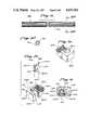
- FIG. 13is a side view in perspective of the master clamp assembly used to form the proper contour of the support rods in accordance with the present invention.
- FIG. 14is another view in perspective of the master clamp assembly illustrated in FIG. 13;
- FIG. 15is a diagrammatic view of another form of screw clamp assembly in accordance with this invention, two forms being illustrated;
- FIG. 16is a view, partly in section and partly in elevation, taken along the line 16--16 of FIG. 15 and illustrating the details of one modified form of screw clamp in accordance with this invention
- FIG. 17is a view, partly in section and partly in elevation, taken along the line 17--17 of FIG. 16;
- FIG. 18is a view, in elevation, as seen along the line 18--18 of FIG. 17;
- FIG. 19is a sectional view taken along the line 19--19 of FIG. 18;
- FIG. 20is a developed view of the lower saddle assembly of the modified form of screw clamp assembly previously illustrated;
- FIG. 21is a view in perspective of a serrated rod for use with the modified screw clamp assembly of the present invention.
- FIG. 21ais a sectional view taken along the line 21a-21a of FIG. 21;
- FIG. 22is a view, partly in section and partly in elevation, taken along the line 22--22 of FIG. 15 and illustrating the details of one modified form of screw clamp in accordance with this invention
- FIG. 23is a view, parly in section and partly in elevation, as taken alon the line 23--23 of FIG. 22;
- FIG. 24is a view in elevation as seen along the line 24--24 of FIG. 23;
- FIG. 25is a sectional view taken along the line 25--25 of FIG. 24.
- FIGS. 1 and 2illustrate somewhat diagrammatically the spinal support system 10 of the present invention installed in the spinal column generally designated 12.
- the spinal support system 10includes a plurality of screw clamp assemblies 15 each of which is preferably located between the spinous process 16 and the associated transverse process 17 on each side of the spinous process and in the posterior portion of the spinal column.
- This relative position of the screw clamp assembliesis preferred since the threaded end 20 of the screw clamp is located through the pedicle, a bony portion of the vertebra which will hold the clamps in place.
- the support system of this inventionis especially adapted to be used in the L1-L5 and S1-S2 region of the spine, although its use is not limited thereto.
- FIG. 1also illustrates the contour and curvature which may be achieved with the present invention.
- the spinal support system 10provides a markedly rigid support system which tends to inhibit left to right, front to back and rotational movements of the supported portion of the spinal column.
- the rigidity of the systemis due in part to the fact that the rods 21 and 22 cooperate with the clamps 15 to form a parallelogram on each side of the spinal column, a rigidity which is enhanced since there is purchase on each of the rods at spaced portions along the length of the rods, a gripping type of action which has significant advantages and which will be explained in detail later.
- the screw clamp assembliesinclude a threaded end 20 for placement into the bony structure of the vertebra of the spine, as may be determined by the surgeon.
- the preferred locationis through the pedicle, although other regions may be used, especially in the sacral region.
- the screw clamp assembliesmay be inserted directly or placed in a pre-drilled opening dimensioned to receive the threads so as to secure the screw firmly into an appropriate support structure of the spine.
- the configuration of the screw threadsis well known and is that normally used for screw members intended to be implanted in bone structures.
- the leading screw end of the clampterminates in a tapered flange 25, which faces the screw threads 20, as best seen in FIG. 6, the flange including a flat surface pocket portion 27 opposite the threaded end 20 for reception of a saddle assembly generally designated 30.
- the provision of a tapered flangepermits the saddle assembly to be positioned close to the vertebra into which the screw is positioned.
- the saddle assembly 30, in accordance with a preferred form of the invention,is removable from the screw and is preferably formed of a lower half 35 and an upper half 40 as seen in FIGS. 4, 5 and 6.
- Overall the outer surface of the saddle assemblyincludes flat front and rear surfaces 42 and 44 and curved or rounded end faces 46 and 48, as seen in FIG. 4, a geometry which facilitates positioning of the screw clamp assemblies in tight regions of the spinal structure.
- the upper or top surface 52 of the upper half 40 of the saddle assembly 30is beveled at 55 to eliminate sharp peripheral side edges.
- the upper half 40 of the saddle assemblyPreferably integrally formed on the upper half 40 of the saddle assembly are two depending fingers 57 and 59, see FIGS. 4 and 5, one located on each face 42 and 44, and dimensioned axially to extend somewhat below the upper surface 65 of the lower half 35 of the saddle assembly.
- the lower end of each of the fingersterminates in a reverse taper 57a and 59a which assists in camming the upper half over the lower half during the assembly of the two halves, as will be described.
- the length of the fingersis preferably such that the inner surfaces 57b and 59b of each of the fingers is opposite upper portion of the faces 70 and 71 of the lower half 35 of the saddle assembly, as seen in FIGS. 5 and 6.
- the upper half 40 of the saddle assemblyincludes an opening 75, as seen in FIG.
- the end 80 of the screw clampincludes a second threaded end 81, spaced from the flange 25 and whose thread configuration may be that of a machined screw.
- Received on the threaded end 81is a saddle locking assembly in the form of a securing nut 85 and a locking nut 86, as seen in FIGS. 5 and 6, and used to secure the two halves of the saddle assembly together.
- the lower half saddle 35includes a lower surface 100 which is tapered upwardly, as shown, and which follows the contour of the face of the flange 25.
- the faces 70 and 71 of the lower saddle halfare dimensioned such that the upper and lower halves have the same face to face dimensions.
- the lower halflike the upper half, includes rounded side faces 105 and 108 which follow the shape of side faces 46 and 48 of the upper half.
- the upper and lower halves of the saddle assemblyinclude a flat upper surface, a beveled and curved edge, a curved side face and a tapered lower face, as illustrated in FIG. 4. Overall, this provides an outer surface geometry which facilitates location of the screw clamp in regions of the spine in which the anatomy of the patient is such there is a minimal amount of room for the surgeon to work.
- the lower half of the saddle assemblyis intended to be installed by placing the upper half over the threaded end 80 of the screw clamp
- the lower halfis designed to be assembled by insertion laterally of the shaft of the screw clamp, followed by assembly of the upper half and appropriate locking of the saddle assembly.
- the lower half saddle 35is provided with a side opening 115 for sideways insertion on the shaft 120 of the screw clamp 15.
- this portion of the shaft, forming the lower half saddle receiving portion of the shaftis formed with a partial circular or semi-circular shape 122, parallel spaced side faces 124 and 126 and a flat front face 130.
- the lower half saddleincludes a complimentary shaped interior opening 140 having a partial circular shape 122a, parallel side faces 124a and 126a and an open front portion, as illustrated in FIG. 8.
- the side opening 115is formed with a vertically extending slot 150, which includes vertically extending walls 150a and 150b, each including an adjacent reverse tapered vertically extending wall segment 150c and 150d.
- a generally T-shaped lower half saddle lock member 170Receivable within the vertical slot 150 is a generally T-shaped lower half saddle lock member 170, the latter including tapered side faces 170a and 170b which form a dove-tail lock with the opposed wall segments 150c and 150d, as seen in the sectional view of FIG. 7.
- the cross-member 180 of the T-shaped lower saddle lock member 170is received in a counterbore 183 formed in the upper surface 52 of the lower half 35 of the saddle assembly.
- the shaft portion 120To locate the lower half 35 of the saddle properly on the shaft portion 120 of the screw clamp, the shaft portion 120 includes a shoulder 190, as shown in FIG. 5. It is understood that the lock member and the configuration of the receiving lower half saddle may be of the configuration hereinafter described.
- the shoulder 190is generally circular and includes a flat face 195, see FIG. 10, which forms a continuation of the face 130.
- the dimension from the upper surface of the flange 25 to the underside of the shoulder 190is approximately that of the axial dimension from the lower center surface of the lower half saddle 35 to the upper inside surface of the counterbore 183.
- the lower center surface 196 of the lower half of the saddleis flat in order to seat on the flat upper surface of the of the flange, as seen in FIG. 6, for example.
- a small non-threaded section 197 of the shaftis located between the threaded end 81 and the top of the shoulder 190.
- Proper assembly of the lower half saddle 35 to the screwinvolves alignment of the opening 115 axially with respect to the shoulder 190 and sliding the lower saddle in place on the shaft such that the counterbore is positioned to receive the shoulder.
- the curved surface 122a of the lower saddleshould be facing the curved section 122 of the shaft such that the curved and parallel side faces are in engagement.
- the saddle lock member 170is inserted in the keyway slot 150.
- the latteris provided with an aperture 200, as seen in FIGS. 6 and 9, and to which an appropriate tool may affixed for manipulation of the lock member.
- the face 203 of the saddle lock 170 which faces the the shaft 120is axially grooved, as indicated in FIG. 7, to fit over the threaded portion 81 of the screw clamp.
- the shoulder 190 and the flange 25operate to prevent axial movement of the lower half saddle while the lower saddle lock prevents lateral movement off the shaft.
- the upper saddle halfmay then be assembled over the shaft end 80 such that the finger facing the lower saddle lock overhangs the T-section 180 of the lower saddle lock to prevent movement of the saddle lock vertically out of the keyway.
- the latteris constructed in a symmetrical fashion such that either face may be positioned over the saddle lock, as seen in FIGS. 4 and 5.
- the saddle lock assemblyis designed to effect a firm gripping purchase on the rods 21 and 22 along a portion of the length thereof.
- each of the upper and lower halves of the saddle assemblyare provided with mating grooves 215a and 215b and 220a and 220b, the pairs of grooves being located on each side of the shaft.
- the groovesare dimensioned to be slightly smaller in dimension than the circumferential dimension of the rods.
- the diameter of the apertures in the saddle assemblymay be 0.154 of an inch while the rod diameter may be 0.155 of an inch.
- the rod diameter and the diameter of the aperturesare coordinated to provide an interference fit of 0.0010 of an inch between the rod and the associated groove when the screw clamp assembly is tightened on the rods. In part, it is this interference fit which provides good purchase between the clamp assembly and the associated rods and thus provides excellent internal fixation. It is also to be noted that the grooves are located to clear the shaft thereby permitting the shaft to be removed through the spaced rods. The rods and the faces of the grooves may be serrated, as will be described in order to provide increased enhanced purchase.
- the face-to-face dimensionmay be 0.375 of an inch, for example, with the center line of the grooves being spaced 0.460 of an inch, i.e., 0.230 of an inch on each side of the center line.
- the upper saddle halfmay be removed, the lower saddle lock 170 may be removed by lifting it vertically through the spaced rods 21 and 22 and the lower saddle half is slipped laterally out from under the rods, as indicated by the arrow in FIG. 10. Reassembly of the in-place screw clamp is just the reverse.
- the screw clamp 15may be installed in a component of the spinal structure with or without the saddle assembly attached. If the saddle assemby is not attached a tool may be used to grip the flat faces 122, 126 and 130 of the shaft to form a driving connection to the screw member. Alternatively, a tool may be used on the threaded end 81, with or without the saddle assembly present.
- a soft rodas for example, soft aluminum alloy, preferably of the same dimensions of the final installed rods, is assembled to the installed and the in-place screw clamp assemblies by starting at the center clamp of the set and working in each direction axially along the spine.
- the soft rodsare preferably cylindrical solid rods as indicated at 300 of FIG. 11.
- the length of the soft rods 300may vary depending upon the need. Since these rods are soft and easily manually formed, they are located in the grooves of the lower saddle assembly and locked in place with the upper half saddle and lock to form a replication or master of the relative position of the apertures of the saddle assemblies. It is preferred that the two rods for each set of screw clamp assemblies be formed at the same time so that a true relative replication may be made.
- relatively rigid rodssuch as 321 and 322 illustrated in FIG. 12, and to be described in detail, will be installed in the screw clamp assemblies.
- the rodsare marked, as by notches 321a, 321b and 322a.
- the rods 300form a temporary master to be used to configure the rods 321 and 322 to replicate the position of the screw clamp saddle assembly apertures.
- a plurality of rod master clamp assemblies 400as shown in FIGS. 13 and 14 are used.
- the rod master assembliesare mounted on a suitable support, not shown, such that there are a sufficient number of such units to match the number of installed screw clamps and in the same general alignment.
- Each master clamp assemblyincludes a foot 402 apertured to receive a bolt to lock the master clamp to a support, as illustrated.
- the footincludes a vertical support 405 which receives a head mounting shaft 410.
- the shaft 410may be positioned axially and rotationally in the support to achieve the desired orientation and height and locked into place by the bolts 415. This is done with each of the master clamps.
- a double articulating head assembly 420Carried by the shaft 410 is a double articulating head assembly 420 which includes a master clamp head 425 pivotable in two directions, as indicated in the dotted lines of FIG. 13, and which may be locked in place by bolt 426.
- the master clamp headincludes a master clamp 430 which essentially replicates the saddle assembly of the screw clamp insofar as the position of the apertures 430a and 430b are concerned.
- the master clampincludes an upper removable saddle 435 which may be secured in place by the lock system composed of a knurled fitting 437 and lock nut 438.
- a lower saddled 440is also provided and is likewise dimensioned to match the dimensions of the lower saddle half of the screw clamp assembly.
- the master head clampis mounted on an intermediate articulating head 450, pivotable in two directions, as indicated in dotted lines in FIG. 14, and which may be locked in place by the nut 452.
- the intermediate head 450 and the master head clamp 425are each independently movable and adjustable.
- the soft metal rods which form the temporary mastersare used to position the master head clamps 425 of each of the assemblies such that apertures 430a and 430b follow the contour of the soft metal masters and thus the contour of the screw clamp saddle assembly.
- each assemblyis relatively easily adjusted, as above described, to replicate the soft master contour and thus the that of the screw clamps.
- the soft master rodsare removed, without changing the settings, and the rods 321 and 322 are shaped to follow the contour of the master clamps. This may be accomplished with a bending tool, again starting at the center master clamp of the series and progressing towards the ends.
- the rigid rodsare shaped, they are assembled to the screw clamp assemblies, which are then locked in place, as described, with the result being the rigid support system already described. To assure that the lock nut does not back off, the end threads may be slightly deformed.
- any adjustmentis needed, due to the structure of the screw clamps, it is relatively easy to disassemble one of the clamps from the rods by backing off the lock nut and the securing nut, removing the upper saddle half, removing the lower saddle lock and sliding the lower saddle off the shaft.
- the screw clamp shaftmay be reset as needed or any other adjustments may be made as needed, without having to undo any other clamp or attachment to the rods.
- itmay have been necessary to undo the entire support system, especially in the case of hook or wire type assemblies, in order to effect an adjustment.
- the form of screw clamp assembly illustrated in FIG. 15is for a single rod system and two different forms are illustrated, 500 with a lower saddle lock and 800 to be described. As illustrated, the single rod screw assemblies may be positioned such that the rod is outboard, as shown, or arranged inboard, or one inboard and one outboard.
- the screw clamp assembly 500is somewhat similar to that previously described and includes a threaded end 520 for placement, the configuration of the threads being well known and as already described.
- the leading screw end of the clampterminates in a tapered flange 525, which faces the screw threads 520, as best seen in FIG. 18, the flange including a flat surface pocket position 527 opposite the threaded end 520 for reception of a saddle assembly generally designated 530.
- the provision of a tapered flangepermits the saddle assembly to be positioned close to the vertebra into which the screw is positioned.
- the saddle assembly 530in accordance with a preferred form of the invention, is removable from the screw and is preferably formed of a lower half 535 and an upper half 540 as seen in FIGS. 15, 17 and 18.
- Overall the outer surface of the saddle assemblyincludes flat front and rear surfaces 542 and 544 and a generally flat end face 546 and a rounded end face 548, as seen in FIG. 16, a geometry which facilitates positioning of the screw clamp assemblies in tight regions of the spinal structure.
- the upper or top surface 552 of the upper half 540 of the saddle assembly 530is beveled at 555 to eliminate sharp peripheral side edges.
- each of the fingersPreferably integrally formed on the upper half 540 of the saddle assembly are front and back depending fingers 557 and 558 and a side depending finger 559, see FIGS. 15, 16 and 18, each dimensioned axially to extend somewhat below the upper surface 565 of the lower half 535 of the saddle assembly.
- the lower end of each of the fingersterminates in a reverse taper, as illustrated, which assists in camming the upper half over the lower half during the assembly of the two halves, as already described.
- the upper half 540 of the saddle assemblyincludes an opening 575, as seen in FIG. 17, so that the other end 580 of the screw clamp may pass therethrough.
- the end 580 of the screw clampincludes a second threaded end 581, spaced from the flange 525 and whose thread configuration may be that of a machined screw.
- Received on the threaded end 581is a saddle locking assembly in the form of a securing nut 585 and a locking nut 586, as seen in FIGS. 17 and 18, and used to secure the two halves of the saddle assembly together.
- the lower half saddle 535includes a lower surface 600 which is tapered upwardly, as shown, and which follows the contour of the face of the flange 525.
- the faces 570 and 571 of the lower saddle halfare dimensioned such that the upper and lower halves have the same face to face dimensions.
- the lower halflike the upper half, includes a flat side face 605 and a rounded side face 608 which follow the shape of the corresponding side faces of the upper half for the reasons already noted. Overall, this provides an outer surface geometry which facilitates location of the screw clamp in regions of the spine in which the anatomy of the patient is such there is a minimal amount of room for the surgeon to work.
- the lower half saddle 535is provided with a side opening 615 for sideways insertion on the shaft 620 of the screw clamp.
- this portion of the shaft, forming the lower half saddle receiving portion of the shaftis formed with a partial circular or semi-circular shape 622, parallel spaced side faces 624 and 626 and a flat front face 630.
- the lower half saddleincludes a complimentary shaped interior opening 640 having a partial circular shape 622a, parallel side faces 624a and 626a and an open front portion, as illustrated in FIG. 20.
- the side opening 615is formed with spaced vertically extending slots 650, each of which includes vertically extending generally parallel walls 650a and 650b.
- a lower half saddle lock member 670Receivable within the vertical slot 650 is a lower half saddle lock member 670, somewhat different in configuration from the lock member 170 previously described.
- the saddle lock member 670includes laterally extending shoulders 670a and 670b received in the slot 650 as seen in the sectional view of FIG. 19.
- the dimension from the top face 680 to the bottom face 680a of the lower saddle lock member 670is such that when positioned in place, the top face is even with a counterbore 683 formed in the upper surface 552 of the lower half 535 of the saddle assembly.
- the lower face 680arests on the uuper face of flange 527.
- the shaft portion 620includes a shoulder 690, as shown in FIG. 17.
- the shoulder 690is generally circular and the dimension from the upper surface of the flange 525 to the underside of the shoulder 690 is approximately that of the axial dimension from the lower center surface of the lower half saddle 535 to the upper inside surface of the counterbore 583.
- the lower center surface 696 of the lower half of the saddleis flat in order to seat on the flat upper surface of the of the flange, as seen in FIG. 18, for example.
- a small non-threaded section 697 of the shaftImmediately above the shoulder 690 is a small non-threaded section 697 of the shaft, the section 697 being located between the threaded end 581 and the top of the shoulder 690, as seen in FIG. 17.
- Proper assembly of the lower half saddle 535 to the screwinvolves alignment of the opening 615 axially with respect to the shoulder 690 and sliding the lower saddle in place on the shaft such that the counterbore is positioned to receive the shoulder.
- the curved surface 622a of the lower saddleshould be facing the curved section 622 of the shaft such that the curved and parallel side faces are in engagement.
- the saddle lock member 670is inserted in the keyway slot 650.
- the latteris provided with an aperture 700, as seen in FIGS. 18 and 20, and to which an appropriate tool may affixed for manipulation of the lock member.
- the inner face 703 of the saddle lock 670 which faces the the shaft 620is axially grooved, as indicated in FIG. 19, to fit over the threaded portion 581 of the screw clamp.
- the shoulder 690 and the flange 525operate to prevent axial movement of the lower half saddle while the lower saddle lock prevents lateral movement off the shaft.
- the upper saddle halfmay then be assembled over the shaft end 580 such that the finger facing the lower saddle lock overhangs the lower saddle lock to prevent movement of the saddle lock vertically out of the keyway.
- the saddle lock assemblyis designed to effect a firm gripping purchase on the rod, to be described, along a portion of the length thereof.
- each of the upper and lower halves of the saddle assemblyare provided with mating grooves 720a and 720b, the grooves being located on one side of the shaft.
- the groovesare formed with serrations along their length, as illustrated and seen better in FIG. 20.
- the number of serrationsmay be as desired, and 50 serrations around the inner mating surfaces may, for example, be used.
- the face-to-face dimensionmay be 0.375 of an inch, for example, with the center line of the grooves being spaced 0.460 of an inch, i.e., 0.230 of an inch on each side of the center line.
- the upper saddle halfmay be removed, the lower saddle lock 670 may be removed by lifting it vertically and the lower saddle half is slipped laterally out from under the rod, as already described. Reassembly of the in-place screw clamp is just the reverse.
- the screw clampmay be installed in a component of the spinal structure with or without the saddle assembly attached. If the saddle assembly is not attached a tool may be used to grip the flat faces 622, 626 and 630 of the shaft to form a driving connection to the screw member. Alternatively, a tool may be used on the threaded end 581, with or without the saddle assembly present.
- FIGS. 21 and 21aillustrate the serrated rod 795 which may be used with a single rod system.
- the serrations 796extend around the entire periphery and all the way lenthwise and correspond in number to those of the screw clamp.
- the rodmay be dimensioned such that there is a tight interference fit between the mating parts.
- the form of screw clamp assembly illustrated at 800is similar to screw clamp assembly 500 but differs in the structure of the lower saddle; in all other respects the two are the same, except as noted.
- the lower saddle 835is essentially the same as 535 except that there is no saddle lock assembly and the lower saddle 835 is assembled over the screw rather than being inserted sideways.
- the lower saddleincludes an aperture 840 which includes a flat 845 which mates with a flat formed on the described receiving portion of the screw member for the purpose of orientation.
- the upper saddle 850may be as described in connection with 540 and is in fact essentially identical and interchangeable with either lower saddles of the two single rod systems described. Again, the mating surfaces of the upper and lower saddles are serrated as indicated at 870 for the reasons described. The assembly, removal and adjusment of this form of screw assembly is apparent from the prior detailed description.
- the single rod systems describedare placed in the patient, as described, and the mastering technique already described is followed. In effect, the procedure and advantages of the dual rod system are applicable to the single rod system, as is apparent from the prior detailed discussion.
- the clamps and rodsmay vary in dimensions since greater support may be needed for an active athelete than for an older, sedentary person.
- a variety of screw clamp lengthsmay be provided for each of the forms described.
- the threaded end of the screwmay be between 30 to 65 mm, and the screw threads may have a major diameter of between 5.4 mm and 6.9 mm or more, with a minor diameter of between 3.6 mm and 5.0 mm, with 9 threads per inch.
- the dimension from the flange to the end of the machine threadis usually the same for each clamp thus allowing for interchangeability of the saddle assemblies described as interchangeable to accommodate rods of different dimension.
- Maintaining the flange-to-end dimensionalso has the advantage of allowing replacement of only the shaft part of the screw assembly if that is necessary, i.e., use of a shaft with a longer threaded end in place of one with a shorter threaded end.
- the rigid rodsfor the dual or single rod system, may be from 4 to 8 inches in length and may be from 0.155 to 0.167 of an inch in diameter, with appropriate dimensions of the apertures to provide an interference fit, as described. If more strength is needed, the diameter of the rods may be increased since an increase in diameter of 0.020 of an inch tends to increase the rod strength by 50%. To illustrate the strength of the present system, the use of four rods of 0.155 of an inch diameter is thirty percent stronger than the use of 3/16 of an inch Luque rods.
- rods of the same dimensionare used on each side of the spinal column and in each set of clamps. It is understood, however, that there may be instances in which it may be desirable to provide a stronger support system on one side of the spinal column in which case the rods on one side may be of a greater diameter. It may also be desirable to provide more local support close to the center axis of the spine, in which event one of the rods affixed to the clamps may be of a greater diameter than the other rod affixed to the same clamp, the clamps being appropriately proportioned for purchase and interference fit with respect to each of the rods.
- All implanted components of the support fixationare fabricated of AISI 316L stainless steel, a chromium-nickel-molybdenum alloy, and chemically polished and passivated to resist corrosion by the body fluids and tissue, rather than electropolishing the finished parts. Electropolishing may cause intergranular corrosion which tends to promote metal fatigue.
- Another advantage of the present systemis that the components are firmly purchased and thus provide stability of internal fixation in that there is no sliding or relative movement between the parts. Such sliding or relative movement between the components of an implanted system are objectionable since this may result in destruction of the passive layer and may lead to a repassivation process which leads to corrosion and metal fatigue.
Landscapes
- Health & Medical Sciences (AREA)
- Life Sciences & Earth Sciences (AREA)
- Orthopedic Medicine & Surgery (AREA)
- Surgery (AREA)
- Medical Informatics (AREA)
- General Health & Medical Sciences (AREA)
- Biomedical Technology (AREA)
- Heart & Thoracic Surgery (AREA)
- Nuclear Medicine, Radiotherapy & Molecular Imaging (AREA)
- Molecular Biology (AREA)
- Animal Behavior & Ethology (AREA)
- Engineering & Computer Science (AREA)
- Public Health (AREA)
- Veterinary Medicine (AREA)
- Neurology (AREA)
- Oral & Maxillofacial Surgery (AREA)
- Pathology (AREA)
- Surgical Instruments (AREA)
Abstract
Description
Claims (25)
Priority Applications (5)
| Application Number | Priority Date | Filing Date | Title |
|---|---|---|---|
| US06/873,611US4653481A (en) | 1985-07-24 | 1986-06-18 | Advanced spine fixation system and method |
| DE3624067ADE3624067C2 (en) | 1985-07-24 | 1986-07-16 | Screw clamp arrangement and spinal support fixation system with such a screw clamp arrangement |
| GB8617846AGB2178323B (en) | 1985-07-24 | 1986-07-22 | Advanced spine fixation system and method |
| CA000515806ACA1304267C (en) | 1985-07-24 | 1986-07-23 | Advanced spine fixation system and method |
| CH2962/86ACH672420A5 (en) | 1985-07-24 | 1986-07-23 |
Applications Claiming Priority (2)
| Application Number | Priority Date | Filing Date | Title |
|---|---|---|---|
| US75829485A | 1985-07-24 | 1985-07-24 | |
| US06/873,611US4653481A (en) | 1985-07-24 | 1986-06-18 | Advanced spine fixation system and method |
Related Parent Applications (1)
| Application Number | Title | Priority Date | Filing Date |
|---|---|---|---|
| US75829485AContinuation-In-Part | 1985-07-24 | 1985-07-24 |
Publications (1)
| Publication Number | Publication Date |
|---|---|
| US4653481Atrue US4653481A (en) | 1987-03-31 |
Family
ID=27116519
Family Applications (1)
| Application Number | Title | Priority Date | Filing Date |
|---|---|---|---|
| US06/873,611Expired - LifetimeUS4653481A (en) | 1985-07-24 | 1986-06-18 | Advanced spine fixation system and method |
Country Status (5)
| Country | Link |
|---|---|
| US (1) | US4653481A (en) |
| CA (1) | CA1304267C (en) |
| CH (1) | CH672420A5 (en) |
| DE (1) | DE3624067C2 (en) |
| GB (1) | GB2178323B (en) |
Cited By (307)
| Publication number | Priority date | Publication date | Assignee | Title |
|---|---|---|---|---|
| US4763644A (en)* | 1984-02-28 | 1988-08-16 | Webb Peter J | Spinal fixation |
| US4773402A (en)* | 1985-09-13 | 1988-09-27 | Isola Implants, Inc. | Dorsal transacral surgical implant |
| US4790297A (en)* | 1987-07-24 | 1988-12-13 | Biotechnology, Inc. | Spinal fixation method and system |
| US4836196A (en)* | 1988-01-11 | 1989-06-06 | Acromed Corporation | Surgically implantable spinal correction system |
| US4887595A (en)* | 1987-07-29 | 1989-12-19 | Acromed Corporation | Surgically implantable device for spinal columns |
| US4946458A (en)* | 1986-04-25 | 1990-08-07 | Harms Juergen | Pedicle screw |
| US4950269A (en)* | 1988-06-13 | 1990-08-21 | Acromed Corporation | Spinal column fixation device |
| US5000165A (en)* | 1989-05-15 | 1991-03-19 | Watanabe Robert S | Lumbar spine rod fixation system |
| US5015255A (en)* | 1989-05-10 | 1991-05-14 | Spine-Tech, Inc. | Spinal stabilization method |
| US5030220A (en)* | 1990-03-29 | 1991-07-09 | Advanced Spine Fixation Systems Incorporated | Spine fixation system |
| US5034011A (en)* | 1990-08-09 | 1991-07-23 | Advanced Spine Fixation Systems Incorporated | Segmental instrumentation of the posterior spine |
| WO1991016020A1 (en)* | 1990-04-26 | 1991-10-31 | Danninger Medical Technology, Inc. | Transpedicular screw system and method of use |
| USD333184S (en) | 1990-02-23 | 1993-02-09 | Engineering & Precision Machining, Inc. | Pin clamp for use with an orthopedic appliance |
| USD334620S (en) | 1990-02-23 | 1993-04-06 | Engineering & Precision Machining, Inc. | Pin clamp for use with an orthopedic appliance |
| US5209752A (en)* | 1991-12-04 | 1993-05-11 | Danek Medical, Inc. | Lateral offset connector for spinal implant system |
| US5242443A (en)* | 1991-08-15 | 1993-09-07 | Smith & Nephew Dyonics, Inc. | Percutaneous fixation of vertebrae |
| US5254118A (en)* | 1991-12-04 | 1993-10-19 | Srdjian Mirkovic | Three dimensional spine fixation system |
| EP0325682B1 (en)* | 1988-01-21 | 1993-11-18 | Acromed Corporation | Bone screw |
| US5281225A (en)* | 1989-06-07 | 1994-01-25 | Guglielmo Vicenzi | Intramedullary pin with self-locking end for metadiaphyseal fractures of long bones |
| US5330473A (en)* | 1993-03-04 | 1994-07-19 | Advanced Spine Fixation Systems, Inc. | Branch connector for spinal fixation systems |
| US5342361A (en)* | 1993-01-14 | 1994-08-30 | Yuan Hansen A | Dual tier spinal locking and retrieving system and instrumentation for administering such system percutaneously |
| US5344422A (en)* | 1989-10-30 | 1994-09-06 | Synthes (U.S.A.) | Pedicular screw clamp |
| US5344421A (en)* | 1993-07-16 | 1994-09-06 | Amei Technologies Inc. | Apparatus and method for adjusting a bone plate |
| US5346493A (en)* | 1991-10-04 | 1994-09-13 | Acromed Corporation | Top-entry rod retainer |
| US5352224A (en)* | 1990-11-29 | 1994-10-04 | Howmedica Gmbh | Correction implant for the human vertebral column |
| US5368593A (en)* | 1992-07-07 | 1994-11-29 | Stark; John G. | Devices and methods for attachment of spine fixation devices |
| WO1995005126A1 (en)* | 1993-08-19 | 1995-02-23 | Danek Medical, Inc. | Attachement plate for top-tightening clamp assembly |
| US5403315A (en)* | 1992-04-29 | 1995-04-04 | Danek Medical, Inc. | Positionable spinal fixation device |
| WO1995013756A1 (en)* | 1993-11-19 | 1995-05-26 | Cross Medical Products, Inc. | Spine rod anchors, spine rod connectors and nut alignment guide |
| US5437669A (en)* | 1993-08-12 | 1995-08-01 | Amei Technologies Inc. | Spinal fixation systems with bifurcated connectors |
| US5445639A (en)* | 1989-05-10 | 1995-08-29 | Spine-Tech, Inc. | Intervertebral reamer construction |
| US5466237A (en)* | 1993-11-19 | 1995-11-14 | Cross Medical Products, Inc. | Variable locking stabilizer anchor seat and screw |
| US5468241A (en)* | 1988-02-18 | 1995-11-21 | Howmedica Gmbh | Support device for the human vertebral column |
| US5480440A (en)* | 1991-08-15 | 1996-01-02 | Smith & Nephew Richards, Inc. | Open surgical technique for vertebral fixation with subcutaneous fixators positioned between the skin and the lumbar fascia of a patient |
| US5486176A (en)* | 1991-03-27 | 1996-01-23 | Smith & Nephew Richards, Inc. | Angled bone fixation apparatus |
| US5487744A (en)* | 1993-04-08 | 1996-01-30 | Advanced Spine Fixation Systems, Inc. | Closed connector for spinal fixation systems |
| US5489308A (en)* | 1989-07-06 | 1996-02-06 | Spine-Tech, Inc. | Spinal implant |
| US5496321A (en)* | 1993-11-19 | 1996-03-05 | Cross Medical Products, Inc. | Rod anchor seat having a sliding interlocking rod connector |
| US5498264A (en)* | 1992-07-21 | 1996-03-12 | Synthes (U.S.A.) | Clamp connection for connecting two construction components for a setting device, particularly an osteosynthetic setting device |
| WO1996014801A1 (en)* | 1994-11-16 | 1996-05-23 | Advanced Spine Fixation Systems, Incorporated | Segmental lamina grapple hooks |
| US5520687A (en)* | 1992-09-02 | 1996-05-28 | Advanced Spine Fixation Systems, Inc. | Low profile spine fixation system |
| US5545228A (en)* | 1991-08-15 | 1996-08-13 | Smith & Nephew Richards Inc. | Offset bone bolt |
| US5545165A (en)* | 1992-10-09 | 1996-08-13 | Biedermann Motech Gmbh | Anchoring member |
| US5571102A (en)* | 1992-09-15 | 1996-11-05 | Cavagna; Remi | System for spinal osteosynthesis |
| US5584887A (en)* | 1991-08-15 | 1996-12-17 | Smith & Nephew Richards, Inc. | Percutaneous screw adapter |
| US5613967A (en)* | 1995-04-28 | 1997-03-25 | Acromed Corporation | Apparatus for maintaining bone portions in a desired spatial relationship |
| US5620443A (en)* | 1995-01-25 | 1997-04-15 | Danek Medical, Inc. | Anterior screw-rod connector |
| US5653708A (en)* | 1992-12-28 | 1997-08-05 | Advanced Spine Fixation Systems, Inc. | Cervical spine rod fixation system |
| US5658286A (en)* | 1996-02-05 | 1997-08-19 | Sava; Garard A. | Fabrication of implantable bone fixation elements |
| US5669910A (en)* | 1996-01-02 | 1997-09-23 | Pioneer Laboratories, Inc. | Crosslink for implantable rods |
| US5749916A (en)* | 1997-01-21 | 1998-05-12 | Spinal Innovations | Fusion implant |
| USD394997S (en) | 1996-11-07 | 1998-06-09 | Diamond Communication Products, Inc. | Ganged cable clip |
| US5794897A (en)* | 1996-04-22 | 1998-08-18 | Andrew Corporation | Transmission line hanger, a method of attaching the hanger and the resulting assembly |
| US5885299A (en)* | 1994-09-15 | 1999-03-23 | Surgical Dynamics, Inc. | Apparatus and method for implant insertion |
| US5895427A (en)* | 1989-07-06 | 1999-04-20 | Sulzer Spine-Tech Inc. | Method for spinal fixation |
| EP0923908A1 (en) | 1997-12-17 | 1999-06-23 | Robert Lange | Apparatus for stabilizing certain vertebrae of the spine |
| WO2000015126A1 (en) | 1998-09-15 | 2000-03-23 | Advanced Spine Fixation Systems, Inc. | Transverse connector for spinal fixation systems |
| US6077262A (en)* | 1993-06-04 | 2000-06-20 | Synthes (U.S.A.) | Posterior spinal implant |
| US6086589A (en)* | 1999-02-02 | 2000-07-11 | Spineology, Inc. | Method and device for fixing spondylolisthesis posteriorly |
| US6099528A (en)* | 1997-05-29 | 2000-08-08 | Sofamor S.N.C. | Vertebral rod for spinal osteosynthesis instrumentation and osteosynthesis instrumentation, including said rod |
| US6183478B1 (en) | 1999-02-04 | 2001-02-06 | Depuy Orthopaedics, Inc. | Temporary fixation device |
| US6197028B1 (en)* | 1990-10-05 | 2001-03-06 | Sdgi Holdings, Inc. | Sacral implant system |
| US6206879B1 (en) | 1998-10-22 | 2001-03-27 | Aesculap Ag & Co. Kg | Osteosynthetic holding system |
| EP1101448A2 (en) | 1999-11-17 | 2001-05-23 | The University of Hong Kong | Anterior transpedicular fixation system and method for maintaining a vertebral column |
| US6248104B1 (en) | 1997-04-01 | 2001-06-19 | Daniel Chopin | Apparatus for osteosynthesis comprising a connector of the spinal pin and the anchoring elements |
| EP0699055B2 (en)† | 1993-05-18 | 2001-09-19 | Schäfer micomed GmbH | Osteosynthesis device |
| WO2002009606A2 (en) | 2000-08-02 | 2002-02-07 | Sulzer Spine-Tech Inc. | Posterior oblique lumbar arthrodesis |
| US6432108B1 (en) | 2000-01-24 | 2002-08-13 | Depuy Orthopaedics, Inc. | Transverse connector |
| US20020111627A1 (en)* | 2001-01-23 | 2002-08-15 | Philippe Vincent-Prestigiacomo | Position-adjustment system for an instrument for surgery of the spine |
| US6458131B1 (en) | 2000-08-07 | 2002-10-01 | Salut, Ltd. | Apparatus and method for reducing spinal deformity |
| US6478798B1 (en) | 2001-05-17 | 2002-11-12 | Robert S. Howland | Spinal fixation apparatus and methods for use |
| US20030004572A1 (en)* | 2001-03-02 | 2003-01-02 | Goble E. Marlowe | Method and apparatus for spine joint replacement |
| US6520990B1 (en)* | 1990-10-05 | 2003-02-18 | Sdgi Holdings, Inc. | Lateral fixation plates for a spinal system |
| US20030060823A1 (en)* | 2001-09-24 | 2003-03-27 | Bryan Donald W. | Pedicle screw spinal fixation device |
| WO2003047442A1 (en) | 2001-12-07 | 2003-06-12 | Mathys Medizinaltechnik Ag | Damping element and device for stabilisation of adjacent vertebral bodies |
| US20030114854A1 (en)* | 1994-09-15 | 2003-06-19 | Howmedica Osteonics Corp. | Conically shaped anterior fusion cage and method of implantation |
| US20030114853A1 (en)* | 2001-10-12 | 2003-06-19 | Ian Burgess | Polyaxial cross connector |
| US6610063B2 (en) | 2000-07-28 | 2003-08-26 | Synthes (Usa) | Spinal fixation system |
| US20030191532A1 (en)* | 2000-11-29 | 2003-10-09 | Goble E. Marlowe | Facet joint replacement |
| US6635086B2 (en) | 2000-05-30 | 2003-10-21 | Blacksheep Technologies Incorporated | Implant for placement between cervical vertebrae |
| US20040039385A1 (en)* | 2000-12-07 | 2004-02-26 | Keyvan Mazda | Device for fixing a rod and a spherical symmetry screw head |
| US20040049188A1 (en)* | 2002-09-09 | 2004-03-11 | Depuy Acromed, Inc. | Snap-on spinal rod connector |
| US20040061030A1 (en)* | 2002-10-01 | 2004-04-01 | Andrew Corporation | Cable hanger |
| US6733502B2 (en) | 2002-05-15 | 2004-05-11 | Cross Medical Products, Inc. | Variable locking spinal screw having a knurled collar |
| US20040092934A1 (en)* | 2002-04-24 | 2004-05-13 | Howland Robert S. | Multi selective axis spinal fixation system |
| US6736817B2 (en) | 1999-12-17 | 2004-05-18 | Thomas N. Troxell | Transconnector for coupling spinal rods |
| US6743231B1 (en) | 2000-10-02 | 2004-06-01 | Sulzer Spine-Tech Inc. | Temporary spinal fixation apparatuses and methods |
| US6752807B2 (en) | 1997-05-15 | 2004-06-22 | Howmedica Osteonics Corp. | Transverse rod connector clip |
| US6770075B2 (en) | 2001-05-17 | 2004-08-03 | Robert S. Howland | Spinal fixation apparatus with enhanced axial support and methods for use |
| US20040172020A1 (en)* | 2001-04-06 | 2004-09-02 | Jacques Beaurain | Spinal osteosynthesis device and preparation method |
| US20040215343A1 (en)* | 2000-02-28 | 2004-10-28 | Stephen Hochschuler | Method and apparatus for treating a vertebral body |
| US20040215191A1 (en)* | 2003-04-25 | 2004-10-28 | Kitchen Michael S. | Spinal curvature correction device |
| US20040215190A1 (en)* | 2003-04-25 | 2004-10-28 | Nguyen Thanh V. | System and method for minimally invasive posterior fixation |
| US20040243128A1 (en)* | 2001-05-17 | 2004-12-02 | Howland Robert S. | Selective axis posterior lumbar spinal plating fixation apparatus and methods for use |
| US20040254577A1 (en)* | 2001-10-18 | 2004-12-16 | Joel Delecrin | Progressive approach osteosynthesis device and preassembly method |
| US20040260284A1 (en)* | 2003-06-23 | 2004-12-23 | Matthew Parker | Anti-splay pedicle screw |
| US20050010215A1 (en)* | 2001-10-18 | 2005-01-13 | Joel Delecrin | Plate for osteosynthesis device and preassembling method |
| US20050080486A1 (en)* | 2000-11-29 | 2005-04-14 | Fallin T. Wade | Facet joint replacement |
| US6893443B2 (en) | 1999-07-07 | 2005-05-17 | Synthes (U.S.A) | Angle-adjustable bone screw and fixation device |
| US20050107788A1 (en)* | 2001-12-12 | 2005-05-19 | Jacques Beaurain | Implant for osseous anchoring with polyaxial head |
| US20050131537A1 (en)* | 2003-12-10 | 2005-06-16 | Hoy Robert W. | Spinal facet joint implant |
| US20050228326A1 (en)* | 2004-03-31 | 2005-10-13 | Depuy Spine, Inc. | Head-to-head connector spinal fixation system |
| US20050228377A1 (en)* | 2004-04-07 | 2005-10-13 | Depuy Spine, Inc. | Spinal cross-connectors |
| US20050277920A1 (en)* | 2004-05-28 | 2005-12-15 | Slivka Michael A | Non-fusion spinal correction systems and methods |
| US20060036252A1 (en)* | 2004-08-12 | 2006-02-16 | Baynham Bret O | Polyaxial screw |
| US20060038946A1 (en)* | 2003-03-31 | 2006-02-23 | Sharp Kabushiki Kaisha | Liquid crystal display device and method of manufacturing the same |
| US20060058789A1 (en)* | 2004-08-27 | 2006-03-16 | Depuy Spine, Inc. | Dual rod cross connectors and inserter tools |
| US20060064091A1 (en)* | 2004-03-31 | 2006-03-23 | Depuy Spine, Inc. | Rod attachment for head to head cross connector |
| US20060064092A1 (en)* | 2001-05-17 | 2006-03-23 | Howland Robert S | Selective axis serrated rod low profile spinal fixation system |
| US20060069390A1 (en)* | 2003-04-15 | 2006-03-30 | Robert Frigg | Bone fixation device |
| WO2006039765A1 (en)* | 2004-10-13 | 2006-04-20 | Stanislav Georgiev Nestorov | System for stabilization of spinal column |
| US20060149379A1 (en)* | 2000-07-21 | 2006-07-06 | Spineology, Inc. | Expandable porous mesh bag device and methods of use for reduction, filling, fixation and supporting of bone |
| US20060161154A1 (en)* | 2004-12-10 | 2006-07-20 | Mcafee Paul | Prosthetic spinous process and method |
| US20060195096A1 (en)* | 2005-02-09 | 2006-08-31 | David Lee | Bone fixation apparatus |
| US20060200149A1 (en)* | 2005-02-22 | 2006-09-07 | Hoy Robert W | Polyaxial orhtopedic fastening apparatus |
| US20060217718A1 (en)* | 2005-03-28 | 2006-09-28 | Facet Solutions, Inc. | Facet joint implant crosslinking apparatus and method |
| US20060241596A1 (en)* | 2005-04-26 | 2006-10-26 | Alan Rezach | Open dorsal adjusting connector |
| US20060264934A1 (en)* | 2005-05-18 | 2006-11-23 | Medicinelodge, Inc. | System and method for orthopedic implant configuration |
| US7141051B2 (en) | 2003-02-05 | 2006-11-28 | Pioneer Laboratories, Inc. | Low profile spinal fixation system |
| US20060271045A1 (en)* | 2005-05-27 | 2006-11-30 | Depuy Spine, Inc. | Spinal cross-connector |
| US20060271048A1 (en)* | 2005-05-12 | 2006-11-30 | Jeffery Thramann | Pedicle screw based vertebral body stabilization apparatus |
| US20070016296A1 (en)* | 2004-06-02 | 2007-01-18 | Triplett Daniel J | Surgical measurement systems and methods |
| US20070043357A1 (en)* | 2005-07-29 | 2007-02-22 | X-Spine Systems, Inc. | Capless multiaxial screw and spinal fixation assembly and method |
| US20070055242A1 (en)* | 2005-07-27 | 2007-03-08 | Bailly Frank E | Device for securing spinal rods |
| US20070073289A1 (en)* | 2005-09-27 | 2007-03-29 | Depuy Spine, Inc. | Posterior dynamic stabilization systems and methods |
| US20070123860A1 (en)* | 2005-11-04 | 2007-05-31 | Sdgi Holdings, Inc. | Dorsal adjusting multi-rod connector |
| US20070161997A1 (en)* | 2005-05-12 | 2007-07-12 | Lanx, Llc | Dynamic spinal stabilization |
| US20070191841A1 (en)* | 2006-01-27 | 2007-08-16 | Sdgi Holdings, Inc. | Spinal rods having different flexural rigidities about different axes and methods of use |
| US20070213719A1 (en)* | 2006-03-07 | 2007-09-13 | Zimmer Spine, Inc. | Spinal stabilization device |
| US20070233079A1 (en)* | 2006-02-06 | 2007-10-04 | Stryker Spine | Rod contouring apparatus and method for percutaneous pedicle screw extension |
| US7285121B2 (en) | 2001-11-05 | 2007-10-23 | Warsaw Orthopedic, Inc. | Devices and methods for the correction and treatment of spinal deformities |
| US20070270816A1 (en)* | 2006-04-24 | 2007-11-22 | Sdgi Holdings, Inc. | Connector apparatus |
| US20070270818A1 (en)* | 2006-04-24 | 2007-11-22 | Sdgi Holdings, Inc. | Connector apparatus |
| US20070270843A1 (en)* | 2006-05-16 | 2007-11-22 | Wilfried Matthis | Longitudinal member for use in spinal or trauma surgery and stabilization device with such a longitudinal member |
| US20070270817A1 (en)* | 2006-04-24 | 2007-11-22 | Sdgi Holdings, Inc. | Connector apparatus |
| US20080058808A1 (en)* | 2006-06-14 | 2008-03-06 | Spartek Medical, Inc. | Implant system and method to treat degenerative disorders of the spine |
| US7344537B1 (en)* | 2004-03-05 | 2008-03-18 | Theken Spine, Llc | Bone fixation rod system |
| US20080071277A1 (en)* | 2004-10-25 | 2008-03-20 | Warnick David R | Pedicle Screw Systems and Methods of Assembling/Installing the Same |
| US20080097447A1 (en)* | 2006-09-18 | 2008-04-24 | Warsaw Orthopedic, Inc. | Orthopedic plate system |
| US20080167688A1 (en)* | 2005-02-22 | 2008-07-10 | Facet Solutions, Inc. | Taper-Locking Fixation System |
| US20080167655A1 (en)* | 2007-01-05 | 2008-07-10 | Jeffrey Chun Wang | Interspinous implant, tools and methods of implanting |
| US20080208256A1 (en)* | 2006-11-10 | 2008-08-28 | Lanx, Llc | Pedicle based spinal stabilization with adjacent vertebral body support |
| US20080221622A1 (en)* | 2007-01-10 | 2008-09-11 | Facet Solutions, Inc. | Facet Joint Replacement |
| US20080234766A1 (en)* | 2007-01-29 | 2008-09-25 | Polaris Biotechnology, Inc. | Craniospinal fusion method and apparatus |
| US20080306528A1 (en)* | 2007-06-05 | 2008-12-11 | Spartek Medical, Inc. | Deflection rod system for spine implant with end connectors and method |
| US20080306556A1 (en)* | 2007-06-05 | 2008-12-11 | Spartek Medical, Inc. | Bone anchor with a curved mounting element for a dynamic stabilization and motion preservation spinal implantation system and method |
| US20080312655A1 (en)* | 2007-06-14 | 2008-12-18 | X-Spine Systems, Inc. | Polyaxial screw system and method having a hinged receiver |
| US20090012565A1 (en)* | 2007-06-06 | 2009-01-08 | Vertech, Inc. | Medical device and method to correct deformity |
| US20090018584A1 (en)* | 2007-01-29 | 2009-01-15 | Polaris Biotechnology, Inc. | Vertebra attachment method and system |
| US20090024166A1 (en)* | 2004-08-03 | 2009-01-22 | Vertech Innovations, Llc. | Facet device and method |
| US20090024169A1 (en)* | 2004-06-02 | 2009-01-22 | Facet Solutions, Inc. | System and method for multiple level facet joint arthroplasty and fusion |
| US20090036894A1 (en)* | 2007-01-29 | 2009-02-05 | Polaris Biotechnology, Inc. | Method of treating a neurological condition through correction and stabilization of the clivo-axial angle |
| US20090043338A1 (en)* | 2007-02-14 | 2009-02-12 | Showa Ika Kohgyo Co., Ltd. | Vertebra connection member and nut driver |
| US20090062859A1 (en)* | 2007-08-31 | 2009-03-05 | Michael Mahoney | Method and system for securing a rod to a bone anchor with a connector |
| US20090062857A1 (en)* | 2007-08-31 | 2009-03-05 | Ramsay Christopher L | Minimally invasive guide system |
| US20090062918A1 (en)* | 2007-08-30 | 2009-03-05 | Jeffrey Chun Wang | Interspinous implant, tools and methods of implanting |
| US20090062822A1 (en)* | 2007-08-31 | 2009-03-05 | Frasier William J | Adaptable clamping mechanism for coupling a spinal fixation element to a bone anchor |
| US20090062864A1 (en)* | 2007-08-31 | 2009-03-05 | Steven Ludwig | Offset connection bone anchor assembly |
| US20090062858A1 (en)* | 2007-08-31 | 2009-03-05 | Sara Dziedzic | Methods and instruments for approximating misaligned |
| US20090105832A1 (en)* | 2007-06-08 | 2009-04-23 | Ldr Medical | Intersomatic cage, intervertebral prosthesis, anchoring device and implantation instruments |
| US20090105763A1 (en)* | 2007-10-17 | 2009-04-23 | X-Spine Systems, Inc. | Cross connector apparatus for spinal fixation rods |
| US20090125065A1 (en)* | 2007-02-14 | 2009-05-14 | Showa Ika Kohgyo Co., Ltd. | Vertebra connection member and nut driver |
| US7533933B2 (en) | 2004-08-12 | 2009-05-19 | Cybex Industrial, Ltd. | Child seat for a motor vehicle |
| US20090163961A1 (en)* | 2007-12-19 | 2009-06-25 | X-Spine Systems, Inc. | Offset multiaxial or polyaxial screw, system and assembly |
| US20090177230A1 (en)* | 2008-01-08 | 2009-07-09 | Polaris Biotechnology, Inc. | Osteointegration apparatus |
| US7566345B1 (en) | 2001-03-01 | 2009-07-28 | Facet Solutions, Inc | Prosthesis for the replacement of a posterior element of a vertebra |
| US20090240280A1 (en)* | 2008-03-19 | 2009-09-24 | Jeffrey Chun Wang | Interspinous implant, tools and methods of implanting |
| US7604655B2 (en) | 2004-10-25 | 2009-10-20 | X-Spine Systems, Inc. | Bone fixation system and method for using the same |
| US20090281571A1 (en)* | 2008-05-08 | 2009-11-12 | Aesculap Implant Systems, Inc. | Minimally invasive spinal stabilization system |
| US20100030267A1 (en)* | 2007-06-05 | 2010-02-04 | Spartek Medical, Inc. | Surgical tool and method for implantation of a dynamic bone anchor |
| US20100030271A1 (en)* | 2008-02-26 | 2010-02-04 | Spartek Medical, Inc. | Modular in-line deflection rod and bone anchor system and method for dynamic stabilization of the spine |
| US20100030279A1 (en)* | 2008-02-26 | 2010-02-04 | Spartek Medical, Inc. | Load-sharing bone anchor having a deflectable post and axial spring and method for dynamic stabilization of the spine |
| US20100030274A1 (en)* | 2007-06-05 | 2010-02-04 | Spartek Medical, Inc. | Dynamic spinal rod and method for dynamic stabilization of the spine |
| US20100030270A1 (en)* | 2007-06-05 | 2010-02-04 | Spartek Medical, Inc. | Dynamic spinal rod assembly and method for dynamic stabilization of the spine |
| US20100030224A1 (en)* | 2008-02-26 | 2010-02-04 | Spartek Medical, Inc. | Surgical tool and method for connecting a dynamic bone anchor and dynamic vertical rod |
| US20100030273A1 (en)* | 2008-02-26 | 2010-02-04 | Spartek Medical, Inc. | Versatile polyaxial connector assembly and method for dynamic stabilization of the spine |
| US20100036436A1 (en)* | 2008-02-26 | 2010-02-11 | Spartek Medical, Inc. | Load-sharing bone anchor having a durable compliant member and method for dynamic stabilization of the spine |
| US20100036437A1 (en)* | 2008-02-26 | 2010-02-11 | Spartek Medical, Inc. | Load-sharing bone anchor having a deflectable post with a compliant ring and method for stabilization of the spine |
| US20100036435A1 (en)* | 2008-02-26 | 2010-02-11 | Spartek Medical, Inc. | Load-sharing bone anchor having a deflectable post and method for dynamic stabilization of the spine |
| US7686835B2 (en) | 2005-10-04 | 2010-03-30 | X-Spine Systems, Inc. | Pedicle screw system with provisional locking aspects |
| US20100087873A1 (en)* | 2008-10-06 | 2010-04-08 | Warsaw Orthopedics, Inc. | Surgical Connectors for Attaching an Elongated Member to a Bone |
| US20100114103A1 (en)* | 2008-11-06 | 2010-05-06 | The Regents Of The University Of California | Apparatus and methods for alteration of anatomical features |
| US7722647B1 (en) | 2005-03-14 | 2010-05-25 | Facet Solutions, Inc. | Apparatus and method for posterior vertebral stabilization |
| US20100152575A1 (en)* | 2008-01-08 | 2010-06-17 | Polaris Biotechnology, Inc. | Mathematical Relationship of Strain, Neurological Dysfunction and Abnormal Behavior Resulting from Neurological Dysfunction of the Brainstem |
| US20100152855A1 (en)* | 2000-07-21 | 2010-06-17 | Kuslich Stephen D | Expandable porous mesh bag device and methods of use for reduction, filling, fixation and supporting of bone |
| US20100168795A1 (en)* | 2008-02-26 | 2010-07-01 | Spartek Medical, Inc. | Load-sharing bone anchor having a natural center of rotation and method for dynamic stabilization of the spine |
| WO2010080337A1 (en) | 2008-12-18 | 2010-07-15 | Disc Dynamics, Inc. | Inflatable mold for maintaining posterior spinal elements in a desired alignment |
| US20100179597A1 (en)* | 2007-01-29 | 2010-07-15 | Polaris Biotechnology, Inc. | Craniospinal fusion method and apparatus |
| US20100198264A1 (en)* | 1992-03-02 | 2010-08-05 | Stryker Trauma Gmbh | Apparatus for bracing vertebrae |
| US20100211100A1 (en)* | 2009-02-19 | 2010-08-19 | Mack Claudia | Apparatus for spinal-column stabilization |
| US20100249836A1 (en)* | 2009-03-26 | 2010-09-30 | Kspine, Inc. | Alignment system with longitudinal support features |
| JP2010234078A (en)* | 2002-08-28 | 2010-10-21 | Smith & Nephew Inc | System, method and device for fastening and refastening orthopedic cable |
| CN101884562A (en)* | 2009-05-15 | 2010-11-17 | 史赛克创伤公司 | Securing clip |
| US20100318129A1 (en)* | 2009-06-16 | 2010-12-16 | Kspine, Inc. | Deformity alignment system with reactive force balancing |
| US20110015677A1 (en)* | 2004-03-03 | 2011-01-20 | Biedermann Motech Gmbh | Anchoring element and stabilization device for the dynamic stabilization of vertebrae or bones using such anchoring elements |
| US20110054536A1 (en)* | 2008-11-11 | 2011-03-03 | Kspine, Inc. | Growth directed vertebral fixation system with distractible connector(s) and apical control |
| US20110066188A1 (en)* | 2009-09-15 | 2011-03-17 | Kspine, Inc. | Growth modulation system |
| US20110098706A1 (en)* | 2007-09-27 | 2011-04-28 | Mullaney Michael W | Method and clamping apparatus for external fixation and stabilization |
| WO2011057178A1 (en) | 2009-11-06 | 2011-05-12 | Dean Lin | System and method for stabilizing and fixating lumbar vertebrae |
| US20110118783A1 (en)* | 2009-11-16 | 2011-05-19 | Spartek Medical, Inc. | Load-sharing bone anchor having a flexible post and method for dynamic stabilization of the spine |
| US7963978B2 (en) | 2007-06-05 | 2011-06-21 | Spartek Medical, Inc. | Method for implanting a deflection rod system and customizing the deflection rod system for a particular patient need for dynamic stabilization and motion preservation spinal implantation system |
| US20110172663A1 (en)* | 2006-02-22 | 2011-07-14 | Extraortho, Inc. | Articulation apparatus for external fixation device |
| US20110178559A1 (en)* | 2010-01-15 | 2011-07-21 | Ebi, Llc | Uniplanar bone anchor system |
| US20110178558A1 (en)* | 2010-01-15 | 2011-07-21 | Ebi, Llc | Uniplanar bone anchor system |
| US20110218579A1 (en)* | 2003-06-18 | 2011-09-08 | Jackson Roger P | Polyaxial bone anchor with helical capture connection, insert and dual locking assembly |
| US8021396B2 (en) | 2007-06-05 | 2011-09-20 | Spartek Medical, Inc. | Configurable dynamic spinal rod and method for dynamic stabilization of the spine |
| US8057515B2 (en) | 2008-02-26 | 2011-11-15 | Spartek Medical, Inc. | Load-sharing anchor having a deflectable post and centering spring and method for dynamic stabilization of the spine |
| US8057518B2 (en) | 2007-08-31 | 2011-11-15 | Depuy Spine, Inc. | Spanning connector for connecting a spinal fixation element and an offset bone anchor |
| US8097024B2 (en) | 2008-02-26 | 2012-01-17 | Spartek Medical, Inc. | Load-sharing bone anchor having a deflectable post and method for stabilization of the spine |
| US8097025B2 (en) | 2005-10-25 | 2012-01-17 | X-Spine Systems, Inc. | Pedicle screw system configured to receive a straight or curved rod |
| US20120035663A1 (en)* | 2003-04-09 | 2012-02-09 | Jackson Roger P | Dynamic stabilization medical implant assemblies and methods |
| US8114134B2 (en) | 2007-06-05 | 2012-02-14 | Spartek Medical, Inc. | Spinal prosthesis having a three bar linkage for motion preservation and dynamic stabilization of the spine |
| US8197517B1 (en) | 2007-05-08 | 2012-06-12 | Theken Spine, Llc | Frictional polyaxial screw assembly |
| US20120209332A1 (en)* | 2011-02-14 | 2012-08-16 | Pioneer Surgical Technology, Inc. | Spinal Fixation System And Method |
| US8257397B2 (en) | 2009-12-02 | 2012-09-04 | Spartek Medical, Inc. | Low profile spinal prosthesis incorporating a bone anchor having a deflectable post and a compound spinal rod |
| US20120271355A1 (en)* | 2011-04-25 | 2012-10-25 | Warsaw Orthopedic, Inc. | Elongated connecting elements for minimally invasive surgical procedures |
| US8337536B2 (en) | 2008-02-26 | 2012-12-25 | Spartek Medical, Inc. | Load-sharing bone anchor having a deflectable post with a compliant ring and method for stabilization of the spine |
| US8361117B2 (en) | 2006-11-08 | 2013-01-29 | Depuy Spine, Inc. | Spinal cross connectors |
| US8430916B1 (en) | 2012-02-07 | 2013-04-30 | Spartek Medical, Inc. | Spinal rod connectors, methods of use, and spinal prosthesis incorporating spinal rod connectors |
| US20130144342A1 (en)* | 2010-06-28 | 2013-06-06 | K2M, Inc. | Spine stabilization system |
| US8518085B2 (en) | 2010-06-10 | 2013-08-27 | Spartek Medical, Inc. | Adaptive spinal rod and methods for stabilization of the spine |
| US8728078B2 (en) | 2010-11-04 | 2014-05-20 | Zimmer, Inc. | Clamping assembly with links |
| US8734446B2 (en) | 2010-10-12 | 2014-05-27 | Zimmer, Inc. | External fixation surgical clamp with swivel |
| US8790375B2 (en) | 2011-03-18 | 2014-07-29 | Raed M. Ali, M.D., Inc. | Transpedicular access to intervertebral spaces and related spinal fusion systems and methods |
| US8840611B2 (en) | 2010-10-12 | 2014-09-23 | Zimmer, Inc. | Single lock external fixation clamp arrangement and method |
| US8845691B2 (en) | 2003-09-01 | 2014-09-30 | Ldr Medical | Osseous anchoring implant with a polyaxial head and method for installing the implant |
| US8852239B2 (en) | 2013-02-15 | 2014-10-07 | Roger P Jackson | Sagittal angle screw with integral shank and receiver |
| US8870928B2 (en) | 2002-09-06 | 2014-10-28 | Roger P. Jackson | Helical guide and advancement flange with radially loaded lip |
| US8911478B2 (en) | 2012-11-21 | 2014-12-16 | Roger P. Jackson | Splay control closure for open bone anchor |
| US8920472B2 (en) | 2011-11-16 | 2014-12-30 | Kspine, Inc. | Spinal correction and secondary stabilization |
| US8920473B2 (en) | 2006-12-10 | 2014-12-30 | Paradigm Spine, Llc | Posterior functionally dynamic stabilization system |
| US8926670B2 (en) | 2003-06-18 | 2015-01-06 | Roger P. Jackson | Polyaxial bone screw assembly |
| US8926672B2 (en) | 2004-11-10 | 2015-01-06 | Roger P. Jackson | Splay control closure for open bone anchor |
| US8992579B1 (en)* | 2011-03-08 | 2015-03-31 | Nuvasive, Inc. | Lateral fixation constructs and related methods |
| US8998960B2 (en) | 2004-11-10 | 2015-04-07 | Roger P. Jackson | Polyaxial bone screw with helically wound capture connection |
| US8998959B2 (en) | 2009-06-15 | 2015-04-07 | Roger P Jackson | Polyaxial bone anchors with pop-on shank, fully constrained friction fit retainer and lock and release insert |
| US9060815B1 (en) | 2012-03-08 | 2015-06-23 | Nuvasive, Inc. | Systems and methods for performing spine surgery |
| US9084634B1 (en) | 2010-07-09 | 2015-07-21 | Theken Spine, Llc | Uniplanar screw |
| US20150223844A1 (en)* | 2011-07-15 | 2015-08-13 | Globus Medical, Inc. | Orthopedic fixation devices and methods of installation thereof |
| US9138260B2 (en) | 2010-07-01 | 2015-09-22 | Zimmer, Inc. | Multi-locking external fixation clamp |
| US9149296B2 (en) | 2010-12-09 | 2015-10-06 | Zimmer, Inc. | Cam driven jaw for external fixation clamps |
| US9168069B2 (en) | 2009-06-15 | 2015-10-27 | Roger P. Jackson | Polyaxial bone anchor with pop-on shank and winged insert with lower skirt for engaging a friction fit retainer |
| WO2015164051A1 (en) | 2014-04-21 | 2015-10-29 | X-Spine Systems, Inc. | Modular multi-axial screw system |
| US9186179B2 (en) | 2010-12-09 | 2015-11-17 | Zimmer, Inc. | Revolving lock for external fixation clamps |
| US9265620B2 (en) | 2011-03-18 | 2016-02-23 | Raed M. Ali, M.D., Inc. | Devices and methods for transpedicular stabilization of the spine |
| US9271743B2 (en) | 2012-08-09 | 2016-03-01 | Wilson Theophilo Asfora | System for joint fusion |
| US9277937B2 (en) | 2011-05-17 | 2016-03-08 | Zimmer, Inc. | External fixation clamp using a trigger mechanism and stored spring energy |
| US9308027B2 (en) | 2005-05-27 | 2016-04-12 | Roger P Jackson | Polyaxial bone screw with shank articulation pressure insert and method |
| US9333009B2 (en) | 2011-06-03 | 2016-05-10 | K2M, Inc. | Spinal correction system actuators |
| US9393047B2 (en) | 2009-06-15 | 2016-07-19 | Roger P. Jackson | Polyaxial bone anchor with pop-on shank and friction fit retainer with low profile edge lock |
| US9439683B2 (en) | 2007-01-26 | 2016-09-13 | Roger P Jackson | Dynamic stabilization member with molded connection |
| US9451993B2 (en) | 2014-01-09 | 2016-09-27 | Roger P. Jackson | Bi-radial pop-on cervical bone anchor |
| US9451987B2 (en) | 2011-11-16 | 2016-09-27 | K2M, Inc. | System and method for spinal correction |
| US9468471B2 (en) | 2013-09-17 | 2016-10-18 | K2M, Inc. | Transverse coupler adjuster spinal correction systems and methods |
| US9468468B2 (en) | 2011-11-16 | 2016-10-18 | K2M, Inc. | Transverse connector for spinal stabilization system |
| US9468469B2 (en) | 2011-11-16 | 2016-10-18 | K2M, Inc. | Transverse coupler adjuster spinal correction systems and methods |
| US9504496B2 (en) | 2009-06-15 | 2016-11-29 | Roger P. Jackson | Polyaxial bone anchor with pop-on shank, friction fit retainer and winged insert |
| US9510875B2 (en) | 2013-03-14 | 2016-12-06 | Stryker European Holdings I, Llc | Systems and methods for percutaneous spinal fusion |
| US9517089B1 (en) | 2013-10-08 | 2016-12-13 | Nuvasive, Inc. | Bone anchor with offset rod connector |
| US9566092B2 (en) | 2013-10-29 | 2017-02-14 | Roger P. Jackson | Cervical bone anchor with collet retainer and outer locking sleeve |
| US9597119B2 (en) | 2014-06-04 | 2017-03-21 | Roger P. Jackson | Polyaxial bone anchor with polymer sleeve |
| US9636146B2 (en) | 2012-01-10 | 2017-05-02 | Roger P. Jackson | Multi-start closures for open implants |
| US9662143B2 (en) | 2004-02-27 | 2017-05-30 | Roger P Jackson | Dynamic fixation assemblies with inner core and outer coil-like member |
| US9668771B2 (en) | 2009-06-15 | 2017-06-06 | Roger P Jackson | Soft stabilization assemblies with off-set connector |
| US9675389B2 (en) | 2009-12-07 | 2017-06-13 | Samy Abdou | Devices and methods for minimally invasive spinal stabilization and instrumentation |
| US9700357B2 (en) | 2003-09-24 | 2017-07-11 | Stryker European Holdings I, Llc | Methods and devices for improving percutaneous access in minimally invasive surgeries |
| US9717533B2 (en) | 2013-12-12 | 2017-08-01 | Roger P. Jackson | Bone anchor closure pivot-splay control flange form guide and advancement structure |
| US20170319236A1 (en)* | 2016-05-03 | 2017-11-09 | FloSpine LLC | Flat top stabilization rod for spinal and other surgical procedures |
| US9827023B2 (en) | 2007-01-29 | 2017-11-28 | Life Spine, Inc. | Craniospinal fusion method and apparatus |
| US9827020B2 (en) | 2013-03-14 | 2017-11-28 | Stryker European Holdings I, Llc | Percutaneous spinal cross link system and method |
| US20180000522A1 (en)* | 2016-06-30 | 2018-01-04 | Linares Medical Devices, Llc | Vertebral scaffold for supporting a rear of a spinal column along opposite extending rows of lateral processes |
| US9861495B2 (en) | 2013-03-14 | 2018-01-09 | Raed M. Ali, M.D., Inc. | Lateral interbody fusion devices, systems and methods |
| US9907578B2 (en)* | 2008-09-05 | 2018-03-06 | Biedermann Technologies Gmbh & Co. Kg | Bone anchoring element and stabilization device for bones, in particular for the spinal column |
| US9907574B2 (en) | 2008-08-01 | 2018-03-06 | Roger P. Jackson | Polyaxial bone anchors with pop-on shank, friction fit fully restrained retainer, insert and tool receiving features |
| US9918745B2 (en) | 2009-06-15 | 2018-03-20 | Roger P. Jackson | Polyaxial bone anchor with pop-on shank and winged insert with friction fit compressive collet |
| US20180110505A1 (en)* | 2016-10-26 | 2018-04-26 | Thompson Surgical Instruments, Inc. | Adaptor handle for surgical retractor |
| US10034693B2 (en) | 2016-07-07 | 2018-07-31 | Mark S. Stern | Spinous laminar clamp assembly |
| US10034690B2 (en) | 2014-12-09 | 2018-07-31 | John A. Heflin | Spine alignment system |
| US10058354B2 (en) | 2013-01-28 | 2018-08-28 | Roger P. Jackson | Pivotal bone anchor assembly with frictional shank head seating surfaces |
| US10064658B2 (en) | 2014-06-04 | 2018-09-04 | Roger P. Jackson | Polyaxial bone anchor with insert guides |
| CN109316231A (en)* | 2018-12-03 | 2019-02-12 | 重庆医科大学附属第二医院 | Percutaneous posterior cervical single-door internal fixation system |
| US10285637B1 (en)* | 2014-11-10 | 2019-05-14 | University Of Louisville Research Foundation, Inc. | Apparatus for sensing strain on a spinal fusion rod |
| US10349983B2 (en) | 2003-05-22 | 2019-07-16 | Alphatec Spine, Inc. | Pivotal bone anchor assembly with biased bushing for pre-lock friction fit |
| US10507043B1 (en) | 2017-10-11 | 2019-12-17 | Seaspine Orthopedics Corporation | Collet for a polyaxial screw assembly |
| US10548740B1 (en) | 2016-10-25 | 2020-02-04 | Samy Abdou | Devices and methods for vertebral bone realignment |
| US20200054460A1 (en)* | 2013-09-26 | 2020-02-20 | Warsaw Orthopedic, Inc. | Intrabody Osteotomy Implant and Methods of Use |
| US10575961B1 (en) | 2011-09-23 | 2020-03-03 | Samy Abdou | Spinal fixation devices and methods of use |
| US10603083B1 (en) | 2010-07-09 | 2020-03-31 | Theken Spine, Llc | Apparatus and method for limiting a range of angular positions of a screw |
| US10687962B2 (en) | 2013-03-14 | 2020-06-23 | Raed M. Ali, M.D., Inc. | Interbody fusion devices, systems and methods |
| US10695105B2 (en) | 2012-08-28 | 2020-06-30 | Samy Abdou | Spinal fixation devices and methods of use |
| US10702311B2 (en) | 2011-11-16 | 2020-07-07 | K2M, Inc. | Spinal correction and secondary stabilization |
| US10857003B1 (en) | 2015-10-14 | 2020-12-08 | Samy Abdou | Devices and methods for vertebral stabilization |
| US10893894B2 (en)* | 2019-04-24 | 2021-01-19 | Aesculap Implant Systems, Llc | Transverse coupling for surgical implant extensions |
| US10918498B2 (en) | 2004-11-24 | 2021-02-16 | Samy Abdou | Devices and methods for inter-vertebral orthopedic device placement |
| US10973648B1 (en) | 2016-10-25 | 2021-04-13 | Samy Abdou | Devices and methods for vertebral bone realignment |
| US11006982B2 (en) | 2012-02-22 | 2021-05-18 | Samy Abdou | Spinous process fixation devices and methods of use |
| EP3895641A1 (en)* | 2020-04-15 | 2021-10-20 | Kilian Kraus | External fixator and connecting device for connecting pins and / or rod elements of an external fixator |
| WO2021209554A1 (en)* | 2020-04-15 | 2021-10-21 | Kilian Kraus | Connecting apparatus for connecting pins and/or rod elements of an external fixator, external fixator, and device for outpatient emergency care |
| US11173040B2 (en) | 2012-10-22 | 2021-11-16 | Cogent Spine, LLC | Devices and methods for spinal stabilization and instrumentation |
| US11179248B2 (en) | 2018-10-02 | 2021-11-23 | Samy Abdou | Devices and methods for spinal implantation |
| US11229457B2 (en) | 2009-06-15 | 2022-01-25 | Roger P. Jackson | Pivotal bone anchor assembly with insert tool deployment |
| US11234745B2 (en) | 2005-07-14 | 2022-02-01 | Roger P. Jackson | Polyaxial bone screw assembly with partially spherical screw head and twist in place pressure insert |
| US11576727B2 (en) | 2016-03-02 | 2023-02-14 | Nuvasive, Inc. | Systems and methods for spinal correction surgical planning |
| EP4166102A1 (en)* | 2021-10-13 | 2023-04-19 | Hank Schiffers | Clamping device for an external fixator |
| US20230240724A1 (en)* | 2019-05-22 | 2023-08-03 | Nuvasive, Inc. | Posterior spinal fixation screws |
| US11998242B2 (en) | 2015-02-13 | 2024-06-04 | Nuvasive, Inc. | Systems and methods for planning, performing, and assessing spinal correction during surgery |
| US12357384B2 (en) | 2013-03-15 | 2025-07-15 | Nuvasive, Inc. | Spinal balance assessment |
Families Citing this family (24)
| Publication number | Priority date | Publication date | Assignee | Title |
|---|---|---|---|---|
| DE3727400C1 (en)* | 1987-08-17 | 1988-06-23 | Aesculap Werke Ag | Fixator for fixing bone parts in the body |
| DE8802112U1 (en)* | 1988-02-18 | 1989-07-13 | Howmedica GmbH, 2314 Schönkirchen | Support device for the human spine |
| CH683963A5 (en)* | 1988-06-10 | 1994-06-30 | Synthes Ag | Internal fixation. |
| FR2657774B1 (en)* | 1990-02-08 | 1992-05-22 | Sofamor | SACRED TAKING SHOE FOR A SPINAL OSTEOSYNTHESIS DEVICE. |
| US5102412A (en)* | 1990-06-19 | 1992-04-07 | Chaim Rogozinski | System for instrumentation of the spine in the treatment of spinal deformities |
| DE9104025U1 (en)* | 1991-04-03 | 1992-07-30 | Waldemar Link Gmbh & Co, 2000 Hamburg | Bone plate arrangement |
| GB9122753D0 (en)* | 1991-10-26 | 1991-12-11 | Reis Nicolas D | Internal ilio-lumbar fixator |
| US5282862A (en)* | 1991-12-03 | 1994-02-01 | Artifex Ltd. | Spinal implant system and a method for installing the implant onto a vertebral column |
| US5312405A (en)* | 1992-07-06 | 1994-05-17 | Zimmer, Inc. | Spinal rod coupler |
| FR2697874B1 (en)* | 1992-11-10 | 1995-02-24 | Fabrication Mat Orthopedique S | Device for connecting a slender element and a support for this element. |
| FR2702361B1 (en)* | 1993-02-24 | 1997-10-24 | Soprane Sa | Fixator for lumbosacral osteosyntheses. |
| DE4409242C2 (en)* | 1993-05-18 | 1997-04-30 | Schaefer Micomed Gmbh | Osteosynthesis device |
| DE9308770U1 (en)* | 1993-06-12 | 1993-08-19 | Synthes AG, Chur, Graubünden | Trial staff |
| US5380323A (en)* | 1993-06-16 | 1995-01-10 | Advanced Spine Fixation Systems, Inc. | Clamps for spinal fixation systems |
| FR2720262B1 (en)* | 1994-05-31 | 1996-10-18 | Pierre Barreau | Osteosynthesis device with added coaptors. |
| FR2722394A1 (en)* | 1994-07-18 | 1996-01-19 | Onimus Michel | SPINAL OSTEOSYNTHESIS DEVICE |
| GB2294394A (en)* | 1994-10-25 | 1996-05-01 | Jeffrey Keith Middleton | Spinal fixation apparatus forming a supportive cradle |
| US5562661A (en)* | 1995-03-16 | 1996-10-08 | Alphatec Manufacturing Incorporated | Top tightening bone fixation apparatus |
| DE19510543C2 (en)* | 1995-03-23 | 1999-06-10 | Juergen Prof Dr Med Harms | Spinal fixation device |
| FR2734471A1 (en)* | 1995-05-24 | 1996-11-29 | Implants Orthopediques Toutes | Spinal fixator retaining screw |
| FR2743290B1 (en)* | 1996-01-10 | 1998-04-03 | Edouard Brice | VERTEBRAL STABILIZATION DEVICE |
| DE19726754C2 (en)* | 1997-06-24 | 1999-07-22 | Aesculap Ag & Co Kg | Implant for the fixation of bone parts and tool for this implant |
| DE102007033219B4 (en)* | 2007-07-17 | 2010-10-07 | Aesculap Ag | Orthopedic retention system |
| FR2921246B1 (en)* | 2007-09-21 | 2009-11-06 | Tornier Sas | DEVICE FOR FIXING SUTURE WIRES |
Citations (8)
| Publication number | Priority date | Publication date | Assignee | Title |
|---|---|---|---|---|
| US3693616A (en)* | 1970-06-26 | 1972-09-26 | Robert Roaf | Device for correcting scoliotic curves |
| US4041939A (en)* | 1975-04-28 | 1977-08-16 | Downs Surgical Limited | Surgical implant spinal screw |
| US4078559A (en)* | 1975-05-30 | 1978-03-14 | Erkki Einari Nissinen | Straightening and supporting device for the spinal column in the surgical treatment of scoliotic diseases |
| US4085744A (en)* | 1977-01-31 | 1978-04-25 | David Warren Lewis | Spinal column prostheses orthoses |
| US4131257A (en)* | 1977-11-14 | 1978-12-26 | Eby Company | Stacking cable clamp |
| US4273465A (en)* | 1978-08-29 | 1981-06-16 | Otmar Schoen | Pipe clamp |
| US4289123A (en)* | 1980-03-31 | 1981-09-15 | Dunn Harold K | Orthopedic appliance |
| US4409968A (en)* | 1980-02-04 | 1983-10-18 | Drummond Denis S | Method and apparatus for engaging a hook assembly to a spinal column |
Family Cites Families (11)
| Publication number | Priority date | Publication date | Assignee | Title |
|---|---|---|---|---|
| GB1519139A (en)* | 1974-06-18 | 1978-07-26 | Crock H V And Pericic L | L securing elongate members to structurs more especially in surgical procedures |
| DE2649042B1 (en)* | 1976-10-28 | 1978-01-05 | Ulrich Max Bernhard | Corrective implant for anterior derotation spondylodesis and device for adjusting the corrective implant |
| GB2043458B (en)* | 1978-03-31 | 1982-10-06 | Sayagh A Y | Orthopaedic fracture fixation apparatus |
| WO1979000866A1 (en)* | 1978-03-31 | 1979-11-01 | A Sayegh | Orthopaedic fracture fixation apparatus |
| GB2114891B (en)* | 1979-01-16 | 1984-02-01 | Jaquet Orthopedie | External bone-pin splint |
| US4269178A (en)* | 1979-06-04 | 1981-05-26 | Keene James S | Hook assembly for engaging a spinal column |
| US4369769A (en)* | 1980-06-13 | 1983-01-25 | Edwards Charles C | Spinal fixation device and method |
| CA1158402A (en)* | 1981-04-06 | 1983-12-13 | Kevin A. Bobechko | Self-adjusting spinal scoliosis fusion hook |
| DE3306657C2 (en)* | 1983-02-25 | 1986-12-11 | Fa. Heinrich C. Ulrich, 7900 Ulm | Spine correction implant with a distraction rod |
| FR2553993B1 (en)* | 1983-10-28 | 1986-02-07 | Peze William | METHOD AND APPARATUS FOR DYNAMIC CORRECTION OF SPINAL DEFORMATIONS |
| GB2173104B (en)* | 1984-02-28 | 1987-11-25 | Peter John Webb | Spinal fixation apparatus |
- 1986
- 1986-06-18USUS06/873,611patent/US4653481A/ennot_activeExpired - Lifetime
- 1986-07-16DEDE3624067Apatent/DE3624067C2/ennot_activeExpired - Lifetime
- 1986-07-22GBGB8617846Apatent/GB2178323B/ennot_activeExpired
- 1986-07-23CHCH2962/86Apatent/CH672420A5/denot_activeIP Right Cessation
- 1986-07-23CACA000515806Apatent/CA1304267C/ennot_activeExpired - Lifetime
Patent Citations (8)
| Publication number | Priority date | Publication date | Assignee | Title |
|---|---|---|---|---|
| US3693616A (en)* | 1970-06-26 | 1972-09-26 | Robert Roaf | Device for correcting scoliotic curves |
| US4041939A (en)* | 1975-04-28 | 1977-08-16 | Downs Surgical Limited | Surgical implant spinal screw |
| US4078559A (en)* | 1975-05-30 | 1978-03-14 | Erkki Einari Nissinen | Straightening and supporting device for the spinal column in the surgical treatment of scoliotic diseases |
| US4085744A (en)* | 1977-01-31 | 1978-04-25 | David Warren Lewis | Spinal column prostheses orthoses |
| US4131257A (en)* | 1977-11-14 | 1978-12-26 | Eby Company | Stacking cable clamp |
| US4273465A (en)* | 1978-08-29 | 1981-06-16 | Otmar Schoen | Pipe clamp |
| US4409968A (en)* | 1980-02-04 | 1983-10-18 | Drummond Denis S | Method and apparatus for engaging a hook assembly to a spinal column |
| US4289123A (en)* | 1980-03-31 | 1981-09-15 | Dunn Harold K | Orthopedic appliance |
Cited By (695)
| Publication number | Priority date | Publication date | Assignee | Title |
|---|---|---|---|---|
| US4763644A (en)* | 1984-02-28 | 1988-08-16 | Webb Peter J | Spinal fixation |
| US4773402A (en)* | 1985-09-13 | 1988-09-27 | Isola Implants, Inc. | Dorsal transacral surgical implant |
| US4946458A (en)* | 1986-04-25 | 1990-08-07 | Harms Juergen | Pedicle screw |
| US4790297A (en)* | 1987-07-24 | 1988-12-13 | Biotechnology, Inc. | Spinal fixation method and system |
| US4887595A (en)* | 1987-07-29 | 1989-12-19 | Acromed Corporation | Surgically implantable device for spinal columns |
| US4836196A (en)* | 1988-01-11 | 1989-06-06 | Acromed Corporation | Surgically implantable spinal correction system |
| EP0325682B1 (en)* | 1988-01-21 | 1993-11-18 | Acromed Corporation | Bone screw |
| US5468241A (en)* | 1988-02-18 | 1995-11-21 | Howmedica Gmbh | Support device for the human vertebral column |
| US4950269A (en)* | 1988-06-13 | 1990-08-21 | Acromed Corporation | Spinal column fixation device |
| US5015255A (en)* | 1989-05-10 | 1991-05-14 | Spine-Tech, Inc. | Spinal stabilization method |
| US5445639A (en)* | 1989-05-10 | 1995-08-29 | Spine-Tech, Inc. | Intervertebral reamer construction |
| US5062845A (en)* | 1989-05-10 | 1991-11-05 | Spine-Tech, Inc. | Method of making an intervertebral reamer |
| US5000165A (en)* | 1989-05-15 | 1991-03-19 | Watanabe Robert S | Lumbar spine rod fixation system |
| US5281225A (en)* | 1989-06-07 | 1994-01-25 | Guglielmo Vicenzi | Intramedullary pin with self-locking end for metadiaphyseal fractures of long bones |
| US6391058B1 (en) | 1989-07-06 | 2002-05-21 | Sulzer Spine-Tech Inc. | Threaded spinal implant with convex trailing surface |
| US5489308A (en)* | 1989-07-06 | 1996-02-06 | Spine-Tech, Inc. | Spinal implant |
| US6149686A (en)* | 1989-07-06 | 2000-11-21 | Sulzer Spine-Tech Inc. | Threaded spinal implant with bone ingrowth openings |
| US5895427A (en)* | 1989-07-06 | 1999-04-20 | Sulzer Spine-Tech Inc. | Method for spinal fixation |
| US6287343B1 (en) | 1989-07-06 | 2001-09-11 | Sulzer Spine-Tech, Inc. | Threaded spinal implant with bone ingrowth openings |
| US5344422A (en)* | 1989-10-30 | 1994-09-06 | Synthes (U.S.A.) | Pedicular screw clamp |
| USD334620S (en) | 1990-02-23 | 1993-04-06 | Engineering & Precision Machining, Inc. | Pin clamp for use with an orthopedic appliance |
| USD333184S (en) | 1990-02-23 | 1993-02-09 | Engineering & Precision Machining, Inc. | Pin clamp for use with an orthopedic appliance |
| US5030220A (en)* | 1990-03-29 | 1991-07-09 | Advanced Spine Fixation Systems Incorporated | Spine fixation system |
| WO1991016020A1 (en)* | 1990-04-26 | 1991-10-31 | Danninger Medical Technology, Inc. | Transpedicular screw system and method of use |
| US5474555A (en)* | 1990-04-26 | 1995-12-12 | Cross Medical Products | Spinal implant system |
| US5624442A (en)* | 1990-04-26 | 1997-04-29 | Cross Medical Products, Inc. | Transverse link for use with a spinal implant system |
| US5360431A (en)* | 1990-04-26 | 1994-11-01 | Cross Medical Products | Transpedicular screw system and method of use |
| US5034011A (en)* | 1990-08-09 | 1991-07-23 | Advanced Spine Fixation Systems Incorporated | Segmental instrumentation of the posterior spine |
| US6197028B1 (en)* | 1990-10-05 | 2001-03-06 | Sdgi Holdings, Inc. | Sacral implant system |
| US6520990B1 (en)* | 1990-10-05 | 2003-02-18 | Sdgi Holdings, Inc. | Lateral fixation plates for a spinal system |
| US5352224A (en)* | 1990-11-29 | 1994-10-04 | Howmedica Gmbh | Correction implant for the human vertebral column |
| US5486176A (en)* | 1991-03-27 | 1996-01-23 | Smith & Nephew Richards, Inc. | Angled bone fixation apparatus |
| US5584887A (en)* | 1991-08-15 | 1996-12-17 | Smith & Nephew Richards, Inc. | Percutaneous screw adapter |
| US5545228A (en)* | 1991-08-15 | 1996-08-13 | Smith & Nephew Richards Inc. | Offset bone bolt |
| US5242443A (en)* | 1991-08-15 | 1993-09-07 | Smith & Nephew Dyonics, Inc. | Percutaneous fixation of vertebrae |
| US5480440A (en)* | 1991-08-15 | 1996-01-02 | Smith & Nephew Richards, Inc. | Open surgical technique for vertebral fixation with subcutaneous fixators positioned between the skin and the lumbar fascia of a patient |
| US5346493A (en)* | 1991-10-04 | 1994-09-13 | Acromed Corporation | Top-entry rod retainer |
| AU658711B2 (en)* | 1991-12-04 | 1995-04-27 | Danek Medical, Inc. | Lateral offset connector for spinal implant system |
| US5209752A (en)* | 1991-12-04 | 1993-05-11 | Danek Medical, Inc. | Lateral offset connector for spinal implant system |
| WO1993010717A1 (en)* | 1991-12-04 | 1993-06-10 | Danek Medical, Inc. | Lateral offset connector for spinal implant system |
| US5254118A (en)* | 1991-12-04 | 1993-10-19 | Srdjian Mirkovic | Three dimensional spine fixation system |
| US20100198264A1 (en)* | 1992-03-02 | 2010-08-05 | Stryker Trauma Gmbh | Apparatus for bracing vertebrae |
| US7988713B2 (en)* | 1992-03-02 | 2011-08-02 | Stryker Trauma Gmbh | Apparatus for bracing vertebrae |
| US20120022601A1 (en)* | 1992-03-02 | 2012-01-26 | Stryker Trauma Gmbh | Apparatus for bracing vertebrae |
| US5403315A (en)* | 1992-04-29 | 1995-04-04 | Danek Medical, Inc. | Positionable spinal fixation device |
| US5368593A (en)* | 1992-07-07 | 1994-11-29 | Stark; John G. | Devices and methods for attachment of spine fixation devices |
| US5498264A (en)* | 1992-07-21 | 1996-03-12 | Synthes (U.S.A.) | Clamp connection for connecting two construction components for a setting device, particularly an osteosynthetic setting device |
| US5776134A (en)* | 1992-09-02 | 1998-07-07 | Advanced Spine Fixation Systems, Inc. | Low-profile spinal fixation system |
| US5520687A (en)* | 1992-09-02 | 1996-05-28 | Advanced Spine Fixation Systems, Inc. | Low profile spine fixation system |
| US5725527A (en)* | 1992-09-10 | 1998-03-10 | Biedermann Motech Gmbh | Anchoring member |
| US5571102A (en)* | 1992-09-15 | 1996-11-05 | Cavagna; Remi | System for spinal osteosynthesis |
| US5545165A (en)* | 1992-10-09 | 1996-08-13 | Biedermann Motech Gmbh | Anchoring member |
| US5653708A (en)* | 1992-12-28 | 1997-08-05 | Advanced Spine Fixation Systems, Inc. | Cervical spine rod fixation system |
| US5342361A (en)* | 1993-01-14 | 1994-08-30 | Yuan Hansen A | Dual tier spinal locking and retrieving system and instrumentation for administering such system percutaneously |
| US5330473A (en)* | 1993-03-04 | 1994-07-19 | Advanced Spine Fixation Systems, Inc. | Branch connector for spinal fixation systems |
| US5487744A (en)* | 1993-04-08 | 1996-01-30 | Advanced Spine Fixation Systems, Inc. | Closed connector for spinal fixation systems |
| EP0699055B2 (en)† | 1993-05-18 | 2001-09-19 | Schäfer micomed GmbH | Osteosynthesis device |
| US6077262A (en)* | 1993-06-04 | 2000-06-20 | Synthes (U.S.A.) | Posterior spinal implant |
| US5344421A (en)* | 1993-07-16 | 1994-09-06 | Amei Technologies Inc. | Apparatus and method for adjusting a bone plate |
| US5437669A (en)* | 1993-08-12 | 1995-08-01 | Amei Technologies Inc. | Spinal fixation systems with bifurcated connectors |
| WO1995005126A1 (en)* | 1993-08-19 | 1995-02-23 | Danek Medical, Inc. | Attachement plate for top-tightening clamp assembly |
| US5437670A (en)* | 1993-08-19 | 1995-08-01 | Danek Medical, Inc. | Attachment plate for top-tightening clamp assembly in a spinal fixation system |
| US5624441A (en)* | 1993-08-19 | 1997-04-29 | Danek Medical, Inc. | Attachment plate for top-tightening clamp assembly in a spinal fixation system |
| WO1995013756A1 (en)* | 1993-11-19 | 1995-05-26 | Cross Medical Products, Inc. | Spine rod anchors, spine rod connectors and nut alignment guide |
| US5466237A (en)* | 1993-11-19 | 1995-11-14 | Cross Medical Products, Inc. | Variable locking stabilizer anchor seat and screw |
| US5496321A (en)* | 1993-11-19 | 1996-03-05 | Cross Medical Products, Inc. | Rod anchor seat having a sliding interlocking rod connector |
| US5885299A (en)* | 1994-09-15 | 1999-03-23 | Surgical Dynamics, Inc. | Apparatus and method for implant insertion |
| US20030114854A1 (en)* | 1994-09-15 | 2003-06-19 | Howmedica Osteonics Corp. | Conically shaped anterior fusion cage and method of implantation |
| US7608105B2 (en) | 1994-09-15 | 2009-10-27 | Howmedica Osteonics Corp. | Methods of inserting conically-shaped fusion cages |
| WO1996014801A1 (en)* | 1994-11-16 | 1996-05-23 | Advanced Spine Fixation Systems, Incorporated | Segmental lamina grapple hooks |
| US5928232A (en)* | 1994-11-16 | 1999-07-27 | Advanced Spine Fixation Systems, Incorporated | Spinal fixation system |
| JP3113285B2 (en) | 1994-11-16 | 2000-11-27 | アドバンスト スパイン フィクセイション システムス,インコーポレイティド | Segmental lamina grab hook |
| US6083224A (en)* | 1995-01-25 | 2000-07-04 | Sdgi Holdings, Inc. | Dynamic spinal screw-rod connectors |
| US6602254B2 (en) | 1995-01-25 | 2003-08-05 | Sdgi Holdings, Inc. | Spinal rod transverse connectors |
| US5620443A (en)* | 1995-01-25 | 1997-04-15 | Danek Medical, Inc. | Anterior screw-rod connector |
| US6066140A (en)* | 1995-01-25 | 2000-05-23 | Sdgi Holdings, Inc. | Spinal rod transverse connectors |
| US6471704B2 (en) | 1995-01-25 | 2002-10-29 | Sdgi Holdings, Inc. | Spinal rod transverse connectors |
| US6254603B1 (en) | 1995-01-25 | 2001-07-03 | Sdgi Holdings, Inc. | Spinal rod transverse connectors |
| US5613967A (en)* | 1995-04-28 | 1997-03-25 | Acromed Corporation | Apparatus for maintaining bone portions in a desired spatial relationship |
| US5669910A (en)* | 1996-01-02 | 1997-09-23 | Pioneer Laboratories, Inc. | Crosslink for implantable rods |
| US5658286A (en)* | 1996-02-05 | 1997-08-19 | Sava; Garard A. | Fabrication of implantable bone fixation elements |
| US5794897A (en)* | 1996-04-22 | 1998-08-18 | Andrew Corporation | Transmission line hanger, a method of attaching the hanger and the resulting assembly |
| USD394997S (en) | 1996-11-07 | 1998-06-09 | Diamond Communication Products, Inc. | Ganged cable clip |
| US5749916A (en)* | 1997-01-21 | 1998-05-12 | Spinal Innovations | Fusion implant |
| US5976187A (en)* | 1997-01-21 | 1999-11-02 | Spinal Innovations, L.L.C. | Fusion implant |
| US6248104B1 (en) | 1997-04-01 | 2001-06-19 | Daniel Chopin | Apparatus for osteosynthesis comprising a connector of the spinal pin and the anchoring elements |
| US6783526B1 (en) | 1997-05-15 | 2004-08-31 | Howmedica Osteonics Corp. | Transverse rod connector clip |
| US6752807B2 (en) | 1997-05-15 | 2004-06-22 | Howmedica Osteonics Corp. | Transverse rod connector clip |
| US6099528A (en)* | 1997-05-29 | 2000-08-08 | Sofamor S.N.C. | Vertebral rod for spinal osteosynthesis instrumentation and osteosynthesis instrumentation, including said rod |
| US6123706A (en)* | 1997-12-17 | 2000-09-26 | Lange; Robert | Apparatus for stabilizing certain vertebrae of the spine |
| EP0923908A1 (en) | 1997-12-17 | 1999-06-23 | Robert Lange | Apparatus for stabilizing certain vertebrae of the spine |
| WO2000015126A1 (en) | 1998-09-15 | 2000-03-23 | Advanced Spine Fixation Systems, Inc. | Transverse connector for spinal fixation systems |
| US6206879B1 (en) | 1998-10-22 | 2001-03-27 | Aesculap Ag & Co. Kg | Osteosynthetic holding system |
| US6086589A (en)* | 1999-02-02 | 2000-07-11 | Spineology, Inc. | Method and device for fixing spondylolisthesis posteriorly |
| US6183478B1 (en) | 1999-02-04 | 2001-02-06 | Depuy Orthopaedics, Inc. | Temporary fixation device |
| US6893443B2 (en) | 1999-07-07 | 2005-05-17 | Synthes (U.S.A) | Angle-adjustable bone screw and fixation device |
| EP1101448A2 (en) | 1999-11-17 | 2001-05-23 | The University of Hong Kong | Anterior transpedicular fixation system and method for maintaining a vertebral column |
| US6736817B2 (en) | 1999-12-17 | 2004-05-18 | Thomas N. Troxell | Transconnector for coupling spinal rods |
| US6432108B1 (en) | 2000-01-24 | 2002-08-13 | Depuy Orthopaedics, Inc. | Transverse connector |
| US6761721B2 (en) | 2000-01-24 | 2004-07-13 | Depuy Acromed, Inc. | Transverse connector |
| US20040215343A1 (en)* | 2000-02-28 | 2004-10-28 | Stephen Hochschuler | Method and apparatus for treating a vertebral body |
| US7931689B2 (en) | 2000-02-28 | 2011-04-26 | Spineology Inc. | Method and apparatus for treating a vertebral body |
| US6635086B2 (en) | 2000-05-30 | 2003-10-21 | Blacksheep Technologies Incorporated | Implant for placement between cervical vertebrae |
| US20100152855A1 (en)* | 2000-07-21 | 2010-06-17 | Kuslich Stephen D | Expandable porous mesh bag device and methods of use for reduction, filling, fixation and supporting of bone |
| US20100268231A1 (en)* | 2000-07-21 | 2010-10-21 | Spineology, Inc. | Expandable porous mesh bag device and methods of use for reduction, filling, fixation and supporting of bone |
| US20060149379A1 (en)* | 2000-07-21 | 2006-07-06 | Spineology, Inc. | Expandable porous mesh bag device and methods of use for reduction, filling, fixation and supporting of bone |
| US20070055243A1 (en)* | 2000-07-28 | 2007-03-08 | Synthes (Usa) | Spinal fixation system |
| US20040039386A1 (en)* | 2000-07-28 | 2004-02-26 | Synthes (Usa) | Spinal fixation system |
| US9504499B2 (en)* | 2000-07-28 | 2016-11-29 | DePuy Synthes Products, Inc. | Spinal fixation system |
| US8221470B2 (en)* | 2000-07-28 | 2012-07-17 | Synthes Usa, Llc | Spinal fixation system |
| US7118571B2 (en) | 2000-07-28 | 2006-10-10 | Synthes (U.S.A.) | Spinal fixation system |
| JP2004504884A (en)* | 2000-07-28 | 2004-02-19 | ジンテーズ アクチエンゲゼルシャフト クール | Spinal cord fixation system |
| US20150012043A1 (en)* | 2000-07-28 | 2015-01-08 | DePuy Synthes Products, LLC | Spinal fixation system |
| US6610063B2 (en) | 2000-07-28 | 2003-08-26 | Synthes (Usa) | Spinal fixation system |
| US8551146B2 (en)* | 2000-07-28 | 2013-10-08 | DePuy Synthes Products, LLC | Spinal fixation system |
| US20120253403A1 (en)* | 2000-07-28 | 2012-10-04 | Synthes Usa, Llc | Spinal fixation system |
| US20100042166A1 (en)* | 2000-07-28 | 2010-02-18 | Kumar Kris G | Spinal fixation system |
| US7033392B2 (en) | 2000-08-02 | 2006-04-25 | Zimmer Spine, Inc. | Posterior oblique lumbar arthrodesis |
| US20020026192A1 (en)* | 2000-08-02 | 2002-02-28 | Schmiel Daniel G. | Posterior oblique lumbar arthrodesis |
| US7597695B2 (en) | 2000-08-02 | 2009-10-06 | Zimmer Spine, Inc. | Posterior oblique lumbar arthrodesis |
| US20060200238A1 (en)* | 2000-08-02 | 2006-09-07 | Zimmer Spine, Inc. | Posterior oblique lumbar arthrodesis |
| WO2002009606A2 (en) | 2000-08-02 | 2002-02-07 | Sulzer Spine-Tech Inc. | Posterior oblique lumbar arthrodesis |
| US6626905B1 (en) | 2000-08-02 | 2003-09-30 | Sulzer Spine-Tech Inc. | Posterior oblique lumbar arthrodesis |
| US6458131B1 (en) | 2000-08-07 | 2002-10-01 | Salut, Ltd. | Apparatus and method for reducing spinal deformity |
| US6743231B1 (en) | 2000-10-02 | 2004-06-01 | Sulzer Spine-Tech Inc. | Temporary spinal fixation apparatuses and methods |
| US7618440B2 (en) | 2000-10-02 | 2009-11-17 | Zimmer Spine, Inc. | Temporary spinal fixation apparatuses and methods |
| US20050137593A1 (en)* | 2000-10-02 | 2005-06-23 | Sulzer Spine-Tech Inc. | Temporary spinal fixation apparatuses and methods |
| US7618453B2 (en) | 2000-11-29 | 2009-11-17 | Facet Solutions, Inc | Facet joint replacement |
| US20050080486A1 (en)* | 2000-11-29 | 2005-04-14 | Fallin T. Wade | Facet joint replacement |
| US20070185576A1 (en)* | 2000-11-29 | 2007-08-09 | Goble E Marlowe | Facet Joint Replacement |
| US7621955B2 (en) | 2000-11-29 | 2009-11-24 | Facet Solutions, Inc. | Facet joint replacement |
| US20030191532A1 (en)* | 2000-11-29 | 2003-10-09 | Goble E. Marlowe | Facet joint replacement |
| US7041136B2 (en) | 2000-11-29 | 2006-05-09 | Facet Solutions, Inc. | Facet joint replacement |
| US8313511B2 (en) | 2000-11-29 | 2012-11-20 | Gmedelaware 2 Llc | Facet joint replacement |
| US7166108B2 (en)* | 2000-12-07 | 2007-01-23 | Abbott Spine | Device for fixing a rod and a spherical symmetry screw head |
| US20040039385A1 (en)* | 2000-12-07 | 2004-02-26 | Keyvan Mazda | Device for fixing a rod and a spherical symmetry screw head |
| US20040243127A1 (en)* | 2001-01-23 | 2004-12-02 | Stryker Spine | Position-adjustment device with applicability for surgical instrumentation |
| US6783528B2 (en)* | 2001-01-23 | 2004-08-31 | Stryker Spine | Position-adjustment system for an instrument for surgery of the spine |
| US7322982B2 (en) | 2001-01-23 | 2008-01-29 | Stryker Spine | Position-adjustment device with applicability for surgical instrumentation |
| US20020111627A1 (en)* | 2001-01-23 | 2002-08-15 | Philippe Vincent-Prestigiacomo | Position-adjustment system for an instrument for surgery of the spine |
| US7566345B1 (en) | 2001-03-01 | 2009-07-28 | Facet Solutions, Inc | Prosthesis for the replacement of a posterior element of a vertebra |
| US20030004572A1 (en)* | 2001-03-02 | 2003-01-02 | Goble E. Marlowe | Method and apparatus for spine joint replacement |
| US7090698B2 (en) | 2001-03-02 | 2006-08-15 | Facet Solutions | Method and apparatus for spine joint replacement |
| US7445635B2 (en) | 2001-03-02 | 2008-11-04 | Facet Solutions | Method and apparatus for spine joint replacement |
| US20050234551A1 (en)* | 2001-03-02 | 2005-10-20 | Facet Solutions, Inc. | Method and apparatus for spine joint replacement |
| US7955390B2 (en) | 2001-03-02 | 2011-06-07 | GME Delaware 2 LLC | Method and apparatus for spine joint replacement |
| US7507248B2 (en) | 2001-04-06 | 2009-03-24 | Ldr Medical | Spinal osteosynthesis device and preparation method |
| US20040172020A1 (en)* | 2001-04-06 | 2004-09-02 | Jacques Beaurain | Spinal osteosynthesis device and preparation method |
| US6770075B2 (en) | 2001-05-17 | 2004-08-03 | Robert S. Howland | Spinal fixation apparatus with enhanced axial support and methods for use |
| US20060064092A1 (en)* | 2001-05-17 | 2006-03-23 | Howland Robert S | Selective axis serrated rod low profile spinal fixation system |
| US20040243128A1 (en)* | 2001-05-17 | 2004-12-02 | Howland Robert S. | Selective axis posterior lumbar spinal plating fixation apparatus and methods for use |
| US20050216005A1 (en)* | 2001-05-17 | 2005-09-29 | Howland Robert S | Selective axis anchor screw posterior lumbar plating system |
| US6478798B1 (en) | 2001-05-17 | 2002-11-12 | Robert S. Howland | Spinal fixation apparatus and methods for use |
| US7722645B2 (en) | 2001-09-24 | 2010-05-25 | Bryan Donald W | Pedicle screw spinal fixation device |
| US20030060823A1 (en)* | 2001-09-24 | 2003-03-27 | Bryan Donald W. | Pedicle screw spinal fixation device |
| US20030114853A1 (en)* | 2001-10-12 | 2003-06-19 | Ian Burgess | Polyaxial cross connector |
| US8221457B2 (en) | 2001-10-18 | 2012-07-17 | Ldr Medical | Progressive approach osteosynthesis device and preassembly method |
| US8162988B2 (en) | 2001-10-18 | 2012-04-24 | Ldr Medical | Plate for osteosynthesis device and method of preassembling such device |
| KR100977192B1 (en) | 2001-10-18 | 2010-08-20 | 엘디알 메디칼 | Progressive access bone joint device and assembly method |
| US20040254577A1 (en)* | 2001-10-18 | 2004-12-16 | Joel Delecrin | Progressive approach osteosynthesis device and preassembly method |
| US20050010215A1 (en)* | 2001-10-18 | 2005-01-13 | Joel Delecrin | Plate for osteosynthesis device and preassembling method |
| JP2005523046A (en)* | 2001-10-18 | 2005-08-04 | エル・デ・エール・メデイカル | Incremental osteosynthesis device and pre-assembly method |
| US7285121B2 (en) | 2001-11-05 | 2007-10-23 | Warsaw Orthopedic, Inc. | Devices and methods for the correction and treatment of spinal deformities |
| WO2003047442A1 (en) | 2001-12-07 | 2003-06-12 | Mathys Medizinaltechnik Ag | Damping element and device for stabilisation of adjacent vertebral bodies |
| WO2003047441A1 (en) | 2001-12-07 | 2003-06-12 | Mathys Medizinaltechnik Ag | Damping element |
| EP1880684A2 (en) | 2001-12-07 | 2008-01-23 | Synthes GmbH | Device for stabilisation of adjacent vertebrae with damping element |
| US20050107788A1 (en)* | 2001-12-12 | 2005-05-19 | Jacques Beaurain | Implant for osseous anchoring with polyaxial head |
| US9326795B2 (en) | 2001-12-12 | 2016-05-03 | Ldr Medical | Implant for osseous anchoring with polyaxial head |
| US20040092934A1 (en)* | 2002-04-24 | 2004-05-13 | Howland Robert S. | Multi selective axis spinal fixation system |
| US7314467B2 (en) | 2002-04-24 | 2008-01-01 | Medical Device Advisory Development Group, Llc. | Multi selective axis spinal fixation system |
| US6733502B2 (en) | 2002-05-15 | 2004-05-11 | Cross Medical Products, Inc. | Variable locking spinal screw having a knurled collar |
| JP2010234078A (en)* | 2002-08-28 | 2010-10-21 | Smith & Nephew Inc | System, method and device for fastening and refastening orthopedic cable |
| US8870928B2 (en) | 2002-09-06 | 2014-10-28 | Roger P. Jackson | Helical guide and advancement flange with radially loaded lip |
| US20040049188A1 (en)* | 2002-09-09 | 2004-03-11 | Depuy Acromed, Inc. | Snap-on spinal rod connector |
| US7066938B2 (en) | 2002-09-09 | 2006-06-27 | Depuy Spine, Inc. | Snap-on spinal rod connector |
| US20040061030A1 (en)* | 2002-10-01 | 2004-04-01 | Andrew Corporation | Cable hanger |
| US7007900B2 (en) | 2002-10-01 | 2006-03-07 | Andrew Corporation | Cable hanger |
| US7141051B2 (en) | 2003-02-05 | 2006-11-28 | Pioneer Laboratories, Inc. | Low profile spinal fixation system |
| US20060038946A1 (en)* | 2003-03-31 | 2006-02-23 | Sharp Kabushiki Kaisha | Liquid crystal display device and method of manufacturing the same |
| US20120035663A1 (en)* | 2003-04-09 | 2012-02-09 | Jackson Roger P | Dynamic stabilization medical implant assemblies and methods |
| US20060069390A1 (en)* | 2003-04-15 | 2006-03-30 | Robert Frigg | Bone fixation device |
| US20090082809A1 (en)* | 2003-04-25 | 2009-03-26 | Warsaw Orthopedic, Inc. | System and Method for Minimally Invasive Posterior Fixation |
| US8317838B2 (en) | 2003-04-25 | 2012-11-27 | Warsaw Orthopedic | System and method for minimally invasive posterior fixation |
| US7604653B2 (en) | 2003-04-25 | 2009-10-20 | Kitchen Michael S | Spinal curvature correction device |
| US20040215191A1 (en)* | 2003-04-25 | 2004-10-28 | Kitchen Michael S. | Spinal curvature correction device |
| US8211153B2 (en) | 2003-04-25 | 2012-07-03 | Warsaw Orthopedic, Inc. | Articulating spinal fixation rod and system |
| WO2004096080A3 (en)* | 2003-04-25 | 2005-10-13 | Vertelink Corp | System and method for minimally invasive posterior fixation |
| US20070016194A1 (en)* | 2003-04-25 | 2007-01-18 | Shaolian Samuel M | Articulating spinal fixation rod and system |
| US20040215190A1 (en)* | 2003-04-25 | 2004-10-28 | Nguyen Thanh V. | System and method for minimally invasive posterior fixation |
| US7473267B2 (en) | 2003-04-25 | 2009-01-06 | Warsaw Orthopedic, Inc. | System and method for minimally invasive posterior fixation |
| CN100418485C (en)* | 2003-04-25 | 2008-09-17 | 华沙整形外科股份有限公司 | Systems and methods for minimally invasive posterior fixation |
| US10349983B2 (en) | 2003-05-22 | 2019-07-16 | Alphatec Spine, Inc. | Pivotal bone anchor assembly with biased bushing for pre-lock friction fit |
| US8936623B2 (en) | 2003-06-18 | 2015-01-20 | Roger P. Jackson | Polyaxial bone screw assembly |
| US9144444B2 (en) | 2003-06-18 | 2015-09-29 | Roger P Jackson | Polyaxial bone anchor with helical capture connection, insert and dual locking assembly |
| USRE46431E1 (en) | 2003-06-18 | 2017-06-13 | Roger P Jackson | Polyaxial bone anchor with helical capture connection, insert and dual locking assembly |
| US20110218579A1 (en)* | 2003-06-18 | 2011-09-08 | Jackson Roger P | Polyaxial bone anchor with helical capture connection, insert and dual locking assembly |
| US8926670B2 (en) | 2003-06-18 | 2015-01-06 | Roger P. Jackson | Polyaxial bone screw assembly |
| US20040260284A1 (en)* | 2003-06-23 | 2004-12-23 | Matthew Parker | Anti-splay pedicle screw |
| US8845691B2 (en) | 2003-09-01 | 2014-09-30 | Ldr Medical | Osseous anchoring implant with a polyaxial head and method for installing the implant |
| US9700357B2 (en) | 2003-09-24 | 2017-07-11 | Stryker European Holdings I, Llc | Methods and devices for improving percutaneous access in minimally invasive surgeries |
| US10993747B2 (en) | 2003-11-08 | 2021-05-04 | Stryker European Operations Holdings Llc | Methods and devices for improving percutaneous access in minimally invasive surgeries |
| US10143502B2 (en) | 2003-11-08 | 2018-12-04 | Stryker European Holdings I, Llc | Methods and devices for improving percutaneous access in minimally invasive surgeries |
| US8419770B2 (en) | 2003-12-10 | 2013-04-16 | Gmedelaware 2 Llc | Spinal facet implants with mating articulating bearing surface and methods of use |
| US20050131409A1 (en)* | 2003-12-10 | 2005-06-16 | Alan Chervitz | Linked bilateral spinal facet implants and methods of use |
| US7753937B2 (en) | 2003-12-10 | 2010-07-13 | Facet Solutions Inc. | Linked bilateral spinal facet implants and methods of use |
| US8926700B2 (en) | 2003-12-10 | 2015-01-06 | Gmedelware 2 LLC | Spinal facet joint implant |
| US20050131537A1 (en)* | 2003-12-10 | 2005-06-16 | Hoy Robert W. | Spinal facet joint implant |
| US7588590B2 (en) | 2003-12-10 | 2009-09-15 | Facet Solutions, Inc | Spinal facet implant with spherical implant apposition surface and bone bed and methods of use |
| US20090024167A1 (en)* | 2004-02-17 | 2009-01-22 | Facet Solutions, Inc. | Spinal facet implants with mating articulating bearing surface and methods of use |
| US8562649B2 (en) | 2004-02-17 | 2013-10-22 | Gmedelaware 2 Llc | System and method for multiple level facet joint arthroplasty and fusion |
| US7914560B2 (en) | 2004-02-17 | 2011-03-29 | Gmedelaware 2 Llc | Spinal facet implant with spherical implant apposition surface and bone bed and methods of use |
| US7998177B2 (en) | 2004-02-17 | 2011-08-16 | Gmedelaware 2 Llc | Linked bilateral spinal facet implants and methods of use |
| US8579941B2 (en) | 2004-02-17 | 2013-11-12 | Alan Chervitz | Linked bilateral spinal facet implants and methods of use |
| US20090030459A1 (en)* | 2004-02-17 | 2009-01-29 | Facet Solutions, Inc. | Spinal facet implant with spherical implant apposition surface and bone bed and methods of use |
| US20090030461A1 (en)* | 2004-02-17 | 2009-01-29 | Facet Solutions, Inc. | Spinal Facet Joint Implant |
| US8906063B2 (en) | 2004-02-17 | 2014-12-09 | Gmedelaware 2 Llc | Spinal facet joint implant |
| US7998178B2 (en) | 2004-02-17 | 2011-08-16 | Gmedelaware 2 Llc | Linked bilateral spinal facet implants and methods of use |
| US20070185492A1 (en)* | 2004-02-17 | 2007-08-09 | Alan Chervitz | Linked Bilateral Spinal Facet Implants and Methods of Use |
| US9662143B2 (en) | 2004-02-27 | 2017-05-30 | Roger P Jackson | Dynamic fixation assemblies with inner core and outer coil-like member |
| US20110015677A1 (en)* | 2004-03-03 | 2011-01-20 | Biedermann Motech Gmbh | Anchoring element and stabilization device for the dynamic stabilization of vertebrae or bones using such anchoring elements |
| US9282999B2 (en)* | 2004-03-03 | 2016-03-15 | Biedermann Technologies Gmbh & Co. Kg | Anchoring element and stabilization device for the dynamic stabilization of vertebrae or bones using such anchoring elements |
| US7344537B1 (en)* | 2004-03-05 | 2008-03-18 | Theken Spine, Llc | Bone fixation rod system |
| US8556937B2 (en) | 2004-03-31 | 2013-10-15 | DePuy Synthes Products, LLC | Rod attachment for head to head cross connector |
| US9629663B2 (en) | 2004-03-31 | 2017-04-25 | DePuy Synthes Products, Inc. | Rod attachment for head to head cross connector |
| US7967845B2 (en) | 2004-03-31 | 2011-06-28 | Depuy Spine, Inc. | Head-to-head connector spinal fixation system |
| US20060064091A1 (en)* | 2004-03-31 | 2006-03-23 | Depuy Spine, Inc. | Rod attachment for head to head cross connector |
| US9486247B2 (en) | 2004-03-31 | 2016-11-08 | DePuy Synthes Products, Inc. | Rod attachment for head to head cross connector |
| US7645294B2 (en) | 2004-03-31 | 2010-01-12 | Depuy Spine, Inc. | Head-to-head connector spinal fixation system |
| US9387014B2 (en) | 2004-03-31 | 2016-07-12 | DePuy Synthes Products, Inc. | Systems and methods for decompressing a spinal canal |
| US8591550B2 (en) | 2004-03-31 | 2013-11-26 | Depuy Spine, Inc. | Rod attachement for head to head connector |
| US20050228326A1 (en)* | 2004-03-31 | 2005-10-13 | Depuy Spine, Inc. | Head-to-head connector spinal fixation system |
| US20100191289A1 (en)* | 2004-03-31 | 2010-07-29 | Depuy Spine, Inc. | Rod attachment for head to head cross connector |
| US8920469B2 (en) | 2004-03-31 | 2014-12-30 | Depuy Synthes Products Llc | Rod attachment for head to head cross connector |
| US8920470B2 (en) | 2004-03-31 | 2014-12-30 | Depuy Synthes Products Llc | Rod attachment for head to head cross connector |
| US8192471B2 (en) | 2004-03-31 | 2012-06-05 | Depuy Spine, Inc. | Rod attachment for head to head cross connector |
| US7717939B2 (en) | 2004-03-31 | 2010-05-18 | Depuy Spine, Inc. | Rod attachment for head to head cross connector |
| US20050228377A1 (en)* | 2004-04-07 | 2005-10-13 | Depuy Spine, Inc. | Spinal cross-connectors |
| US8034085B2 (en)* | 2004-05-28 | 2011-10-11 | Depuy Spine, Inc. | Non-fusion spinal correction systems and methods |
| US20050277920A1 (en)* | 2004-05-28 | 2005-12-15 | Slivka Michael A | Non-fusion spinal correction systems and methods |
| US8506602B2 (en) | 2004-05-28 | 2013-08-13 | DePuy Synthes Products, LLC | Non-fusion spinal correction systems and methods |
| US20090024135A1 (en)* | 2004-06-02 | 2009-01-22 | Facet Solutions, Inc. | Surgical measurement systems and methods |
| US7507242B2 (en) | 2004-06-02 | 2009-03-24 | Facet Solutions | Surgical measurement and resection framework |
| US7588578B2 (en) | 2004-06-02 | 2009-09-15 | Facet Solutions, Inc | Surgical measurement systems and methods |
| US20070016296A1 (en)* | 2004-06-02 | 2007-01-18 | Triplett Daniel J | Surgical measurement systems and methods |
| US8777994B2 (en) | 2004-06-02 | 2014-07-15 | Gmedelaware 2 Llc | System and method for multiple level facet joint arthroplasty and fusion |
| US7815648B2 (en) | 2004-06-02 | 2010-10-19 | Facet Solutions, Inc | Surgical measurement systems and methods |
| US20090024134A1 (en)* | 2004-06-02 | 2009-01-22 | Facet Solutions, Inc. | Surgical measurement and resection framework |
| US20090024169A1 (en)* | 2004-06-02 | 2009-01-22 | Facet Solutions, Inc. | System and method for multiple level facet joint arthroplasty and fusion |
| US9011491B2 (en) | 2004-08-03 | 2015-04-21 | K Spine, Inc. | Facet device and method |
| US8114158B2 (en) | 2004-08-03 | 2012-02-14 | Kspine, Inc. | Facet device and method |
| US9451997B2 (en) | 2004-08-03 | 2016-09-27 | K2M, Inc. | Facet device and method |
| US20090024166A1 (en)* | 2004-08-03 | 2009-01-22 | Vertech Innovations, Llc. | Facet device and method |
| US20060036252A1 (en)* | 2004-08-12 | 2006-02-16 | Baynham Bret O | Polyaxial screw |
| US7533933B2 (en) | 2004-08-12 | 2009-05-19 | Cybex Industrial, Ltd. | Child seat for a motor vehicle |
| US7186255B2 (en) | 2004-08-12 | 2007-03-06 | Atlas Spine, Inc. | Polyaxial screw |
| US7717938B2 (en) | 2004-08-27 | 2010-05-18 | Depuy Spine, Inc. | Dual rod cross connectors and inserter tools |
| US8961572B2 (en) | 2004-08-27 | 2015-02-24 | Depuy Synthes Products Llc | Dual rod cross connectors and inserter tools |
| US8372119B2 (en) | 2004-08-27 | 2013-02-12 | Depuy Spine, Inc. | Dual rod cross connectors and inserter tools |
| US20090036928A1 (en)* | 2004-08-27 | 2009-02-05 | Depuy Spine, Inc. | Dual rod cross connectors and inserter tools |
| US20060058789A1 (en)* | 2004-08-27 | 2006-03-16 | Depuy Spine, Inc. | Dual rod cross connectors and inserter tools |
| WO2006039765A1 (en)* | 2004-10-13 | 2006-04-20 | Stanislav Georgiev Nestorov | System for stabilization of spinal column |
| US8012185B2 (en) | 2004-10-25 | 2011-09-06 | X-Spine Systems, Inc. | Pedicle screw systems and methods of assembling/installing the same |
| US20100063553A1 (en)* | 2004-10-25 | 2010-03-11 | X-Spine Systems, Inc. | Bone fixation method |
| US8147522B2 (en) | 2004-10-25 | 2012-04-03 | X-Spine Systems, Inc. | Bone fixation method |
| US8092504B2 (en) | 2004-10-25 | 2012-01-10 | X-Spine Systems, Inc. | Pedicle screw systems and methods of assembling/installing the same |
| US20080071277A1 (en)* | 2004-10-25 | 2008-03-20 | Warnick David R | Pedicle Screw Systems and Methods of Assembling/Installing the Same |
| US7662172B2 (en) | 2004-10-25 | 2010-02-16 | X-Spine Systems, Inc. | Pedicle screw systems and methods of assembling/installing the same |
| US8142481B2 (en) | 2004-10-25 | 2012-03-27 | X-Spine Systems, Inc. | Pedicle screw systems and methods of assembling/installing the same |
| US20100179603A1 (en)* | 2004-10-25 | 2010-07-15 | X-Spine Systems, Inc. | Pedicle screw systems and methods of assembling/installing the same |
| US7604655B2 (en) | 2004-10-25 | 2009-10-20 | X-Spine Systems, Inc. | Bone fixation system and method for using the same |
| US8926672B2 (en) | 2004-11-10 | 2015-01-06 | Roger P. Jackson | Splay control closure for open bone anchor |
| US9743957B2 (en) | 2004-11-10 | 2017-08-29 | Roger P. Jackson | Polyaxial bone screw with shank articulation pressure insert and method |
| US11147591B2 (en) | 2004-11-10 | 2021-10-19 | Roger P Jackson | Pivotal bone anchor receiver assembly with threaded closure |
| US8998960B2 (en) | 2004-11-10 | 2015-04-07 | Roger P. Jackson | Polyaxial bone screw with helically wound capture connection |
| US9522021B2 (en) | 2004-11-23 | 2016-12-20 | Roger P. Jackson | Polyaxial bone anchor with retainer with notch for mono-axial motion |
| US10918498B2 (en) | 2004-11-24 | 2021-02-16 | Samy Abdou | Devices and methods for inter-vertebral orthopedic device placement |
| US11096799B2 (en) | 2004-11-24 | 2021-08-24 | Samy Abdou | Devices and methods for inter-vertebral orthopedic device placement |
| US11992423B2 (en) | 2004-11-24 | 2024-05-28 | Samy Abdou | Devices and methods for inter-vertebral orthopedic device placement |
| US8597331B2 (en)* | 2004-12-10 | 2013-12-03 | Life Spine, Inc. | Prosthetic spinous process and method |
| US20060161154A1 (en)* | 2004-12-10 | 2006-07-20 | Mcafee Paul | Prosthetic spinous process and method |
| US20060195096A1 (en)* | 2005-02-09 | 2006-08-31 | David Lee | Bone fixation apparatus |
| US7896905B2 (en)* | 2005-02-09 | 2011-03-01 | David Lee | Bone fixation apparatus |
| US8062336B2 (en) | 2005-02-22 | 2011-11-22 | Gmedelaware 2 Llc | Polyaxial orthopedic fastening apparatus with independent locking modes |
| US7993373B2 (en) | 2005-02-22 | 2011-08-09 | Hoy Robert W | Polyaxial orthopedic fastening apparatus |
| US20060200149A1 (en)* | 2005-02-22 | 2006-09-07 | Hoy Robert W | Polyaxial orhtopedic fastening apparatus |
| US20080167688A1 (en)* | 2005-02-22 | 2008-07-10 | Facet Solutions, Inc. | Taper-Locking Fixation System |
| US8900273B2 (en) | 2005-02-22 | 2014-12-02 | Gmedelaware 2 Llc | Taper-locking fixation system |
| US7722647B1 (en) | 2005-03-14 | 2010-05-25 | Facet Solutions, Inc. | Apparatus and method for posterior vertebral stabilization |
| US8764801B2 (en) | 2005-03-28 | 2014-07-01 | Gmedelaware 2 Llc | Facet joint implant crosslinking apparatus and method |
| US20060217718A1 (en)* | 2005-03-28 | 2006-09-28 | Facet Solutions, Inc. | Facet joint implant crosslinking apparatus and method |
| US7678112B2 (en) | 2005-04-26 | 2010-03-16 | Warsaw Orthopedic, Inc. | Open dorsal adjusting connector |
| US20060241596A1 (en)* | 2005-04-26 | 2006-10-26 | Alan Rezach | Open dorsal adjusting connector |
| US7828830B2 (en) | 2005-05-12 | 2010-11-09 | Lanx, Inc. | Dynamic spinal stabilization |
| US7942904B2 (en) | 2005-05-12 | 2011-05-17 | Lanx, Inc. | Pedicle screw based vertebral body stabilization apparatus |
| US20060271048A1 (en)* | 2005-05-12 | 2006-11-30 | Jeffery Thramann | Pedicle screw based vertebral body stabilization apparatus |
| US20070161997A1 (en)* | 2005-05-12 | 2007-07-12 | Lanx, Llc | Dynamic spinal stabilization |
| US20060264934A1 (en)* | 2005-05-18 | 2006-11-23 | Medicinelodge, Inc. | System and method for orthopedic implant configuration |
| US11596461B2 (en) | 2005-05-18 | 2023-03-07 | Stryker European Operations Holdings Llc | System and method for orthopedic implant configuration |
| US8177817B2 (en) | 2005-05-18 | 2012-05-15 | Stryker Spine | System and method for orthopedic implant configuration |
| US9895182B2 (en) | 2005-05-18 | 2018-02-20 | Stryker European Holdings I. Llc | System and method for orthopedic implant configuration |
| US20180243024A1 (en)* | 2005-05-18 | 2018-08-30 | Stryker European Holdings I, Llc | System and method for orthopedic implant configuration |
| US10898251B2 (en)* | 2005-05-18 | 2021-01-26 | Stryker European Operations Holdings Llc | System and method for orthopedic implant configuration |
| US9308027B2 (en) | 2005-05-27 | 2016-04-12 | Roger P Jackson | Polyaxial bone screw with shank articulation pressure insert and method |
| US20060271045A1 (en)* | 2005-05-27 | 2006-11-30 | Depuy Spine, Inc. | Spinal cross-connector |
| US11234745B2 (en) | 2005-07-14 | 2022-02-01 | Roger P. Jackson | Polyaxial bone screw assembly with partially spherical screw head and twist in place pressure insert |
| US20070055242A1 (en)* | 2005-07-27 | 2007-03-08 | Bailly Frank E | Device for securing spinal rods |
| US7766946B2 (en) | 2005-07-27 | 2010-08-03 | Frank Emile Bailly | Device for securing spinal rods |
| US20070123867A1 (en)* | 2005-07-29 | 2007-05-31 | X-Spine Systems, Inc. | Capless multiaxial screw and spinal fixation assembly and method |
| US8066745B2 (en) | 2005-07-29 | 2011-11-29 | X-Spine Systems, Inc. | Capless multiaxial screw and spinal fixation assembly and method |
| US8382806B2 (en) | 2005-07-29 | 2013-02-26 | X-Spine Systems, Inc. | Capless multiaxial screw and spinal fixation assembly and method |
| US7717943B2 (en) | 2005-07-29 | 2010-05-18 | X-Spine Systems, Inc. | Capless multiaxial screw and spinal fixation assembly and method |
| US20100204738A1 (en)* | 2005-07-29 | 2010-08-12 | X-Spine Systems, Inc. | Capless multiaxial screw and spinal fixation assembly and method |
| US20070043357A1 (en)* | 2005-07-29 | 2007-02-22 | X-Spine Systems, Inc. | Capless multiaxial screw and spinal fixation assembly and method |
| US7879074B2 (en) | 2005-09-27 | 2011-02-01 | Depuy Spine, Inc. | Posterior dynamic stabilization systems and methods |
| US20070073289A1 (en)* | 2005-09-27 | 2007-03-29 | Depuy Spine, Inc. | Posterior dynamic stabilization systems and methods |
| US8016866B2 (en) | 2005-10-04 | 2011-09-13 | X-Spine Systems, Inc. | Pedicle screw system with provisional locking aspects |
| US20100152788A1 (en)* | 2005-10-04 | 2010-06-17 | X-Spine Systems, Inc. | Pedicle screw system with provisional locking aspects |
| US7686835B2 (en) | 2005-10-04 | 2010-03-30 | X-Spine Systems, Inc. | Pedicle screw system with provisional locking aspects |
| US8097025B2 (en) | 2005-10-25 | 2012-01-17 | X-Spine Systems, Inc. | Pedicle screw system configured to receive a straight or curved rod |
| US7803174B2 (en) | 2005-11-04 | 2010-09-28 | Warsaw Orthopedic, Inc. | Dorsal adjusting multi-rod connector |
| US20070123860A1 (en)* | 2005-11-04 | 2007-05-31 | Sdgi Holdings, Inc. | Dorsal adjusting multi-rod connector |
| US20070191841A1 (en)* | 2006-01-27 | 2007-08-16 | Sdgi Holdings, Inc. | Spinal rods having different flexural rigidities about different axes and methods of use |
| US20070233079A1 (en)* | 2006-02-06 | 2007-10-04 | Stryker Spine | Rod contouring apparatus and method for percutaneous pedicle screw extension |
| US8894655B2 (en) | 2006-02-06 | 2014-11-25 | Stryker Spine | Rod contouring apparatus and method for percutaneous pedicle screw extension |
| US8979851B2 (en) | 2006-02-06 | 2015-03-17 | Stryker Spine | Rod contouring apparatus for percutaneous pedicle screw extension |
| US10765488B2 (en) | 2006-02-06 | 2020-09-08 | Stryker European Holdings I, Llc | Rod contouring apparatus for percutaneous pedicle screw extension |
| US10070936B2 (en) | 2006-02-06 | 2018-09-11 | Stryker European Holdings I, Llc | Rod contouring apparatus for percutaneous pedicle screw extension |
| US9119684B2 (en) | 2006-02-06 | 2015-09-01 | Stryker Spine | Rod contouring method for percutaneous pedicle screw extension |
| US9247977B2 (en) | 2006-02-06 | 2016-02-02 | Stryker European Holdings I, Llc | Rod contouring apparatus for percutaneous pedicle screw extension |
| US9655685B2 (en) | 2006-02-06 | 2017-05-23 | Stryker European Holdings I, Llc | Rod contouring apparatus for percutaneous pedicle screw extension |
| US20110172663A1 (en)* | 2006-02-22 | 2011-07-14 | Extraortho, Inc. | Articulation apparatus for external fixation device |
| US8888777B2 (en) | 2006-02-22 | 2014-11-18 | Zimmer, Inc. | Articulation apparatus for external fixation device |
| US8361073B2 (en)* | 2006-02-22 | 2013-01-29 | Extraortho, Inc. | Articulation apparatus for external fixation device |
| US9675383B2 (en) | 2006-02-22 | 2017-06-13 | Zimmer, Inc. | Articulation apparatus for external fixation device |
| US20070213719A1 (en)* | 2006-03-07 | 2007-09-13 | Zimmer Spine, Inc. | Spinal stabilization device |
| US7927358B2 (en)* | 2006-03-07 | 2011-04-19 | Zimmer Spine, Inc. | Spinal stabilization device |
| US20070270817A1 (en)* | 2006-04-24 | 2007-11-22 | Sdgi Holdings, Inc. | Connector apparatus |
| US20070270818A1 (en)* | 2006-04-24 | 2007-11-22 | Sdgi Holdings, Inc. | Connector apparatus |
| US20070270816A1 (en)* | 2006-04-24 | 2007-11-22 | Sdgi Holdings, Inc. | Connector apparatus |
| US7942901B2 (en) | 2006-04-24 | 2011-05-17 | Warsaw Orthopedic, Inc. | Connector apparatus |
| US20070270843A1 (en)* | 2006-05-16 | 2007-11-22 | Wilfried Matthis | Longitudinal member for use in spinal or trauma surgery and stabilization device with such a longitudinal member |
| US8216274B2 (en)* | 2006-05-16 | 2012-07-10 | Biedermann Technologies Gmbh & Co. Kg | Longitudinal member for use in spinal or trauma surgery and stabilization device with such a longitudinal member |
| US8043337B2 (en) | 2006-06-14 | 2011-10-25 | Spartek Medical, Inc. | Implant system and method to treat degenerative disorders of the spine |
| US8172882B2 (en) | 2006-06-14 | 2012-05-08 | Spartek Medical, Inc. | Implant system and method to treat degenerative disorders of the spine |
| US20080058808A1 (en)* | 2006-06-14 | 2008-03-06 | Spartek Medical, Inc. | Implant system and method to treat degenerative disorders of the spine |
| US20080097447A1 (en)* | 2006-09-18 | 2008-04-24 | Warsaw Orthopedic, Inc. | Orthopedic plate system |
| US8672983B2 (en)* | 2006-09-18 | 2014-03-18 | Warsaw Orthopedic, Inc. | Orthopedic plate system |
| US8870921B2 (en) | 2006-11-08 | 2014-10-28 | DePuy Synthes Products, LLC | Spinal cross connectors |
| US8361117B2 (en) | 2006-11-08 | 2013-01-29 | Depuy Spine, Inc. | Spinal cross connectors |
| US20080208256A1 (en)* | 2006-11-10 | 2008-08-28 | Lanx, Llc | Pedicle based spinal stabilization with adjacent vertebral body support |
| US8740941B2 (en) | 2006-11-10 | 2014-06-03 | Lanx, Inc. | Pedicle based spinal stabilization with adjacent vertebral body support |
| US10092329B2 (en) | 2006-12-10 | 2018-10-09 | Paradigm Spine, Llc | Posterior functionally dynamic stabilization system |
| US8920473B2 (en) | 2006-12-10 | 2014-12-30 | Paradigm Spine, Llc | Posterior functionally dynamic stabilization system |
| US9522018B2 (en) | 2006-12-10 | 2016-12-20 | Paradigm Spine, Llc | Posterior functionally dynamic stabilization system |
| US20080167655A1 (en)* | 2007-01-05 | 2008-07-10 | Jeffrey Chun Wang | Interspinous implant, tools and methods of implanting |
| US20090012566A1 (en)* | 2007-01-10 | 2009-01-08 | Facet Solutions, Inc. | System and method for facet joint replacement |
| US20080319488A1 (en)* | 2007-01-10 | 2008-12-25 | Facet Solutions, Inc. | System and method for facet joint replacement |
| US8308768B2 (en) | 2007-01-10 | 2012-11-13 | Gmedelaware 2 Llc | System and method for facet joint replacement |
| US8252027B2 (en) | 2007-01-10 | 2012-08-28 | Gmedelaware 2 Llc | System and method for facet joint replacement |
| US20080221622A1 (en)* | 2007-01-10 | 2008-09-11 | Facet Solutions, Inc. | Facet Joint Replacement |
| US8333789B2 (en) | 2007-01-10 | 2012-12-18 | Gmedelaware 2 Llc | Facet joint replacement |
| US8211147B2 (en) | 2007-01-10 | 2012-07-03 | Gmedelaware 2 Llc | System and method for facet joint replacement |
| US8206418B2 (en) | 2007-01-10 | 2012-06-26 | Gmedelaware 2 Llc | System and method for facet joint replacement with detachable coupler |
| US9439683B2 (en) | 2007-01-26 | 2016-09-13 | Roger P Jackson | Dynamic stabilization member with molded connection |
| US20090018584A1 (en)* | 2007-01-29 | 2009-01-15 | Polaris Biotechnology, Inc. | Vertebra attachment method and system |
| US20080234755A1 (en)* | 2007-01-29 | 2008-09-25 | Polaris Biotechnology, Inc. | Craniospinal fusion method and apparatus |
| US8403965B2 (en) | 2007-01-29 | 2013-03-26 | Polaris Biotechnology, Inc. | Vertebra attachment method and system |
| US20090036894A1 (en)* | 2007-01-29 | 2009-02-05 | Polaris Biotechnology, Inc. | Method of treating a neurological condition through correction and stabilization of the clivo-axial angle |
| US9107717B2 (en) | 2007-01-29 | 2015-08-18 | Life Spine, Inc. | Craniospinal fusion method and apparatus |
| US8083743B2 (en) | 2007-01-29 | 2011-12-27 | Polaris Biotechnology, Inc. | Craniospinal fusion method and apparatus |
| US8182511B2 (en) | 2007-01-29 | 2012-05-22 | Polaris Biotechnology, Inc. | Craniospinal fusion method and apparatus |
| US8043342B2 (en)* | 2007-01-29 | 2011-10-25 | Polaris Biotechnology, Inc. | Craniospinal fusion method and apparatus |
| US9827023B2 (en) | 2007-01-29 | 2017-11-28 | Life Spine, Inc. | Craniospinal fusion method and apparatus |
| US20100179597A1 (en)* | 2007-01-29 | 2010-07-15 | Polaris Biotechnology, Inc. | Craniospinal fusion method and apparatus |
| US20080234766A1 (en)* | 2007-01-29 | 2008-09-25 | Polaris Biotechnology, Inc. | Craniospinal fusion method and apparatus |
| US20090043338A1 (en)* | 2007-02-14 | 2009-02-12 | Showa Ika Kohgyo Co., Ltd. | Vertebra connection member and nut driver |
| US20090125065A1 (en)* | 2007-02-14 | 2009-05-14 | Showa Ika Kohgyo Co., Ltd. | Vertebra connection member and nut driver |
| US20110034955A2 (en)* | 2007-02-14 | 2011-02-10 | Showa Ika Kohgyo Co., Ltd. | Connector |
| US20080319489A1 (en)* | 2007-04-17 | 2008-12-25 | Facet Solutions, Inc. | System and method for bone anchorage |
| US8353933B2 (en) | 2007-04-17 | 2013-01-15 | Gmedelaware 2 Llc | Facet joint replacement |
| US20080319485A1 (en)* | 2007-04-17 | 2008-12-25 | Facet Solutions, Inc. | System and method for implant anchorage with anti-rotation features |
| US9050144B2 (en) | 2007-04-17 | 2015-06-09 | Gmedelaware 2 Llc | System and method for implant anchorage with anti-rotation features |
| US8702759B2 (en) | 2007-04-17 | 2014-04-22 | Gmedelaware 2 Llc | System and method for bone anchorage |
| US8197517B1 (en) | 2007-05-08 | 2012-06-12 | Theken Spine, Llc | Frictional polyaxial screw assembly |
| US8070780B2 (en) | 2007-06-05 | 2011-12-06 | Spartek Medical, Inc. | Bone anchor with a yoke-shaped anchor head for a dynamic stabilization and motion preservation spinal implantation system and method |
| US8083772B2 (en) | 2007-06-05 | 2011-12-27 | Spartek Medical, Inc. | Dynamic spinal rod assembly and method for dynamic stabilization of the spine |
| US8118842B2 (en) | 2007-06-05 | 2012-02-21 | Spartek Medical, Inc. | Multi-level dynamic stabilization and motion preservation spinal implantation system and method |
| US7635380B2 (en) | 2007-06-05 | 2009-12-22 | Spartek Medical, Inc. | Bone anchor with a compressor element for receiving a rod for a dynamic stabilization and motion preservation spinal implantation system and method |
| US8147520B2 (en) | 2007-06-05 | 2012-04-03 | Spartek Medical, Inc. | Horizontally loaded dynamic stabilization and motion preservation spinal implantation system and method |
| US20100030267A1 (en)* | 2007-06-05 | 2010-02-04 | Spartek Medical, Inc. | Surgical tool and method for implantation of a dynamic bone anchor |
| US7963978B2 (en) | 2007-06-05 | 2011-06-21 | Spartek Medical, Inc. | Method for implanting a deflection rod system and customizing the deflection rod system for a particular patient need for dynamic stabilization and motion preservation spinal implantation system |
| US8162987B2 (en) | 2007-06-05 | 2012-04-24 | Spartek Medical, Inc. | Modular spine treatment kit for dynamic stabilization and motion preservation of the spine |
| US8172881B2 (en) | 2007-06-05 | 2012-05-08 | Spartek Medical, Inc. | Dynamic stabilization and motion preservation spinal implantation system and method with a deflection rod mounted in close proximity to a mounting rod |
| US8114134B2 (en) | 2007-06-05 | 2012-02-14 | Spartek Medical, Inc. | Spinal prosthesis having a three bar linkage for motion preservation and dynamic stabilization of the spine |
| US8177815B2 (en) | 2007-06-05 | 2012-05-15 | Spartek Medical, Inc. | Super-elastic deflection rod for a dynamic stabilization and motion preservation spinal implantation system and method |
| US8114130B2 (en) | 2007-06-05 | 2012-02-14 | Spartek Medical, Inc. | Deflection rod system for spine implant with end connectors and method |
| US7985243B2 (en) | 2007-06-05 | 2011-07-26 | Spartek Medical, Inc. | Deflection rod system with mount for a dynamic stabilization and motion preservation spinal implantation system and method |
| US8182516B2 (en) | 2007-06-05 | 2012-05-22 | Spartek Medical, Inc. | Rod capture mechanism for dynamic stabilization and motion preservation spinal implantation system and method |
| US8182515B2 (en) | 2007-06-05 | 2012-05-22 | Spartek Medical, Inc. | Dynamic stabilization and motion preservation spinal implantation system and method |
| US20100030274A1 (en)* | 2007-06-05 | 2010-02-04 | Spartek Medical, Inc. | Dynamic spinal rod and method for dynamic stabilization of the spine |
| US8192469B2 (en) | 2007-06-05 | 2012-06-05 | Spartek Medical, Inc. | Dynamic stabilization and motion preservation spinal implantation system and method with a deflection rod |
| US7942900B2 (en) | 2007-06-05 | 2011-05-17 | Spartek Medical, Inc. | Shaped horizontal rod for dynamic stabilization and motion preservation spinal implantation system and method |
| US7993372B2 (en) | 2007-06-05 | 2011-08-09 | Spartek Medical, Inc. | Dynamic stabilization and motion preservation spinal implantation system with a shielded deflection rod system and method |
| US20100030270A1 (en)* | 2007-06-05 | 2010-02-04 | Spartek Medical, Inc. | Dynamic spinal rod assembly and method for dynamic stabilization of the spine |
| US8109970B2 (en) | 2007-06-05 | 2012-02-07 | Spartek Medical, Inc. | Deflection rod system with a deflection contouring shield for a spine implant and method |
| US8211150B2 (en) | 2007-06-05 | 2012-07-03 | Spartek Medical, Inc. | Dynamic stabilization and motion preservation spinal implantation system and method |
| US8105356B2 (en) | 2007-06-05 | 2012-01-31 | Spartek Medical, Inc. | Bone anchor with a curved mounting element for a dynamic stabilization and motion preservation spinal implantation system and method |
| US8105359B2 (en) | 2007-06-05 | 2012-01-31 | Spartek Medical, Inc. | Deflection rod system for a dynamic stabilization and motion preservation spinal implantation system and method |
| US8002800B2 (en) | 2007-06-05 | 2011-08-23 | Spartek Medical, Inc. | Horizontal rod with a mounting platform for a dynamic stabilization and motion preservation spinal implantation system and method |
| US8002803B2 (en) | 2007-06-05 | 2011-08-23 | Spartek Medical, Inc. | Deflection rod system for a spine implant including an inner rod and an outer shell and method |
| US8092501B2 (en) | 2007-06-05 | 2012-01-10 | Spartek Medical, Inc. | Dynamic spinal rod and method for dynamic stabilization of the spine |
| US8142480B2 (en) | 2007-06-05 | 2012-03-27 | Spartek Medical, Inc. | Dynamic stabilization and motion preservation spinal implantation system with horizontal deflection rod and articulating vertical rods |
| US20100057140A1 (en)* | 2007-06-05 | 2010-03-04 | Spartek Medical, Inc. | Bone anchor for receiving a rod for stabilization and motion preservation spinal implantation system and method |
| US20080306544A1 (en)* | 2007-06-05 | 2008-12-11 | Spartek Medical, Inc. | Deflection rod system for a spine implant including an inner rod and an outer shell and method |
| US8080039B2 (en) | 2007-06-05 | 2011-12-20 | Spartek Medical, Inc. | Anchor system for a spine implantation system that can move about three axes |
| US20080306556A1 (en)* | 2007-06-05 | 2008-12-11 | Spartek Medical, Inc. | Bone anchor with a curved mounting element for a dynamic stabilization and motion preservation spinal implantation system and method |
| US20100057139A1 (en)* | 2007-06-05 | 2010-03-04 | Spartek Medical, Inc. | Bone anchor for receiving a rod for stabilization and motion preservation spinal implantation system and method |
| US8070774B2 (en) | 2007-06-05 | 2011-12-06 | Spartek Medical, Inc. | Reinforced bone anchor for a dynamic stabilization and motion preservation spinal implantation system and method |
| US8070776B2 (en) | 2007-06-05 | 2011-12-06 | Spartek Medical, Inc. | Deflection rod system for use with a vertebral fusion implant for dynamic stabilization and motion preservation spinal implantation system and method |
| US8298267B2 (en) | 2007-06-05 | 2012-10-30 | Spartek Medical, Inc. | Spine implant with a deflection rod system including a deflection limiting shield associated with a bone screw and method |
| US8070775B2 (en) | 2007-06-05 | 2011-12-06 | Spartek Medical, Inc. | Deflection rod system for a dynamic stabilization and motion preservation spinal implantation system and method |
| US20080306548A1 (en)* | 2007-06-05 | 2008-12-11 | Spartek Medical, Inc. | Dynamic stabilization and motion preservation spinal implantation system and method |
| US8066747B2 (en) | 2007-06-05 | 2011-11-29 | Spartek Medical, Inc. | Implantation method for a dynamic stabilization and motion preservation spinal implantation system and method |
| US8317836B2 (en) | 2007-06-05 | 2012-11-27 | Spartek Medical, Inc. | Bone anchor for receiving a rod for stabilization and motion preservation spinal implantation system and method |
| US8012175B2 (en) | 2007-06-05 | 2011-09-06 | Spartek Medical, Inc. | Multi-directional deflection profile for a dynamic stabilization and motion preservation spinal implantation system and method |
| US8057514B2 (en) | 2007-06-05 | 2011-11-15 | Spartek Medical, Inc. | Deflection rod system dimensioned for deflection to a load characteristic for dynamic stabilization and motion preservation spinal implantation system and method |
| US8052721B2 (en) | 2007-06-05 | 2011-11-08 | Spartek Medical, Inc. | Multi-dimensional horizontal rod for a dynamic stabilization and motion preservation spinal implantation system and method |
| US8052722B2 (en) | 2007-06-05 | 2011-11-08 | Spartek Medical, Inc. | Dual deflection rod system for a dynamic stabilization and motion preservation spinal implantation system and method |
| US8048128B2 (en) | 2007-06-05 | 2011-11-01 | Spartek Medical, Inc. | Revision system and method for a dynamic stabilization and motion preservation spinal implantation system and method |
| US20080306516A1 (en)* | 2007-06-05 | 2008-12-11 | Spartek Medical, Inc. | Multi-dimensional horizontal rod for a dynamic stabilization and motion preservation spinal implantation system and method |
| US8568451B2 (en) | 2007-06-05 | 2013-10-29 | Spartek Medical, Inc. | Bone anchor for receiving a rod for stabilization and motion preservation spinal implantation system and method |
| US8048123B2 (en) | 2007-06-05 | 2011-11-01 | Spartek Medical, Inc. | Spine implant with a deflection rod system and connecting linkages and method |
| US8048122B2 (en) | 2007-06-05 | 2011-11-01 | Spartek Medical, Inc. | Spine implant with a dual deflection rod system including a deflection limiting sheild associated with a bone screw and method |
| US8048113B2 (en) | 2007-06-05 | 2011-11-01 | Spartek Medical, Inc. | Deflection rod system with a non-linear deflection to load characteristic for a dynamic stabilization and motion preservation spinal implantation system and method |
| US8048115B2 (en) | 2007-06-05 | 2011-11-01 | Spartek Medical, Inc. | Surgical tool and method for implantation of a dynamic bone anchor |
| US20080306528A1 (en)* | 2007-06-05 | 2008-12-11 | Spartek Medical, Inc. | Deflection rod system for spine implant with end connectors and method |
| US8048121B2 (en) | 2007-06-05 | 2011-11-01 | Spartek Medical, Inc. | Spine implant with a defelction rod system anchored to a bone anchor and method |
| US8021396B2 (en) | 2007-06-05 | 2011-09-20 | Spartek Medical, Inc. | Configurable dynamic spinal rod and method for dynamic stabilization of the spine |
| US20080306545A1 (en)* | 2007-06-05 | 2008-12-11 | Spartek Medical, Inc. | Deflection rod system for a dynamic stabilization and motion preservation spinal implantation system and method |
| US8162979B2 (en) | 2007-06-06 | 2012-04-24 | K Spine, Inc. | Medical device and method to correct deformity |
| US20090012565A1 (en)* | 2007-06-06 | 2009-01-08 | Vertech, Inc. | Medical device and method to correct deformity |
| US10426523B2 (en) | 2007-06-06 | 2019-10-01 | K2M, Inc. | Medical device and method to correct deformity |
| US9848917B2 (en) | 2007-06-06 | 2017-12-26 | K2M, Inc. | Medical device and method to correct deformity |
| US11246628B2 (en) | 2007-06-06 | 2022-02-15 | K2M, Inc. | Medical device and method to correct deformity |
| US12262922B2 (en) | 2007-06-06 | 2025-04-01 | K2M, Inc. | Medical device and method to correct deformity |
| US20090105832A1 (en)* | 2007-06-08 | 2009-04-23 | Ldr Medical | Intersomatic cage, intervertebral prosthesis, anchoring device and implantation instruments |
| US8343219B2 (en) | 2007-06-08 | 2013-01-01 | Ldr Medical | Intersomatic cage, intervertebral prosthesis, anchoring device and implantation instruments |
| US10751187B2 (en) | 2007-06-08 | 2020-08-25 | Ldr Medical | Intersomatic cage, intervertebral prosthesis, anchoring device and implantation instruments |
| US20080312655A1 (en)* | 2007-06-14 | 2008-12-18 | X-Spine Systems, Inc. | Polyaxial screw system and method having a hinged receiver |
| US8974496B2 (en) | 2007-08-30 | 2015-03-10 | Jeffrey Chun Wang | Interspinous implant, tools and methods of implanting |
| US20090062918A1 (en)* | 2007-08-30 | 2009-03-05 | Jeffrey Chun Wang | Interspinous implant, tools and methods of implanting |
| US8894690B2 (en) | 2007-08-31 | 2014-11-25 | DePuy Synthes Products, LLC | Offset connection bone anchor assembly |
| US20090062857A1 (en)* | 2007-08-31 | 2009-03-05 | Ramsay Christopher L | Minimally invasive guide system |
| US20090062858A1 (en)* | 2007-08-31 | 2009-03-05 | Sara Dziedzic | Methods and instruments for approximating misaligned |
| US20090062859A1 (en)* | 2007-08-31 | 2009-03-05 | Michael Mahoney | Method and system for securing a rod to a bone anchor with a connector |
| US20090062822A1 (en)* | 2007-08-31 | 2009-03-05 | Frasier William J | Adaptable clamping mechanism for coupling a spinal fixation element to a bone anchor |
| US8057518B2 (en) | 2007-08-31 | 2011-11-15 | Depuy Spine, Inc. | Spanning connector for connecting a spinal fixation element and an offset bone anchor |
| US8025682B2 (en) | 2007-08-31 | 2011-09-27 | Depuy Spine, Inc. | Method and system for securing a rod to a bone anchor with a connector |
| US8900237B2 (en) | 2007-08-31 | 2014-12-02 | DePuy Synthes Products, LLC | Minimally invasive guide system |
| US8512343B2 (en) | 2007-08-31 | 2013-08-20 | DePuy Synthes Products, LLC | Methods and instruments for approximating misaligned vertebra |
| US20090062864A1 (en)* | 2007-08-31 | 2009-03-05 | Steven Ludwig | Offset connection bone anchor assembly |
| US9084630B2 (en) | 2007-09-27 | 2015-07-21 | Zimmer, Inc. | Method and clamping apparatus for external fixation and stabilization |
| US20110098707A1 (en)* | 2007-09-27 | 2011-04-28 | Extraortho, Inc. | Method and clamping apparatus for external fixation and stabilization |
| US9084631B2 (en) | 2007-09-27 | 2015-07-21 | Zimmer, Inc. | Method and clamping apparatus for external fixation and stabilization |
| US20110098706A1 (en)* | 2007-09-27 | 2011-04-28 | Mullaney Michael W | Method and clamping apparatus for external fixation and stabilization |
| US9750535B2 (en) | 2007-09-27 | 2017-09-05 | Zimmer, Inc. | Method and clamping apparatus for external fixation and stabilization |
| US20090105763A1 (en)* | 2007-10-17 | 2009-04-23 | X-Spine Systems, Inc. | Cross connector apparatus for spinal fixation rods |
| US7922747B2 (en) | 2007-10-17 | 2011-04-12 | X-Spine Systems, Inc. | Cross connector apparatus for spinal fixation rods |
| US20090163961A1 (en)* | 2007-12-19 | 2009-06-25 | X-Spine Systems, Inc. | Offset multiaxial or polyaxial screw, system and assembly |
| US8029539B2 (en) | 2007-12-19 | 2011-10-04 | X-Spine Systems, Inc. | Offset multiaxial or polyaxial screw, system and assembly |
| US8480714B2 (en) | 2007-12-19 | 2013-07-09 | X-Spine Systems, Inc. | Offset multiaxial or polyaxial screw, system and assembly |
| US9198691B2 (en) | 2007-12-19 | 2015-12-01 | X-Spine Systems, Inc. | Offset multiaxial or polyaxial screw, system and assembly |
| US8187302B2 (en) | 2008-01-08 | 2012-05-29 | Polaris Biotechnology, Inc. | Osteointegration apparatus |
| US8556939B2 (en) | 2008-01-08 | 2013-10-15 | Fraser Cummins Henderson | Mathematical relationship of strain, neurological dysfunction and abnormal behavior resulting from neurological dysfunction of the brainstem |
| US20100152575A1 (en)* | 2008-01-08 | 2010-06-17 | Polaris Biotechnology, Inc. | Mathematical Relationship of Strain, Neurological Dysfunction and Abnormal Behavior Resulting from Neurological Dysfunction of the Brainstem |
| US20090177230A1 (en)* | 2008-01-08 | 2009-07-09 | Polaris Biotechnology, Inc. | Osteointegration apparatus |
| US8083775B2 (en) | 2008-02-26 | 2011-12-27 | Spartek Medical, Inc. | Load-sharing bone anchor having a natural center of rotation and method for dynamic stabilization of the spine |
| US8337536B2 (en) | 2008-02-26 | 2012-12-25 | Spartek Medical, Inc. | Load-sharing bone anchor having a deflectable post with a compliant ring and method for stabilization of the spine |
| US20100036421A1 (en)* | 2008-02-26 | 2010-02-11 | Spartek Medical, Inc. | Load-sharing component having a deflectable post and method for dynamic stabilization of the spine |
| US20100168795A1 (en)* | 2008-02-26 | 2010-07-01 | Spartek Medical, Inc. | Load-sharing bone anchor having a natural center of rotation and method for dynamic stabilization of the spine |
| US20100036437A1 (en)* | 2008-02-26 | 2010-02-11 | Spartek Medical, Inc. | Load-sharing bone anchor having a deflectable post with a compliant ring and method for stabilization of the spine |
| US20100036436A1 (en)* | 2008-02-26 | 2010-02-11 | Spartek Medical, Inc. | Load-sharing bone anchor having a durable compliant member and method for dynamic stabilization of the spine |
| US20100036426A1 (en)* | 2008-02-26 | 2010-02-11 | Spartek Medical, Inc. | Versatile offset polyaxial connector and method for dynamic stabilization of the spine |
| US20100030273A1 (en)* | 2008-02-26 | 2010-02-04 | Spartek Medical, Inc. | Versatile polyaxial connector assembly and method for dynamic stabilization of the spine |
| US20100030224A1 (en)* | 2008-02-26 | 2010-02-04 | Spartek Medical, Inc. | Surgical tool and method for connecting a dynamic bone anchor and dynamic vertical rod |
| US8057517B2 (en) | 2008-02-26 | 2011-11-15 | Spartek Medical, Inc. | Load-sharing component having a deflectable post and centering spring and method for dynamic stabilization of the spine |
| US8211155B2 (en) | 2008-02-26 | 2012-07-03 | Spartek Medical, Inc. | Load-sharing bone anchor having a durable compliant member and method for dynamic stabilization of the spine |
| US8057515B2 (en) | 2008-02-26 | 2011-11-15 | Spartek Medical, Inc. | Load-sharing anchor having a deflectable post and centering spring and method for dynamic stabilization of the spine |
| US20100036435A1 (en)* | 2008-02-26 | 2010-02-11 | Spartek Medical, Inc. | Load-sharing bone anchor having a deflectable post and method for dynamic stabilization of the spine |
| US20100030279A1 (en)* | 2008-02-26 | 2010-02-04 | Spartek Medical, Inc. | Load-sharing bone anchor having a deflectable post and axial spring and method for dynamic stabilization of the spine |
| US20100030271A1 (en)* | 2008-02-26 | 2010-02-04 | Spartek Medical, Inc. | Modular in-line deflection rod and bone anchor system and method for dynamic stabilization of the spine |
| US8012181B2 (en) | 2008-02-26 | 2011-09-06 | Spartek Medical, Inc. | Modular in-line deflection rod and bone anchor system and method for dynamic stabilization of the spine |
| US8333792B2 (en) | 2008-02-26 | 2012-12-18 | Spartek Medical, Inc. | Load-sharing bone anchor having a deflectable post and method for dynamic stabilization of the spine |
| US8016861B2 (en) | 2008-02-26 | 2011-09-13 | Spartek Medical, Inc. | Versatile polyaxial connector assembly and method for dynamic stabilization of the spine |
| US8267979B2 (en) | 2008-02-26 | 2012-09-18 | Spartek Medical, Inc. | Load-sharing bone anchor having a deflectable post and axial spring and method for dynamic stabilization of the spine |
| US8007518B2 (en) | 2008-02-26 | 2011-08-30 | Spartek Medical, Inc. | Load-sharing component having a deflectable post and method for dynamic stabilization of the spine |
| US8048125B2 (en) | 2008-02-26 | 2011-11-01 | Spartek Medical, Inc. | Versatile offset polyaxial connector and method for dynamic stabilization of the spine |
| US8097024B2 (en) | 2008-02-26 | 2012-01-17 | Spartek Medical, Inc. | Load-sharing bone anchor having a deflectable post and method for stabilization of the spine |
| US20090240280A1 (en)* | 2008-03-19 | 2009-09-24 | Jeffrey Chun Wang | Interspinous implant, tools and methods of implanting |
| US8721688B1 (en) | 2008-03-19 | 2014-05-13 | Collabcom II, LLC | Interspinous implant, tools and methods of implanting |
| US8202299B2 (en) | 2008-03-19 | 2012-06-19 | Collabcom II, LLC | Interspinous implant, tools and methods of implanting |
| US20090281571A1 (en)* | 2008-05-08 | 2009-11-12 | Aesculap Implant Systems, Inc. | Minimally invasive spinal stabilization system |
| US8932332B2 (en)* | 2008-05-08 | 2015-01-13 | Aesculap Implant Systems, Llc | Minimally invasive spinal stabilization system |
| US9907574B2 (en) | 2008-08-01 | 2018-03-06 | Roger P. Jackson | Polyaxial bone anchors with pop-on shank, friction fit fully restrained retainer, insert and tool receiving features |
| US9907578B2 (en)* | 2008-09-05 | 2018-03-06 | Biedermann Technologies Gmbh & Co. Kg | Bone anchoring element and stabilization device for bones, in particular for the spinal column |
| US20100087873A1 (en)* | 2008-10-06 | 2010-04-08 | Warsaw Orthopedics, Inc. | Surgical Connectors for Attaching an Elongated Member to a Bone |
| US20100114103A1 (en)* | 2008-11-06 | 2010-05-06 | The Regents Of The University Of California | Apparatus and methods for alteration of anatomical features |
| US8828058B2 (en) | 2008-11-11 | 2014-09-09 | Kspine, Inc. | Growth directed vertebral fixation system with distractible connector(s) and apical control |
| US9510865B2 (en) | 2008-11-11 | 2016-12-06 | K2M, Inc. | Growth directed vertebral fixation system with distractible connector(s) and apical control |
| US20110054536A1 (en)* | 2008-11-11 | 2011-03-03 | Kspine, Inc. | Growth directed vertebral fixation system with distractible connector(s) and apical control |
| US10842536B2 (en) | 2008-11-11 | 2020-11-24 | K2M, Inc. | Growth directed vertebral fixation system with distractible connector(s) and apical control |
| US8216281B2 (en) | 2008-12-03 | 2012-07-10 | Spartek Medical, Inc. | Low profile spinal prosthesis incorporating a bone anchor having a deflectable post and a compound spinal rod |
| WO2010080337A1 (en) | 2008-12-18 | 2010-07-15 | Disc Dynamics, Inc. | Inflatable mold for maintaining posterior spinal elements in a desired alignment |
| US8597332B2 (en)* | 2009-02-19 | 2013-12-03 | Ulrich Gmbh & Co. Kg | Apparatus for spinal-column stabilization |
| US20100211100A1 (en)* | 2009-02-19 | 2010-08-19 | Mack Claudia | Apparatus for spinal-column stabilization |
| US12137943B2 (en) | 2009-03-26 | 2024-11-12 | K2M, Inc. | Semi-constrained anchoring system |
| US8357183B2 (en) | 2009-03-26 | 2013-01-22 | Kspine, Inc. | Semi-constrained anchoring system |
| US8357182B2 (en) | 2009-03-26 | 2013-01-22 | Kspine, Inc. | Alignment system with longitudinal support features |
| US9173681B2 (en) | 2009-03-26 | 2015-11-03 | K2M, Inc. | Alignment system with longitudinal support features |
| US11154329B2 (en) | 2009-03-26 | 2021-10-26 | K2M, Inc. | Semi-constrained anchoring system |
| US9358044B2 (en) | 2009-03-26 | 2016-06-07 | K2M, Inc. | Semi-constrained anchoring system |
| US20100249837A1 (en)* | 2009-03-26 | 2010-09-30 | Kspine, Inc. | Semi-constrained anchoring system |
| US8518086B2 (en) | 2009-03-26 | 2013-08-27 | K Spine, Inc. | Semi-constrained anchoring system |
| US20100249836A1 (en)* | 2009-03-26 | 2010-09-30 | Kspine, Inc. | Alignment system with longitudinal support features |
| US10117677B2 (en) | 2009-05-15 | 2018-11-06 | Stryker European Holdings I, Llc | Fixation clamp |
| US8827997B2 (en)* | 2009-05-15 | 2014-09-09 | Stryker Trauma Sa | Fixation clamp |
| CN101884562A (en)* | 2009-05-15 | 2010-11-17 | 史赛克创伤公司 | Securing clip |
| US9155562B2 (en)* | 2009-05-15 | 2015-10-13 | Stryker Trauma Sa | Fixation clamp |
| US20100298827A1 (en)* | 2009-05-15 | 2010-11-25 | Stryker Trauma Sa | Fixation clamp |
| US9517086B2 (en) | 2009-05-15 | 2016-12-13 | Stryker European Holdings I, Llc | Fixation clamp |
| US20140324045A1 (en)* | 2009-05-15 | 2014-10-30 | Stryker Trauma Sa | Fixation clamp |
| US10932821B2 (en) | 2009-05-15 | 2021-03-02 | Stryker European Operations Holdings Llc | Fixation clamp |
| CN101884562B (en)* | 2009-05-15 | 2014-01-22 | 史赛克创伤公司 | Fixation clamp |
| US12161365B2 (en) | 2009-05-15 | 2024-12-10 | Stryker European Operations Holdings Llc | Fixation clamp |
| US9918745B2 (en) | 2009-06-15 | 2018-03-20 | Roger P. Jackson | Polyaxial bone anchor with pop-on shank and winged insert with friction fit compressive collet |
| US11229457B2 (en) | 2009-06-15 | 2022-01-25 | Roger P. Jackson | Pivotal bone anchor assembly with insert tool deployment |
| US9717534B2 (en) | 2009-06-15 | 2017-08-01 | Roger P. Jackson | Polyaxial bone anchor with pop-on shank and friction fit retainer with low profile edge lock |
| US9504496B2 (en) | 2009-06-15 | 2016-11-29 | Roger P. Jackson | Polyaxial bone anchor with pop-on shank, friction fit retainer and winged insert |
| US9393047B2 (en) | 2009-06-15 | 2016-07-19 | Roger P. Jackson | Polyaxial bone anchor with pop-on shank and friction fit retainer with low profile edge lock |
| US8998959B2 (en) | 2009-06-15 | 2015-04-07 | Roger P Jackson | Polyaxial bone anchors with pop-on shank, fully constrained friction fit retainer and lock and release insert |
| US9168069B2 (en) | 2009-06-15 | 2015-10-27 | Roger P. Jackson | Polyaxial bone anchor with pop-on shank and winged insert with lower skirt for engaging a friction fit retainer |
| US9668771B2 (en) | 2009-06-15 | 2017-06-06 | Roger P Jackson | Soft stabilization assemblies with off-set connector |
| US20100318129A1 (en)* | 2009-06-16 | 2010-12-16 | Kspine, Inc. | Deformity alignment system with reactive force balancing |
| US20110066188A1 (en)* | 2009-09-15 | 2011-03-17 | Kspine, Inc. | Growth modulation system |
| US9827022B2 (en) | 2009-09-15 | 2017-11-28 | K2M, Llc | Growth modulation system |
| US9168071B2 (en) | 2009-09-15 | 2015-10-27 | K2M, Inc. | Growth modulation system |
| US10736669B2 (en) | 2009-09-15 | 2020-08-11 | K2M, Inc. | Growth modulation system |
| WO2011057178A1 (en) | 2009-11-06 | 2011-05-12 | Dean Lin | System and method for stabilizing and fixating lumbar vertebrae |
| US20110118783A1 (en)* | 2009-11-16 | 2011-05-19 | Spartek Medical, Inc. | Load-sharing bone anchor having a flexible post and method for dynamic stabilization of the spine |
| US8372122B2 (en) | 2009-12-02 | 2013-02-12 | Spartek Medical, Inc. | Low profile spinal prosthesis incorporating a bone anchor having a deflectable post and a compound spinal rod |
| US8257397B2 (en) | 2009-12-02 | 2012-09-04 | Spartek Medical, Inc. | Low profile spinal prosthesis incorporating a bone anchor having a deflectable post and a compound spinal rod |
| US8394127B2 (en) | 2009-12-02 | 2013-03-12 | Spartek Medical, Inc. | Low profile spinal prosthesis incorporating a bone anchor having a deflectable post and a compound spinal rod |
| US10543107B2 (en) | 2009-12-07 | 2020-01-28 | Samy Abdou | Devices and methods for minimally invasive spinal stabilization and instrumentation |
| US11918486B2 (en) | 2009-12-07 | 2024-03-05 | Samy Abdou | Devices and methods for minimally invasive spinal stabilization and instrumentation |
| US10610380B2 (en) | 2009-12-07 | 2020-04-07 | Samy Abdou | Devices and methods for minimally invasive spinal stabilization and instrumentation |
| US9675389B2 (en) | 2009-12-07 | 2017-06-13 | Samy Abdou | Devices and methods for minimally invasive spinal stabilization and instrumentation |
| US10945861B2 (en) | 2009-12-07 | 2021-03-16 | Samy Abdou | Devices and methods for minimally invasive spinal stabilization and instrumentation |
| US10857004B2 (en) | 2009-12-07 | 2020-12-08 | Samy Abdou | Devices and methods for minimally invasive spinal stabilization and instrumentation |
| US8419778B2 (en) | 2010-01-15 | 2013-04-16 | Ebi, Llc | Uniplanar bone anchor system |
| US20110178558A1 (en)* | 2010-01-15 | 2011-07-21 | Ebi, Llc | Uniplanar bone anchor system |
| US8647370B2 (en) | 2010-01-15 | 2014-02-11 | Ebi, Llc | Uniplanar bone anchor system |
| US9820781B2 (en) | 2010-01-15 | 2017-11-21 | Ebi, Llc | Uniplanar bone anchor system |
| US9211143B2 (en) | 2010-01-15 | 2015-12-15 | Ebi, Llc | Uniplanar bone anchor system |
| US8986356B2 (en) | 2010-01-15 | 2015-03-24 | Ebi, Llc | Uniplanar bone anchor system |
| US20110178559A1 (en)* | 2010-01-15 | 2011-07-21 | Ebi, Llc | Uniplanar bone anchor system |
| US8518085B2 (en) | 2010-06-10 | 2013-08-27 | Spartek Medical, Inc. | Adaptive spinal rod and methods for stabilization of the spine |
| US20130144342A1 (en)* | 2010-06-28 | 2013-06-06 | K2M, Inc. | Spine stabilization system |
| US9295494B2 (en)* | 2010-06-28 | 2016-03-29 | K2M, Inc. | Spine stabilization system |
| US20160256195A1 (en)* | 2010-06-28 | 2016-09-08 | K2M, Inc. | Spinal stabilization system |
| US9820779B2 (en)* | 2010-06-28 | 2017-11-21 | K2M, Inc. | Spinal stabilization system |
| US10485586B2 (en) | 2010-07-01 | 2019-11-26 | Zimmer, Inc. | Multi-locking external fixation clamp |
| US9883890B2 (en) | 2010-07-01 | 2018-02-06 | Zimmer, Inc. | Multi-locking external fixation clamp |
| US9138260B2 (en) | 2010-07-01 | 2015-09-22 | Zimmer, Inc. | Multi-locking external fixation clamp |
| US11213324B2 (en) | 2010-07-09 | 2022-01-04 | Theken Spine, Llc | Apparatus and method for limiting a range of angular positions of a screw |
| US12042186B1 (en) | 2010-07-09 | 2024-07-23 | Seaspine Orthopedics Corporation | Apparatus and method for limiting a range of angular positions of a screw |
| US10603083B1 (en) | 2010-07-09 | 2020-03-31 | Theken Spine, Llc | Apparatus and method for limiting a range of angular positions of a screw |
| US10206717B1 (en) | 2010-07-09 | 2019-02-19 | Theken Spine, Llc | Apparatus and method for limiting a range of angular positions of a screw |
| US9084634B1 (en) | 2010-07-09 | 2015-07-21 | Theken Spine, Llc | Uniplanar screw |
| US9707014B1 (en) | 2010-07-09 | 2017-07-18 | Theken Spine, Llc | Apparatus and method for limiting a range of angular positions of a screw |
| US11147594B1 (en) | 2010-07-09 | 2021-10-19 | Theken Spine, Llc | Apparatus and method for limiting a range of angular positions of a screw |
| US8840611B2 (en) | 2010-10-12 | 2014-09-23 | Zimmer, Inc. | Single lock external fixation clamp arrangement and method |
| US9532805B2 (en) | 2010-10-12 | 2017-01-03 | Zimmer, Inc. | Single lock external fixation clamp arrangement and method |
| US8734446B2 (en) | 2010-10-12 | 2014-05-27 | Zimmer, Inc. | External fixation surgical clamp with swivel |
| US9510859B2 (en) | 2010-11-04 | 2016-12-06 | Zimmer, Inc. | Clamping assembly with links |
| US8728078B2 (en) | 2010-11-04 | 2014-05-20 | Zimmer, Inc. | Clamping assembly with links |
| US9186179B2 (en) | 2010-12-09 | 2015-11-17 | Zimmer, Inc. | Revolving lock for external fixation clamps |
| US9149296B2 (en) | 2010-12-09 | 2015-10-06 | Zimmer, Inc. | Cam driven jaw for external fixation clamps |
| US9186184B2 (en)* | 2011-02-14 | 2015-11-17 | Pioneer Surgical Technology, Inc. | Spinal fixation system and method |
| US20120209332A1 (en)* | 2011-02-14 | 2012-08-16 | Pioneer Surgical Technology, Inc. | Spinal Fixation System And Method |
| US8992579B1 (en)* | 2011-03-08 | 2015-03-31 | Nuvasive, Inc. | Lateral fixation constructs and related methods |
| US10987228B2 (en) | 2011-03-18 | 2021-04-27 | Raed M. Ali, M.D., Inc. | Devices and methods for transpedicular stabilization of the spine |
| US8790375B2 (en) | 2011-03-18 | 2014-07-29 | Raed M. Ali, M.D., Inc. | Transpedicular access to intervertebral spaces and related spinal fusion systems and methods |
| US9265620B2 (en) | 2011-03-18 | 2016-02-23 | Raed M. Ali, M.D., Inc. | Devices and methods for transpedicular stabilization of the spine |
| US9980750B2 (en) | 2011-03-18 | 2018-05-29 | Raed M. Ali, M.D., Inc. | Spinal fusion devices and systems |
| US20120271355A1 (en)* | 2011-04-25 | 2012-10-25 | Warsaw Orthopedic, Inc. | Elongated connecting elements for minimally invasive surgical procedures |
| US8828059B2 (en)* | 2011-04-25 | 2014-09-09 | Warsaw Orthopedic, Inc. | Elongated connecting elements for minimally invasive surgical procedures |
| US9888943B2 (en) | 2011-05-17 | 2018-02-13 | Zimmer, Inc. | External fixation clamp using a trigger mechanism and stored spring energy |
| US10702308B2 (en) | 2011-05-17 | 2020-07-07 | Zimmer, Inc. | External fixation clamp using a trigger mechanism and stored spring energy |
| US9277937B2 (en) | 2011-05-17 | 2016-03-08 | Zimmer, Inc. | External fixation clamp using a trigger mechanism and stored spring energy |
| US10675062B2 (en) | 2011-06-03 | 2020-06-09 | K2M, Inc. | Spinal correction system actuators |
| US9895168B2 (en) | 2011-06-03 | 2018-02-20 | K2M, Inc. | Spinal correction system actuators |
| US9333009B2 (en) | 2011-06-03 | 2016-05-10 | K2M, Inc. | Spinal correction system actuators |
| US9408638B2 (en) | 2011-06-03 | 2016-08-09 | K2M, Inc. | Spinal correction system actuators |
| US20170224386A1 (en)* | 2011-07-15 | 2017-08-10 | Globus Medical, Inc. | Orthopedic fixation devices and methods of installation thereof |
| US10478227B2 (en)* | 2011-07-15 | 2019-11-19 | Globus Medical, Inc. | Orthopedic fixation devices and methods of installation thereof |
| US9603635B2 (en)* | 2011-07-15 | 2017-03-28 | Globus Medical, Inc | Orthopedic fixation devices and methods of installation thereof |
| US20150223844A1 (en)* | 2011-07-15 | 2015-08-13 | Globus Medical, Inc. | Orthopedic fixation devices and methods of installation thereof |
| US11517449B2 (en) | 2011-09-23 | 2022-12-06 | Samy Abdou | Spinal fixation devices and methods of use |
| US11324608B2 (en) | 2011-09-23 | 2022-05-10 | Samy Abdou | Spinal fixation devices and methods of use |
| US12167973B2 (en) | 2011-09-23 | 2024-12-17 | Samy Abdou | Spinal fixation devices and methods of use |
| US10575961B1 (en) | 2011-09-23 | 2020-03-03 | Samy Abdou | Spinal fixation devices and methods of use |
| US9113959B2 (en) | 2011-11-16 | 2015-08-25 | K2M, Inc. | Spinal correction and secondary stabilization |
| US10342581B2 (en) | 2011-11-16 | 2019-07-09 | K2M, Inc. | System and method for spinal correction |
| US9451987B2 (en) | 2011-11-16 | 2016-09-27 | K2M, Inc. | System and method for spinal correction |
| US9468468B2 (en) | 2011-11-16 | 2016-10-18 | K2M, Inc. | Transverse connector for spinal stabilization system |
| US9468469B2 (en) | 2011-11-16 | 2016-10-18 | K2M, Inc. | Transverse coupler adjuster spinal correction systems and methods |
| US10702311B2 (en) | 2011-11-16 | 2020-07-07 | K2M, Inc. | Spinal correction and secondary stabilization |
| US11013538B2 (en) | 2011-11-16 | 2021-05-25 | K2M, Inc. | System and method for spinal correction |
| US9827017B2 (en) | 2011-11-16 | 2017-11-28 | K2M, Inc. | Spinal correction and secondary stabilization |
| US9757157B2 (en) | 2011-11-16 | 2017-09-12 | K2M, Inc. | System and method for spinal correction |
| US8920472B2 (en) | 2011-11-16 | 2014-12-30 | Kspine, Inc. | Spinal correction and secondary stabilization |
| US9636146B2 (en) | 2012-01-10 | 2017-05-02 | Roger P. Jackson | Multi-start closures for open implants |
| US8430916B1 (en) | 2012-02-07 | 2013-04-30 | Spartek Medical, Inc. | Spinal rod connectors, methods of use, and spinal prosthesis incorporating spinal rod connectors |
| US11006982B2 (en) | 2012-02-22 | 2021-05-18 | Samy Abdou | Spinous process fixation devices and methods of use |
| US11839413B2 (en) | 2012-02-22 | 2023-12-12 | Samy Abdou | Spinous process fixation devices and methods of use |
| US9060815B1 (en) | 2012-03-08 | 2015-06-23 | Nuvasive, Inc. | Systems and methods for performing spine surgery |
| US9579131B1 (en) | 2012-03-08 | 2017-02-28 | Nuvasive, Inc. | Systems and methods for performing spine surgery |
| US10251688B2 (en) | 2012-08-09 | 2019-04-09 | Asfora Ip, Llc | Screw for joint fusion |
| US9271743B2 (en) | 2012-08-09 | 2016-03-01 | Wilson Theophilo Asfora | System for joint fusion |
| US9295488B2 (en) | 2012-08-09 | 2016-03-29 | Wilson T. Asfora | Joint fusion |
| US9271742B2 (en) | 2012-08-09 | 2016-03-01 | Wilson Theophilo Asfora | System for joint fusion |
| US10987144B2 (en) | 2012-08-09 | 2021-04-27 | Asfora Ip, Llc | Screw for joint fusion |
| US9526548B2 (en) | 2012-08-09 | 2016-12-27 | Asfora Ip, Llc | System for joint fusion |
| US9566100B2 (en) | 2012-08-09 | 2017-02-14 | Asfora Ip, Llc | Screw for joint fusion |
| US10695105B2 (en) | 2012-08-28 | 2020-06-30 | Samy Abdou | Spinal fixation devices and methods of use |
| US11559336B2 (en) | 2012-08-28 | 2023-01-24 | Samy Abdou | Spinal fixation devices and methods of use |
| US11173040B2 (en) | 2012-10-22 | 2021-11-16 | Cogent Spine, LLC | Devices and methods for spinal stabilization and instrumentation |
| US11918483B2 (en) | 2012-10-22 | 2024-03-05 | Cogent Spine Llc | Devices and methods for spinal stabilization and instrumentation |
| US8911478B2 (en) | 2012-11-21 | 2014-12-16 | Roger P. Jackson | Splay control closure for open bone anchor |
| US9770265B2 (en) | 2012-11-21 | 2017-09-26 | Roger P. Jackson | Splay control closure for open bone anchor |
| US10058354B2 (en) | 2013-01-28 | 2018-08-28 | Roger P. Jackson | Pivotal bone anchor assembly with frictional shank head seating surfaces |
| US8852239B2 (en) | 2013-02-15 | 2014-10-07 | Roger P Jackson | Sagittal angle screw with integral shank and receiver |
| US10912590B2 (en) | 2013-03-14 | 2021-02-09 | Stryker European Operations Holdings Llc | Percutaneous spinal cross link system and method |
| US11304824B2 (en) | 2013-03-14 | 2022-04-19 | Raed M. Ali, M.D., Inc. | Interbody fusion devices, systems and methods |
| US9510875B2 (en) | 2013-03-14 | 2016-12-06 | Stryker European Holdings I, Llc | Systems and methods for percutaneous spinal fusion |
| US10548742B2 (en) | 2013-03-14 | 2020-02-04 | Raed M. Ali, M.D., Inc. | Lateral interbody fusion devices, systems and methods |
| US11413162B2 (en) | 2013-03-14 | 2022-08-16 | Raed M. Ali, M.D., Inc. | Spinal fusion devices, systems and methods |
| US10568669B2 (en) | 2013-03-14 | 2020-02-25 | Stryker European Holdings I, Llc | Systems and methods for percutaneous spinal fusion |
| US9861495B2 (en) | 2013-03-14 | 2018-01-09 | Raed M. Ali, M.D., Inc. | Lateral interbody fusion devices, systems and methods |
| US10687962B2 (en) | 2013-03-14 | 2020-06-23 | Raed M. Ali, M.D., Inc. | Interbody fusion devices, systems and methods |
| US10045857B2 (en) | 2013-03-14 | 2018-08-14 | Raed M. Ali, M.D., Inc. | Lateral interbody fusion devices, systems and methods |
| US12059178B2 (en) | 2013-03-14 | 2024-08-13 | Stryker European Operations Holdings Llc | Percutaneous spinal cross link system and method |
| US11779377B2 (en) | 2013-03-14 | 2023-10-10 | Stryker European Operations Holdings Llc | Systems and methods for percutaneous spinal fusion |
| US9827020B2 (en) | 2013-03-14 | 2017-11-28 | Stryker European Holdings I, Llc | Percutaneous spinal cross link system and method |
| US12357384B2 (en) | 2013-03-15 | 2025-07-15 | Nuvasive, Inc. | Spinal balance assessment |
| US9468471B2 (en) | 2013-09-17 | 2016-10-18 | K2M, Inc. | Transverse coupler adjuster spinal correction systems and methods |
| US20200054460A1 (en)* | 2013-09-26 | 2020-02-20 | Warsaw Orthopedic, Inc. | Intrabody Osteotomy Implant and Methods of Use |
| US9517089B1 (en) | 2013-10-08 | 2016-12-13 | Nuvasive, Inc. | Bone anchor with offset rod connector |
| US9566092B2 (en) | 2013-10-29 | 2017-02-14 | Roger P. Jackson | Cervical bone anchor with collet retainer and outer locking sleeve |
| US9717533B2 (en) | 2013-12-12 | 2017-08-01 | Roger P. Jackson | Bone anchor closure pivot-splay control flange form guide and advancement structure |
| US9451993B2 (en) | 2014-01-09 | 2016-09-27 | Roger P. Jackson | Bi-radial pop-on cervical bone anchor |
| WO2015164051A1 (en) | 2014-04-21 | 2015-10-29 | X-Spine Systems, Inc. | Modular multi-axial screw system |
| US9597119B2 (en) | 2014-06-04 | 2017-03-21 | Roger P. Jackson | Polyaxial bone anchor with polymer sleeve |
| US10064658B2 (en) | 2014-06-04 | 2018-09-04 | Roger P. Jackson | Polyaxial bone anchor with insert guides |
| US10285637B1 (en)* | 2014-11-10 | 2019-05-14 | University Of Louisville Research Foundation, Inc. | Apparatus for sensing strain on a spinal fusion rod |
| US10034690B2 (en) | 2014-12-09 | 2018-07-31 | John A. Heflin | Spine alignment system |
| US10736668B2 (en) | 2014-12-09 | 2020-08-11 | John A. Heflin | Spine alignment system |
| US11419637B2 (en) | 2014-12-09 | 2022-08-23 | John A. Heflin | Spine alignment system |
| US11998242B2 (en) | 2015-02-13 | 2024-06-04 | Nuvasive, Inc. | Systems and methods for planning, performing, and assessing spinal correction during surgery |
| US10857003B1 (en) | 2015-10-14 | 2020-12-08 | Samy Abdou | Devices and methods for vertebral stabilization |
| US11246718B2 (en) | 2015-10-14 | 2022-02-15 | Samy Abdou | Devices and methods for vertebral stabilization |
| US11903655B2 (en) | 2016-03-02 | 2024-02-20 | Nuvasive Inc. | Systems and methods for spinal correction surgical planning |
| US11576727B2 (en) | 2016-03-02 | 2023-02-14 | Nuvasive, Inc. | Systems and methods for spinal correction surgical planning |
| US20170319236A1 (en)* | 2016-05-03 | 2017-11-09 | FloSpine LLC | Flat top stabilization rod for spinal and other surgical procedures |
| US20180000522A1 (en)* | 2016-06-30 | 2018-01-04 | Linares Medical Devices, Llc | Vertebral scaffold for supporting a rear of a spinal column along opposite extending rows of lateral processes |
| US10034693B2 (en) | 2016-07-07 | 2018-07-31 | Mark S. Stern | Spinous laminar clamp assembly |
| US10548740B1 (en) | 2016-10-25 | 2020-02-04 | Samy Abdou | Devices and methods for vertebral bone realignment |
| US10973648B1 (en) | 2016-10-25 | 2021-04-13 | Samy Abdou | Devices and methods for vertebral bone realignment |
| US11752008B1 (en) | 2016-10-25 | 2023-09-12 | Samy Abdou | Devices and methods for vertebral bone realignment |
| US10744000B1 (en) | 2016-10-25 | 2020-08-18 | Samy Abdou | Devices and methods for vertebral bone realignment |
| US11058548B1 (en) | 2016-10-25 | 2021-07-13 | Samy Abdou | Devices and methods for vertebral bone realignment |
| US11259935B1 (en) | 2016-10-25 | 2022-03-01 | Samy Abdou | Devices and methods for vertebral bone realignment |
| US10786328B2 (en)* | 2016-10-26 | 2020-09-29 | Thompson Surgical Instruments, Inc. | Adaptor handle for surgical retractor |
| US20180110505A1 (en)* | 2016-10-26 | 2018-04-26 | Thompson Surgical Instruments, Inc. | Adaptor handle for surgical retractor |
| US11890034B1 (en) | 2017-10-11 | 2024-02-06 | Seaspine Orthopedics Corporation | Collet for a polyaxial screw assembly |
| US10507043B1 (en) | 2017-10-11 | 2019-12-17 | Seaspine Orthopedics Corporation | Collet for a polyaxial screw assembly |
| US11179248B2 (en) | 2018-10-02 | 2021-11-23 | Samy Abdou | Devices and methods for spinal implantation |
| CN109316231A (en)* | 2018-12-03 | 2019-02-12 | 重庆医科大学附属第二医院 | Percutaneous posterior cervical single-door internal fixation system |
| US10893894B2 (en)* | 2019-04-24 | 2021-01-19 | Aesculap Implant Systems, Llc | Transverse coupling for surgical implant extensions |
| US11571246B2 (en) | 2019-04-24 | 2023-02-07 | Aesculap Implant Systems, Llc | Transverse coupling for surgical implant extensions |
| US20230240724A1 (en)* | 2019-05-22 | 2023-08-03 | Nuvasive, Inc. | Posterior spinal fixation screws |
| WO2021209554A1 (en)* | 2020-04-15 | 2021-10-21 | Kilian Kraus | Connecting apparatus for connecting pins and/or rod elements of an external fixator, external fixator, and device for outpatient emergency care |
| EP3895641A1 (en)* | 2020-04-15 | 2021-10-20 | Kilian Kraus | External fixator and connecting device for connecting pins and / or rod elements of an external fixator |
| WO2023062136A1 (en)* | 2021-10-13 | 2023-04-20 | Hank Schiffers | Clamping device for an external fixator |
| EP4166102A1 (en)* | 2021-10-13 | 2023-04-19 | Hank Schiffers | Clamping device for an external fixator |
Also Published As
| Publication number | Publication date |
|---|---|
| DE3624067A1 (en) | 1987-02-19 |
| DE3624067C2 (en) | 1995-08-17 |
| CH672420A5 (en) | 1989-11-30 |
| GB2178323A (en) | 1987-02-11 |
| CA1304267C (en) | 1992-06-30 |
| GB2178323B (en) | 1989-08-09 |
| GB8617846D0 (en) | 1986-08-28 |
Similar Documents
| Publication | Publication Date | Title |
|---|---|---|
| US4653481A (en) | Advanced spine fixation system and method | |
| CA2165453C (en) | Clamps for spinal fixation systems | |
| US5545164A (en) | Occipital clamp assembly for cervical spine rod fixation | |
| US5653708A (en) | Cervical spine rod fixation system | |
| US6050997A (en) | Spinal fixation system | |
| US6458131B1 (en) | Apparatus and method for reducing spinal deformity | |
| EP0468264B1 (en) | Spinal column retaining apparatus | |
| US6110173A (en) | Transverse connector for spinal fixation systems | |
| US6478798B1 (en) | Spinal fixation apparatus and methods for use | |
| US4987892A (en) | Spinal fixation device | |
| CA1150120A (en) | Hook assembly for engaging a spinal column | |
| AU675525B2 (en) | System for stabilizing the spine | |
| US5476463A (en) | Spinal column retaining apparatus | |
| US7942910B2 (en) | Polyaxial bone screw | |
| US5766254A (en) | Spinal stabilization implant system | |
| US5603714A (en) | Instrument for anterior correction of scoliosis or the like | |
| WO1994006361A2 (en) | System and method for stabilizing bone segments | |
| JPH0698905A (en) | Low profile screw fastening assembly for spinal fixation devices | |
| CA2452127C (en) | Segmental rib carriage instrumentation and associated methods | |
| GB2109238A (en) | Implantable correctant of spinal curvature |
Legal Events
| Date | Code | Title | Description |
|---|---|---|---|
| STCF | Information on status: patent grant | Free format text:PATENTED CASE | |
| FEPP | Fee payment procedure | Free format text:PAYOR NUMBER ASSIGNED (ORIGINAL EVENT CODE: ASPN); ENTITY STATUS OF PATENT OWNER: SMALL ENTITY | |
| FPAY | Fee payment | Year of fee payment:4 | |
| AS | Assignment | Owner name:ADVANCED SPINE FIXATION SYSTEMS, INC., CALIFORNIA Free format text:ASSIGNMENT OF ASSIGNORS INTEREST.;ASSIGNORS:HOWLAND, ROBERT S.;WILTSE, LEON L.;REEL/FRAME:006344/0543;SIGNING DATES FROM 19921209 TO 19921210 | |
| FPAY | Fee payment | Year of fee payment:8 | |
| AS | Assignment | Owner name:WILTSE, LEON L., CALIFORNIA Free format text:ASSIGNMENT OF ASSIGNORS INTEREST;ASSIGNOR:ADVANCED SPINE FIXATION SYSTEMS, INC.;REEL/FRAME:007722/0700 Effective date:19950902 Owner name:HOWLAND, ROBERT W., CALIFORNIA Free format text:ASSIGNMENT OF ASSIGNORS INTEREST;ASSIGNOR:ADVANCED SPINE FIXATION SYSTEMS, INC.;REEL/FRAME:007722/0700 Effective date:19950902 | |
| AS | Assignment | Owner name:ADVANCED SPINE FIXATION SYSTEMS INC., CALIFORNIA Free format text:ASSIGNMENT OF ASSIGNORS INTEREST;ASSIGNOR:WILTSE, LEON L.;REEL/FRAME:008861/0505 Effective date:19971110 | |
| FPAY | Fee payment | Year of fee payment:12 | |
| AS | Assignment | Owner name:ASFS ACQUISITION CORP., MARYLAND Free format text:ASSIGNMENT OF ASSIGNORS INTEREST;ASSIGNOR:ADVANCED SPINE FIXATION SYSTEMS, INCORPORATED;REEL/FRAME:015348/0178 Effective date:20040427 | |
| AS | Assignment | Owner name:ENCORE-OTI ACQUISITION, LLC, TEXAS Free format text:ASSIGNMENT OF ASSIGNORS INTEREST;ASSIGNOR:ASFS ACQUISITION CORP.;REEL/FRAME:015841/0418 Effective date:20050222 | |
| AS | Assignment | Owner name:ENCORE MEDICAL, L.P., TEXAS Free format text:ASSIGNMENT OF ASSIGNORS INTEREST;ASSIGNOR:ENCORE-OTI ACQUISITIONS, LLC;REEL/FRAME:016712/0871 Effective date:20050614 | |
| AS | Assignment | Owner name:ENCORE MEDICAL IHC, INC., TEXAS Free format text:ASSIGNMENT OF ASSIGNORS INTEREST;ASSIGNOR:ENCORE MEDICAL, L.P.;REEL/FRAME:017325/0174 Effective date:20050614 | |
| AS | Assignment | Owner name:ENCORE MEDICAL ASSET CORPORATION, TEXAS Free format text:ASSIGNMENT OF ASSIGNORS INTEREST;ASSIGNOR:ENCORE MEDICAL IHC, INC.;REEL/FRAME:017507/0344 Effective date:20050614 |