US4652930A - Television camera structure - Google Patents
Television camera structureDownload PDFInfo
- Publication number
- US4652930A US4652930AUS06/672,959US67295984AUS4652930AUS 4652930 AUS4652930 AUS 4652930AUS 67295984 AUS67295984 AUS 67295984AUS 4652930 AUS4652930 AUS 4652930A
- Authority
- US
- United States
- Prior art keywords
- yoke
- bracket
- axis
- secured
- tube
- Prior art date
- Legal status (The legal status is an assumption and is not a legal conclusion. Google has not performed a legal analysis and makes no representation as to the accuracy of the status listed.)
- Expired - Fee Related
Links
- 230000003287optical effectEffects0.000claimsabstractdescription11
- 238000006073displacement reactionMethods0.000claimsdescription14
- 230000013011matingEffects0.000abstractdescription3
- 210000005069earsAnatomy0.000description13
- 239000002184metalSubstances0.000description2
- 229920001169thermoplasticPolymers0.000description2
- 239000012815thermoplastic materialSubstances0.000description2
- 239000004416thermosoftening plasticSubstances0.000description2
- 238000004804windingMethods0.000description2
- 230000003466anti-cipated effectEffects0.000description1
- 238000013459approachMethods0.000description1
- 239000004020conductorSubstances0.000description1
- 238000010276constructionMethods0.000description1
- 239000011521glassSubstances0.000description1
- 238000000034methodMethods0.000description1
- 230000002093peripheral effectEffects0.000description1
Images


Classifications
- H—ELECTRICITY
- H04—ELECTRIC COMMUNICATION TECHNIQUE
- H04N—PICTORIAL COMMUNICATION, e.g. TELEVISION
- H04N23/00—Cameras or camera modules comprising electronic image sensors; Control thereof
- H04N23/50—Constructional details
- H04N23/54—Mounting of pick-up tubes, electronic image sensors, deviation or focusing coils
Definitions
- This inventionrelates to a television camera structure and more particularly, to a back focussing structure.
- the tubebe accurately angularly oriented relative to the pickup lens to position the focussed image on the target of the pickup tube.
- the camera housingmay be mounted in a number of positions; however, the tube must be positioned within the housing so as to produce a picture which is not rotated 90° or 180° with respect to the image. This adjustment requires angular positioning of the tube relative to the lens. Any misorientation of the pickup tube in the angular direction about the optical axis will produce a correspondingly misoriented picture. Therefore, the back focussing mechanism should consider both alignments.
- Yoke displacement means coupled to the locating meansare adapted to secure the member thereto in the predetermined angular position.
- the displacement meansaxially incrementally moves the angularly located member relative to the bracket in a direction parallel to the axis to set the back focus position of the pickup tube. Tube replacement can be made by removing the tube without upsetting the displacement means position.
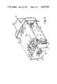
- FIG. 3is an isometric view of the embodiment of FIG. 1 without the pickup lens and outside covers;
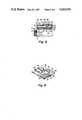
- FIG. 4is an isometric view of the pickup tube and deflection yoke receiving and adjustment structure
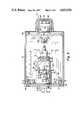
- FIG. 6is a side elevation sectional view of the embodiment of FIG. 1 taken along lines 6--6;
- FIG. 8is a sectional view through the adjustment structure of FIG. 3 taken along lines 8--8;
- camera 10includes a front bracket plate 12 which may be cast metal to which is secured pickup lens assembly 14 and respective upper and lower covers 16 and 18.
- Transformer assembly 20is secured to covers 16 and 18 at the camera rear.
- a decorative coverwhich snaps in place over plate 12 and latches behind assembly 14.
- the adjustment mechanism 44includes tube-like structure 60 which extends from and is normal to plate 12 and has a circular cylindrical cavity 61.
- Structure 60has first and second arcuate side walls 64 and 66 having an axially extending V-shaped opening 62, the opening tapering toward its apex as it approaches plate 12.
- Side wall 64has a screw access slot 68.
- Plate 70connects walls 64 and 66 opposite opening 62.
- Plate 70has an opening 88, a plane outer surface 80 and a circular cylindrical inner surface 70' forming a continuous circular cylindrical surface with walls 64 and 66 defining cavity 61.
- Surface 80is normal to plate 12 and parallel to axis 24.
- a threaded aperture 72, a circular cylindrical aperture 74, and a pair of axial extending grooves 76 and 78, parallel to axis 24,are in plate surface 80.
- Mechanism 44includes a slider 82, which slides on surface 80 in axial directions 95 parallel to axis 24.
- Slider 82FIGS. 4 and 9, includes a rib 83, which is closely received within and slides in groove 78, and a rib 84 which is closely received in and slides in groove 76.
- Slider 82has a boss 86, which moves within plate 70 opening 88.
- Boss 86has an axially extending threaded aperture 87.
- Slider 82has a camming recess 90, located offset from a line through boss 86 and rib 84.
- Recess 90has side walls 106 and 108 and bottom wall 110.
- Elongated slot 92 parallel to axis 24is in wall 110.
- Slider 82has a second slot 94 parallel to ribs 83 and 84.
- Slider 82is movable in directions 95, relative to surface 80 and plate 12.
- Slider 82may be molded from thermoplastic material.
- cam element 96includes a relatively large circular cylindrical camming disc 98 from which extend in respective opposite directions two aligned smaller circular cylindrical discs 100 and 102.
- Discs 100 and 102are concentric about axis 114 offset from the disc 98 central axis.
- Disc 102is a journal which is closely received in aperture 74 for rotation about axis 114.
- Disc 100is a drive member having screwdriver slot 112 and is closely received in slot 92 of slider 82.
- Disc 98is located in slider recess 90, FIG. 9, abuts recess 90 walls 106 and 108, and is captured between surface 80 and slider wall 110, FIG. 4.
- Disc 98slides against and cams the side walls 106 and 108 when rotated. Rotation of the camming element 96 about axis 114 causes the eccentricity of disc 98 relative to axis 114 to displace slider 82 in one of directions 95. Screw 116 passes through slider 82 slot 94 and is threaded to aperture 72 to lock slider 82 in any given axial position as determined by the relative angular orientation of camming element 96.
- Yoke 4is closely slidably received within the cylindrical cavity 134 of member 126, FIGS. 4 and 6, until the yoke wall 56, FIG. 6, abuts flange 128.
- Three screws 131two being shown in FIG. 6, attach flange 128 to the yoke 48 wall 56 via screw apertures 136 in flange 128, FIG. 4.
- the inwardly extending flange 128includes a central aperture 132 for permitting the image from the pickup lens 14, FIG. 1, to be projected onto the pickup tube 46, FIG. 2.
- the member 126 side wallhas an opening 150, FIG. 4, providing access to screw 52, FIG. 6, through the structure 60 slot 68 with a screwdriver.
- openings 140, 142, and 144are each of sufficient length to permit some rotation of the yoke holder 124 about axis 24, e.g., about 10°, and thus permitting fine adjustment of the angular orientation of the pickup tube 46, FIGS. 2 and 6, relative to axis 24.
- the adjustment mechanismpermits removal of the yoke assembly 47 without disturbing the back focus settings as will be described.
- the electronics for operating the camera 10are on the two printed circuit boards 41 and 42, FIG. 2.
- Printed circuit board 41which is optional, is screwed to ears 34 and 38, FIG. 5, and board 42 is screwed to ears 36 and 40 straddling the tube, yoke, and yoke holder assembly 47.
- Board 41, FIGS. 2 and 3has a clearance opening 41' for slider 82.
- the power supplypowers the circuitry on the printed circuit boards and the tube 46 (indirectly) by conductors (not shown). Slots 195, FIG. 5, receive an edge of printed circuit board 41 and slots 194 receive an edge of printed circuit board 42.
- the transformer housing 186abuts the rear edges of the covers 16 and 18, FIGS. 1 and 6. Legs 188 and 190 abut the inner respective surfaces of the covers 16 and 18.
- Transformer assembly 20FIGS. 2, 5, and 7, is aligned between the covers to receive respective cover stanchions 162' and 162 through legs 188 and 190 prior to the assembly of the covers 16 and 18.
- the transformer assembly 20 and all of the elements in the cameraare securely fastened in place.
- the bracket 160includes two upstanding ears 174, FIGS. 2, 5, and 7, which overlay respective stanchions 167 and 168.
- Bracket 160includes boss 176 having a threaded aperture 177.
- Boss 176is positioned in cover opening 170 (see boss 176' shown in connection with plate 160' associated with cover 16).
- the threaded aperture 177mounts the camera to a mating threaded stud (not shown) on a support.
- One ear 174 of bracket 160is located between stanchion 167 and plate 12 ear 28, FIG. 7.
- the other ear 174is between cover 16 stanchion 168 and ear 32 of plate 12.
- the ears 174' of the upper cover bracket 160'are similarly sandwiched between respective cover 18 stanchions 167' and 168' and respective ears 26 and 30 of plate 12.
- Screw 182 FIGS. 2 and 7is passed through the apertures of stanchion 168', a bracket 160' ear 174', plate 12 ears 30 and 32, an ear 174 of bracket 160 and then tapped into the aperture of cover 18 stanchion 168.
- Screw 180is secured to similar elements on the different parts and tapped into stanchion 167. This locks the cover 16 to the cover 18 and the corresponding brackets 160, 160' to the ears 26, 28, 30, and 32, FIGS. 2 and 5, securing the covers to plate 12.
- the stanchions 162 and 162' of the respective covers 18 and 16abut. These stanchions pass through corresponding openings in the printed circuit boards 41 and 42 and holes 188' and 190' of transformer housing 120, FIG. 7. Screw 184, FIGS. 2 and 7, passes through stanchion 162' and is tapped into the aperture of stanchion 162.
- cover 16includes a pair of adjustment access apertures 200 and 202.
- Aperture 200provides access to slider 82 locking screw 116, FIGS. 2 and 3, and aperture 202 provides access to camming element 96.
- Bracket 160', FIG. 2also includes access apertures 201 and 203 aligned with respective apertures 200 and 202.
- the tube and yoke assembly 47, FIGS. 6 and 7can be back focussed with the covers 16 and 18 and the transformer assembly 20 attached.
- the pickup tube 46may be disassembled from the yoke 48, FIG. 4, via access aperture 68 in structure 60.
- various portions of the assemblymay be disassembled and/or adjusted using relatively few components and few screws.
- the angular position of the tube 46, FIG. 2may be adjusted to any one of three orientations as determined by the locations of slotted openings 140, 142, and 144 in yoke holder 124, FIG. 4.
- the picture presented by the tube 46, FIG. 2may be placed at three orientations ⁇ 90° within a ⁇ 5° adjustment range at each orientation as determined by the length of slots 140, 142, and 144, FIG. 4, relative to a given housing orientation.
- the yoke holder 124by being manually angularly adjustable by grasping flange 130, is easily adjusted. This is a relatively difficult adjustment in the limited space environment of some prior art cameras.
- the yoke holder 124closely receives the yoke and, in turn, is closely received within the structure 60 cylindrical cavity to preclude undesirable play or movement between these various elements in a direction normal to axis 24.
- the pickup tubemay be axially displaced with a relatively simple adjustment and by loosening only one screw 116.
- the yoke holder assembly 47is removed by loosening only one screw 122.
- the yoke 48 position relative to the yoke holderis predetermined by the screws 132 (FIG. 6) which are located in mating screw holes in the yoke 48 front face. This accurately aligns the yoke relative to the holder 124.
Landscapes
- Engineering & Computer Science (AREA)
- Multimedia (AREA)
- Signal Processing (AREA)
- Studio Devices (AREA)
Abstract
Description
This invention relates to a television camera structure and more particularly, to a back focussing structure.
In a television camera the image pickup tube is carried in a television deflection yoke comprising windings contained within an outer circular cylindrical electrical shield. The tube is secured to the yoke by a screw operated hose type clamp. The camera also includes a housing to which the image pickup lens is attached, the pickup lens defining an optical pickup axis. The housing includes structure for securing the yoke and pickup tube on the optical axis.
One requirement of this assembly is that the pickup tube be "back" focussed relative to the pickup lens during camera assembly. What this means is that the tube and yoke assembly are required to be displaced relative to the lens parallel to the lens optical axis to locate the pickup tube target at the focal plane of the lens. The pickup lens also includes self-contained focussing elements for "front" focussing during normal use of the camera by the camera operator.
An additional requirement of camera assembly is that the tube be accurately angularly oriented relative to the pickup lens to position the focussed image on the target of the pickup tube. By way of example, in a surveillance application, the camera housing may be mounted in a number of positions; however, the tube must be positioned within the housing so as to produce a picture which is not rotated 90° or 180° with respect to the image. This adjustment requires angular positioning of the tube relative to the lens. Any misorientation of the pickup tube in the angular direction about the optical axis will produce a correspondingly misoriented picture. Therefore, the back focussing mechanism should consider both alignments.
In U.S. Pat. No. 4,369,470 a lever adjustment device is described for focussing the pickup tube relative to the pickup lens. To insure proper angular orientation of the tube relative to the axis, a bracket is cemented to the yoke shield, the bracket having a given angular orientation relative to the optical axis to prevent pickup tube rotation. However, this arrangement is not entirely satisfactory for those implementations which require the camera housing to be positioned in more than one angular orientation.
In U.S. Pat. No. 2,681,497 a television camera assembly is disclosed in which the housing includes a pair of saddle members and a bell crank lever which bears against an associated annular member to hold the pickup tube in position. The tube can be rotated within the saddle members and moved longitudinally to adjust its axial position. The pickup tube, saddle members, lever, amplifiers, and other ancillary equipment are all mounted in a box. If it is necessary to change a pickup tube, this system requires replacement of the box with another box in which the pickup tube, amplifier, and ancillary equipment have been preadjusted. This latter construction is rather complex, costly, and cumbersome to implement especially in the case of a simple tube replacement or adjustment.
In other implementations, tube replacement is relatively difficult, requiring disassembly of the prefocussed tube assembly disrupting the back focussed alignment. Other arrangements do not readily lend themselves to rapid simple angular alignment of the tube. Still other arrangements place the tube in complex structures making access to the tube for replacement or alignment relative to the pickup lens difficult. No single prior art structure addresses all of the alignment requirements of the tube with ease and simplicity.
According to the present invention, a television camera structure is adapted to receive a pickup tube and deflection yoke coupled to the tube on a given optical axis. The structure comprises a lens support bracket for receiving and securing a pickup lens on the axis, the lens for projecting an image onto the received tube. A circular cylindrical member is adapted to receive and secure a circular cylindrical yoke therein. Locating means is secured to the bracket adapted for axially and rotationally receiving the yoke securing member so that the member can be moved relative to the bracket in a direction parallel to the axis and can be rotated relative to the bracket about the axis to a plurality of predetermined angular positions. Yoke displacement means coupled to the locating means are adapted to secure the member thereto in the predetermined angular position. The displacement means axially incrementally moves the angularly located member relative to the bracket in a direction parallel to the axis to set the back focus position of the pickup tube. Tube replacement can be made by removing the tube without upsetting the displacement means position.
In the drawing:
FIG. 1 is an isometric view of a camera structure according to one embodiment of the present invention;
FIG. 2 is an exploded isometric view of the embodiment of FIG. 1;
FIG. 3 is an isometric view of the embodiment of FIG. 1 without the pickup lens and outside covers;
FIG. 4 is an isometric view of the pickup tube and deflection yoke receiving and adjustment structure;
FIG. 5 is a plan view, partially in section, of the camera of FIG. 1;
FIG. 6 is a side elevation sectional view of the embodiment of FIG. 1 taken along lines 6--6;
FIG. 7 is a side elevation sectional view taken along lines 7--7 of FIG. 1;
FIG. 8 is a sectional view through the adjustment structure of FIG. 3 taken along lines 8--8; and
FIG. 9 is an underside isometric view of the slider element employed in the embodiment of FIG. 3.
In FIG. 1,camera 10 includes afront bracket plate 12 which may be cast metal to which is secured pickup lens assembly 14 and respective upper andlower covers Transformer assembly 20 is secured to covers 16 and 18 at the camera rear. Not shown is a decorative cover which snaps in place overplate 12 and latches behind assembly 14.
In more detail,plate 12, FIG. 3, includes a pickuplens receiving projection 21 having an internally threadedaperture 22 for receiving and aligning the optic axis of pickup lens assembly 14, FIG. 1, concentric withaxis 24.Plate 12, FIGS. 3 and 5, includes four cantilevered aperturedears ears ears Ears ears Plate 12, FIG. 5, includes cantilevered aperturedears Ear pair ear pair 36 and 40 is coplanar.
In FIGS. 2 and 4, back focussingadjustment mechanism 44 is secured toplate 12.Mechanism 44 aligns tube and yoke assembly 47 on theoptic axis 24 and adjusts the axial position of tube and yoke assembly 47 parallel toaxis 24 for back focussing the tube relative to lens assembly 14, FIG. 1.Mechanism 44 also permits rotation of assembly 47 about theoptic axis 24.
Theadjustment mechanism 44, FIG. 4, includes tube-like structure 60 which extends from and is normal toplate 12 and has a circularcylindrical cavity 61.Structure 60 has first and secondarcuate side walls shaped opening 62, the opening tapering toward its apex as it approachesplate 12.Side wall 64 has ascrew access slot 68.Plate 70 connectswalls opposite opening 62.Plate 70 has anopening 88, a planeouter surface 80 and a circular cylindrical inner surface 70' forming a continuous circular cylindrical surface withwalls cavity 61.Surface 80 is normal toplate 12 and parallel toaxis 24. A threaded aperture 72, a circularcylindrical aperture 74, and a pair of axial extendinggrooves 76 and 78, parallel toaxis 24, are inplate surface 80.
In FIG. 4,cam element 96 includes a relatively large circularcylindrical camming disc 98 from which extend in respective opposite directions two aligned smaller circularcylindrical discs Discs axis 114 offset from thedisc 98 central axis.Disc 102 is a journal which is closely received inaperture 74 for rotation aboutaxis 114.Disc 100 is a drive member having screwdriver slot 112 and is closely received inslot 92 ofslider 82.Disc 98 is located inslider recess 90, FIG. 9, abutsrecess 90walls surface 80 andslider wall 110, FIG. 4.
In FIGS. 2 and 4, tube and yoke assembly 47 includesyoke holder 124,pickup tube 46 andyoke 48.Yoke holder 124 comprises a circular cylindrical tube-like member 126, a radially inwardly extendingflange 128 at one end and a radially outwardly extendingflange 130 at the other end.Holder 124 may be thin walled molded thermoplastic material.
In FIGS. 2, 6, and 7pickup tube 46 having a circular cylindrical glass envelope and a longitudinal axis 24' is closely received in the circular cylindrical core ofyoke 48. Theyoke 48 includes a plurality of windings (not shown) and anouter shield 49.Shield 49 has a circular cylindricalouter surface 54 concentric with the received tube axis 24'. In FIG. 6,tube 46 is closely received in and clamped toyoke 48 by an annular hose-type clamp 50 via screw 52, the tube pickup window (not shown) abutting the yokefront face wall 56.Wall 56 has an opening to permit an image from lens assembly 14, FIG. 1, to be projected onto the pickup tube through the pickup window.
The length ofmember 126, FIGS. 4 and 6, indirections 95 is sufficient to permit axial displacement within the expected adjustment range needed to back focus the attachedpickup tube 46. The amount of the adjustment range may be set in accordance with a given implementation.Element 96, FIG. 4, has sufficient eccentricity to moveslider 82 indirections 95 an amount necessary to achieve anticipated focussing of thetube 46 relative to the focal plane of the pickup lens of assembly 14, FIG. 1.
Should the focussed and correctly orientedtube 46 need to be replaced, it is required that the clamp 50, FIG. 6, be loosened so that the tube can be removed from theyoke 48. It is also desirable that thetube 46 be removed fromyoke 48 without disturbing the yoke orientation and focus position. To removetube 46, FIG. 4, screw 52 is loosened viaaccess slot 68 inwall 60 andhole 150 inholder 124. This permits simple tube replacement without the need for refocussing the tube sinceyoke holder 124 need not be disturbed. The replacement tube is oriented angularly inyoke holder 124 manually and then locked toyoke 48 via screw 52. In some cases,holder 124 may be disturbed angularly in replacing a tube. This is acceptable as it is a simple procedure to relocate the angular position of the assembly.
At certain other times it is desired to remove the yoke and tube assembly 47 without disturbing their preadjusted focussed position. The adjustment mechanism, FIG. 4, permits removal of the yoke assembly 47 without disturbing the back focus settings as will be described.
The electronics for operating thecamera 10 are on the two printedcircuit boards circuit board 41, which is optional, is screwed toears board 42 is screwed toears 36 and 40 straddling the tube, yoke, and yoke holder assembly 47.Board 41, FIGS. 2 and 3, has a clearance opening 41' forslider 82.
Thebracket 160 includes twoupstanding ears 174, FIGS. 2, 5, and 7, which overlayrespective stanchions Bracket 160 includesboss 176 having a threadedaperture 177.Boss 176 is positioned in cover opening 170 (see boss 176' shown in connection with plate 160' associated with cover 16). The threadedaperture 177 mounts the camera to a mating threaded stud (not shown) on a support. Oneear 174 ofbracket 160 is located betweenstanchion 167 andplate 12ear 28, FIG. 7. Theother ear 174 is betweencover 16stanchion 168 andear 32 ofplate 12. The ears 174' of the upper cover bracket 160' are similarly sandwiched betweenrespective cover 18 stanchions 167' and 168' andrespective ears plate 12.Screw 182, FIGS. 2 and 7, is passed through the apertures of stanchion 168', a bracket 160' ear 174',plate 12ears ear 174 ofbracket 160 and then tapped into the aperture ofcover 18stanchion 168.Screw 180 is secured to similar elements on the different parts and tapped intostanchion 167. This locks thecover 16 to thecover 18 and thecorresponding brackets 160, 160' to theears
Thestanchions 162 and 162' of the respective covers 18 and 16 abut. These stanchions pass through corresponding openings in the printedcircuit boards Screw 184, FIGS. 2 and 7, passes through stanchion 162' and is tapped into the aperture ofstanchion 162.
In FIG. 1, cover 16 includes a pair ofadjustment access apertures Aperture 200 provides access toslider 82 lockingscrew 116, FIGS. 2 and 3, andaperture 202 provides access tocamming element 96. Bracket 160', FIG. 2, also includesaccess apertures respective apertures covers transformer assembly 20 attached. In addition, by merely disassembling thecovers transformer assembly 20 which is modular, thepickup tube 46 may be disassembled from theyoke 48, FIG. 4, viaaccess aperture 68 instructure 60. Thus, various portions of the assembly may be disassembled and/or adjusted using relatively few components and few screws.
The angular position of thetube 46, FIG. 2, may be adjusted to any one of three orientations as determined by the locations of slottedopenings yoke holder 124, FIG. 4. Thus, the picture presented by thetube 46, FIG. 2, may be placed at three orientations ±90° within a ±5° adjustment range at each orientation as determined by the length ofslots yoke holder 124 by being manually angularly adjustable by graspingflange 130, is easily adjusted. This is a relatively difficult adjustment in the limited space environment of some prior art cameras.
It is to be understood that theyoke holder 124 closely receives the yoke and, in turn, is closely received within thestructure 60 cylindrical cavity to preclude undesirable play or movement between these various elements in a direction normal toaxis 24. The pickup tube may be axially displaced with a relatively simple adjustment and by loosening only onescrew 116. By removing thecovers 16 and 18 (thetransformer assembly 20 may remain in place), the yoke holder assembly 47 is removed by loosening only onescrew 122. Theyoke 48 position relative to the yoke holder is predetermined by the screws 132 (FIG. 6) which are located in mating screw holes in theyoke 48 front face. This accurately aligns the yoke relative to theholder 124.
Claims (15)
1. A television camera structure adapted to receive an image pickup tube and a yoke coupled to the tube on a given optical axis comprising:
a planar lens support bracket for receiving and securing an image pickup lens on said axis, said lens for projecting said image onto said received tube;
a circular cylindrical member adapted to receive and secure said yoke thereto;
member locating means secured to and cantilevered from said bracket adapted for axially and rotationally receiving said yoke securing member so that said member can be moved relative to the bracket in a direction parallel to said axis and can be rotated relative to the bracket about said axis to a plurality of predetermined angular positions;
yoke displacement means coupled to said locating means adapted to secure the member thereto in the predetermined angular position, said displacement means for axially incrementally moving said angularly located member relative to said bracket in a direction parallel to said axis to set back focus position of the pickup tube; and
printed circuit board connecting means depending from the bracket for cantilevering at least one printed circuit board adjacent a board edge from the bracket parallel to said axis.
2. The structure of claim 1 wherein said member and said yoke displacement include cam means for camming said member in said parallel direction and means adapted to settably secure said cammed member in an angular extent relative to said axis of at least about 90°.
3. The structure of claim 1 wherein said member includes a flange portion and a cylindrical body portion, said displacement means including a slide element secured to said flange portion and slidably secured to said member locating means for movement parallel to said axis, and means coupled to the bracket and element for displacing said element relative to said bracket.
4. The structure of claim 1 wherein said yoke comprises a cylindrical body having an end face, said member comprising a cylindrical body adapted to embrace said yoke body and an inwardly directed flange adapted to abut and be secured to said end face.
5. The structure of claim 1 further including camera housing means cantilevered from and embracing said bracket.
6. The structure of claim 5 further including transformer housing means cantilevered from said camera housing means at a location distal said bracket, said transformer housing means and said bracket including means for securing at least one printed circuit board thereto.
7. The structure of claim 1 wherein said yoke displacement means comprises a slide element slidably secured to the bracket and having a camming slot and a cam member in said slot and rotatably secured to said bracket for camming said element relative to said bracket in response to rotation of said cam member, said yoke receiving and securing member being secured to said element for axial displacement therewith.
8. A television camera structure comprising:
a plate member having an optical aperture lying on an axis;
yoke holder receptacle means secured to said member adjacent to said aperture, said receptacle means defining a circular cylindrical cavity concentric with said axis;
cam means secured to said receptacle means for reciprocative displacement parallel to said axis;
a yoke holder adapted to receive a pickup tube yoke closely received in said receptacle means cavity and secured to said cam means for axial displacement parallel to said axis in response to said reciprocative displacement; and
means for securing said holder in a selected one of a plurality of anglar orientations relative to said axis in an angular extent of at least 90 degrees.
9. The structure of claim 8 wherein said receptacle means includes a semicircular cylindrical member extending from said plate member, a slide element secured to said cylindrical member for axial displacement parallel to said axis, and a cam element movably secured to said cylindrical member and said slide element for axially displacing said slide element relative to said cylindrical member in response to movement of said cam element.
10. The structure of claim 9 wherein said yoke holder includes a circular cylindrical housing closely slidably received in said cylindrical cavity and an outwardly extending ring-like flange member adapted to be secured to said slide element.
11. The structure of claim 10 wherein said flange member is adapted to be secured in a selected one of a plurality of angular orientations relative to said axis.
12. The structure of claim 8 including connector means attached to said plate member for cantilevering at least one printed circuit board at an edge thereof and a housing at an end thereof from said plate member.
13. The structure of claim 8 wherein said yoke holder includes flange means adapted to be juxtaposed with and secured to a face of a pickup tube yoke.
14. A television camera structure comprising:
a substantially planar image pickup lens bracket having an opening defining an optical axis for said lens;
tube receiving means cantilevered from the bracket for rotationally and axially securing a pickup tube and yoke assembly to said bracket coaxial with said optical axis, said tube receiving means including a yoke securing member adapted to receive the yoke assembly and pickup tube, said member being rotationally and axially movably attached to said tube receiving means;
means for securing at least one printed circuit board at one end thereof cantilevered to said bracket in spaced relation to and straddling said tube receiving means;
power supply housing means for securing the other end of said at least one circuit board in said spaced relation; and
a pair of facing covers secured at one end to and cantilevered from said bracket and at the other end to each other and adapted to secure said power supply housing means thereto at said other end.
15. The sturcture of claim 14 wherein said housing means includes latch means for releasably securing power supply means thereto.
Priority Applications (1)
| Application Number | Priority Date | Filing Date | Title |
|---|---|---|---|
| US06/672,959US4652930A (en) | 1984-11-19 | 1984-11-19 | Television camera structure |
Applications Claiming Priority (1)
| Application Number | Priority Date | Filing Date | Title |
|---|---|---|---|
| US06/672,959US4652930A (en) | 1984-11-19 | 1984-11-19 | Television camera structure |
Publications (1)
| Publication Number | Publication Date |
|---|---|
| US4652930Atrue US4652930A (en) | 1987-03-24 |
Family
ID=24700738
Family Applications (1)
| Application Number | Title | Priority Date | Filing Date |
|---|---|---|---|
| US06/672,959Expired - Fee RelatedUS4652930A (en) | 1984-11-19 | 1984-11-19 | Television camera structure |
Country Status (1)
| Country | Link |
|---|---|
| US (1) | US4652930A (en) |
Cited By (40)
| Publication number | Priority date | Publication date | Assignee | Title |
|---|---|---|---|---|
| US4803557A (en)* | 1988-01-11 | 1989-02-07 | Eastman Kodak Company | Adjustable mount for image sensor |
| US5640207A (en)* | 1993-05-19 | 1997-06-17 | Rahmouni; Gilbert | Camera for high-speed imaging |
| US5729291A (en)* | 1991-06-18 | 1998-03-17 | Canon Kabushiki Kaisha | Video camera with compact arrangement of parts |
| US6354749B1 (en) | 1998-09-09 | 2002-03-12 | Videolarm, Inc. | Housing for surveillance camera |
| US6375369B1 (en)* | 1999-04-22 | 2002-04-23 | Videolarm, Inc. | Housing for a surveillance camera |
| USD460773S1 (en) | 2000-10-23 | 2002-07-23 | Pelco | Notched camera case |
| USD474794S1 (en) | 2002-07-18 | 2003-05-20 | Sony Corporation | Video camera |
| US20030095800A1 (en)* | 2001-11-21 | 2003-05-22 | Thales Avionics In-Flights Systems, Llc | Universal security camera |
| US6735382B2 (en) | 2000-04-04 | 2004-05-11 | Videolarm, Inc. | Pressurized camera housing |
| US20060098117A1 (en)* | 2004-11-11 | 2006-05-11 | Hideaki Kajihara | Monitoring camera |
| US20060282866A1 (en)* | 2005-06-13 | 2006-12-14 | Top Eight Industrial Corp. | Web camera |
| WO2011146652A1 (en)* | 2010-05-19 | 2011-11-24 | Flir Systems, Inc. | Infrared camera assembly systems and methods |
| WO2020023543A1 (en)* | 2018-07-24 | 2020-01-30 | Magic Leap, Inc. | Viewing device with dust seal integration |
| US10878235B2 (en) | 2015-02-26 | 2020-12-29 | Magic Leap, Inc. | Apparatus for a near-eye display |
| US10914949B2 (en) | 2018-11-16 | 2021-02-09 | Magic Leap, Inc. | Image size triggered clarification to maintain image sharpness |
| US11092812B2 (en) | 2018-06-08 | 2021-08-17 | Magic Leap, Inc. | Augmented reality viewer with automated surface selection placement and content orientation placement |
| US11112862B2 (en) | 2018-08-02 | 2021-09-07 | Magic Leap, Inc. | Viewing system with interpupillary distance compensation based on head motion |
| US11187923B2 (en) | 2017-12-20 | 2021-11-30 | Magic Leap, Inc. | Insert for augmented reality viewing device |
| US11189252B2 (en) | 2018-03-15 | 2021-11-30 | Magic Leap, Inc. | Image correction due to deformation of components of a viewing device |
| US11199713B2 (en) | 2016-12-30 | 2021-12-14 | Magic Leap, Inc. | Polychromatic light out-coupling apparatus, near-eye displays comprising the same, and method of out-coupling polychromatic light |
| US11200870B2 (en) | 2018-06-05 | 2021-12-14 | Magic Leap, Inc. | Homography transformation matrices based temperature calibration of a viewing system |
| US11204491B2 (en) | 2018-05-30 | 2021-12-21 | Magic Leap, Inc. | Compact variable focus configurations |
| US11210808B2 (en) | 2016-12-29 | 2021-12-28 | Magic Leap, Inc. | Systems and methods for augmented reality |
| US11216086B2 (en) | 2018-08-03 | 2022-01-04 | Magic Leap, Inc. | Unfused pose-based drift correction of a fused pose of a totem in a user interaction system |
| US11280937B2 (en) | 2017-12-10 | 2022-03-22 | Magic Leap, Inc. | Anti-reflective coatings on optical waveguides |
| US11425189B2 (en) | 2019-02-06 | 2022-08-23 | Magic Leap, Inc. | Target intent-based clock speed determination and adjustment to limit total heat generated by multiple processors |
| US11445232B2 (en) | 2019-05-01 | 2022-09-13 | Magic Leap, Inc. | Content provisioning system and method |
| US11510027B2 (en) | 2018-07-03 | 2022-11-22 | Magic Leap, Inc. | Systems and methods for virtual and augmented reality |
| US11514673B2 (en) | 2019-07-26 | 2022-11-29 | Magic Leap, Inc. | Systems and methods for augmented reality |
| US11567324B2 (en) | 2017-07-26 | 2023-01-31 | Magic Leap, Inc. | Exit pupil expander |
| US11579441B2 (en) | 2018-07-02 | 2023-02-14 | Magic Leap, Inc. | Pixel intensity modulation using modifying gain values |
| US11598651B2 (en) | 2018-07-24 | 2023-03-07 | Magic Leap, Inc. | Temperature dependent calibration of movement detection devices |
| US11737832B2 (en) | 2019-11-15 | 2023-08-29 | Magic Leap, Inc. | Viewing system for use in a surgical environment |
| US11762623B2 (en) | 2019-03-12 | 2023-09-19 | Magic Leap, Inc. | Registration of local content between first and second augmented reality viewers |
| US11856479B2 (en) | 2018-07-03 | 2023-12-26 | Magic Leap, Inc. | Systems and methods for virtual and augmented reality along a route with markers |
| US11885871B2 (en) | 2018-05-31 | 2024-01-30 | Magic Leap, Inc. | Radar head pose localization |
| US12016719B2 (en) | 2018-08-22 | 2024-06-25 | Magic Leap, Inc. | Patient viewing system |
| US12033081B2 (en) | 2019-11-14 | 2024-07-09 | Magic Leap, Inc. | Systems and methods for virtual and augmented reality |
| US12044851B2 (en) | 2018-12-21 | 2024-07-23 | Magic Leap, Inc. | Air pocket structures for promoting total internal reflection in a waveguide |
| US12164978B2 (en) | 2018-07-10 | 2024-12-10 | Magic Leap, Inc. | Thread weave for cross-instruction set architecture procedure calls |
Citations (9)
| Publication number | Priority date | Publication date | Assignee | Title |
|---|---|---|---|---|
| GB598517A (en)* | 1945-11-07 | 1948-02-19 | Avimo Ltd | Improvements relating to cathode ray tube holders |
| US2681947A (en)* | 1948-12-17 | 1954-06-22 | Pye Ltd | Television camera assembly |
| US3008002A (en)* | 1957-12-24 | 1961-11-07 | Pye Ltd | Pick-up tube mounting arrangement |
| US3973231A (en)* | 1974-08-27 | 1976-08-03 | Fuji Photo Optical Co., Ltd. | Position adjusting device for image pickup tube coil assembly |
| US4228458A (en)* | 1977-05-31 | 1980-10-14 | Fuji Photo Optical Co., Ltd. | Optical color-separation system for use in a color television camera |
| US4369470A (en)* | 1979-12-13 | 1983-01-18 | U.S. Philips Corporation | Play-free focusing mechanism for a television camera |
| US4485407A (en)* | 1981-11-07 | 1984-11-27 | Grundig E. M.V. | Television camera for indoor and outdoor use |
| US4499504A (en)* | 1981-03-31 | 1985-02-12 | Canon Kabushiki Kaisha | Video system |
| US4534632A (en)* | 1984-04-10 | 1985-08-13 | Andre Laviolette | Camera-protecting apparatus including a fan for deflecting particles |
- 1984
- 1984-11-19USUS06/672,959patent/US4652930A/ennot_activeExpired - Fee Related
Patent Citations (9)
| Publication number | Priority date | Publication date | Assignee | Title |
|---|---|---|---|---|
| GB598517A (en)* | 1945-11-07 | 1948-02-19 | Avimo Ltd | Improvements relating to cathode ray tube holders |
| US2681947A (en)* | 1948-12-17 | 1954-06-22 | Pye Ltd | Television camera assembly |
| US3008002A (en)* | 1957-12-24 | 1961-11-07 | Pye Ltd | Pick-up tube mounting arrangement |
| US3973231A (en)* | 1974-08-27 | 1976-08-03 | Fuji Photo Optical Co., Ltd. | Position adjusting device for image pickup tube coil assembly |
| US4228458A (en)* | 1977-05-31 | 1980-10-14 | Fuji Photo Optical Co., Ltd. | Optical color-separation system for use in a color television camera |
| US4369470A (en)* | 1979-12-13 | 1983-01-18 | U.S. Philips Corporation | Play-free focusing mechanism for a television camera |
| US4499504A (en)* | 1981-03-31 | 1985-02-12 | Canon Kabushiki Kaisha | Video system |
| US4485407A (en)* | 1981-11-07 | 1984-11-27 | Grundig E. M.V. | Television camera for indoor and outdoor use |
| US4534632A (en)* | 1984-04-10 | 1985-08-13 | Andre Laviolette | Camera-protecting apparatus including a fan for deflecting particles |
Cited By (74)
| Publication number | Priority date | Publication date | Assignee | Title |
|---|---|---|---|---|
| US4803557A (en)* | 1988-01-11 | 1989-02-07 | Eastman Kodak Company | Adjustable mount for image sensor |
| US5729291A (en)* | 1991-06-18 | 1998-03-17 | Canon Kabushiki Kaisha | Video camera with compact arrangement of parts |
| US5640207A (en)* | 1993-05-19 | 1997-06-17 | Rahmouni; Gilbert | Camera for high-speed imaging |
| US6354749B1 (en) | 1998-09-09 | 2002-03-12 | Videolarm, Inc. | Housing for surveillance camera |
| US6375369B1 (en)* | 1999-04-22 | 2002-04-23 | Videolarm, Inc. | Housing for a surveillance camera |
| US6735382B2 (en) | 2000-04-04 | 2004-05-11 | Videolarm, Inc. | Pressurized camera housing |
| USD460773S1 (en) | 2000-10-23 | 2002-07-23 | Pelco | Notched camera case |
| US20060268435A1 (en)* | 2001-11-21 | 2006-11-30 | Thales Avionics, Inc. | Universal security camera |
| US7649696B2 (en) | 2001-11-21 | 2010-01-19 | Thales Avionics, Inc. | Universal security camera |
| US6824317B2 (en)* | 2001-11-21 | 2004-11-30 | Thales Avionics, Inc. | Universal security camera |
| US20050063696A1 (en)* | 2001-11-21 | 2005-03-24 | Thales Avionics, Inc. | Universal security camera |
| US20030095800A1 (en)* | 2001-11-21 | 2003-05-22 | Thales Avionics In-Flights Systems, Llc | Universal security camera |
| US7088525B2 (en) | 2001-11-21 | 2006-08-08 | Thales Avionics, Inc. | Universal security camera |
| US20060268116A1 (en)* | 2001-11-21 | 2006-11-30 | Thales Avionics, Inc. | Universal security camera |
| US7330649B2 (en) | 2001-11-21 | 2008-02-12 | Thales Avionics, Inc. | Universal security camera |
| USD474794S1 (en) | 2002-07-18 | 2003-05-20 | Sony Corporation | Video camera |
| US7583314B2 (en)* | 2004-11-11 | 2009-09-01 | Canon Kabushiki Kaisha | Monitoring camera |
| US20060098117A1 (en)* | 2004-11-11 | 2006-05-11 | Hideaki Kajihara | Monitoring camera |
| US20060282866A1 (en)* | 2005-06-13 | 2006-12-14 | Top Eight Industrial Corp. | Web camera |
| CN102986207A (en)* | 2010-05-19 | 2013-03-20 | 菲力尔系统公司 | Infrared camera assembly systems and methods |
| US8118499B2 (en) | 2010-05-19 | 2012-02-21 | LIR Systems, Inc. | Infrared camera assembly systems and methods |
| WO2011146652A1 (en)* | 2010-05-19 | 2011-11-24 | Flir Systems, Inc. | Infrared camera assembly systems and methods |
| CN102986207B (en)* | 2010-05-19 | 2016-11-16 | 菲力尔系统公司 | Infrared camera assembly systems and methods |
| US10878235B2 (en) | 2015-02-26 | 2020-12-29 | Magic Leap, Inc. | Apparatus for a near-eye display |
| US11756335B2 (en) | 2015-02-26 | 2023-09-12 | Magic Leap, Inc. | Apparatus for a near-eye display |
| US11347960B2 (en) | 2015-02-26 | 2022-05-31 | Magic Leap, Inc. | Apparatus for a near-eye display |
| US12131500B2 (en) | 2016-12-29 | 2024-10-29 | Magic Leap, Inc. | Systems and methods for augmented reality |
| US11210808B2 (en) | 2016-12-29 | 2021-12-28 | Magic Leap, Inc. | Systems and methods for augmented reality |
| US11790554B2 (en) | 2016-12-29 | 2023-10-17 | Magic Leap, Inc. | Systems and methods for augmented reality |
| US11874468B2 (en) | 2016-12-30 | 2024-01-16 | Magic Leap, Inc. | Polychromatic light out-coupling apparatus, near-eye displays comprising the same, and method of out-coupling polychromatic light |
| US11199713B2 (en) | 2016-12-30 | 2021-12-14 | Magic Leap, Inc. | Polychromatic light out-coupling apparatus, near-eye displays comprising the same, and method of out-coupling polychromatic light |
| US11567324B2 (en) | 2017-07-26 | 2023-01-31 | Magic Leap, Inc. | Exit pupil expander |
| US11927759B2 (en) | 2017-07-26 | 2024-03-12 | Magic Leap, Inc. | Exit pupil expander |
| US11953653B2 (en) | 2017-12-10 | 2024-04-09 | Magic Leap, Inc. | Anti-reflective coatings on optical waveguides |
| US12298473B2 (en) | 2017-12-10 | 2025-05-13 | Magic Leap, Inc. | Anti-reflective coatings on optical waveguides |
| US11280937B2 (en) | 2017-12-10 | 2022-03-22 | Magic Leap, Inc. | Anti-reflective coatings on optical waveguides |
| US12366769B2 (en) | 2017-12-20 | 2025-07-22 | Magic Leap, Inc. | Insert for augmented reality viewing device |
| US11187923B2 (en) | 2017-12-20 | 2021-11-30 | Magic Leap, Inc. | Insert for augmented reality viewing device |
| US11762222B2 (en) | 2017-12-20 | 2023-09-19 | Magic Leap, Inc. | Insert for augmented reality viewing device |
| US11189252B2 (en) | 2018-03-15 | 2021-11-30 | Magic Leap, Inc. | Image correction due to deformation of components of a viewing device |
| US11908434B2 (en) | 2018-03-15 | 2024-02-20 | Magic Leap, Inc. | Image correction due to deformation of components of a viewing device |
| US11776509B2 (en) | 2018-03-15 | 2023-10-03 | Magic Leap, Inc. | Image correction due to deformation of components of a viewing device |
| US11204491B2 (en) | 2018-05-30 | 2021-12-21 | Magic Leap, Inc. | Compact variable focus configurations |
| US11885871B2 (en) | 2018-05-31 | 2024-01-30 | Magic Leap, Inc. | Radar head pose localization |
| US11200870B2 (en) | 2018-06-05 | 2021-12-14 | Magic Leap, Inc. | Homography transformation matrices based temperature calibration of a viewing system |
| US11092812B2 (en) | 2018-06-08 | 2021-08-17 | Magic Leap, Inc. | Augmented reality viewer with automated surface selection placement and content orientation placement |
| US12001013B2 (en) | 2018-07-02 | 2024-06-04 | Magic Leap, Inc. | Pixel intensity modulation using modifying gain values |
| US11579441B2 (en) | 2018-07-02 | 2023-02-14 | Magic Leap, Inc. | Pixel intensity modulation using modifying gain values |
| US11856479B2 (en) | 2018-07-03 | 2023-12-26 | Magic Leap, Inc. | Systems and methods for virtual and augmented reality along a route with markers |
| US11510027B2 (en) | 2018-07-03 | 2022-11-22 | Magic Leap, Inc. | Systems and methods for virtual and augmented reality |
| US12164978B2 (en) | 2018-07-10 | 2024-12-10 | Magic Leap, Inc. | Thread weave for cross-instruction set architecture procedure calls |
| US12379981B2 (en) | 2018-07-10 | 2025-08-05 | Magic Leap, Inc. | Thread weave for cross-instruction set architectureprocedure calls |
| US12247846B2 (en) | 2018-07-24 | 2025-03-11 | Magic Leap, Inc. | Temperature dependent calibration of movement detection devices |
| US11624929B2 (en) | 2018-07-24 | 2023-04-11 | Magic Leap, Inc. | Viewing device with dust seal integration |
| WO2020023543A1 (en)* | 2018-07-24 | 2020-01-30 | Magic Leap, Inc. | Viewing device with dust seal integration |
| US11598651B2 (en) | 2018-07-24 | 2023-03-07 | Magic Leap, Inc. | Temperature dependent calibration of movement detection devices |
| US11630507B2 (en) | 2018-08-02 | 2023-04-18 | Magic Leap, Inc. | Viewing system with interpupillary distance compensation based on head motion |
| US11112862B2 (en) | 2018-08-02 | 2021-09-07 | Magic Leap, Inc. | Viewing system with interpupillary distance compensation based on head motion |
| US11609645B2 (en) | 2018-08-03 | 2023-03-21 | Magic Leap, Inc. | Unfused pose-based drift correction of a fused pose of a totem in a user interaction system |
| US12254141B2 (en) | 2018-08-03 | 2025-03-18 | Magic Leap, Inc. | Unfused pose-based drift correction of a fused pose of a totem in a user interaction system |
| US11960661B2 (en) | 2018-08-03 | 2024-04-16 | Magic Leap, Inc. | Unfused pose-based drift correction of a fused pose of a totem in a user interaction system |
| US11216086B2 (en) | 2018-08-03 | 2022-01-04 | Magic Leap, Inc. | Unfused pose-based drift correction of a fused pose of a totem in a user interaction system |
| US12016719B2 (en) | 2018-08-22 | 2024-06-25 | Magic Leap, Inc. | Patient viewing system |
| US11521296B2 (en) | 2018-11-16 | 2022-12-06 | Magic Leap, Inc. | Image size triggered clarification to maintain image sharpness |
| US10914949B2 (en) | 2018-11-16 | 2021-02-09 | Magic Leap, Inc. | Image size triggered clarification to maintain image sharpness |
| US12044851B2 (en) | 2018-12-21 | 2024-07-23 | Magic Leap, Inc. | Air pocket structures for promoting total internal reflection in a waveguide |
| US11425189B2 (en) | 2019-02-06 | 2022-08-23 | Magic Leap, Inc. | Target intent-based clock speed determination and adjustment to limit total heat generated by multiple processors |
| US11762623B2 (en) | 2019-03-12 | 2023-09-19 | Magic Leap, Inc. | Registration of local content between first and second augmented reality viewers |
| US12267545B2 (en) | 2019-05-01 | 2025-04-01 | Magic Leap, Inc. | Content provisioning system and method |
| US11445232B2 (en) | 2019-05-01 | 2022-09-13 | Magic Leap, Inc. | Content provisioning system and method |
| US12249035B2 (en) | 2019-07-26 | 2025-03-11 | Magic Leap, Inc. | System and method for augmented reality with virtual objects behind a physical surface |
| US11514673B2 (en) | 2019-07-26 | 2022-11-29 | Magic Leap, Inc. | Systems and methods for augmented reality |
| US12033081B2 (en) | 2019-11-14 | 2024-07-09 | Magic Leap, Inc. | Systems and methods for virtual and augmented reality |
| US11737832B2 (en) | 2019-11-15 | 2023-08-29 | Magic Leap, Inc. | Viewing system for use in a surgical environment |
Similar Documents
| Publication | Publication Date | Title |
|---|---|---|
| US4652930A (en) | Television camera structure | |
| US4803557A (en) | Adjustable mount for image sensor | |
| US10708471B2 (en) | Alignment of a camera system, camera system and alignment aid | |
| US5862428A (en) | Apparatus for detachably mounting a lens filter onto a camera | |
| CA2376414C (en) | Lens mount apparatus for a high definition video camera | |
| US4913527A (en) | Lens focus adjustment means | |
| US5739853A (en) | Device for supporting optical system of television camera and having two spring systems for reducing rattling in two different directions | |
| US11159707B2 (en) | Main body of interchangeable-lens image pickup apparatus, mount apparatus for same, and flange back adjustment member | |
| US7031081B2 (en) | Matte box quick assembly system | |
| JPH078021B2 (en) | Lens mount switching mechanism for TV cameras | |
| EP0452404A1 (en) | Lens adjustment apparatus and universal joint. | |
| US5555051A (en) | Back-focus adjusting device for a video camera | |
| GB2258968A (en) | Aligning image sensor with lens assembly image plane | |
| US3048654A (en) | Television projection tube alignment | |
| US6865035B2 (en) | XY finder | |
| US7072122B2 (en) | Lens apparatus, projection type optical apparatus and projection type image display apparatus | |
| EP0532304B1 (en) | X-ray imaging system with focusing apparatus for a folded collimating lens | |
| JP2000131584A (en) | Television camera device | |
| US3225140A (en) | Combination motion picture and television camera | |
| JP3163052B2 (en) | Stereo microscope | |
| JPH11211992A (en) | Stereoscopic microscope | |
| US3527884A (en) | Demountable system for flying spot scanner | |
| JP2524526Y2 (en) | Laser injection unit | |
| JPS61259599A (en) | Position adjustor for solid image sensor | |
| JPH068580Y2 (en) | Endoscope eyepiece device |
Legal Events
| Date | Code | Title | Description |
|---|---|---|---|
| AS | Assignment | Owner name:RCA CORPORATION, A CORP OF DE Free format text:ASSIGNMENT OF ASSIGNORS INTEREST.;ASSIGNOR:CRAWFORD, CHRISTOPHER L.;REEL/FRAME:004336/0825 Effective date:19841114 Owner name:RCA CORPORATION, A CORP. OF DE,NEW JERSEY Free format text:ASSIGNMENT OF ASSIGNORS INTEREST;ASSIGNOR:CRAWFORD, CHRISTOPHER L.;REEL/FRAME:004336/0825 Effective date:19841114 | |
| FPAY | Fee payment | Year of fee payment:4 | |
| FEPP | Fee payment procedure | Free format text:PAYOR NUMBER ASSIGNED (ORIGINAL EVENT CODE: ASPN); ENTITY STATUS OF PATENT OWNER: LARGE ENTITY | |
| FPAY | Fee payment | Year of fee payment:8 | |
| REMI | Maintenance fee reminder mailed | ||
| LAPS | Lapse for failure to pay maintenance fees | ||
| FP | Lapsed due to failure to pay maintenance fee | Effective date:19990324 | |
| STCH | Information on status: patent discontinuation | Free format text:PATENT EXPIRED DUE TO NONPAYMENT OF MAINTENANCE FEES UNDER 37 CFR 1.362 |