US4652805A - Tactile feedback apparatus for rotary manual input - Google Patents
Tactile feedback apparatus for rotary manual inputDownload PDFInfo
- Publication number
- US4652805A US4652805AUS06/794,432US79443285AUS4652805AUS 4652805 AUS4652805 AUS 4652805AUS 79443285 AUS79443285 AUS 79443285AUS 4652805 AUS4652805 AUS 4652805A
- Authority
- US
- United States
- Prior art keywords
- handwheel
- tactile feedback
- transducer
- brake
- feedback apparatus
- Prior art date
- Legal status (The legal status is an assumption and is not a legal conclusion. Google has not performed a legal analysis and makes no representation as to the accuracy of the status listed.)
- Expired - Lifetime
Links
Images
Classifications
- G—PHYSICS
- G05—CONTROLLING; REGULATING
- G05B—CONTROL OR REGULATING SYSTEMS IN GENERAL; FUNCTIONAL ELEMENTS OF SUCH SYSTEMS; MONITORING OR TESTING ARRANGEMENTS FOR SUCH SYSTEMS OR ELEMENTS
- G05B19/00—Programme-control systems
- G05B19/02—Programme-control systems electric
- G05B19/18—Numerical control [NC], i.e. automatically operating machines, in particular machine tools, e.g. in a manufacturing environment, so as to execute positioning, movement or co-ordinated operations by means of programme data in numerical form
- G05B19/408—Numerical control [NC], i.e. automatically operating machines, in particular machine tools, e.g. in a manufacturing environment, so as to execute positioning, movement or co-ordinated operations by means of programme data in numerical form characterised by data handling or data format, e.g. reading, buffering or conversion of data
- G—PHYSICS
- G05—CONTROLLING; REGULATING
- G05B—CONTROL OR REGULATING SYSTEMS IN GENERAL; FUNCTIONAL ELEMENTS OF SUCH SYSTEMS; MONITORING OR TESTING ARRANGEMENTS FOR SUCH SYSTEMS OR ELEMENTS
- G05B2219/00—Program-control systems
- G05B2219/30—Nc systems
- G05B2219/35—Nc in input of data, input till input file format
- G05B2219/35459—Knob, handle, handwheel delivers pulses, electronic handwheel, digipot
- G—PHYSICS
- G05—CONTROLLING; REGULATING
- G05B—CONTROL OR REGULATING SYSTEMS IN GENERAL; FUNCTIONAL ELEMENTS OF SUCH SYSTEMS; MONITORING OR TESTING ARRANGEMENTS FOR SUCH SYSTEMS OR ELEMENTS
- G05B2219/00—Program-control systems
- G05B2219/30—Nc systems
- G05B2219/37—Measurements
- G05B2219/37396—Tactile feedback, operator feels reaction, force reflection
Definitions
- the field of the inventionis rotary manual input mechanisms and more particularly, tactile feedback apparatuses used thereon.
- a knob or crankis manually turned to carry out a control function.
- a handwheelmay be provided on the control panel to enable the operator to manually "jog" the cutting tool along one or more axes of motion.
- the amount of handwheel rotationis translated into a digital quantity by a position transducer and is then employed to drive the appropriate servomechanism the desired distance.
- itis essential to provide tactile feedback to the operator so that each time an incremental movement is made, the operator can feel it on the handwheel.
- the prevailing practice in prior control systemsis to employ a detent mechanism to provide the needed tactile feedback.
- Each detentthen corresponds to one incremental movement, for example 0.001 inch of jog, and the operator can feel a click from the detent for each such incremental movement. While detent mechanisms are generally satisfactory, they are mechanically complex and are subject to wear, requiring maintenance for lubrication and adjustment.
- a stepping motorcan be used as the position transducer as described in U.S. Pat. No. 4,553,080 by the assignee of the present invention, wherein the static torque of the stepping motor provides tactile feedback.
- This approach toois satisfactory, but requires additional components to overcome a basic limitation, which is the possibility of missing pulses when the stepping motor is rotated too slowly.
- a somewhat complex control circuitis required to convert the signals from the stepping motor into a form suitable for use by an external device.
- the pulse generator of the present inventioneliminates the need for a mechanical detent mechanism by instead utilizing a small electromagnetic brake and control circuit to provide the requisite operator feel.
- a handwheel shaft with a handwheel on one endis connected to the rotor of the electromagnetic brake.
- the electromagnetic brakeWhen the electromagnetic brake is energized, as is normally the case, a limited resistance to shaft rotation is provided which is small enough to be overcome by manual rotation of the handwheel.
- the other end of the handwheel shaftis coupled to the input shaft of a position transducer.
- the transducergenerates signals indicative of the incremental position and direction of the transducer input shaft rotation.
- An electromagnetic brake driving circuitkeeps the brake normally energized and monitors the transducer signals. When the transducer signals indicate that the shaft has been rotated one incremental position, the driving circuit momentarily de-energizes the electromagnetic brake thus providing tactile feedback to the operator similar to that of a mechanical detent.
- a general object of the inventionis to provide a tactile feedback apparatus which is mechanically simple, reliable, and which does not require periodic maintenance.
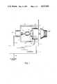
- FIG. 1is a plan view of the tactile feedback apparatus of the present invention
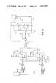
- FIG. 2is a schematic diagram of the control circuit for the tactile feedback apparatus of FIG. 1;
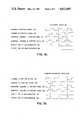
- FIG. 3ais a timing diagram for clockwise rotation of the encoder input shaft of the tactile feedback apparatus of FIG. 1;
- FIG. 3bis a timing diagram for counter-clockwise rotation of the encoder input shaft of the tactile feedback apparatus of FIG. 1.
- a handwheel 1is mounted on one end of a handwheel shaft 2.
- the handwheel shaftextends through the stationary coil 3 of an electromagnetic brake assembly shown in dashed line 4.
- the electromagnetic brake assembly 4is a commercially available device such as Model No. BF-20 available from Deltran, a division of American Precision.
- the rotor 5 of the electromagnetic brake 4is fixed onto the handwheel shaft 2.
- a flexible coupling 6 on the other end of the handwheel shaft 2connects the handwheel shaft 2 to the input shaft 7 of an incremental encoder 8.
- the encoder 8is a commercially available device such as Model No. HEDS-7500 available from Hewlett-Packard and it is supported and held in a fixed position by structural members 9 attached to a front panel 10.
- a control circuit 11connects to the encoder 8 via an encoder cable 12, to the stationary coil 3 of the electromagnetic brake 4 via a brake cable 13, and to an external device (not shown) via an external cable 14.
- the external deviceis some type of machine controller such as, for example, a Numerical Controller (NC) for which the handwheel 1 is to be used.
- NCNumerical Controller
- the tactile feedback apparatus for rotary manual input of the present inventionprovides the operator with tactile feedback similar to that of a mechanical detent action without the disadvantages of such a mechanism.
- the control circuit 11keeps the electromagnetic brake 4 normally energized. In the energized state, the brake 4 generates a torque of approximately 10 inch-ounces, which is easily overcome by manual rotation of the handwheel 1 and provides for a smooth slipping motion.
- the encoder 8As the handwheel 1 is turned, the encoder 8 generates incremental position signals 15a and 15b.
- the control circuit 11monitors the incremental position signals 15a and 15b and de-energizes the brake 4 for approximately 10 milliseconds every time the incremental position signal 15a completes an electrical cycle. This momentary loss of friction is felt by the operator thus providing the requisite tactile feedback.
- the encoder cable 12carries encoder position signals 15a and 15b for channel A 15a and channel B 15b, respectively.
- the position signals 15a and 15bare logic levels which are 90 degrees out of phase with respect to each other (i.e. in quadrature). These position signals 15a and 15b are applied to Schmitt triggered inverters 17a and 17b, respectively, which buffers and shapes the position signals 15a and 15b.
- the inverted position signals 18a and 18bare available for connection to the external device (not shown) and are connected to a pair of one shot multivibrators 19a and 19b. Because of the quadrature relationship of the inverted position signals 18a and 18b, the external device is able to ascertain in well known fashion both the direction of movement and the number of incremental positions moved.
- the one shot multivibrators 19a and 19bdecode the inverted position signals 18a and 18b to generate a pulse for each incremental position of movement in either direction.
- the inverted channel B position signal 18bis applied to the inverted clear (CLR) inputs 21a and 21b of both multivibrators 19a and 19b.
- the inverted channel A position signal 18ais applied to the negative edge clock input 22 of multivibrator 19a and to the positive edge clock input 23 of multivibrator 19b.
- the multivibrators 19a and 19bare enabled only when the channel B position signal 15b is low (inverted channel B position signal 18b high). Then, multivibrators 19a and 19b respond to the negative edge and positive edges for clockwise and counterclockwise motion respectively, of the inverted channel A position signal 18a.
- the inverted channel A position signal 18agoes from high to low while channel B position signal 15b is low, and multivibrator 19a is triggered.
- the inverted channel A position signal 18agoes from low to high while the channel B position signal 15b is low, and one shot multivibrator 19b is triggered.
- resistors 24a and 24b and capacitors 25a and 25bare timing elements for the multivibrators 19a and 19b, respectively, with values selected to yield a pulse of 10 milliseconds.
- the outputs 26a and 26b of the two multivibrators 19a and 19b, respectively,are combined in "or” gate 27, thus insuring a pulse at the same point in an incremental period and in either direction.
- the output 28 of "or" gate 27is applied to a drive circuit, shown in dashed line 29, for the electromagnetic brake 4.
- the drive circuit 29includes an inverter 30 to keep the brake 4 normally energized and a coil driving amplifier made up of resistors 31, transistors 32, and diodes 33 connected in well known fashion.
- the drive circuit output 34 together with a ground connection 35are connected to the stationary coil 3 through the brake cable 13.
- the tactile feedback apparatus of the present inventioncould easily be adapted for use with a wide variety of position transducers other than the incremental encoder 8 described in this embodiment.
- an absolute encoder(not shown) (i.e. one that indicates absolute position rather than relative incremental position) could be used with modification to the control circuit 11 to detect a change in the least significant bit of the absolute position to pulse the brake 4 off.
- other types of position transducerscould be used with attendant adaptations of the control circuit 11.
Landscapes
- Engineering & Computer Science (AREA)
- Human Computer Interaction (AREA)
- Manufacturing & Machinery (AREA)
- Physics & Mathematics (AREA)
- General Physics & Mathematics (AREA)
- Automation & Control Theory (AREA)
- Manipulator (AREA)
Abstract
Description
The field of the invention is rotary manual input mechanisms and more particularly, tactile feedback apparatuses used thereon.
There are numerous applications where a knob or crank is manually turned to carry out a control function. In a numerically controlled machine tool, for example, a handwheel may be provided on the control panel to enable the operator to manually "jog" the cutting tool along one or more axes of motion. The amount of handwheel rotation is translated into a digital quantity by a position transducer and is then employed to drive the appropriate servomechanism the desired distance. In such applications, it is essential to provide tactile feedback to the operator so that each time an incremental movement is made, the operator can feel it on the handwheel. The prevailing practice in prior control systems is to employ a detent mechanism to provide the needed tactile feedback. Each detent then corresponds to one incremental movement, for example 0.001 inch of jog, and the operator can feel a click from the detent for each such incremental movement. While detent mechanisms are generally satisfactory, they are mechanically complex and are subject to wear, requiring maintenance for lubrication and adjustment.
To eliminate the need for mechanical detents, other methods of providing tactile feedback have been developed. For example, a stepping motor can be used as the position transducer as described in U.S. Pat. No. 4,553,080 by the assignee of the present invention, wherein the static torque of the stepping motor provides tactile feedback. This approach too is satisfactory, but requires additional components to overcome a basic limitation, which is the possibility of missing pulses when the stepping motor is rotated too slowly. Also, a somewhat complex control circuit is required to convert the signals from the stepping motor into a form suitable for use by an external device.
The pulse generator of the present invention eliminates the need for a mechanical detent mechanism by instead utilizing a small electromagnetic brake and control circuit to provide the requisite operator feel. A handwheel shaft with a handwheel on one end is connected to the rotor of the electromagnetic brake. When the electromagnetic brake is energized, as is normally the case, a limited resistance to shaft rotation is provided which is small enough to be overcome by manual rotation of the handwheel. The other end of the handwheel shaft is coupled to the input shaft of a position transducer. The transducer generates signals indicative of the incremental position and direction of the transducer input shaft rotation. An electromagnetic brake driving circuit keeps the brake normally energized and monitors the transducer signals. When the transducer signals indicate that the shaft has been rotated one incremental position, the driving circuit momentarily de-energizes the electromagnetic brake thus providing tactile feedback to the operator similar to that of a mechanical detent.
A general object of the invention is to provide a tactile feedback apparatus which is mechanically simple, reliable, and which does not require periodic maintenance.
The foregoing and other objects and advantages of the invention will appear from the following description. In the description reference is made to the accompanying drawings which form a part hereof and in which there is shown a preferred embodiment of the invention. Such embodiment does not necessarily represent the full scope of the invention, however, and reference is made to the claims herein for interpreting the breadth of the invention.
FIG. 1 is a plan view of the tactile feedback apparatus of the present invention;
FIG. 2 is a schematic diagram of the control circuit for the tactile feedback apparatus of FIG. 1;
FIG. 3a is a timing diagram for clockwise rotation of the encoder input shaft of the tactile feedback apparatus of FIG. 1; and
FIG. 3b is a timing diagram for counter-clockwise rotation of the encoder input shaft of the tactile feedback apparatus of FIG. 1.
Referring to FIG. 1, ahandwheel 1 is mounted on one end of a handwheel shaft 2. The handwheel shaft extends through the stationary coil 3 of an electromagnetic brake assembly shown indashed line 4. Theelectromagnetic brake assembly 4 is a commercially available device such as Model No. BF-20 available from Deltran, a division of American Precision. The rotor 5 of theelectromagnetic brake 4 is fixed onto the handwheel shaft 2. A flexible coupling 6 on the other end of the handwheel shaft 2 connects the handwheel shaft 2 to the input shaft 7 of anincremental encoder 8. Theencoder 8 is a commercially available device such as Model No. HEDS-7500 available from Hewlett-Packard and it is supported and held in a fixed position by structural members 9 attached to afront panel 10.
A control circuit 11 connects to theencoder 8 via anencoder cable 12, to the stationary coil 3 of theelectromagnetic brake 4 via abrake cable 13, and to an external device (not shown) via anexternal cable 14. The external device (not shown) is some type of machine controller such as, for example, a Numerical Controller (NC) for which thehandwheel 1 is to be used.
The tactile feedback apparatus for rotary manual input of the present invention provides the operator with tactile feedback similar to that of a mechanical detent action without the disadvantages of such a mechanism. The control circuit 11 keeps theelectromagnetic brake 4 normally energized. In the energized state, thebrake 4 generates a torque of approximately 10 inch-ounces, which is easily overcome by manual rotation of thehandwheel 1 and provides for a smooth slipping motion.
Referring to FIGS. 1, 3a and 3b, as thehandwheel 1 is turned, theencoder 8 generatesincremental position signals brake 4 for approximately 10 milliseconds every time theincremental position signal 15a completes an electrical cycle. This momentary loss of friction is felt by the operator thus providing the requisite tactile feedback.
Referring now to FIG. 2, theencoder cable 12 carriesencoder position signals channel A 15a andchannel B 15b, respectively. The position signals 15a and 15b are logic levels which are 90 degrees out of phase with respect to each other (i.e. in quadrature). These position signals 15a and 15b are applied to Schmitt triggeredinverters 17a and 17b, respectively, which buffers and shapes the position signals 15a and 15b. After theinverters 17a and 17b, the inverted position signals 18a and 18b are available for connection to the external device (not shown) and are connected to a pair of oneshot multivibrators 19a and 19b. Because of the quadrature relationship of the inverted position signals 18a and 18b, the external device is able to ascertain in well known fashion both the direction of movement and the number of incremental positions moved.
The oneshot multivibrators 19a and 19b decode the inverted position signals 18a and 18b to generate a pulse for each incremental position of movement in either direction. The inverted channelB position signal 18b is applied to the inverted clear (CLR)inputs multivibrators 19a and 19b. The inverted channel Aposition signal 18a is applied to the negativeedge clock input 22 of multivibrator 19a and to the positiveedge clock input 23 ofmultivibrator 19b. Thus, themultivibrators 19a and 19b are enabled only when the channelB position signal 15b is low (inverted channelB position signal 18b high). Then,multivibrators 19a and 19b respond to the negative edge and positive edges for clockwise and counterclockwise motion respectively, of the inverted channelA position signal 18a.
Referring primarily to FIG. 3a, for clockwise rotation the inverted channel Aposition signal 18a goes from high to low while channelB position signal 15b is low, and multivibrator 19a is triggered. Similarly, referring to FIG. 3b, for counterclockwise rotation the inverted channel Aposition signal 18a goes from low to high while the channelB position signal 15b is low, and oneshot multivibrator 19b is triggered.
Referring back now to FIG. 2,resistors capacitors 25a and 25b are timing elements for themultivibrators 19a and 19b, respectively, with values selected to yield a pulse of 10 milliseconds. Theoutputs 26a and 26b of the twomultivibrators 19a and 19b, respectively, are combined in "or" gate 27, thus insuring a pulse at the same point in an incremental period and in either direction. Theoutput 28 of "or" gate 27 is applied to a drive circuit, shown in dashed line 29, for theelectromagnetic brake 4. The drive circuit 29 includes an inverter 30 to keep thebrake 4 normally energized and a coil driving amplifier made up ofresistors 31,transistors 32, anddiodes 33 connected in well known fashion. The drive circuit output 34 together with a ground connection 35 are connected to the stationary coil 3 through thebrake cable 13.
It should be apparent to one skilled in the art that the tactile feedback apparatus of the present invention could easily be adapted for use with a wide variety of position transducers other than theincremental encoder 8 described in this embodiment. For example, an absolute encoder (not shown) (i.e. one that indicates absolute position rather than relative incremental position) could be used with modification to the control circuit 11 to detect a change in the least significant bit of the absolute position to pulse thebrake 4 off. Similarly, other types of position transducers could be used with attendant adaptations of the control circuit 11.
Claims (5)
1. A tactile feedback apparatus for rotary manual input which comprises:
a handwheel rigidly mounted on a rotatably supported handwheel shaft;
an electromechanical brake attached to the handwheel shaft and being operable when energized to urge a pair of frictional surfaces together to provide a limited resistance to shaft rotation, said resistance being small enough to be overcome by manual rotation of the handwheel;
a position transducer mounted in a fixed position and having an input shaft coupled to the handwheel shaft, said transducer being operable to generate position signals indicative of the incremental rotation of the transducer input shaft; and
a control circuit coupled to receive the transducer position signals and produce a drive signal to the electromagnetic brake, said control circuit including:
a detector circuit coupled to receive the transducer position signals and being operable to produce an output signal each time the transducer input shaft is rotated one increment; and
an electromagnetic brake dirving circuit coupled to receive the detector circuit output signald and being operable to produce the drive signal which keeps the electromagnetic brake normally energized and momentarily de-energizes the electromagnetic brake for each occurrence of the detector circuit output signal.
2. The tactile feedback apparatus as recited in claim 1 in which the position transducer is an incremental encoder.
3. The tactile feedback apparatus as recited in claim 2 in which position signals from the incremental encoder include two logic signals in quadrature.
4. The tactile feedback apparatus as recited in claim 1 in which the duration of the detector output signal is approximately 10 milliseconds.
5. The tactile feedback apparatus as recited in claim 1 in which the detector circuit includes at least one astable multivibrator device.
Priority Applications (1)
| Application Number | Priority Date | Filing Date | Title |
|---|---|---|---|
| US06/794,432US4652805A (en) | 1985-11-04 | 1985-11-04 | Tactile feedback apparatus for rotary manual input |
Applications Claiming Priority (1)
| Application Number | Priority Date | Filing Date | Title |
|---|---|---|---|
| US06/794,432US4652805A (en) | 1985-11-04 | 1985-11-04 | Tactile feedback apparatus for rotary manual input |
Publications (1)
| Publication Number | Publication Date |
|---|---|
| US4652805Atrue US4652805A (en) | 1987-03-24 |
Family
ID=25162609
Family Applications (1)
| Application Number | Title | Priority Date | Filing Date |
|---|---|---|---|
| US06/794,432Expired - LifetimeUS4652805A (en) | 1985-11-04 | 1985-11-04 | Tactile feedback apparatus for rotary manual input |
Country Status (1)
| Country | Link |
|---|---|
| US (1) | US4652805A (en) |
Cited By (33)
| Publication number | Priority date | Publication date | Assignee | Title |
|---|---|---|---|---|
| US4947097A (en)* | 1989-06-12 | 1990-08-07 | The Grass Valley Group, Inc. | Automatic switching of motion control with tactile feedback |
| US20010010513A1 (en)* | 1998-06-23 | 2001-08-02 | Immersion Corporation | Tactile mouse |
| US6373676B1 (en)* | 1998-10-05 | 2002-04-16 | Span Inc. | Magnetic floatation control system |
| US20020072814A1 (en)* | 1991-10-24 | 2002-06-13 | Immersion Corporation | Interface device with tactile responsiveness |
| US20030080939A1 (en)* | 2001-10-30 | 2003-05-01 | Alps Electric Co., Ltd. | Lever handle type haptic input apparatus equipped with electromagnetic brake |
| US20040040800A1 (en)* | 2002-07-31 | 2004-03-04 | George Anastas | System and method for providing passive haptic feedback |
| US6710518B2 (en)* | 2002-05-31 | 2004-03-23 | Motorola, Inc. | Manually operable electronic apparatus |
| EP1041473A3 (en)* | 1991-10-24 | 2004-12-29 | Immersion Corporation | Actuator having electronically controllable tactile responsiveness |
| US20050012710A1 (en)* | 2003-05-30 | 2005-01-20 | Vincent Hayward | System and method for low power haptic feedback |
| US20050275967A1 (en)* | 2004-05-27 | 2005-12-15 | Olien Neil T | Products and processes for providing haptic feedback in resistive interface devices |
| US20060021828A1 (en)* | 2004-07-29 | 2006-02-02 | Olien Neil T | Systems and methods for providing haptic feedback with position sensing |
| US20060033703A1 (en)* | 2004-08-11 | 2006-02-16 | Olien Neil T | Systems and methods for providing friction in a haptic feedback device |
| US20060038781A1 (en)* | 2004-08-20 | 2006-02-23 | Levin Michael D | Systems and methods for providing haptic effects |
| US20060044271A1 (en)* | 2004-08-24 | 2006-03-02 | Anastas George V | Magnetic actuator for providing haptic feedback |
| US20060049010A1 (en)* | 2004-09-03 | 2006-03-09 | Olien Neil T | Device and method for providing resistive and vibrotactile effects |
| US20060054427A1 (en)* | 2004-09-10 | 2006-03-16 | Alexander Jasso | Systems and methods for providing a haptic device |
| US20060061558A1 (en)* | 2004-09-20 | 2006-03-23 | Danny Grant | Products and processes for providing multimodal feedback in a user interface device |
| US20060071917A1 (en)* | 2004-09-24 | 2006-04-06 | Gomez Daniel H | Systems and methods for providing a haptic device |
| US20060117258A1 (en)* | 2004-11-30 | 2006-06-01 | Raymond Yu | User interface device |
| US20060159539A1 (en)* | 2005-01-19 | 2006-07-20 | The Boeing Company (De Corporation) | Automatic position-locking tool carrier apparatus and method |
| WO2007022961A1 (en)* | 2005-08-26 | 2007-03-01 | Olympus Soft Imaging Solutions Gmbh | Optical recording and/0r reading unit |
| US7249951B2 (en) | 1996-09-06 | 2007-07-31 | Immersion Corporation | Method and apparatus for providing an interface mechanism for a computer simulation |
| US20070279401A1 (en)* | 2006-06-02 | 2007-12-06 | Immersion Corporation | Hybrid haptic device |
| US20080055244A1 (en)* | 2003-12-30 | 2008-03-06 | Immersion Corporation | Control schemes for haptic feedback interface devices |
| US20090281664A1 (en)* | 2008-05-06 | 2009-11-12 | Hurco Companies, Inc. | Mouse-Based Hand Wheel Control For a Machine Tool |
| DE102008042186A1 (en)* | 2008-09-18 | 2010-03-25 | Koenig & Bauer Aktiengesellschaft | Manually operated speed sensor for use in printing press or in print finishing machine, has swiveling and manually movable sensor element, where direct current motor is arranged |
| US20100265191A1 (en)* | 2009-04-21 | 2010-10-21 | Motorola, Inc. | Methods and Devices for Consistency of the Haptic Response Across a Touch Sensitive Device |
| EP2495626A1 (en)* | 2011-03-01 | 2012-09-05 | G.D Societa' per Azioni | Method of controlling the electric drive of an automatic manufacturing machine, and automatic manufacturing machine with electric drive control |
| US8803796B2 (en) | 2004-08-26 | 2014-08-12 | Immersion Corporation | Products and processes for providing haptic feedback in a user interface |
| CN104750164A (en)* | 2013-12-25 | 2015-07-01 | 财团法人工业技术研究院 | Method and device for providing feedback force and processing machine system |
| US20160288701A1 (en)* | 2014-07-21 | 2016-10-06 | Kostal Of America | Turn signal systems and methods |
| EP3111143A1 (en)* | 2014-02-24 | 2017-01-04 | BSH Hausgeräte GmbH | Household appliance with a control device |
| US11347188B2 (en) | 2017-01-25 | 2022-05-31 | Microsoft Technology Licensing, Llc | Stepper motor for use in rotary control assembly of input device |
Citations (3)
| Publication number | Priority date | Publication date | Assignee | Title |
|---|---|---|---|---|
| GB2016225A (en)* | 1978-03-02 | 1979-09-19 | Ricoh Kk | Stepper motor control systems |
| US4515251A (en)* | 1983-01-26 | 1985-05-07 | Warner Electric Brake & Clutch Company | Electromagnetic brake with improved armature mounting |
| US4553080A (en)* | 1983-07-25 | 1985-11-12 | Allen-Bradley Company | Position transducer |
- 1985
- 1985-11-04USUS06/794,432patent/US4652805A/ennot_activeExpired - Lifetime
Patent Citations (3)
| Publication number | Priority date | Publication date | Assignee | Title |
|---|---|---|---|---|
| GB2016225A (en)* | 1978-03-02 | 1979-09-19 | Ricoh Kk | Stepper motor control systems |
| US4515251A (en)* | 1983-01-26 | 1985-05-07 | Warner Electric Brake & Clutch Company | Electromagnetic brake with improved armature mounting |
| US4553080A (en)* | 1983-07-25 | 1985-11-12 | Allen-Bradley Company | Position transducer |
Cited By (72)
| Publication number | Priority date | Publication date | Assignee | Title |
|---|---|---|---|---|
| DE4018686A1 (en)* | 1989-06-12 | 1990-12-13 | Grass Valley Group | AUTOMATIC SWITCHING OF THE MOTION CONTROL WITH FEELABLE FEEDBACK |
| US4947097A (en)* | 1989-06-12 | 1990-08-07 | The Grass Valley Group, Inc. | Automatic switching of motion control with tactile feedback |
| US7812820B2 (en) | 1991-10-24 | 2010-10-12 | Immersion Corporation | Interface device with tactile responsiveness |
| US20020072814A1 (en)* | 1991-10-24 | 2002-06-13 | Immersion Corporation | Interface device with tactile responsiveness |
| EP1041473A3 (en)* | 1991-10-24 | 2004-12-29 | Immersion Corporation | Actuator having electronically controllable tactile responsiveness |
| US7249951B2 (en) | 1996-09-06 | 2007-07-31 | Immersion Corporation | Method and apparatus for providing an interface mechanism for a computer simulation |
| US20010010513A1 (en)* | 1998-06-23 | 2001-08-02 | Immersion Corporation | Tactile mouse |
| US7136045B2 (en) | 1998-06-23 | 2006-11-14 | Immersion Corporation | Tactile mouse |
| US6373676B1 (en)* | 1998-10-05 | 2002-04-16 | Span Inc. | Magnetic floatation control system |
| US20030080939A1 (en)* | 2001-10-30 | 2003-05-01 | Alps Electric Co., Ltd. | Lever handle type haptic input apparatus equipped with electromagnetic brake |
| US7176892B2 (en)* | 2001-10-30 | 2007-02-13 | Alps Electric Co., Ltd. | Lever handle type haptic input apparatus equipped with electromagnetic brake |
| US6710518B2 (en)* | 2002-05-31 | 2004-03-23 | Motorola, Inc. | Manually operable electronic apparatus |
| US20080036735A1 (en)* | 2002-07-31 | 2008-02-14 | Immersion Corporation | System and Method for Providing Passive Haptic Feedback |
| US20080041671A1 (en)* | 2002-07-31 | 2008-02-21 | Immersion Corporation | System and Method for Providing Passive Haptic Feedback |
| US20080036736A1 (en)* | 2002-07-31 | 2008-02-14 | Immersion Corporation | System and Method for Providing Passive Haptic Feedback |
| US20080035435A1 (en)* | 2002-07-31 | 2008-02-14 | Immersion Corporation | System and Method for Providing Passive Haptic Feedback |
| US20040040800A1 (en)* | 2002-07-31 | 2004-03-04 | George Anastas | System and method for providing passive haptic feedback |
| US9274600B2 (en) | 2002-07-31 | 2016-03-01 | Immersion Corporation | System and method for providing passive haptic feedback |
| US8248363B2 (en) | 2002-07-31 | 2012-08-21 | Immersion Corporation | System and method for providing passive haptic feedback |
| US7567243B2 (en) | 2003-05-30 | 2009-07-28 | Immersion Corporation | System and method for low power haptic feedback |
| US8619031B2 (en) | 2003-05-30 | 2013-12-31 | Immersion Corporation | System and method for low power haptic feedback |
| US20090284498A1 (en)* | 2003-05-30 | 2009-11-19 | Immersion Corporation | System and method for low power haptic feedback |
| US20050012710A1 (en)* | 2003-05-30 | 2005-01-20 | Vincent Hayward | System and method for low power haptic feedback |
| US20080055244A1 (en)* | 2003-12-30 | 2008-03-06 | Immersion Corporation | Control schemes for haptic feedback interface devices |
| US8519948B2 (en) | 2003-12-30 | 2013-08-27 | Immersion Corporation | Control schemes for haptic feedback interface devices |
| US8519947B2 (en) | 2003-12-30 | 2013-08-27 | Immersion Corporation | Control schemes for haptic feedback interface devices |
| US20080073131A1 (en)* | 2003-12-30 | 2008-03-27 | Immersion Corporation, A Delaware Corporation | Control schemes for haptic feedback interface devices |
| US7522152B2 (en) | 2004-05-27 | 2009-04-21 | Immersion Corporation | Products and processes for providing haptic feedback in resistive interface devices |
| US20050275967A1 (en)* | 2004-05-27 | 2005-12-15 | Olien Neil T | Products and processes for providing haptic feedback in resistive interface devices |
| US8154512B2 (en) | 2004-05-27 | 2012-04-10 | Immersion Coporation | Products and processes for providing haptic feedback in resistive interface devices |
| US20090231113A1 (en)* | 2004-05-27 | 2009-09-17 | Olien Neil T | Products and Processes For Providing Haptic Feedback In Resistive Interface Devices |
| US20060021828A1 (en)* | 2004-07-29 | 2006-02-02 | Olien Neil T | Systems and methods for providing haptic feedback with position sensing |
| US7198137B2 (en) | 2004-07-29 | 2007-04-03 | Immersion Corporation | Systems and methods for providing haptic feedback with position sensing |
| US20060033703A1 (en)* | 2004-08-11 | 2006-02-16 | Olien Neil T | Systems and methods for providing friction in a haptic feedback device |
| US8441433B2 (en) | 2004-08-11 | 2013-05-14 | Immersion Corporation | Systems and methods for providing friction in a haptic feedback device |
| US20060038781A1 (en)* | 2004-08-20 | 2006-02-23 | Levin Michael D | Systems and methods for providing haptic effects |
| US9495009B2 (en) | 2004-08-20 | 2016-11-15 | Immersion Corporation | Systems and methods for providing haptic effects |
| US10179540B2 (en) | 2004-08-20 | 2019-01-15 | Immersion Corporation | Systems and methods for providing haptic effects |
| US20060044271A1 (en)* | 2004-08-24 | 2006-03-02 | Anastas George V | Magnetic actuator for providing haptic feedback |
| US8013847B2 (en)* | 2004-08-24 | 2011-09-06 | Immersion Corporation | Magnetic actuator for providing haptic feedback |
| US8803796B2 (en) | 2004-08-26 | 2014-08-12 | Immersion Corporation | Products and processes for providing haptic feedback in a user interface |
| US20060049010A1 (en)* | 2004-09-03 | 2006-03-09 | Olien Neil T | Device and method for providing resistive and vibrotactile effects |
| US20080024440A1 (en)* | 2004-09-03 | 2008-01-31 | Immersion Corporation | Device and Method for Providing Resistive and Vibrotactile Effects |
| US8002089B2 (en) | 2004-09-10 | 2011-08-23 | Immersion Corporation | Systems and methods for providing a haptic device |
| US20060054427A1 (en)* | 2004-09-10 | 2006-03-16 | Alexander Jasso | Systems and methods for providing a haptic device |
| US9046922B2 (en) | 2004-09-20 | 2015-06-02 | Immersion Corporation | Products and processes for providing multimodal feedback in a user interface device |
| US20060061558A1 (en)* | 2004-09-20 | 2006-03-23 | Danny Grant | Products and processes for providing multimodal feedback in a user interface device |
| US20060071917A1 (en)* | 2004-09-24 | 2006-04-06 | Gomez Daniel H | Systems and methods for providing a haptic device |
| US8018434B2 (en) | 2004-09-24 | 2011-09-13 | Immersion Corporation | Systems and methods for providing a haptic device |
| US7764268B2 (en) | 2004-09-24 | 2010-07-27 | Immersion Corporation | Systems and methods for providing a haptic device |
| US20100283588A1 (en)* | 2004-09-24 | 2010-11-11 | Immersion Corporation | Systems And Methods For Providing A Haptic Device |
| US20060117258A1 (en)* | 2004-11-30 | 2006-06-01 | Raymond Yu | User interface device |
| US7456821B2 (en) | 2004-11-30 | 2008-11-25 | Immersion Corporation | User interface device |
| US20060159539A1 (en)* | 2005-01-19 | 2006-07-20 | The Boeing Company (De Corporation) | Automatic position-locking tool carrier apparatus and method |
| US7112018B2 (en) | 2005-01-19 | 2006-09-26 | The Boeing Company | Automatic position-locking tool carrier apparatus and method |
| US20090244697A1 (en)* | 2005-08-26 | 2009-10-01 | Tuempner Juergen | Optical recording and/or reproduction unit |
| WO2007022961A1 (en)* | 2005-08-26 | 2007-03-01 | Olympus Soft Imaging Solutions Gmbh | Optical recording and/0r reading unit |
| US20070279401A1 (en)* | 2006-06-02 | 2007-12-06 | Immersion Corporation | Hybrid haptic device |
| US8174512B2 (en) | 2006-06-02 | 2012-05-08 | Immersion Corporation | Hybrid haptic device utilizing mechanical and programmable haptic effects |
| WO2009137357A1 (en)* | 2008-05-06 | 2009-11-12 | Hurco Companies, Inc. | Mouse-based hand wheel control for a machine tool |
| US8041448B2 (en) | 2008-05-06 | 2011-10-18 | Hurco Companies, Inc. | Mouse-based hand wheel control for a machine tool |
| US20090281664A1 (en)* | 2008-05-06 | 2009-11-12 | Hurco Companies, Inc. | Mouse-Based Hand Wheel Control For a Machine Tool |
| DE102008042186A1 (en)* | 2008-09-18 | 2010-03-25 | Koenig & Bauer Aktiengesellschaft | Manually operated speed sensor for use in printing press or in print finishing machine, has swiveling and manually movable sensor element, where direct current motor is arranged |
| US9164584B2 (en) | 2009-04-21 | 2015-10-20 | Google Technology Holdings LLC | Methods and devices for consistency of the haptic response across a touch sensitive device |
| US20100265191A1 (en)* | 2009-04-21 | 2010-10-21 | Motorola, Inc. | Methods and Devices for Consistency of the Haptic Response Across a Touch Sensitive Device |
| EP2495626A1 (en)* | 2011-03-01 | 2012-09-05 | G.D Societa' per Azioni | Method of controlling the electric drive of an automatic manufacturing machine, and automatic manufacturing machine with electric drive control |
| CN104750164A (en)* | 2013-12-25 | 2015-07-01 | 财团法人工业技术研究院 | Method and device for providing feedback force and processing machine system |
| US10241495B2 (en) | 2013-12-25 | 2019-03-26 | Industrial Technology Research Institute | Apparatus and method for providing feedback force and machine tool system |
| EP3111143A1 (en)* | 2014-02-24 | 2017-01-04 | BSH Hausgeräte GmbH | Household appliance with a control device |
| US20160288701A1 (en)* | 2014-07-21 | 2016-10-06 | Kostal Of America | Turn signal systems and methods |
| US9834137B2 (en)* | 2014-07-21 | 2017-12-05 | Kostal Of America | Turn signal systems and methods |
| US11347188B2 (en) | 2017-01-25 | 2022-05-31 | Microsoft Technology Licensing, Llc | Stepper motor for use in rotary control assembly of input device |
Similar Documents
| Publication | Publication Date | Title |
|---|---|---|
| US4652805A (en) | Tactile feedback apparatus for rotary manual input | |
| US4553080A (en) | Position transducer | |
| US4639653A (en) | Method and apparatus for performing work in a three dimensional space | |
| EP0134017B1 (en) | Microprocessor - controlled positioning system | |
| MX9207613A (en) | INTERACTIVE ROTARY CONTROLLER SYSTEM WITH TOUCH FEEDBACK. | |
| JPS59188518A (en) | Detection system for absolute position of servocontrol system | |
| US3267344A (en) | Numerically controlled work and feed motor driven gear-hobber | |
| JP2568068B2 (en) | Motor rotor position detector | |
| US3497778A (en) | Part positioning device and plural stepping motor control therefor | |
| US4221998A (en) | High accuracy control system | |
| EP0201106A2 (en) | Absolute Position encoder | |
| US4346334A (en) | DC Servomotor system | |
| US4724371A (en) | Apparatus for detecting the degree of rotation of a rotational axis | |
| US4282955A (en) | Rotary shaft control system | |
| JP2807710B2 (en) | Digital servo controller | |
| JP2907164B2 (en) | Numerical control unit | |
| JP3528949B2 (en) | Absolute position detection device for output rotary shaft | |
| EP0237511B1 (en) | Arrangement of a hand wheel on a sewing machine | |
| CA1323699C (en) | Method of detecting a position of a robot | |
| JP2819411B2 (en) | Fixed position stop control device | |
| US2907222A (en) | Servo system having precision reversiblity | |
| JPS62152016A (en) | industrial robot | |
| JP2528540B2 (en) | Command signal generation method | |
| JPH0123268B2 (en) | ||
| JPS61209313A (en) | Robot joint angle detection device |
Legal Events
| Date | Code | Title | Description |
|---|---|---|---|
| AS | Assignment | Owner name:ALLEN-BRADLEY COMPANY, MILWAUKEE, WISCONSIN, A COR Free format text:ASSIGNMENT OF ASSIGNORS INTEREST.;ASSIGNOR:KOHN, GABRIEL S.;REEL/FRAME:004479/0464 Effective date:19851016 | |
| STCF | Information on status: patent grant | Free format text:PATENTED CASE | |
| AS | Assignment | Owner name:ALLEN-BRADLEY COMPANY Free format text:MERGER;ASSIGNORS:ALLEN-BRADLEY COMPANY (MERGED INTO);NEW A-B CO., INC., (CHANGED TO);REEL/FRAME:005165/0612 Effective date:19851231 | |
| FEPP | Fee payment procedure | Free format text:PAYOR NUMBER ASSIGNED (ORIGINAL EVENT CODE: ASPN); ENTITY STATUS OF PATENT OWNER: LARGE ENTITY | |
| FPAY | Fee payment | Year of fee payment:4 | |
| FPAY | Fee payment | Year of fee payment:8 | |
| FPAY | Fee payment | Year of fee payment:12 |