US4652260A - Infusion device - Google Patents
Infusion deviceDownload PDFInfo
- Publication number
- US4652260A US4652260AUS06/710,009US71000985AUS4652260AUS 4652260 AUS4652260 AUS 4652260AUS 71000985 AUS71000985 AUS 71000985AUS 4652260 AUS4652260 AUS 4652260A
- Authority
- US
- United States
- Prior art keywords
- syringe
- infusion device
- coupling
- pulses
- connector
- Prior art date
- Legal status (The legal status is an assumption and is not a legal conclusion. Google has not performed a legal analysis and makes no representation as to the accuracy of the status listed.)
- Expired - Fee Related
Links
- 238000001802infusionMethods0.000titleclaimsabstractdescription57
- 230000008878couplingEffects0.000claimsdescription32
- 238000010168coupling processMethods0.000claimsdescription32
- 238000005859coupling reactionMethods0.000claimsdescription32
- 230000033001locomotionEffects0.000claimsdescription22
- 239000012530fluidSubstances0.000claimsdescription12
- 241000269627Amphiuma meansSpecies0.000claimsdescription5
- 230000002452interceptive effectEffects0.000claimsdescription4
- 230000003287optical effectEffects0.000claimsdescription4
- 230000000295complement effectEffects0.000claimsdescription2
- 238000001579optical reflectometryMethods0.000claimsdescription2
- 238000011144upstream manufacturingMethods0.000claims2
- 238000010586diagramMethods0.000description4
- 239000000463materialSubstances0.000description3
- 239000004698PolyethyleneSubstances0.000description1
- 230000001419dependent effectEffects0.000description1
- 238000001514detection methodMethods0.000description1
- 238000001990intravenous administrationMethods0.000description1
- 239000002184metalSubstances0.000description1
- 229920003023plasticPolymers0.000description1
- 239000004033plasticSubstances0.000description1
- -1polyethylenePolymers0.000description1
- 229920000573polyethylenePolymers0.000description1
- 239000004800polyvinyl chlorideSubstances0.000description1
- 229920000915polyvinyl chloridePolymers0.000description1
- 230000000284resting effectEffects0.000description1
Images


Classifications
- A—HUMAN NECESSITIES
- A61—MEDICAL OR VETERINARY SCIENCE; HYGIENE
- A61M—DEVICES FOR INTRODUCING MEDIA INTO, OR ONTO, THE BODY; DEVICES FOR TRANSDUCING BODY MEDIA OR FOR TAKING MEDIA FROM THE BODY; DEVICES FOR PRODUCING OR ENDING SLEEP OR STUPOR
- A61M5/00—Devices for bringing media into the body in a subcutaneous, intra-vascular or intramuscular way; Accessories therefor, e.g. filling or cleaning devices, arm-rests
- A61M5/14—Infusion devices, e.g. infusing by gravity; Blood infusion; Accessories therefor
- A61M5/142—Pressure infusion, e.g. using pumps
- A61M5/145—Pressure infusion, e.g. using pumps using pressurised reservoirs, e.g. pressurised by means of pistons
- A61M5/1452—Pressure infusion, e.g. using pumps using pressurised reservoirs, e.g. pressurised by means of pistons pressurised by means of pistons
- A61M5/1456—Pressure infusion, e.g. using pumps using pressurised reservoirs, e.g. pressurised by means of pistons pressurised by means of pistons with a replaceable reservoir comprising a piston rod to be moved into the reservoir, e.g. the piston rod is part of the removable reservoir
- A—HUMAN NECESSITIES
- A61—MEDICAL OR VETERINARY SCIENCE; HYGIENE
- A61M—DEVICES FOR INTRODUCING MEDIA INTO, OR ONTO, THE BODY; DEVICES FOR TRANSDUCING BODY MEDIA OR FOR TAKING MEDIA FROM THE BODY; DEVICES FOR PRODUCING OR ENDING SLEEP OR STUPOR
- A61M5/00—Devices for bringing media into the body in a subcutaneous, intra-vascular or intramuscular way; Accessories therefor, e.g. filling or cleaning devices, arm-rests
- A61M5/14—Infusion devices, e.g. infusing by gravity; Blood infusion; Accessories therefor
- A61M5/168—Means for controlling media flow to the body or for metering media to the body, e.g. drip meters, counters ; Monitoring media flow to the body
- A61M5/172—Means for controlling media flow to the body or for metering media to the body, e.g. drip meters, counters ; Monitoring media flow to the body electrical or electronic
- Y—GENERAL TAGGING OF NEW TECHNOLOGICAL DEVELOPMENTS; GENERAL TAGGING OF CROSS-SECTIONAL TECHNOLOGIES SPANNING OVER SEVERAL SECTIONS OF THE IPC; TECHNICAL SUBJECTS COVERED BY FORMER USPC CROSS-REFERENCE ART COLLECTIONS [XRACs] AND DIGESTS
- Y10—TECHNICAL SUBJECTS COVERED BY FORMER USPC
- Y10S—TECHNICAL SUBJECTS COVERED BY FORMER USPC CROSS-REFERENCE ART COLLECTIONS [XRACs] AND DIGESTS
- Y10S128/00—Surgery
- Y10S128/12—Pressure infusion
Definitions
- This inventionrelates to devices for driving a fluid-dispensing syringe and, more particularly, to motor driven devices used in conjunction with tubing sets having specially configured connectors.
- An infusion deviceis generally used to control the automatic dispensing of fluids from a syringe, for example, to a capillary tube which in turn might introduce those fluids to a patient. In many cases, it is extremely important that the rate of fluid delivery be correctly selected and accurately controlled.
- infusion devicesIn the prior art, several types of infusion devices have been used.
- One type of deviceincorporates a housing for supporting a syringe and utilizes an electrical motor, and associated drive circuitry configured to drive the plunger of the syringe at a constant rate.
- an electrical motorand associated drive circuitry configured to drive the plunger of the syringe at a constant rate.
- a lead screw coupling between the electric motor and the plungerincorporates a lead screw coupling between the electric motor and the plunger.
- direct gear couplershave been used.
- Stepper motorshave also been used, but the power requirements for stepper motors have been greater than is desirable for a light, compact device.
- infusion devicesthat can accomodate different size syringes and that can provide different drive rates for the respective syringes in an automatic manner that is not dependent on operator selection. It is furthermore desirable to provide tubing sets for infusion devices that make the use of the devices more convenient. It is an object of the present invention to provide an improved infusion device with these characteristics.
- Another objectis to provide such an infusion device that operates automatically and reliably without excessive controls or control devices, that accommodates different size syringes, and that varies the drive rate for the syringe plunger according to the size of the syringe.
- Another objectis to provide an infusion device that will cooperate with a specially configured tubing set connector for control of the operation of the infusion device.
- Still another objectis to provide a tubing set connector for rapid and reliable and sterile connection to an infusion device. Another object is to provide such a connector that will cooperate with an infusion device in determining the position of syringes in the infusion device and in controlling the speed of operation of a syringe plunger in the device accordingly.
- a stepper motorhaving an output shaft, the motor being responsive to an applied pulse to rotate the shaft a predeterined angular increment in a first direction
- coupling meansfor coupling the output shaft to the driver member whereby the driver member translates a predetermined linear increment along the reference axis in response to each of the incremental rotations of the shaft
- control meansincluding a battery power supply and an associated electrical circuit means operative in a pump mode for generating a succession of pulses, and for applying the succession of pulses to the motor, the circuit means being characterized by relatively high current drain from the power supply during the pulses and relatively low current drain from the power supply between the pulses.
- the deviceincludes a ratchet assembly coupled to the stepper motor, the ratchet assembly including means for permitting incremental rotational motion of the shaft in the first direction and for preventing rotational motions of the shaft having amplitude equal to or greater than the predetermined angular increment in the other direction, and the ratchet assembly includes a saw-toothed rimmed disk member affixed to the armature and a ring element affixed to the stator, the ring element including a pawl extending inward thereof and in interfering engagement with the saw-tooth rim.
- the coupling means of a preferred embodimentincludes a first roller and second roller, an endless belt disposed about the first and second rollers, motor coupling means for coupling rotory motion of the output shaft to the first roller, whereby the first roller rotates a predetermined angular increment and the belt translates a predetermined linear increment in response to each incremental rotation of the shaft, and drive coupling means for selectively coupling the belt to the driver member.
- the driver coupling meanspreferably includes a selectively operable clutch assembly, the clutch assembly being operative to decouple the driver means from the belt in response to an operator applied force, said clutch assembly being inoperative otherwise.
- the belt in the preferred embodimenthas a ridged inner surface, the ridges extending transverse to the direction of the belt, and the clutch assembly includes a platen member overlying in a fixed relationship to the outer surface of the belt and includes a ridged clutch member wherein the ridges of the clutch member are complementary to the ridges of the belt, wherein the ridged clutch member is positionable in a first position with the clutch member ridges engaging the ridges of the belt, and positionable in a second position with the clutch member disengaged from the belt.
- the inventionalso includes, in an infusion device including a sensor for generating a force signal representative applied thereto in the direction of the reference axis, control means including circuitry responsive to the force signal for generating an occlusion alarm signal when the force signal is representative of a force above a predetermined threshold value.
- the infusion deviceincludes an elongated flexible tube defining a central bore therethrough, and a rigid connector member affixed to the tube and defining a linear central bore extending therethrough, the bores defining a continuous passageway, extending from an input port of said connector member, and the connector member and including means for coupling the input port to the outlet port of said syringe, and the connector member includes at least two support portions spaced apart along the axis of the connector member central bore and an interface portion connecting the support portions, and the outer surfaces of the support portions are substantially identical in shape, the shape being adapted to interfit with the support member, whereby either of the support portions may be supported by the support member, wherein the connector member includes at least two actuating means for selective interfering engagement with the sensor.
- the actuating meansincludes at least two actuating surfaces for abutting engagement with the sensor, and the actuating surfaces are spaced apart along the axis of the connector member central bore.
- the infusion deviceincludes size means for generating a syringe size signal representative of the size of a syringe
- the control meansincludes circuitry responsive to the syringe size signal, to control the pulse repetition rate of the succession of pulses in a predetermined manner
- the size meansincluding means for sensing the position of the fluid dispensing outlet port of the syringe and further comprising an elongated flexible tube defining a central bore therethrough, and a rigid connector member affixed to the tube and defining a linear central bore extending therethrough, the bores defining a continuous passageway, extending from an input port of the connector member, and the connector member and including means for coupling the input port to the outlet port of the syringe
- the connector memberincludes at least two support portions spaced apart along the axis of the connector member central bore and an interface portion connecting the support portions, and wherein the outer surfaces of the support portions are substantially identical in shape, the shape being adapted to interfit with the
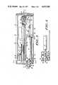
- FIG. 1shows a perspective view of an exemplary embodiment of an infusion device in accordance with the invention
- FIG. 2is a view like that of FIG. 1 with a hinged door of the device open to show the syringe compartment of the device;
- FIG. 3is a plan view of the infusion device with the top cover removed in which one size syringe is located in the syringe compartment;
- FIG. 4is a partial plan view like FIG. 3 showing a different size syringe in the syringe compartment;
- FIG. 5is a sectional side view of the device along the line 5--5 of FIG. 3;
- FIG. 6is an exploded view of the slide and the plunger driver of the infusion device
- FIGS. 7 and 8are views showing the relationship of the slide, plunger driver, and drive belt for engagement of the drive belt
- FIG. 9is a sectional view of the inside front of the device along the line 9--9 of FIG. 3;
- FIG. 10is a sectional view of the front of the device along the line 10--10 of FIG. 9;
- FIG. 11is a perspective view of the connector
- FIG. 12is a sectional view of the connector
- FIG. 13is an exploded view of the ratchet assembly for the stepper motor of the infusion device
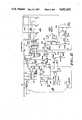
- FIG. 14is a schematic diagram of the control circuit for the device for bipolar operation.
- FIG. 15is a schematic diagram for an alternate, unipolar, operation.
- the infusion device 10 embodying the inventionincludes an elongate housing 12 having a base member 14 and a hinged door 18 that may be opened to insert a syringe 20 and tubing set 22 in a syringe compartment 24 of the device 10.
- the door 18 and the cover 16are appropriately molded so that the door 18 can be snapped shut for operation of the device 10 after a syringe 20 is placed into it.
- the housing 12also includes a front, or toe, portion 26 that defines an open topped slot 28 when the door 18 is open.
- the slot 28allows communication between the flexible tubing 30 of the tubing set 22 and the syringe 20 in the syringe compartment 24.
- the syringe compartment 24extends along the length of one side of the device 10. Located in the syringe compartment 24 is a movable plunger driver 32 for engagement and movement of the plunger 34 of a syringe 20 placed in the compartment 24.
- the plunger driver 32has a generally planar vertical end portion 36 perpendicular to the axis 37 of the syringe compartment 24, including a saucer shaped shallow recess 38 in which the end 40 of a plunger 34 may be seated.
- Another portion of the plunger driver 32is a vertical plate 42 that extends parallel to the compartment axis 37 along a dividing wall 44 separating the syringe compartment 24 from the drive assembly compartment 46.
- the dividing wall 44includes a longitudinal slot 48 for connection between elements in the syringe 24 and drive assembly 46 compartments.
- the drive assembly compartment 46houses near the front portion 26 a stepper motor assembly 50 affixed to the wall 44 of the compartment 46.
- the stepper motor assembly 50 of the preferred embodimentincludes a stepper motor and gear assembly unit 52 for stepping down the output of the shaft of the stepper motor 54.
- An example of such a stepper motor assembly 52is the Airpax motor assembly sold under the model number K82237-P2 by North American Philips Control Corp. of Cheshire, Conn.
- the gear ratio of the gear assembly unit 56 of the stepper motor assembly 52is about 60 to 1.
- the output shaft 58 of the stepper motor assembly 52engages a gear external 60 to the assembly that drives a final large drive gear wheel 62 mounted for rotation on a shaft 64 affixed to a wall of the drive compartment 46, adding another 3 to 1 ratio to the total gear ratio between stepper motor 54 and final drive gear wheel 62.
- a first drive pulley wheel 66that accordingly rotates with the gear wheel 62.
- a second, idler, pulley wheel 68rotatably mounted on a shaft 70 fixed to the drive compartment 46.
- the pulley wheels 66 and 68are 1.0 inch diameter wheels, and have their axes spaced apart by 5.625 inches.
- An endless drive belt 72(see FIG. 6) is wrapped around the two pulley wheels 66,68 for translational movement in response to rotation of the first drive pulley 66, which, of course, rotates in response to the stepper motor 54.
- the belt 72is made up of flexible material, and includes ridges 74 on the inside surface of the belt that are perpendicular to the direction of travel 76 of the belt 72, for positive engagement of the belt by other elements in the device.
- the drive compartment 46also includes a battery compartment 78 for holding four batteries 80 to be used as a power source for the stepper motor 54 and an electronic control circuit (described below). Suitable electrical connections between the batteries 80, control circuit and the stepper motor 54 are made in ways known to those skilled in the art.
- a printed circuit board 82houses the circuit for controlling operation of the stepper motor 54 in response to switches and sensors and is located in the drive compartment 46.
- FIGS. 14 and 15illustrate schematic diagrams that set forth two exemplary control circuits of the present embodiment.
- the stepper motoris adapted to drive the belt in a unidirection manner.
- the control circuit of FIG. 15provides a unipolar pulsed mode of operation, and the control circuit of FIG. 14 provides a bipolar mode of operation.
- control circuitmay be used.
- control circuit and motor configurationare pulse configurations in which substantially no power is drawn between pulses, permitting relatively long operation on a set of batteries.
- different control and motor arrangementsmay be used.
- a ratchet assembly 84(see FIG. 13), is affixed to the stepper motor 54 to permit operation with minimum power consumption.
- a ratchet wheel 56 of rigid material (such as ABS) with outwardly directed teeth 58is affixed to the rotor of the motor 54.
- a ring 90 of flexible material, such as polyethylene, with an inwardly directed, resilient pawl 92is mounted on the housing of the motor 54 so that the pawl 92 can engage the ratchet wheel 86 at discrete locations corresponding to the discrete steps that the rotor of a stepper motor 54 takes during operation of the motor.
- the ratchet ring 90includes a set screw 94 so that the pawl 92 can be oriented at a location corresponding to the stepper motor rotor's discrete locations. With this ratchet assembly, incremental unidirectional motion of the motor drive shaft may be established, without requiring power drawn by the motor between pulses in order to maintain an established position.
- the control circuit of the circuit board 82provides a controlled operation of the stepper motor 54.
- the stepper motor 54is pulsed with power to rotate it a discrete step, and then power to the motor from the battery source is effectively disconnected.
- the motor 54may be pulsed for 10 milliseconds in a timed operation of the motor, and then power may be disconnected for 500 milliseconds between timed operations. This disconnection of the power to the stepper motor 54 conserves electrical energy.
- the ratchet assemblyensures that the position of the stepper motor is maintained between pulses of power.
- the drive belt 72is selectively connected to the plunger driver 32 by a form of clutch assembly 96 (see FIG. 6).
- the assembly 96includes an elongate channel member 98 affixed to the dividing wall 44 of the housing 12.
- the channel member 98includes an elongate opening 100 corresponding to the opening 48 in the dividing wall 44 for communication between the two compartments 24,26.
- a vertical slider 102is captured between the edges 104 of the channel member 98 for longitudinal movement along the channel member 98.
- a horizontal base pad 106is secured to the slider 102 (in the preferred embodiment, by screws 108) and projects from the slider 102, through the slot 48, into the drive compartment 46, above and adjacent to the outer surface of the drive belt 72.
- the plunger driver 32is connected to the slider 102 by a screw 110 passing horizontally through a hole 112 in the plunger drive plate 42 and secured to the slider 102.
- the plunger driver 32is movable, hence pivotable, about the central axis of the screw 110.
- a clutch pad 114extends horizontally from the plunger driver plate 42, through an opening 115 in the slider 102, into the drive compartment 46, beneath the drive belt 72.
- the clutch pad 114has located on its upper surface (beneath the belt) a set of parallel ridges 116 corresponding to the parallel ridges 74 of the belt 72 for effective engagement therewith.
- a coil spring 118is captured between a recess 120 in the bottom of the clutch pad 114 and a recess 122 in the slider 102.
- the springbiases 118 the clutch pad 114 of the plunger driver 32 upwardly against the belt 72 so that the belt 72 is captured between the clutch pad 114 and the base pad 106 for firm engagement of the plunger driver 32 with the belt 72 (see FIG. 7).
- the plunger driver 32includes a horizontal upper lever tab 124 positioned above the spring 118 so that downward pressure on the tab 124 pivots the plunger driver plate 42 (and clutch pad 114) downwardly against the bias of the spring 118, and moves the clutch pad 114 from engagement with the belt 72 (see FIG. 8).
- the plunger driver 32 and slider 102can then be moved longitudinally, as a unit, independently of the belt 72. This is done to position the plunger driver 32 in the syringe compartment 24 before operation of the infusion device 10.
- the infusion device 10is used in cooperation with a tubing set 22 having a connector 126 like that shown in FIGS. 11 and 12 coupled to an elongated flexible tube.
- the connector 126is a tubular plastic element 128 having a central bore 130 with an axis 132 into which is embedded at one end the elongated flexible tubing 30 for intravenous use.
- the tubing 30has a central passageway 134 for the passage of fluid from the syringe 20 through the tubing 30. It is coupled to the connector member 126 so that the central bore 130 of the connector 126 communicates with the central passageway 134 of the tubing 30.
- the tubingis polyvinyl chloride 85-90 durometer with a microbore interior diameter (less than 0.020”) and a thick wall.
- the end of the connector 126 opposite the tubing 30includes a syringe-connect portion 136 for mounting the connector member 126 on the outlet end portion 138 of a syringe 20.
- the connector member 126defines a recess 140 within which the syringe-connect portion 136 is located.
- the syringe-connect portion 136includes a substantially cylindrical projection 142 having an inner central bore 144 communicating with the connector bore 130.
- the connect portion's inner bore 144is adapted to receive the nozzle 146 of a syringe end portion 138 in a tightly fitting engagement.
- the outer surface 148 of the cylindrical projection 142is tapered outwardly and rearwardly in a luer taper to engage, if necessary, a corresponding surface 150 on the syringe 30. It is not necessary to threadedly secure the connector 126 to the syringe 20 because, as will be seen later, the positioning of the connector 126 in the infusion device 10 prevents its disengagement from the syringe 20.
- the syringe compartment 24includes a syringe support plate 152 having a concave upper surface 154 corresponding generally to the cylindrical surface of the syringes resting thereon.
- the support plate 152includes a number of parallel grooves 156 for seating the flanges 158 of syringes 20 of different sizes.
- the grooves 156are wide enough to permit some longitudinal movement of the syringes 20, particularly to allow enough movement to affect a force sensor assembly, to be described below.
- the grooves 156are marked to indicate the size of the syringe 20 to which they correspond.
- the position of the connector 126 in the infusion device 10is determined by the size of the syringe 20. For smaller syringes (e.g., those of 10 cc and 20 cc capacity), the entire connector 126 will be inside the infusion device, and only the flexible tubing 30 will extend through the slot 28 at the front of the device 10 (see FIG. 4). For larger and longer syringes (e.g., those of 30 cc capacity), a portion of the connector 126 will extend through the slot 28 (see FIG. 3). Accordingly, the starting point for the plunger driver 32 will be approximately the same regardless of the size of the syringe 20.
- detection of the position of the connector 126 in the infusion device 10will determine whether small or large syringes are in the device. In some cases, smaller syringes may be emptied at higher speeds than larger syringes, with the position of the connector being used to control the speed of the drive motor assembly 52, as will be seen below.
- the proximal, annular surface 160 of the connector 126(the surface closest to the tubing 30) will abut a force sensor assembly 162 located just inside the front, or toe, portion 26 of the device housing 12.
- the force sensor assembly 162comprises a metal U-shaped plate 164 with a surface 160 engaged by the actuating annular surface of the connector 126.
- the sensor plate 164is pivotally secured to the housing 12 to pivot about an axis 168 perpendicular to the axis 37 of the syringe compartment 24.
- the sensor plate 164includes a surface 170 extending to meet a contact plate 172, against which it is pivotally biased by a spring 174 on a screw 176 passing through a hole 178 in the sensor plate 164. As long as fluid is proceeding without occlusion out of the syringe 20 under action of the plunger 34, the sensor plate 164 does not move away from contact with the contact plate 172 against the biasing force of the spring 174.
- the force that resultswill be transmitted to the syringe 20 and connector 126 and then by the connector actuating surface 160 to the sensor plate 64.
- the force of the spring 164is calibrated so that this larger force will cause the sensor plate 164 to pivot and break contact between the sensor plate 164 and contact plate 172, sending an appropriate signal to the control circuit 82 to actuate an alarm, or shut off the motor.
- the connector 126is arranged so that it has two parallel surfaces 160,180, spaced apart along the axis of the connector 126, for actuating the force sensor 162, depending on where the connector 126 is located in relation to the infusion device 10. If a small syringe is used in the infusion device 10 (see FIG. 4), the connector 126 will be located entirely inside the infusion device 10, and the front actuating annular surface 160 of the connector 126 will be in abutting engagement with the sensor plate 164. If a large syringe is used (see FIG. 3), the midsection 182 of the connector 126 will occupy the slot 28, and the rear actuating annular surface 180, parallel to the front actuating surface 160, will engage the force sensor plate 164. The connector 126 thus forms a "dumbbell" shape, with outwardly extending annular portions 184 at either end to form the actuating surfaces 160,180.
- the infusion device 10is arranged to provide different rates of plunger travel depending on size of the syringe 20 in the syringe compartment 24.
- the position of the connector 126 relative to the front of the infusion device 10is the basis in the embodiment for determining which rate of speed should be used.
- the infusion device 10 in the embodimentincludes a microswitch assembly 186, including an arm or plate 188 intruding into the toe portion 26 of the syringe compartment 24 where the connector member 126 is located during operation of the device 10.
- the microswitch arm 188will occupy one position when the intermediate midsection, or interface, portion 182 of the connector 126 is contacted by it, and another position when an outwardly extending annular portion 184 of the connector is contacted.
- the different positionsare translated by the control circuitry into different speeds of the operation of the driver stepper motor 54.
- the speedis doubled, for example, by allowing only 250 milliseconds between pulsed operations of the stepper motor 54, rather than 500 milliseconds, as described above.
- a second mircoswitch assemblymay be included to sense whether a syringe 20 is in the compartment at all.
- An alternative embodimentis to have an optical sensor sensing a surface of the connector 126.
- the connectorin those circumstances, would have different surface textures or different optically reflecting properties, at axially spaced apart locations on the connector, so that the different characteristics sensed would indicate which size syringe is in the infusion device.
- the unipolar circuit of FIG. 15includes position sensor (denoted x) which may be positioned near the toe of the syringe compartment to provide this optical sensing operation.
- a sensormay be used which detects the electrical conductivity of certain regions of the connector 126, with the conductivity of those regions being different so that the position of connector 126 along the reference axis may be determined.
- the tubing set 22, which includes the flexible tubing 30 to carry the fluid from the infusion device 10,is coupled to a syringe 20 by mounting the syringe-connect portion 136 on the syringe outlet end portion 138. Because the syringe-connect portion 136 is recessed in the connector 126 (the outer edge 192 of the syringe-connect portion 136 is substantially at, or inward of, a plane (represented by the dashed line 194 in FIG.
- the tubing 30may be coupled to a syringe 20 with a minimum risk that the syringe-connect portion will be contacted by non-sterile surfaces, particularly, for example, the hands of personnel making the connections.
- the syringe 20is then placed in the syringe compartment 24, at a position corresponding to its size.
- the grooves 156 in the syringe support plate 152may be used to locate the syringe.
- the connector 126is also a guide. For smaller syringes it is placed entirely in the device housing 12; for larger ones, the connector is inserted in the slot 28. An indication of where the connector 126 is to be placed is given by the position of the plunger driver 32. It occupies almost the same starting position for all size syringes, requiring that the connector 126 be inside for small syringes and partially outside for large syringes.
- the door 18 to the syringe compartment 24may then be closed.
- a switchnot shown, may then be turned on to begin operation of the device 10.
- the stepper motor 54Upon actuation (see the circuit diagram of FIG. 14), the stepper motor 54 will be operated by the control means 82 of the device 10 to turn on for approximately 10 milliseconds, and advance a step. When it advances, the drive belt 72 does too (at about a 200 to 1 gear ratio), and so does the plunger driver 32. Then the power to the stepper motor 54 is disconnected by the control circuit 82, to conserve electrical energy.
- the ratchet assembly 84assures that the advance of the stepper motor 54 is maintained during this period of shut-down of the motor, and that the motor shaft is in the correct position for the next advance.
- control circuit 82If the control circuit 82 detects a smaller syringe in the housing 12, because of a signal from the microswitch assembly 186, it will re-energize the stepper motor 54 after a period of 250 milliseconds. This corresponds to a plunger driver speed that will empty a 10 cc or a 20 cc syringe in about a half-hour. If the control circuit 82 is informed by the microswitch 186 that a larger syringe is in place, the periods of shut-down will be longer (e.g. 500 milliseconds), and the plunger driver speed will be slower. By way of illustration, a 30 cc syringe would be emptied in about an hour.
- control circuit 82will react to a signal from the force sensor assembly 162 to energize an alarm, such as a light or buzzer, and, if desired, shut off the motor.
- an alarmsuch as a light or buzzer
Landscapes
- Health & Medical Sciences (AREA)
- Vascular Medicine (AREA)
- Engineering & Computer Science (AREA)
- Anesthesiology (AREA)
- Biomedical Technology (AREA)
- Heart & Thoracic Surgery (AREA)
- Hematology (AREA)
- Life Sciences & Earth Sciences (AREA)
- Animal Behavior & Ethology (AREA)
- General Health & Medical Sciences (AREA)
- Public Health (AREA)
- Veterinary Medicine (AREA)
- Infusion, Injection, And Reservoir Apparatuses (AREA)
Abstract
Description
Claims (17)
Priority Applications (8)
| Application Number | Priority Date | Filing Date | Title |
|---|---|---|---|
| US06/710,009US4652260A (en) | 1985-03-11 | 1985-03-11 | Infusion device |
| PCT/US1986/000504WO1986005402A1 (en) | 1985-03-11 | 1986-03-11 | Infusion device |
| AT86902156TATE79773T1 (en) | 1985-03-11 | 1986-03-11 | INFUSION DEVICE. |
| DE8686902156TDE3686537T2 (en) | 1985-03-11 | 1986-03-11 | INFUSION DEVICE. |
| CA000503765ACA1269578A (en) | 1985-03-11 | 1986-03-11 | Infusion device |
| JP61501734AJPH0763506B2 (en) | 1985-03-11 | 1986-03-11 | Injection device |
| AU56264/86AAU590553B2 (en) | 1985-03-11 | 1986-03-11 | Infusion device |
| EP86902156AEP0215104B1 (en) | 1985-03-11 | 1986-03-11 | Infusion device |
Applications Claiming Priority (1)
| Application Number | Priority Date | Filing Date | Title |
|---|---|---|---|
| US06/710,009US4652260A (en) | 1985-03-11 | 1985-03-11 | Infusion device |
Publications (1)
| Publication Number | Publication Date |
|---|---|
| US4652260Atrue US4652260A (en) | 1987-03-24 |
Family
ID=24852230
Family Applications (1)
| Application Number | Title | Priority Date | Filing Date |
|---|---|---|---|
| US06/710,009Expired - Fee RelatedUS4652260A (en) | 1985-03-11 | 1985-03-11 | Infusion device |
Country Status (1)
| Country | Link |
|---|---|
| US (1) | US4652260A (en) |
Cited By (126)
| Publication number | Priority date | Publication date | Assignee | Title |
|---|---|---|---|---|
| US4908017A (en)* | 1985-05-14 | 1990-03-13 | Ivion Corporation | Failsafe apparatus and method for effecting syringe drive |
| US4921487A (en)* | 1988-09-21 | 1990-05-01 | Compagnie Financiere Saint. Nicolas | External device for injecting medicine |
| US4978335A (en)* | 1989-09-29 | 1990-12-18 | Medex, Inc. | Infusion pump with bar code input to computer |
| US5006112A (en)* | 1988-11-12 | 1991-04-09 | Mts Schweinfurt Gmbh | Syringe pump |
| US5047014A (en)* | 1989-04-15 | 1991-09-10 | B. Braun Melsungen Ag | Medical pump device |
| US5080653A (en)* | 1990-04-16 | 1992-01-14 | Pacesetter Infusion, Ltd. | Infusion pump with dual position syringe locator |
| US5201711A (en)* | 1987-09-30 | 1993-04-13 | Sherwood Medical Company | Safety interlock system for medical fluid pumps |
| US5259732A (en)* | 1992-04-29 | 1993-11-09 | Becton, Dickinson And Company | Syringe pump with syringe barrel position detector |
| US5320503A (en) | 1988-05-17 | 1994-06-14 | Patient Solutions Inc. | Infusion device with disposable elements |
| US5374251A (en)* | 1993-04-14 | 1994-12-20 | Entracare | Medical fluid pump apparatus |
| US5425716A (en)* | 1991-08-09 | 1995-06-20 | Atom Kabushiki Kaisha | Infusion apparatus |
| US5531697A (en)* | 1994-04-15 | 1996-07-02 | Sims Deltec, Inc. | Systems and methods for cassette identification for drug pumps |
| US5584667A (en) | 1988-05-17 | 1996-12-17 | Davis; David L. | Method of providing uniform flow from an infusion device |
| US5628619A (en)* | 1995-03-06 | 1997-05-13 | Sabratek Corporation | Infusion pump having power-saving modes |
| US5722956A (en)* | 1995-08-24 | 1998-03-03 | The General Hospital Corporation | Multi-dose syringe driver |
| US5803712A (en) | 1988-05-17 | 1998-09-08 | Patient Solutions, Inc. | Method of measuring an occlusion in an infusion device with disposable elements |
| USRE35979E (en)* | 1984-06-06 | 1998-12-01 | Mtfp, Inc. | Angiographic injector and angiographic syringe for use therewith |
| US5853386A (en)* | 1996-07-25 | 1998-12-29 | Alaris Medical Systems, Inc. | Infusion device with disposable elements |
| US5879360A (en)* | 1994-01-21 | 1999-03-09 | The University Of Melbourne | Syringe pumps |
| WO1999027981A1 (en) | 1997-12-04 | 1999-06-10 | Bracco Research S.A. | Automatic liquid injection system and method |
| US5935099A (en)* | 1992-09-09 | 1999-08-10 | Sims Deltec, Inc. | Drug pump systems and methods |
| RU2138302C1 (en)* | 1994-09-28 | 1999-09-27 | Уильям Мэником Энтони | Method and device for infusion of medicine to patient |
| US5997502A (en)* | 1992-08-17 | 1999-12-07 | Medrad, Inc. | Front loading medical injector and syringe for use therewith |
| US6270479B1 (en) | 1998-10-26 | 2001-08-07 | Pharmacia Ab | Autoinjector |
| US6285155B1 (en) | 1999-10-29 | 2001-09-04 | Abbott Laboratories | Pseudo half-step motor drive method and apparatus |
| WO2001030421A3 (en)* | 1999-10-28 | 2002-01-10 | Minimed Inc | Plunger plug with stiffening insert |
| US6402718B1 (en) | 1992-08-17 | 2002-06-11 | Medrad, Inc. | Front-loading medical injector and syringe for use therewith |
| US6428509B1 (en) | 1999-07-29 | 2002-08-06 | Alaris Medical Systems, Inc. | Syringe plunger driver system and method |
| US20020165491A1 (en)* | 1999-11-24 | 2002-11-07 | Reilly David M. | Injectors, injector systems, syringes and methods of connecting a syringe to an injector |
| US20020173769A1 (en)* | 2001-05-18 | 2002-11-21 | Gray Larry B. | Infusion set for a fluid pump |
| US20020183693A1 (en)* | 1992-09-09 | 2002-12-05 | Sims Deltec, Inc. | Drug pump systems and methods |
| US20030163789A1 (en)* | 2002-02-28 | 2003-08-28 | Blomquist Michael L. | Programmable medical infusion pump displaying a banner |
| US20030163088A1 (en)* | 2002-02-28 | 2003-08-28 | Blomquist Michael L. | Programmable medical infusion pump |
| US20030167039A1 (en)* | 1999-10-28 | 2003-09-04 | Medtronic Minimed, Inc. | Drive system seal |
| US6626912B2 (en)* | 2000-11-21 | 2003-09-30 | Stryker Trauma Gmbh | Process for mixing and dispensing a flowable substance |
| US6652489B2 (en) | 2000-02-07 | 2003-11-25 | Medrad, Inc. | Front-loading medical injector and syringes, syringe interfaces, syringe adapters and syringe plungers for use therewith |
| US20040015137A1 (en)* | 2000-05-18 | 2004-01-22 | Dentsply Research & Development Corp. | Fluid material dispensing syringe |
| US20040054318A1 (en)* | 2000-12-22 | 2004-03-18 | Langley Christopher Nigel | Pen-type injector having an electronic control unit |
| US20040057855A1 (en)* | 2002-06-20 | 2004-03-25 | B. Braun Melsungen Ag | Syringe pump |
| US20040064041A1 (en)* | 2002-05-30 | 2004-04-01 | Lazzaro Frank A. | Front-loading medical injector and syringes, syringe interfaces, syringe adapters and syringe plungers for use therewith |
| US20040085215A1 (en)* | 1998-10-29 | 2004-05-06 | Medtronic Minimed, Inc. | Method and apparatus for detecting errors, fluid pressure, and occlusions in an ambulatory infusion pump |
| US20040092873A1 (en)* | 1998-10-29 | 2004-05-13 | Medtronic Minimed Inc. | External infusion device with a vented housing |
| US6817990B2 (en) | 1998-10-29 | 2004-11-16 | Medtronic Minimed, Inc. | Fluid reservoir piston |
| WO2005004955A1 (en)* | 2003-07-09 | 2005-01-20 | Tecpharma Licensing Ag | Device for administering a fluid product by means of optical scanning |
| WO2005005929A3 (en)* | 2003-07-09 | 2005-03-24 | Tecpharma Licensing Ag | Contactless scanning by means of a magnetoresistive sensor |
| US20050106051A1 (en)* | 2003-10-06 | 2005-05-19 | Micro Mechatronic Technologies Ag | Metering pump |
| US20050234382A1 (en)* | 2004-04-20 | 2005-10-20 | Gambro Lundia Ab | Infusion device for medical fluids |
| US20050267439A1 (en)* | 2004-05-25 | 2005-12-01 | Sherwood Services, Ag. | Flow control apparatus |
| US20050273079A1 (en)* | 2000-10-10 | 2005-12-08 | Hohlfelder Ingrid E | Fluid material dispensing syringe |
| US20070073228A1 (en)* | 2005-09-26 | 2007-03-29 | Morten Mernoe | Dispensing fluid from an infusion pump system |
| US20070078380A1 (en)* | 2002-08-12 | 2007-04-05 | Marc Yap | System and method for tension-activated fluid control |
| US20070078431A1 (en)* | 2005-09-30 | 2007-04-05 | Sherwood Services Ag | Administration feeding set and flow control apparatus with secure loading features |
| US20070208304A1 (en)* | 2006-03-02 | 2007-09-06 | Sherwood Services Ag | Enteral feeding pump and feeding set therefor |
| US20070208307A1 (en)* | 2006-03-02 | 2007-09-06 | Sherwood Services Ag | Method for using a pump set having secure loading features |
| US20070233004A1 (en)* | 2006-03-29 | 2007-10-04 | The General Hospital Corporation D/B/A Massachusetts General Hospital | Single-Dose Syringe Driver |
| US20070250010A1 (en)* | 2003-09-18 | 2007-10-25 | Hohlfelder Ingrid E | Fluid material dispensing syringe |
| US20070253833A1 (en)* | 2006-03-02 | 2007-11-01 | Tyco Healthcare Group Lp | Pump Set with Safety Interlock |
| US20080033361A1 (en)* | 2006-08-03 | 2008-02-07 | Smiths Medical Md, Inc. | Interface for medical infusion pump |
| US20080135725A1 (en)* | 2006-12-11 | 2008-06-12 | Tyco Healthcare Group Lp | Pump set and pump with electromagnetic radiation operated interlock |
| US20080167615A1 (en)* | 1993-11-24 | 2008-07-10 | Liebel-Flarsheim Company | Controlling Plunger Drives for Fluid Injections in Animals |
| US20080167617A1 (en)* | 2007-01-05 | 2008-07-10 | Tyco Heathcare Group Lp | Pump set for administering fluid with secure loading features and manufacture of component therefor |
| US7419478B1 (en) | 2003-06-25 | 2008-09-02 | Medrad, Inc. | Front-loading syringe for medical injector having a flexible syringe retaining ring |
| US20100056994A1 (en)* | 2006-03-02 | 2010-03-04 | Covidien Ag | Pumping apparatus with secure loading features |
| US20100130932A1 (en)* | 2007-05-11 | 2010-05-27 | Ofer Yodfat | Positive displacement pump |
| US7758551B2 (en) | 2006-03-02 | 2010-07-20 | Covidien Ag | Pump set with secure loading features |
| US20100264931A1 (en)* | 2009-04-16 | 2010-10-21 | Roche Diagnostics International Ag | Ambulatory infusion device with sensor testing unit |
| CN101352592B (en)* | 2002-08-02 | 2011-07-27 | 利布尔-弗拉希姆公司 | Injector |
| US8133197B2 (en) | 2008-05-02 | 2012-03-13 | Smiths Medical Asd, Inc. | Display for pump |
| US8149131B2 (en) | 2006-08-03 | 2012-04-03 | Smiths Medical Asd, Inc. | Interface for medical infusion pump |
| US8154274B2 (en) | 2010-05-11 | 2012-04-10 | Tyco Healthcare Group Lp | Safety interlock |
| US8421368B2 (en) | 2007-07-31 | 2013-04-16 | Lsi Industries, Inc. | Control of light intensity using pulses of a fixed duration and frequency |
| US8454562B1 (en) | 2012-07-20 | 2013-06-04 | Asante Solutions, Inc. | Infusion pump system and method |
| US8551046B2 (en) | 2006-09-18 | 2013-10-08 | Asante Solutions, Inc. | Dispensing fluid from an infusion pump system |
| US8604709B2 (en) | 2007-07-31 | 2013-12-10 | Lsi Industries, Inc. | Methods and systems for controlling electrical power to DC loads |
| US8858526B2 (en) | 2006-08-03 | 2014-10-14 | Smiths Medical Asd, Inc. | Interface for medical infusion pump |
| US8903577B2 (en) | 2009-10-30 | 2014-12-02 | Lsi Industries, Inc. | Traction system for electrically powered vehicles |
| US8954336B2 (en) | 2004-02-23 | 2015-02-10 | Smiths Medical Asd, Inc. | Server for medical device |
| US8965707B2 (en) | 2006-08-03 | 2015-02-24 | Smiths Medical Asd, Inc. | Interface for medical infusion pump |
| US9108047B2 (en) | 2010-06-04 | 2015-08-18 | Bayer Medical Care Inc. | System and method for planning and monitoring multi-dose radiopharmaceutical usage on radiopharmaceutical injectors |
| US9457141B2 (en) | 2013-06-03 | 2016-10-04 | Bigfoot Biomedical, Inc. | Infusion pump system and method |
| US9480797B1 (en) | 2015-10-28 | 2016-11-01 | Bayer Healthcare Llc | System and method for syringe plunger engagement with an injector |
| US20170072133A1 (en)* | 2002-06-14 | 2017-03-16 | Baxter International Inc. | Infusion pump including syringe sensing |
| US9694131B2 (en) | 2003-11-25 | 2017-07-04 | Bayer Healthcare Llc | Medical injector system |
| US9744305B2 (en) | 2012-09-28 | 2017-08-29 | Bayer Healthcare Llc | Quick release plunger |
| US9844622B2 (en) | 2000-07-10 | 2017-12-19 | Bayer Healthcare Llc | Syringes for medical injector systems |
| US9855390B2 (en) | 2006-03-15 | 2018-01-02 | Bayer Healthcare Llc | Plunger covers and plungers for use in syringes |
| US9919096B2 (en) | 2014-08-26 | 2018-03-20 | Bigfoot Biomedical, Inc. | Infusion pump system and method |
| US9995611B2 (en) | 2012-03-30 | 2018-06-12 | Icu Medical, Inc. | Air detection system and method for detecting air in a pump of an infusion system |
| US10022498B2 (en) | 2011-12-16 | 2018-07-17 | Icu Medical, Inc. | System for monitoring and delivering medication to a patient and method of using the same to minimize the risks associated with automated therapy |
| US10046112B2 (en) | 2013-05-24 | 2018-08-14 | Icu Medical, Inc. | Multi-sensor infusion system for detecting air or an occlusion in the infusion system |
| CN108404264A (en)* | 2018-04-25 | 2018-08-17 | 秦素红 | A kind of comprehensive high medical injection pump and its application method |
| CN108568012A (en)* | 2018-04-25 | 2018-09-25 | 秦素红 | A kind of touch high-precision medical injection pump and its control system |
| CN108815643A (en)* | 2018-04-25 | 2018-11-16 | 秦素红 | A kind of injection control application method of Intelligent medical syringe pump |
| US10137246B2 (en) | 2014-08-06 | 2018-11-27 | Bigfoot Biomedical, Inc. | Infusion pump assembly and method |
| US10166328B2 (en) | 2013-05-29 | 2019-01-01 | Icu Medical, Inc. | Infusion system which utilizes one or more sensors and additional information to make an air determination regarding the infusion system |
| USD847985S1 (en) | 2007-03-14 | 2019-05-07 | Bayer Healthcare Llc | Syringe plunger cover |
| US10342917B2 (en) | 2014-02-28 | 2019-07-09 | Icu Medical, Inc. | Infusion system and method which utilizes dual wavelength optical air-in-line detection |
| US10430761B2 (en) | 2011-08-19 | 2019-10-01 | Icu Medical, Inc. | Systems and methods for a graphical interface including a graphical representation of medical data |
| US10463788B2 (en) | 2012-07-31 | 2019-11-05 | Icu Medical, Inc. | Patient care system for critical medications |
| US10569015B2 (en) | 2013-12-02 | 2020-02-25 | Bigfoot Biomedical, Inc. | Infusion pump system and method |
| US10596316B2 (en) | 2013-05-29 | 2020-03-24 | Icu Medical, Inc. | Infusion system and method of use which prevents over-saturation of an analog-to-digital converter |
| US10635784B2 (en) | 2007-12-18 | 2020-04-28 | Icu Medical, Inc. | User interface improvements for medical devices |
| US10656894B2 (en) | 2017-12-27 | 2020-05-19 | Icu Medical, Inc. | Synchronized display of screen content on networked devices |
| US10682460B2 (en) | 2013-01-28 | 2020-06-16 | Smiths Medical Asd, Inc. | Medication safety devices and methods |
| US10806852B2 (en) | 2014-03-19 | 2020-10-20 | Bayer Healthcare Llc | System for syringe engagement to an injector |
| US10850024B2 (en) | 2015-03-02 | 2020-12-01 | Icu Medical, Inc. | Infusion system, device, and method having advanced infusion features |
| US10987468B2 (en) | 2016-01-05 | 2021-04-27 | Bigfoot Biomedical, Inc. | Operating multi-modal medicine delivery systems |
| US11135360B1 (en) | 2020-12-07 | 2021-10-05 | Icu Medical, Inc. | Concurrent infusion with common line auto flush |
| US11147914B2 (en) | 2013-07-19 | 2021-10-19 | Bigfoot Biomedical, Inc. | Infusion pump system and method |
| USD942005S1 (en) | 2007-03-14 | 2022-01-25 | Bayer Healthcare Llc | Orange syringe plunger cover |
| US11246985B2 (en) | 2016-05-13 | 2022-02-15 | Icu Medical, Inc. | Infusion pump system and method with common line auto flush |
| US11278671B2 (en) | 2019-12-04 | 2022-03-22 | Icu Medical, Inc. | Infusion pump with safety sequence keypad |
| US11324888B2 (en) | 2016-06-10 | 2022-05-10 | Icu Medical, Inc. | Acoustic flow sensor for continuous medication flow measurements and feedback control of infusion |
| US11344673B2 (en) | 2014-05-29 | 2022-05-31 | Icu Medical, Inc. | Infusion system and pump with configurable closed loop delivery rate catch-up |
| US11344668B2 (en) | 2014-12-19 | 2022-05-31 | Icu Medical, Inc. | Infusion system with concurrent TPN/insulin infusion |
| US11471598B2 (en) | 2015-04-29 | 2022-10-18 | Bigfoot Biomedical, Inc. | Operating an infusion pump system |
| USD1002840S1 (en) | 2007-03-14 | 2023-10-24 | Bayer Healthcare Llc | Syringe plunger |
| US11865299B2 (en) | 2008-08-20 | 2024-01-09 | Insulet Corporation | Infusion pump systems and methods |
| US11883361B2 (en) | 2020-07-21 | 2024-01-30 | Icu Medical, Inc. | Fluid transfer devices and methods of use |
| US11883636B2 (en) | 2018-02-27 | 2024-01-30 | Bayer Healthcare Llc | Syringe plunger engagement mechanism |
| US11969582B2 (en) | 2017-01-06 | 2024-04-30 | Bayer Healthcare Llc | Syringe plunger with dynamic seal |
| US11998718B2 (en) | 2020-06-18 | 2024-06-04 | Bayer Healthcare Llc | System and method for syringe plunger engagement with an injector |
| USD1031029S1 (en) | 2003-11-25 | 2024-06-11 | Bayer Healthcare Llc | Syringe plunger |
| US12106837B2 (en) | 2016-01-14 | 2024-10-01 | Insulet Corporation | Occlusion resolution in medication delivery devices, systems, and methods |
| US12350233B2 (en) | 2021-12-10 | 2025-07-08 | Icu Medical, Inc. | Medical fluid compounding systems with coordinated flow control |
| USD1091564S1 (en) | 2021-10-13 | 2025-09-02 | Icu Medical, Inc. | Display screen or portion thereof with graphical user interface for a medical device |
Citations (18)
| Publication number | Priority date | Publication date | Assignee | Title |
|---|---|---|---|---|
| US3279653A (en)* | 1964-12-17 | 1966-10-18 | Frederick W Pfleger | Escapement controlled dispensing apparatus |
| US3858581A (en)* | 1973-07-02 | 1975-01-07 | Dean Kamen | Medication injection device |
| US3886938A (en)* | 1973-10-23 | 1975-06-03 | Scala Anthony | Power operated fluid infusion device |
| US4085747A (en)* | 1976-12-13 | 1978-04-25 | Milstein Medical Research Foundation, Inc. | Infusion pumps and dosage control means therefor |
| US4132231A (en)* | 1977-05-20 | 1979-01-02 | Vincent Puccio | Injection device |
| US4136802A (en)* | 1977-09-21 | 1979-01-30 | The Continental Group, Inc. | Spray dispenser with spring biased flexible container |
| US4202333A (en)* | 1978-11-08 | 1980-05-13 | Minnesota Mining And Manufacturing Company | Fluid dispensing device |
| US4228922A (en)* | 1978-10-23 | 1980-10-21 | Ryuzo Takeshita | Apparatus for injecting a desired volume of liquid in liquid and gas-liquid chromatography |
| US4298000A (en)* | 1978-11-08 | 1981-11-03 | Minnesota Mining And Manufacturing Company | Fluid dispensing device |
| US4333459A (en)* | 1980-03-12 | 1982-06-08 | Michael Becker | Intramuscular injection device suitable for insulin injections |
| US4381006A (en)* | 1980-11-10 | 1983-04-26 | Abbott Laboratories | Continuous low flow rate fluid dispenser |
| US4430079A (en)* | 1978-11-08 | 1984-02-07 | Minnesota Mining And Manufacturing Company | Fluid dispensing device |
| US4435173A (en)* | 1982-03-05 | 1984-03-06 | Delta Medical Industries | Variable rate syringe pump for insulin delivery |
| US4437859A (en)* | 1981-08-03 | 1984-03-20 | Drs Infusion Systems, Inc. | Hydraulic syringe drive |
| US4465474A (en)* | 1981-12-21 | 1984-08-14 | Intermedicat Gmbh | Injector for medical uses having an improved automatic switch-off system |
| US4469481A (en)* | 1981-06-23 | 1984-09-04 | Terumo Corporation | Apparatus for infusing medication |
| US4470317A (en)* | 1982-02-06 | 1984-09-11 | Eppendorf Geratebau Netheler & Hinz Gmbh | Pipetting device |
| US4493704A (en)* | 1982-11-29 | 1985-01-15 | Oximetrix, Inc. | Portable fluid infusion apparatus |
- 1985
- 1985-03-11USUS06/710,009patent/US4652260A/ennot_activeExpired - Fee Related
Patent Citations (18)
| Publication number | Priority date | Publication date | Assignee | Title |
|---|---|---|---|---|
| US3279653A (en)* | 1964-12-17 | 1966-10-18 | Frederick W Pfleger | Escapement controlled dispensing apparatus |
| US3858581A (en)* | 1973-07-02 | 1975-01-07 | Dean Kamen | Medication injection device |
| US3886938A (en)* | 1973-10-23 | 1975-06-03 | Scala Anthony | Power operated fluid infusion device |
| US4085747A (en)* | 1976-12-13 | 1978-04-25 | Milstein Medical Research Foundation, Inc. | Infusion pumps and dosage control means therefor |
| US4132231A (en)* | 1977-05-20 | 1979-01-02 | Vincent Puccio | Injection device |
| US4136802A (en)* | 1977-09-21 | 1979-01-30 | The Continental Group, Inc. | Spray dispenser with spring biased flexible container |
| US4228922A (en)* | 1978-10-23 | 1980-10-21 | Ryuzo Takeshita | Apparatus for injecting a desired volume of liquid in liquid and gas-liquid chromatography |
| US4298000A (en)* | 1978-11-08 | 1981-11-03 | Minnesota Mining And Manufacturing Company | Fluid dispensing device |
| US4202333A (en)* | 1978-11-08 | 1980-05-13 | Minnesota Mining And Manufacturing Company | Fluid dispensing device |
| US4430079A (en)* | 1978-11-08 | 1984-02-07 | Minnesota Mining And Manufacturing Company | Fluid dispensing device |
| US4333459A (en)* | 1980-03-12 | 1982-06-08 | Michael Becker | Intramuscular injection device suitable for insulin injections |
| US4381006A (en)* | 1980-11-10 | 1983-04-26 | Abbott Laboratories | Continuous low flow rate fluid dispenser |
| US4469481A (en)* | 1981-06-23 | 1984-09-04 | Terumo Corporation | Apparatus for infusing medication |
| US4437859A (en)* | 1981-08-03 | 1984-03-20 | Drs Infusion Systems, Inc. | Hydraulic syringe drive |
| US4465474A (en)* | 1981-12-21 | 1984-08-14 | Intermedicat Gmbh | Injector for medical uses having an improved automatic switch-off system |
| US4470317A (en)* | 1982-02-06 | 1984-09-11 | Eppendorf Geratebau Netheler & Hinz Gmbh | Pipetting device |
| US4435173A (en)* | 1982-03-05 | 1984-03-06 | Delta Medical Industries | Variable rate syringe pump for insulin delivery |
| US4493704A (en)* | 1982-11-29 | 1985-01-15 | Oximetrix, Inc. | Portable fluid infusion apparatus |
Cited By (282)
| Publication number | Priority date | Publication date | Assignee | Title |
|---|---|---|---|---|
| USRE35979E (en)* | 1984-06-06 | 1998-12-01 | Mtfp, Inc. | Angiographic injector and angiographic syringe for use therewith |
| US4908017A (en)* | 1985-05-14 | 1990-03-13 | Ivion Corporation | Failsafe apparatus and method for effecting syringe drive |
| US5201711A (en)* | 1987-09-30 | 1993-04-13 | Sherwood Medical Company | Safety interlock system for medical fluid pumps |
| US6017326A (en)* | 1987-09-30 | 2000-01-25 | Sherwood Services, Ag | Safety interlock system for medical fluid pumps |
| US6146109A (en) | 1988-05-17 | 2000-11-14 | Alaris Medical Systems, Inc. | Infusion device with disposable elements |
| US6312227B1 (en) | 1988-05-17 | 2001-11-06 | I-Flow Corp. | Infusion device with disposable elements |
| US20050013698A1 (en)* | 1988-05-17 | 2005-01-20 | Davis David Lyle | Infusion device with disposable elements |
| US6742992B2 (en) | 1988-05-17 | 2004-06-01 | I-Flow Corporation | Infusion device with disposable elements |
| US5320503A (en) | 1988-05-17 | 1994-06-14 | Patient Solutions Inc. | Infusion device with disposable elements |
| US5584667A (en) | 1988-05-17 | 1996-12-17 | Davis; David L. | Method of providing uniform flow from an infusion device |
| US5803712A (en) | 1988-05-17 | 1998-09-08 | Patient Solutions, Inc. | Method of measuring an occlusion in an infusion device with disposable elements |
| US4921487A (en)* | 1988-09-21 | 1990-05-01 | Compagnie Financiere Saint. Nicolas | External device for injecting medicine |
| US5006112A (en)* | 1988-11-12 | 1991-04-09 | Mts Schweinfurt Gmbh | Syringe pump |
| US5047014A (en)* | 1989-04-15 | 1991-09-10 | B. Braun Melsungen Ag | Medical pump device |
| US4978335A (en)* | 1989-09-29 | 1990-12-18 | Medex, Inc. | Infusion pump with bar code input to computer |
| US5080653A (en)* | 1990-04-16 | 1992-01-14 | Pacesetter Infusion, Ltd. | Infusion pump with dual position syringe locator |
| US5425716A (en)* | 1991-08-09 | 1995-06-20 | Atom Kabushiki Kaisha | Infusion apparatus |
| US5259732A (en)* | 1992-04-29 | 1993-11-09 | Becton, Dickinson And Company | Syringe pump with syringe barrel position detector |
| US7081105B2 (en) | 1992-08-17 | 2006-07-25 | Medrad, Inc. | Injector system having a front loading pressure jacket assembly |
| US6808513B2 (en) | 1992-08-17 | 2004-10-26 | Medrad, Inc. | Front loading medical injector and syringe for use therewith |
| US6402717B1 (en) | 1992-08-17 | 2002-06-11 | Medrad, Inc. | Front-loading medical injector and syringe for use therewith |
| US6402718B1 (en) | 1992-08-17 | 2002-06-11 | Medrad, Inc. | Front-loading medical injector and syringe for use therewith |
| US6475192B1 (en) | 1992-08-17 | 2002-11-05 | Medrad, Inc. | System and method for providing information from a syringe to an injector |
| US6090064A (en)* | 1992-08-17 | 2000-07-18 | Medrad, Inc. | Front loading medical injector and syringe for use therewith |
| US6733478B2 (en) | 1992-08-17 | 2004-05-11 | Medrad, Inc. | System and method for providing information from a syringe to an injector |
| US6562008B1 (en) | 1992-08-17 | 2003-05-13 | Medrad, Inc. | Front loading medical injector and syringe for use therewith |
| US5997502A (en)* | 1992-08-17 | 1999-12-07 | Medrad, Inc. | Front loading medical injector and syringe for use therewith |
| US20050059932A1 (en)* | 1992-08-17 | 2005-03-17 | Reilly David M. | Injector system having a front loading pressure jacket assembly |
| US5935099A (en)* | 1992-09-09 | 1999-08-10 | Sims Deltec, Inc. | Drug pump systems and methods |
| US7347836B2 (en) | 1992-09-09 | 2008-03-25 | Smiths Medical, Inc. | Drug pump systems and methods |
| US7654976B2 (en) | 1992-09-09 | 2010-02-02 | Smiths Medical Asd, Inc. | Drug pump systems and methods |
| US20020183693A1 (en)* | 1992-09-09 | 2002-12-05 | Sims Deltec, Inc. | Drug pump systems and methods |
| US5374251A (en)* | 1993-04-14 | 1994-12-20 | Entracare | Medical fluid pump apparatus |
| US7824374B2 (en) | 1993-11-24 | 2010-11-02 | Liebel-Flarsheim Co. | Controlling plunger drives for fluid injections in animals |
| US7794429B2 (en) | 1993-11-24 | 2010-09-14 | Liebel-Flarsheim Co. | Controlling plunger drives for fluid injections in animals |
| US20080167615A1 (en)* | 1993-11-24 | 2008-07-10 | Liebel-Flarsheim Company | Controlling Plunger Drives for Fluid Injections in Animals |
| US20080195048A1 (en)* | 1993-11-24 | 2008-08-14 | Liebel-Flarsheim Company | Controlling Plunger Drives for Fluid Injections in Animals |
| US5879360A (en)* | 1994-01-21 | 1999-03-09 | The University Of Melbourne | Syringe pumps |
| US5531698A (en)* | 1994-04-15 | 1996-07-02 | Sims Deltec, Inc. | Optical reflection systems and methods for cassette identification fordrug pumps |
| US5531697A (en)* | 1994-04-15 | 1996-07-02 | Sims Deltec, Inc. | Systems and methods for cassette identification for drug pumps |
| US6123686A (en)* | 1994-04-15 | 2000-09-26 | Sims Deltec, Inc. | Systems and methods for cassette identification for drug pumps |
| US5647854A (en)* | 1994-04-15 | 1997-07-15 | Sims Deltec, Inc. | Base plate for a drug pump |
| RU2138302C1 (en)* | 1994-09-28 | 1999-09-27 | Уильям Мэником Энтони | Method and device for infusion of medicine to patient |
| US5791880A (en)* | 1995-03-06 | 1998-08-11 | Sabratek Corporation | Infusion pump having power-saving modes |
| US5628619A (en)* | 1995-03-06 | 1997-05-13 | Sabratek Corporation | Infusion pump having power-saving modes |
| US5722956A (en)* | 1995-08-24 | 1998-03-03 | The General Hospital Corporation | Multi-dose syringe driver |
| US5954695A (en)* | 1995-08-24 | 1999-09-21 | The General Hospital Corporation | Multi-dose syringe driver |
| US6110153A (en)* | 1996-07-25 | 2000-08-29 | Alaris Medical Systems, Inc. | Infusion device with optical sensor |
| US5853386A (en)* | 1996-07-25 | 1998-12-29 | Alaris Medical Systems, Inc. | Infusion device with disposable elements |
| US6726650B2 (en) | 1997-12-04 | 2004-04-27 | Bracco Research S.A. | Automatic liquid injection system and method |
| WO1999027981A1 (en) | 1997-12-04 | 1999-06-10 | Bracco Research S.A. | Automatic liquid injection system and method |
| US20040186425A1 (en)* | 1997-12-04 | 2004-09-23 | Michel Schneider | Automatic liquid injection system and method |
| US7534239B1 (en) | 1997-12-04 | 2009-05-19 | Bracco Research S.A. | Automatic liquid injection system and method |
| US20030195491A1 (en)* | 1997-12-04 | 2003-10-16 | Bracco Research S.A. | Automatic liquid injection system and method |
| US6270479B1 (en) | 1998-10-26 | 2001-08-07 | Pharmacia Ab | Autoinjector |
| US6371939B2 (en) | 1998-10-26 | 2002-04-16 | Pharmacia Ab | Autoinjector |
| US20110119033A1 (en)* | 1998-10-29 | 2011-05-19 | Medtronic Minimed, Inc. | Method and Apparatus for Detecting Errors, Fluid Pressure, and Occlusions in an Ambulatory Infusion Pump |
| US20070149926A1 (en)* | 1998-10-29 | 2007-06-28 | Medtronic Minimed, Inc. | Method and Apparatus for Detecting Errors, Fluid Pressure, and Occlusions in an Ambulatory Infusion Pump |
| US8715237B2 (en) | 1998-10-29 | 2014-05-06 | Medtronic Minimed, Inc. | Method and apparatus for detecting errors, fluid pressure, and occlusions in an ambulatory infusion pump |
| US20040092873A1 (en)* | 1998-10-29 | 2004-05-13 | Medtronic Minimed Inc. | External infusion device with a vented housing |
| US7597682B2 (en) | 1998-10-29 | 2009-10-06 | Medtronic Minimed, Inc. | External infusion device with a vented housing |
| US7193521B2 (en) | 1998-10-29 | 2007-03-20 | Medtronic Minimed, Inc. | Method and apparatus for detecting errors, fluid pressure, and occlusions in an ambulatory infusion pump |
| US6817990B2 (en) | 1998-10-29 | 2004-11-16 | Medtronic Minimed, Inc. | Fluid reservoir piston |
| US7892206B2 (en) | 1998-10-29 | 2011-02-22 | Medtronic Minimed, Inc. | Method and apparatus for detecting errors, fluid pressure, and occlusions in an ambulatory infusion pump |
| US20040085215A1 (en)* | 1998-10-29 | 2004-05-06 | Medtronic Minimed, Inc. | Method and apparatus for detecting errors, fluid pressure, and occlusions in an ambulatory infusion pump |
| US6800071B1 (en) | 1998-10-29 | 2004-10-05 | Medtronic Minimed, Inc. | Fluid reservoir piston |
| US6428509B1 (en) | 1999-07-29 | 2002-08-06 | Alaris Medical Systems, Inc. | Syringe plunger driver system and method |
| US20030167039A1 (en)* | 1999-10-28 | 2003-09-04 | Medtronic Minimed, Inc. | Drive system seal |
| US7063684B2 (en) | 1999-10-28 | 2006-06-20 | Medtronic Minimed, Inc. | Drive system seal |
| WO2001030421A3 (en)* | 1999-10-28 | 2002-01-10 | Minimed Inc | Plunger plug with stiffening insert |
| US6285155B1 (en) | 1999-10-29 | 2001-09-04 | Abbott Laboratories | Pseudo half-step motor drive method and apparatus |
| US7029459B2 (en) | 1999-11-24 | 2006-04-18 | Medrad, Inc. | Injector system including a powered loading device for connecting a syringe to an injector |
| US6958053B1 (en) | 1999-11-24 | 2005-10-25 | Medrad, Inc. | Injector providing drive member advancement and engagement with syringe plunger, and method of connecting a syringe to an injector |
| US7465290B2 (en) | 1999-11-24 | 2008-12-16 | Medrad, Inc. | Injector system including an injector drive member that automatically advances and engages a syringe plunger |
| US20020165491A1 (en)* | 1999-11-24 | 2002-11-07 | Reilly David M. | Injectors, injector systems, syringes and methods of connecting a syringe to an injector |
| US20040068223A1 (en)* | 1999-11-24 | 2004-04-08 | Reilly David M. | Injector system including an injector drive member that automatically advances and engages a syringe plunger |
| US20040133153A1 (en)* | 2000-02-07 | 2004-07-08 | Mark Trocki | Syringe adapter for use with a medical injector and method for adapting an injector |
| US8721596B2 (en) | 2000-02-07 | 2014-05-13 | Bayer Medical Care Inc. | Front-loading syringe adapted to releasably engage a medical injector regardless of the orientation of the syringe with respect to the injector |
| US6652489B2 (en) | 2000-02-07 | 2003-11-25 | Medrad, Inc. | Front-loading medical injector and syringes, syringe interfaces, syringe adapters and syringe plungers for use therewith |
| US7540856B2 (en) | 2000-02-07 | 2009-06-02 | Medrad, Inc. | Front-loading medical injector adapted to releasably engage a syringe regardless of the orientation of the syringe with respect to the injector |
| US20040133161A1 (en)* | 2000-02-07 | 2004-07-08 | Mark Trocki | Front-loading syringe adapted to releasably engage a medical injector regardless of the orientation of the syringe with respect to the injector |
| US20040133162A1 (en)* | 2000-02-07 | 2004-07-08 | Mark Trocki | Front-loading medical injector adapted to releasably engage a syringe regardless of the orientation of the syringe with respect to the injector |
| US9636452B2 (en) | 2000-02-07 | 2017-05-02 | Bayer Healthcare Llc | Front-loading medical injector adapted to releasably engage a syringe regardless of the orientation of the syringe with respect to the injector |
| US20050101913A1 (en)* | 2000-05-18 | 2005-05-12 | Hohlfelder Ingrid E. | Fluid material dispensing syringe |
| US20040015137A1 (en)* | 2000-05-18 | 2004-01-22 | Dentsply Research & Development Corp. | Fluid material dispensing syringe |
| US9844622B2 (en) | 2000-07-10 | 2017-12-19 | Bayer Healthcare Llc | Syringes for medical injector systems |
| US20050273079A1 (en)* | 2000-10-10 | 2005-12-08 | Hohlfelder Ingrid E | Fluid material dispensing syringe |
| US6626912B2 (en)* | 2000-11-21 | 2003-09-30 | Stryker Trauma Gmbh | Process for mixing and dispensing a flowable substance |
| US20040054318A1 (en)* | 2000-12-22 | 2004-03-18 | Langley Christopher Nigel | Pen-type injector having an electronic control unit |
| US8926553B2 (en) | 2000-12-22 | 2015-01-06 | Christopher Nigel Langley | Pen-type injector having an electronic control unit |
| EP1349591B2 (en)† | 2000-12-22 | 2016-03-09 | DCA Design International Limited | Pen-type injector having an electronic control unit |
| US20020173769A1 (en)* | 2001-05-18 | 2002-11-21 | Gray Larry B. | Infusion set for a fluid pump |
| US20030163088A1 (en)* | 2002-02-28 | 2003-08-28 | Blomquist Michael L. | Programmable medical infusion pump |
| US8504179B2 (en) | 2002-02-28 | 2013-08-06 | Smiths Medical Asd, Inc. | Programmable medical infusion pump |
| US20030163789A1 (en)* | 2002-02-28 | 2003-08-28 | Blomquist Michael L. | Programmable medical infusion pump displaying a banner |
| US8250483B2 (en) | 2002-02-28 | 2012-08-21 | Smiths Medical Asd, Inc. | Programmable medical infusion pump displaying a banner |
| US8133203B2 (en) | 2002-05-30 | 2012-03-13 | Medrad, Inc. | Method of injecting fluids from a dual syringe injector system |
| US20040064041A1 (en)* | 2002-05-30 | 2004-04-01 | Lazzaro Frank A. | Front-loading medical injector and syringes, syringe interfaces, syringe adapters and syringe plungers for use therewith |
| US8574200B2 (en) | 2002-05-30 | 2013-11-05 | Medrad, Inc. | Dual syringe injector system |
| US20090312632A1 (en)* | 2002-05-30 | 2009-12-17 | Medrad, Inc. | Syringe plunger sensing mechanism for a medical injector |
| US7553294B2 (en) | 2002-05-30 | 2009-06-30 | Medrad, Inc. | Syringe plunger sensing mechanism for a medical injector |
| US10092690B2 (en)* | 2002-06-14 | 2018-10-09 | Baxter International Inc. | Infusion pump including syringe sensing |
| US20170072133A1 (en)* | 2002-06-14 | 2017-03-16 | Baxter International Inc. | Infusion pump including syringe sensing |
| US20040057855A1 (en)* | 2002-06-20 | 2004-03-25 | B. Braun Melsungen Ag | Syringe pump |
| US6932242B2 (en)* | 2002-06-20 | 2005-08-23 | B. Braun Melsungen Ag | Syringe pump |
| CN101352591B (en)* | 2002-08-02 | 2012-07-18 | 利贝尔-弗拉施姆有限公司 | Injector |
| CN101352592B (en)* | 2002-08-02 | 2011-07-27 | 利布尔-弗拉希姆公司 | Injector |
| US7527608B2 (en) | 2002-08-12 | 2009-05-05 | Lma North America, Inc. | Medication infusion and aspiration system and method |
| US20090182265A1 (en)* | 2002-08-12 | 2009-07-16 | Lma North America, Inc | Medication infusion system and method |
| US7520871B2 (en) | 2002-08-12 | 2009-04-21 | Lma North America, Inc | System and method for tension-activated fluid control |
| US20070078380A1 (en)* | 2002-08-12 | 2007-04-05 | Marc Yap | System and method for tension-activated fluid control |
| US7419478B1 (en) | 2003-06-25 | 2008-09-02 | Medrad, Inc. | Front-loading syringe for medical injector having a flexible syringe retaining ring |
| WO2005004955A1 (en)* | 2003-07-09 | 2005-01-20 | Tecpharma Licensing Ag | Device for administering a fluid product by means of optical scanning |
| WO2005005929A3 (en)* | 2003-07-09 | 2005-03-24 | Tecpharma Licensing Ag | Contactless scanning by means of a magnetoresistive sensor |
| US20060161112A1 (en)* | 2003-07-09 | 2006-07-20 | Beat Steffen | Non-contact scanning using a magneto-resistive sensor |
| US7511480B2 (en) | 2003-07-09 | 2009-03-31 | Tecpharma Licensing Ag | Non-contact scanning using magneto-resistive sensor |
| US20070250010A1 (en)* | 2003-09-18 | 2007-10-25 | Hohlfelder Ingrid E | Fluid material dispensing syringe |
| US20050106051A1 (en)* | 2003-10-06 | 2005-05-19 | Micro Mechatronic Technologies Ag | Metering pump |
| US10894124B2 (en) | 2003-11-25 | 2021-01-19 | Bayer Healthcare Llc | Medical injector system |
| US9694131B2 (en) | 2003-11-25 | 2017-07-04 | Bayer Healthcare Llc | Medical injector system |
| US10434249B2 (en) | 2003-11-25 | 2019-10-08 | Bayer Healthcare Llc | Medical injector system |
| US11596735B2 (en) | 2003-11-25 | 2023-03-07 | Bayer Healthcare Llc | Medical injector system |
| USD1031029S1 (en) | 2003-11-25 | 2024-06-11 | Bayer Healthcare Llc | Syringe plunger |
| US8954336B2 (en) | 2004-02-23 | 2015-02-10 | Smiths Medical Asd, Inc. | Server for medical device |
| US7517332B2 (en)* | 2004-04-20 | 2009-04-14 | Gambro Lundia Ab | Infusion device for medical fluids |
| US20050234382A1 (en)* | 2004-04-20 | 2005-10-20 | Gambro Lundia Ab | Infusion device for medical fluids |
| US20050267439A1 (en)* | 2004-05-25 | 2005-12-01 | Sherwood Services, Ag. | Flow control apparatus |
| US7608059B2 (en) | 2004-05-25 | 2009-10-27 | Covidien Ag | Flow control apparatus |
| US20090182307A1 (en)* | 2004-07-30 | 2009-07-16 | Lma North America, Inc. | System and Method for Tension-Activated Fluid Control |
| US7534226B2 (en)* | 2005-09-26 | 2009-05-19 | M2 Group Holdings, Inc. | Dispensing fluid from an infusion pump system |
| US20070073228A1 (en)* | 2005-09-26 | 2007-03-29 | Morten Mernoe | Dispensing fluid from an infusion pump system |
| US8480623B2 (en) | 2005-09-26 | 2013-07-09 | Asante Solutions, Inc. | Method for dispensing fluid from an infusion pump system |
| US8282601B2 (en) | 2005-09-26 | 2012-10-09 | Asante Solutions, Inc. | Dispensing fluid from an infusion pump system |
| US7938803B2 (en) | 2005-09-26 | 2011-05-10 | Asante Solutions, Inc. | Dispensing fluid from an infusion pump system |
| US10603431B2 (en) | 2005-09-26 | 2020-03-31 | Bigfoot Biomedical, Inc. | Dispensing fluid from an infusion pump system |
| US20110190705A1 (en)* | 2005-09-26 | 2011-08-04 | Asante Solutions, Inc. | Dispensing Fluid from an Infusion Pump System |
| US20090198186A1 (en)* | 2005-09-26 | 2009-08-06 | M2 Group Holdings, Inc. | Dispensing Fluid from an Infusion Pump System |
| US9314569B2 (en) | 2005-09-26 | 2016-04-19 | Bigfoot Biomedical, Inc. | Dispensing fluid from an infusion pump system |
| US9814830B2 (en) | 2005-09-26 | 2017-11-14 | Bigfoot Biomedical, Inc. | Dispensing fluid from an infusion pump system |
| US7846131B2 (en) | 2005-09-30 | 2010-12-07 | Covidien Ag | Administration feeding set and flow control apparatus with secure loading features |
| US20070078431A1 (en)* | 2005-09-30 | 2007-04-05 | Sherwood Services Ag | Administration feeding set and flow control apparatus with secure loading features |
| US8052643B2 (en) | 2006-03-02 | 2011-11-08 | Tyco Healthcare Group Lp | Enteral feeding set and interlock device therefor |
| US7758551B2 (en) | 2006-03-02 | 2010-07-20 | Covidien Ag | Pump set with secure loading features |
| US7722573B2 (en) | 2006-03-02 | 2010-05-25 | Covidien Ag | Pumping apparatus with secure loading features |
| US8142399B2 (en) | 2006-03-02 | 2012-03-27 | Tyco Healthcare Group Lp | Pump set with safety interlock |
| US8142404B2 (en) | 2006-03-02 | 2012-03-27 | Covidien Ag | Controller for pumping apparatus |
| US20100056994A1 (en)* | 2006-03-02 | 2010-03-04 | Covidien Ag | Pumping apparatus with secure loading features |
| US20070208304A1 (en)* | 2006-03-02 | 2007-09-06 | Sherwood Services Ag | Enteral feeding pump and feeding set therefor |
| US8052642B2 (en) | 2006-03-02 | 2011-11-08 | Covidien Ag | Pumping apparatus with secure loading features |
| US9402789B2 (en) | 2006-03-02 | 2016-08-02 | Covidien Ag | Pump set having secure loading features |
| US7722562B2 (en) | 2006-03-02 | 2010-05-25 | Tyco Healthcare Group Lp | Pump set with safety interlock |
| US20100198144A1 (en)* | 2006-03-02 | 2010-08-05 | Covidien Ag | Method for using a pump set having secure loading features |
| US20070253833A1 (en)* | 2006-03-02 | 2007-11-01 | Tyco Healthcare Group Lp | Pump Set with Safety Interlock |
| US7763005B2 (en) | 2006-03-02 | 2010-07-27 | Covidien Ag | Method for using a pump set having secure loading features |
| US20100198145A1 (en)* | 2006-03-02 | 2010-08-05 | Tyco Healthcare Group Lp | Pump set with safety interlock |
| US20070208307A1 (en)* | 2006-03-02 | 2007-09-06 | Sherwood Services Ag | Method for using a pump set having secure loading features |
| US7927304B2 (en) | 2006-03-02 | 2011-04-19 | Tyco Healthcare Group Lp | Enteral feeding pump and feeding set therefor |
| US20110021979A1 (en)* | 2006-03-02 | 2011-01-27 | Hudson Joseph A | Enteral Feeding Set and Interlock Device Therefor |
| US10668221B2 (en) | 2006-03-15 | 2020-06-02 | Bayer Healthcare Llc | Plunger covers and plungers for use in syringes |
| US9855390B2 (en) | 2006-03-15 | 2018-01-02 | Bayer Healthcare Llc | Plunger covers and plungers for use in syringes |
| US7867197B2 (en)* | 2006-03-29 | 2011-01-11 | The General Hospital Corporation | Single-dose syringe driver |
| US20110092908A1 (en)* | 2006-03-29 | 2011-04-21 | The General Hospital Corporation D/B/A Massachusetts General Hospital | Single-dose syringe driver |
| US20070233004A1 (en)* | 2006-03-29 | 2007-10-04 | The General Hospital Corporation D/B/A Massachusetts General Hospital | Single-Dose Syringe Driver |
| US8231576B2 (en) | 2006-03-29 | 2012-07-31 | The General Hospital Corporation | Single-dose syringe driver |
| US8952794B2 (en) | 2006-08-03 | 2015-02-10 | Smiths Medical Asd, Inc. | Interface for medical infusion pump |
| US10437963B2 (en) | 2006-08-03 | 2019-10-08 | Smiths Medical Asd, Inc. | Interface for medical infusion pump |
| US20080033361A1 (en)* | 2006-08-03 | 2008-02-07 | Smiths Medical Md, Inc. | Interface for medical infusion pump |
| US8435206B2 (en) | 2006-08-03 | 2013-05-07 | Smiths Medical Asd, Inc. | Interface for medical infusion pump |
| US10255408B2 (en) | 2006-08-03 | 2019-04-09 | Smiths Medical Asd, Inc. | Interface for medical infusion pump |
| US8965707B2 (en) | 2006-08-03 | 2015-02-24 | Smiths Medical Asd, Inc. | Interface for medical infusion pump |
| US8858526B2 (en) | 2006-08-03 | 2014-10-14 | Smiths Medical Asd, Inc. | Interface for medical infusion pump |
| US8149131B2 (en) | 2006-08-03 | 2012-04-03 | Smiths Medical Asd, Inc. | Interface for medical infusion pump |
| US9740829B2 (en) | 2006-08-03 | 2017-08-22 | Smiths Medical Asd, Inc. | Interface for medical infusion pump |
| US8551046B2 (en) | 2006-09-18 | 2013-10-08 | Asante Solutions, Inc. | Dispensing fluid from an infusion pump system |
| US20080135725A1 (en)* | 2006-12-11 | 2008-06-12 | Tyco Healthcare Group Lp | Pump set and pump with electromagnetic radiation operated interlock |
| US8053721B2 (en) | 2006-12-11 | 2011-11-08 | Tyco Healthcare Group Lp | Pump set and pump with electromagnetic radiation operated interlock |
| US7560686B2 (en) | 2006-12-11 | 2009-07-14 | Tyco Healthcare Group Lp | Pump set and pump with electromagnetic radiation operated interlock |
| US8529511B2 (en) | 2007-01-05 | 2013-09-10 | Covidien Lp | Pump set with secure loading features and related methods therefor |
| US8021336B2 (en) | 2007-01-05 | 2011-09-20 | Tyco Healthcare Group Lp | Pump set for administering fluid with secure loading features and manufacture of component therefor |
| US20080167617A1 (en)* | 2007-01-05 | 2008-07-10 | Tyco Heathcare Group Lp | Pump set for administering fluid with secure loading features and manufacture of component therefor |
| USD1002840S1 (en) | 2007-03-14 | 2023-10-24 | Bayer Healthcare Llc | Syringe plunger |
| USD1030051S1 (en) | 2007-03-14 | 2024-06-04 | Bayer Healthcare Llc | Syringe plunger |
| USD1030052S1 (en) | 2007-03-14 | 2024-06-04 | Bayer Healthcare Llc | Syringe plunger |
| USD847985S1 (en) | 2007-03-14 | 2019-05-07 | Bayer Healthcare Llc | Syringe plunger cover |
| USD942005S1 (en) | 2007-03-14 | 2022-01-25 | Bayer Healthcare Llc | Orange syringe plunger cover |
| US10398831B2 (en) | 2007-05-11 | 2019-09-03 | Roche Diabetes Care, Inc. | Positive displacement pump |
| US20100130932A1 (en)* | 2007-05-11 | 2010-05-27 | Ofer Yodfat | Positive displacement pump |
| US9138534B2 (en) | 2007-05-11 | 2015-09-22 | Roche Diabetes Care, Inc. | Positive displacement pump |
| EP3388096A1 (en) | 2007-05-11 | 2018-10-17 | Roche Diabetes Care GmbH | A positive displacement pump |
| US8421368B2 (en) | 2007-07-31 | 2013-04-16 | Lsi Industries, Inc. | Control of light intensity using pulses of a fixed duration and frequency |
| US8604709B2 (en) | 2007-07-31 | 2013-12-10 | Lsi Industries, Inc. | Methods and systems for controlling electrical power to DC loads |
| US10635784B2 (en) | 2007-12-18 | 2020-04-28 | Icu Medical, Inc. | User interface improvements for medical devices |
| US11488549B2 (en) | 2008-05-02 | 2022-11-01 | Tandem Diabetes Care, Inc. | Display for pump |
| US10726100B2 (en) | 2008-05-02 | 2020-07-28 | Tandem Diabetes Care, Inc. | Display for pump |
| US8133197B2 (en) | 2008-05-02 | 2012-03-13 | Smiths Medical Asd, Inc. | Display for pump |
| US11580918B2 (en) | 2008-05-02 | 2023-02-14 | Tandem Diabetes Care, Inc. | Display for pump |
| US11865299B2 (en) | 2008-08-20 | 2024-01-09 | Insulet Corporation | Infusion pump systems and methods |
| US12296139B2 (en) | 2008-08-20 | 2025-05-13 | Insulet Corporation | Infusion pump systems and methods |
| US9222987B2 (en) | 2009-04-16 | 2015-12-29 | Roche Diagnostics International Ag | Ambulatory infusion device with sensor testing unit |
| US20100264931A1 (en)* | 2009-04-16 | 2010-10-21 | Roche Diagnostics International Ag | Ambulatory infusion device with sensor testing unit |
| US8373421B2 (en)* | 2009-04-16 | 2013-02-12 | Roche Diagnostics International Ag | Ambulatory infusion device with sensor testing unit |
| US8903577B2 (en) | 2009-10-30 | 2014-12-02 | Lsi Industries, Inc. | Traction system for electrically powered vehicles |
| US8760146B2 (en) | 2010-05-11 | 2014-06-24 | Covidien Lp | Safety interlock |
| US8154274B2 (en) | 2010-05-11 | 2012-04-10 | Tyco Healthcare Group Lp | Safety interlock |
| US9108047B2 (en) | 2010-06-04 | 2015-08-18 | Bayer Medical Care Inc. | System and method for planning and monitoring multi-dose radiopharmaceutical usage on radiopharmaceutical injectors |
| US9463335B2 (en) | 2010-06-04 | 2016-10-11 | Bayer Healthcare Llc | System and method for planning and monitoring multi-dose radiopharmaceutical usage on radiopharmaceutical injectors |
| US11599854B2 (en) | 2011-08-19 | 2023-03-07 | Icu Medical, Inc. | Systems and methods for a graphical interface including a graphical representation of medical data |
| US10430761B2 (en) | 2011-08-19 | 2019-10-01 | Icu Medical, Inc. | Systems and methods for a graphical interface including a graphical representation of medical data |
| US11972395B2 (en) | 2011-08-19 | 2024-04-30 | Icu Medical, Inc. | Systems and methods for a graphical interface including a graphical representation of medical data |
| US11004035B2 (en) | 2011-08-19 | 2021-05-11 | Icu Medical, Inc. | Systems and methods for a graphical interface including a graphical representation of medical data |
| US12346879B2 (en) | 2011-08-19 | 2025-07-01 | Icu Medical, Inc. | Systems and methods for a graphical interface including a graphical representation of medical data |
| US10022498B2 (en) | 2011-12-16 | 2018-07-17 | Icu Medical, Inc. | System for monitoring and delivering medication to a patient and method of using the same to minimize the risks associated with automated therapy |
| US11376361B2 (en) | 2011-12-16 | 2022-07-05 | Icu Medical, Inc. | System for monitoring and delivering medication to a patient and method of using the same to minimize the risks associated with automated therapy |
| US10578474B2 (en) | 2012-03-30 | 2020-03-03 | Icu Medical, Inc. | Air detection system and method for detecting air in a pump of an infusion system |
| US11933650B2 (en) | 2012-03-30 | 2024-03-19 | Icu Medical, Inc. | Air detection system and method for detecting air in a pump of an infusion system |
| US9995611B2 (en) | 2012-03-30 | 2018-06-12 | Icu Medical, Inc. | Air detection system and method for detecting air in a pump of an infusion system |
| US9517300B2 (en) | 2012-07-20 | 2016-12-13 | Bigfoot Biomedical, Inc. | Pump system and method |
| US8454562B1 (en) | 2012-07-20 | 2013-06-04 | Asante Solutions, Inc. | Infusion pump system and method |
| US11623042B2 (en) | 2012-07-31 | 2023-04-11 | Icu Medical, Inc. | Patient care system for critical medications |
| US10463788B2 (en) | 2012-07-31 | 2019-11-05 | Icu Medical, Inc. | Patient care system for critical medications |
| US12280239B2 (en) | 2012-07-31 | 2025-04-22 | Icu Medical, Inc. | Patient care system for critical medications |
| US9744305B2 (en) | 2012-09-28 | 2017-08-29 | Bayer Healthcare Llc | Quick release plunger |
| US10286152B2 (en) | 2012-09-28 | 2019-05-14 | Bayer Healthcare Llc | Quick release plunger |
| US10881784B2 (en) | 2013-01-28 | 2021-01-05 | Smiths Medical Asd, Inc. | Medication safety devices and methods |
| US10682460B2 (en) | 2013-01-28 | 2020-06-16 | Smiths Medical Asd, Inc. | Medication safety devices and methods |
| US12048831B2 (en) | 2013-05-24 | 2024-07-30 | Icu Medical, Inc. | Multi-sensor infusion system for detecting air or an occlusion in the infusion system |
| US10874793B2 (en) | 2013-05-24 | 2020-12-29 | Icu Medical, Inc. | Multi-sensor infusion system for detecting air or an occlusion in the infusion system |
| US10046112B2 (en) | 2013-05-24 | 2018-08-14 | Icu Medical, Inc. | Multi-sensor infusion system for detecting air or an occlusion in the infusion system |
| US10166328B2 (en) | 2013-05-29 | 2019-01-01 | Icu Medical, Inc. | Infusion system which utilizes one or more sensors and additional information to make an air determination regarding the infusion system |
| US11596737B2 (en) | 2013-05-29 | 2023-03-07 | Icu Medical, Inc. | Infusion system and method of use which prevents over-saturation of an analog-to-digital converter |
| US12059551B2 (en) | 2013-05-29 | 2024-08-13 | Icu Medical, Inc. | Infusion system and method of use which prevents over-saturation of an analog-to-digital converter |
| US11433177B2 (en) | 2013-05-29 | 2022-09-06 | Icu Medical, Inc. | Infusion system which utilizes one or more sensors and additional information to make an air determination regarding the infusion system |
| US10596316B2 (en) | 2013-05-29 | 2020-03-24 | Icu Medical, Inc. | Infusion system and method of use which prevents over-saturation of an analog-to-digital converter |
| US9956339B2 (en) | 2013-06-03 | 2018-05-01 | Bigfoot Biomedical, Inc. | Infusion pump system and method |
| US9457141B2 (en) | 2013-06-03 | 2016-10-04 | Bigfoot Biomedical, Inc. | Infusion pump system and method |
| US12064591B2 (en) | 2013-07-19 | 2024-08-20 | Insulet Corporation | Infusion pump system and method |
| US11147914B2 (en) | 2013-07-19 | 2021-10-19 | Bigfoot Biomedical, Inc. | Infusion pump system and method |
| US11464906B2 (en) | 2013-12-02 | 2022-10-11 | Bigfoot Biomedical, Inc. | Infusion pump system and method |
| US10569015B2 (en) | 2013-12-02 | 2020-02-25 | Bigfoot Biomedical, Inc. | Infusion pump system and method |
| US12083310B2 (en) | 2014-02-28 | 2024-09-10 | Icu Medical, Inc. | Infusion system and method which utilizes dual wavelength optical air-in-line detection |
| US10342917B2 (en) | 2014-02-28 | 2019-07-09 | Icu Medical, Inc. | Infusion system and method which utilizes dual wavelength optical air-in-line detection |
| US11383029B2 (en) | 2014-03-19 | 2022-07-12 | Bayer Healthcare Llc | System for syringe engagement to an injector |
| US11103637B2 (en) | 2014-03-19 | 2021-08-31 | Bayer Healthcare Llc | System for syringe engagement to an injector |
| US10806852B2 (en) | 2014-03-19 | 2020-10-20 | Bayer Healthcare Llc | System for syringe engagement to an injector |
| US11344673B2 (en) | 2014-05-29 | 2022-05-31 | Icu Medical, Inc. | Infusion system and pump with configurable closed loop delivery rate catch-up |
| US12053615B2 (en) | 2014-08-06 | 2024-08-06 | Insulet Corporation | Infusion pump assembly and method |
| US10994078B2 (en) | 2014-08-06 | 2021-05-04 | Bigfoot Biomedical, Inc. | Infusion pump assembly and method |
| US10137246B2 (en) | 2014-08-06 | 2018-11-27 | Bigfoot Biomedical, Inc. | Infusion pump assembly and method |
| US9919096B2 (en) | 2014-08-26 | 2018-03-20 | Bigfoot Biomedical, Inc. | Infusion pump system and method |
| US10661008B2 (en) | 2014-08-26 | 2020-05-26 | Bigfoot Biomedical, Inc. | Infusion pump system and method |
| US11344668B2 (en) | 2014-12-19 | 2022-05-31 | Icu Medical, Inc. | Infusion system with concurrent TPN/insulin infusion |
| US12115337B2 (en) | 2015-03-02 | 2024-10-15 | Icu Medical, Inc. | Infusion system, device, and method having advanced infusion features |
| US10850024B2 (en) | 2015-03-02 | 2020-12-01 | Icu Medical, Inc. | Infusion system, device, and method having advanced infusion features |
| US11471598B2 (en) | 2015-04-29 | 2022-10-18 | Bigfoot Biomedical, Inc. | Operating an infusion pump system |
| US9480797B1 (en) | 2015-10-28 | 2016-11-01 | Bayer Healthcare Llc | System and method for syringe plunger engagement with an injector |
| US10512721B2 (en) | 2015-10-28 | 2019-12-24 | Bayer Healthcare Llc | System and method for syringe plunger engagement with an injector |
| US12102793B2 (en) | 2015-10-28 | 2024-10-01 | Bayer Healthcare Llc | System and method for syringe plunger engagement with an injector |
| US11547794B2 (en) | 2015-10-28 | 2023-01-10 | Bayer Healthcare Llc | System and method for syringe plunger engagement with an injector |
| US10987468B2 (en) | 2016-01-05 | 2021-04-27 | Bigfoot Biomedical, Inc. | Operating multi-modal medicine delivery systems |
| US12106837B2 (en) | 2016-01-14 | 2024-10-01 | Insulet Corporation | Occlusion resolution in medication delivery devices, systems, and methods |
| US11246985B2 (en) | 2016-05-13 | 2022-02-15 | Icu Medical, Inc. | Infusion pump system and method with common line auto flush |
| US12201811B2 (en) | 2016-05-13 | 2025-01-21 | Icu Medical, Inc. | Infusion pump system and method with common line auto flush |
| US12076531B2 (en) | 2016-06-10 | 2024-09-03 | Icu Medical, Inc. | Acoustic flow sensor for continuous medication flow measurements and feedback control of infusion |
| US11324888B2 (en) | 2016-06-10 | 2022-05-10 | Icu Medical, Inc. | Acoustic flow sensor for continuous medication flow measurements and feedback control of infusion |
| US11969582B2 (en) | 2017-01-06 | 2024-04-30 | Bayer Healthcare Llc | Syringe plunger with dynamic seal |
| US12333201B2 (en) | 2017-12-27 | 2025-06-17 | Icu Medical, Inc. | Synchronized display of screen content on networked devices |
| US10656894B2 (en) | 2017-12-27 | 2020-05-19 | Icu Medical, Inc. | Synchronized display of screen content on networked devices |
| US11029911B2 (en) | 2017-12-27 | 2021-06-08 | Icu Medical, Inc. | Synchronized display of screen content on networked devices |
| US11868161B2 (en) | 2017-12-27 | 2024-01-09 | Icu Medical, Inc. | Synchronized display of screen content on networked devices |
| US11883636B2 (en) | 2018-02-27 | 2024-01-30 | Bayer Healthcare Llc | Syringe plunger engagement mechanism |
| CN108404264A (en)* | 2018-04-25 | 2018-08-17 | 秦素红 | A kind of comprehensive high medical injection pump and its application method |
| CN108815643A (en)* | 2018-04-25 | 2018-11-16 | 秦素红 | A kind of injection control application method of Intelligent medical syringe pump |
| CN108568012A (en)* | 2018-04-25 | 2018-09-25 | 秦素红 | A kind of touch high-precision medical injection pump and its control system |
| US12268843B2 (en) | 2019-12-04 | 2025-04-08 | Icu Medical, Inc. | Infusion pump with safety sequence keypad |
| US11278671B2 (en) | 2019-12-04 | 2022-03-22 | Icu Medical, Inc. | Infusion pump with safety sequence keypad |
| US11998718B2 (en) | 2020-06-18 | 2024-06-04 | Bayer Healthcare Llc | System and method for syringe plunger engagement with an injector |
| US12310921B2 (en) | 2020-07-21 | 2025-05-27 | Icu Medical, Inc. | Fluid transfer devices and methods of use |
| US11883361B2 (en) | 2020-07-21 | 2024-01-30 | Icu Medical, Inc. | Fluid transfer devices and methods of use |
| US11135360B1 (en) | 2020-12-07 | 2021-10-05 | Icu Medical, Inc. | Concurrent infusion with common line auto flush |
| US12390586B2 (en) | 2020-12-07 | 2025-08-19 | Icu Medical, Inc. | Concurrent infusion with common line auto flush |
| USD1091564S1 (en) | 2021-10-13 | 2025-09-02 | Icu Medical, Inc. | Display screen or portion thereof with graphical user interface for a medical device |
| US12350233B2 (en) | 2021-12-10 | 2025-07-08 | Icu Medical, Inc. | Medical fluid compounding systems with coordinated flow control |
Similar Documents
| Publication | Publication Date | Title |
|---|---|---|
| US4652260A (en) | Infusion device | |
| US4627835A (en) | Tubing assembly for infusion device | |
| US5176502A (en) | Syringe pump and the like for delivering medication | |
| EP0215104B1 (en) | Infusion device | |
| EP1723978B1 (en) | Syringe plunger driver system | |
| US5993420A (en) | Cassette for an infusion pump | |
| US4976696A (en) | Syringe pump and the like for delivering medication | |
| US5078683A (en) | Programmable infusion system | |
| US5683367A (en) | Infusion pump with different operating modes | |
| US5791880A (en) | Infusion pump having power-saving modes | |
| EP0792173B1 (en) | An infusion and microdialysis pump | |
| US5766155A (en) | Infusion pump with selective backlight | |
| US5795327A (en) | Infusion pump with historical data recording | |
| US7442186B2 (en) | Syringe pump control systems using a light sensor | |
| US5620312A (en) | Infusion pump with dual-latching mechanism | |
| EP0118550A1 (en) | A syringe and syringe actuator | |
| JP2655517B2 (en) | Oral / Parenteral Fluid Control and Infusion Pump Device | |
| US20220008646A1 (en) | Liquid medicine administration device | |
| AU2007203388B2 (en) | Syringe plunger driver system | |
| HK1099717B (en) | Syringe plunger driver system | |
| HK1076060B (en) | Syringe plunger driver system |
Legal Events
| Date | Code | Title | Description |
|---|---|---|---|
| AS | Assignment | Owner name:STRATO MEDICAL CORPORATION 123 BRIMBALL AVENUE, BE Free format text:ASSIGNMENT OF ASSIGNORS INTEREST.;ASSIGNORS:FENTON, PAUL V. JR.;YOUNG, THOMAS M.;ADANIYA, GEORGE A.;AND OTHERS;REEL/FRAME:004516/0350 Effective date:19850322 | |
| FEPP | Fee payment procedure | Free format text:PAYOR NUMBER ASSIGNED (ORIGINAL EVENT CODE: ASPN); ENTITY STATUS OF PATENT OWNER: SMALL ENTITY | |
| AS | Assignment | Owner name:NEWORLD BANK, A BANKING CORP. OF MASSACHUSETTS, MA Free format text:SECURITY INTEREST;ASSIGNOR:STRATO MEDICAL CORPORATION, 123 BRIMBAL AVE., BEVERLY, MA., A CORP. OF DE.;REEL/FRAME:005285/0307 Effective date:19900424 | |
| FPAY | Fee payment | Year of fee payment:4 | |
| AS | Assignment | Owner name:STRATO MEDICAL CORPORATION, A CORPORATION OF DE, M Free format text:RELEASED BY SECURED PARTY;ASSIGNOR:NEWORLD BANK, A CORPORATION OF MA;REEL/FRAME:005755/0024 Effective date:19901019 | |
| FEPP | Fee payment procedure | Free format text:PAYER NUMBER DE-ASSIGNED (ORIGINAL EVENT CODE: RMPN); ENTITY STATUS OF PATENT OWNER: SMALL ENTITY Free format text:PAYOR NUMBER ASSIGNED (ORIGINAL EVENT CODE: ASPN); ENTITY STATUS OF PATENT OWNER: SMALL ENTITY | |
| AS | Assignment | Owner name:STRATO MEDICAL CORPORATION, A CORP. OF DE, MASSACH Free format text:RE-RECORD TO CORRECT NAME OF ASSIGNEE PREVIOUSLY RECORDED ON REEL 4516 FRAME 350-351, ASSIGNOR ASSIGNS ENTIRE INTEREST.;ASSIGNORS:FENTON, PAUL V. JR.;YOUNG, THOMAS M.;ADANIYA, GEORGE A.;AND OTHERS;REEL/FRAME:006012/0780 Effective date:19850322 | |
| FEPP | Fee payment procedure | Free format text:PAYER NUMBER DE-ASSIGNED (ORIGINAL EVENT CODE: RMPN); ENTITY STATUS OF PATENT OWNER: SMALL ENTITY Free format text:PAYOR NUMBER ASSIGNED (ORIGINAL EVENT CODE: ASPN); ENTITY STATUS OF PATENT OWNER: SMALL ENTITY | |
| AS | Assignment | Owner name:INFUSION TECHNOLOGY, INC., MASSACHUSETTS Free format text:ASSIGNMENT OF ASSIGNORS INTEREST;ASSIGNOR:STRATO MEDICAL CORPORATION;REEL/FRAME:006812/0687 Effective date:19930909 | |
| FPAY | Fee payment | Year of fee payment:8 | |
| REMI | Maintenance fee reminder mailed | ||
| AS | Assignment | Owner name:WINFIELD INDUSTRIES, CALIFORNIA Free format text:MERGER;ASSIGNOR:INFUSION TECHNOLOGY, INC.;REEL/FRAME:009703/0418 Effective date:19960701 Owner name:MAXXIM MEDICAL, INC., FLORIDA Free format text:MERGER;ASSIGNOR:WINFIELD MEDICAL, A CORPORATION OF CALIFORNIA;REEL/FRAME:009703/0400 Effective date:19980811 Owner name:WINFIELD MEDICAL A CORP. OF CA., CALIFORNIA Free format text:CHANGE OF NAME;ASSIGNOR:WINFIELD INDUSTRIES A CORP OF CA.;REEL/FRAME:009703/0412 Effective date:19961001 | |
| LAPS | Lapse for failure to pay maintenance fees | ||
| FP | Lapsed due to failure to pay maintenance fee | Effective date:19990324 | |
| AS | Assignment | Owner name:MAXXIM MEDICAL, INC., A CORP. OF DELAWARE, FLORIDA Free format text:MERGER;ASSIGNOR:WINFIELD MEDICAL, A CORP. OF CALIFORNIA;REEL/FRAME:010676/0688 Effective date:19980626 | |
| STCH | Information on status: patent discontinuation | Free format text:PATENT EXPIRED DUE TO NONPAYMENT OF MAINTENANCE FEES UNDER 37 CFR 1.362 |