US4651818A - Metal seal tubing plug - Google Patents
Metal seal tubing plugDownload PDFInfo
- Publication number
- US4651818A US4651818AUS06/861,791US86179186AUS4651818AUS 4651818 AUS4651818 AUS 4651818AUS 86179186 AUS86179186 AUS 86179186AUS 4651818 AUS4651818 AUS 4651818A
- Authority
- US
- United States
- Prior art keywords
- tapered
- rings
- housing
- mandrel
- lockdown
- Prior art date
- Legal status (The legal status is an assumption and is not a legal conclusion. Google has not performed a legal analysis and makes no representation as to the accuracy of the status listed.)
- Expired - Fee Related
Links
- 239000002184metalSubstances0.000titleclaimsabstractdescription13
- KJLPSBMDOIVXSN-UHFFFAOYSA-N4-[4-[2-[4-(3,4-dicarboxyphenoxy)phenyl]propan-2-yl]phenoxy]phthalic acidChemical groupC=1C=C(OC=2C=C(C(C(O)=O)=CC=2)C(O)=O)C=CC=1C(C)(C)C(C=C1)=CC=C1OC1=CC=C(C(O)=O)C(C(O)=O)=C1KJLPSBMDOIVXSN-UHFFFAOYSA-N0.000claimsabstractdescription31
- 239000007787solidSubstances0.000claimsabstractdescription24
- 238000007789sealingMethods0.000claimsabstractdescription20
- 241000282472Canis lupus familiarisSpecies0.000abstractdescription19
- 229920001971elastomerPolymers0.000description2
- 239000000806elastomerSubstances0.000description2
- 239000000463materialSubstances0.000description2
- 230000006866deteriorationEffects0.000description1
- 238000001802infusionMethods0.000description1
- 238000004519manufacturing processMethods0.000description1
- 238000012986modificationMethods0.000description1
- 230000004048modificationEffects0.000description1
- 230000002028prematureEffects0.000description1
- 230000000717retained effectEffects0.000description1
Images


Classifications
- E—FIXED CONSTRUCTIONS
- E21—EARTH OR ROCK DRILLING; MINING
- E21B—EARTH OR ROCK DRILLING; OBTAINING OIL, GAS, WATER, SOLUBLE OR MELTABLE MATERIALS OR A SLURRY OF MINERALS FROM WELLS
- E21B33/00—Sealing or packing boreholes or wells
- E21B33/10—Sealing or packing boreholes or wells in the borehole
- E21B33/12—Packers; Plugs
- E21B33/1208—Packers; Plugs characterised by the construction of the sealing or packing means
- E21B33/1212—Packers; Plugs characterised by the construction of the sealing or packing means including a metal-to-metal seal element
- E—FIXED CONSTRUCTIONS
- E21—EARTH OR ROCK DRILLING; MINING
- E21B—EARTH OR ROCK DRILLING; OBTAINING OIL, GAS, WATER, SOLUBLE OR MELTABLE MATERIALS OR A SLURRY OF MINERALS FROM WELLS
- E21B23/00—Apparatus for displacing, setting, locking, releasing or removing tools, packers or the like in boreholes or wells
- E21B23/02—Apparatus for displacing, setting, locking, releasing or removing tools, packers or the like in boreholes or wells for locking the tools or the like in landing nipples or in recesses between adjacent sections of tubing
Definitions
- the present inventionconcerns a metal seal plug and, particularly, a metal seal plug for use in sealing off a tubing run in an underwater oil and/or gas well system. It is an improvement on the metal seal tubing plug described in U.S. Pat. No. 4,178,992 which issued Dec. 18, 1979 to Louis M. Regan et al. Both plugs utilize a metal-to-metal seal which provides a reliable wire-line or tubing installable and retrievable plug for subsea tubings.
- a metal-to-metal type sealhas superior seal reliability over conventional resilient elastomer-type seals. Materials chosen for the metal seals are less susceptible to failure and resultant leaks than available elastomer materials. Elastomer seal systems are susceptible to deterioration due to age, gas infusion, cold flow or creep.
- a plug for use in sealing on a tapered sealing surface on a tubing runincludes a housing containing an annular metal seal means.
- the housingalso contains first and second sets of segmented tapered lockdown rings and first, second and third tapered solid rings.
- the first set of tapered lockdown ringsis positioned between and has matching tapers with the first and second tapered solid rings.
- the second set of tapered lockdown ringsis positioned between and has matching tapers with the second and third tapered solid rings.
- Each lockdown ringhas an inner half cylinder bearing mounted on it. The outer tapered surface of a tapered mandrel successively contacts expansible locking dogs and each lockdown ring.
- a solid-rod mandrelextends through the tapered mandrel and connects to the lower end of the housing to support the tapered mandrel and prevent premature setting. Stop means on the housing and the tubing run may be provided to limit the locking load on the annular metal seal means.
- FIG. 1illustrates the prior art tubing plug of U.S. Pat. No. 4,178,992 in its lockdown, seal position arranged in a section of a tubing run;
- FIGS. 2-4illustrate what might occur when the plug of FIG. 1 is actuated
- FIG. 5is a partly sectional view illustrating the tubing plug of the present invention shown in lockdown, seal position
- FIG. 6is a partly sectional view of the plug of the invention arranged in a tubing in the run-in unlocked position
- FIG. 7is a partly sectional view of the plug of the invention in locked position
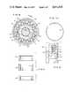
- FIG. 8is a view taken on line 8--8 of FIG. 6;
- FIG. 9is a view taken on line 9--9 of FIG. 8;
- FIG. 10is a top view of the split ring shown in FIG. 9.
- FIG. 11shows the upper, middle and lower solid rings.
- FIGS. 1 to 4There is shown in FIGS. 1 to 4 a tubing plug assembly, generally designated 10, which includes an upper tubular housing A, a lower tubular housing B into which housing A extends, and an inner mandrel C that is threadedly attached to the lower end of housing B.
- Housing Ais vertically movable on mandrel C.
- a seal ring member Sis positioned between the lower end of housing B and a nose plug E that is threadedly attached to the lower end of housing B.
- upper housing Ais shear pinned to mandrel C by a shear pin and housing A is in an upper position with respect to lower housing B.
- the lower portion of housing Ais provided wth a downwardly and inwardly extending locking taper.
- housing BThe upper portion of housing B is provided wth a plurality of locking dogs 12, which move laterally through windows 15 of housing B when engaged by the locking taper of upper housing A.
- plug assembly 10When plug assembly 10 is run into a tubing run T and seal ring S is seated on the tapered sealing surface 18 of tubing run T, the shear pin is sheared and the running tool moves the housing portion A downwardly in housing B causing locking dogs 12 to move outwardly through windows 15 to cause locking tapers 13 of dogs 12 to engage locking taper 17 of locking recess 16.
- taper 17 of recess 16is spaced too high and locking taper 13 of dogs 12 cannot engage 17 to cause downward movement of, and to exert downward pressure on, housing B.
- taper 17is spaced too low for locking dogs 12 to enter recess 16.
- the spacing of the locking taperis critical.
- the spacing or distances between surfaces 17 and 18 of tubing run Tare precisely selected so that seal ring S is properly loaded for sealing purposes against taper 18 when plug 10 is locked in its actuated position.
- FIGS. 5 through 11there is shown a tubing plug, generally designated 50, arranged in a tubing run or section 51.
- a locking recess 52is formed on the inner surface of tubing 51.
- Recess 52has a tapered surface 53 at its upper end.
- Tubing 51also has a tapered sealing surface 54 for engaging an annular crescent-shaped metal seal member 55 arranged between a cone-shaped end member 56 and a U-shaped housing 57.
- a shoulder 57b formed on the lower outer surface of housing 57 above seal member 55engages a ledge 51a formed on the inner surface of tubing section 51.
- seal member 55There is a potential problem of over yielding seal member 55 if it must absorb all of the locking load.
- seal member 55By having housing 57 shoulder out on ledge 51a, seal member 55 is only partially energized and the rest of the load is put into the contact of housing 57 and tubing section 51.
- the preloaded contact between housing 57 and tubing section 51also eliminates any relative movement between seal member 55 and sealing surface 54.
- the ledge and shoulderare included in FIG. 1 as prior art, that feature of the tubing plug is not part of the prior art.
- a shear pin 50ahas been sheared from connection to solid rod mandrel 66.
- the sheared portion of the plugis retained in the plug housing by an O-ring 50b.
- Each segment of lockdown rings 60 and 61has a half-cylinder bearing 60a and 61a, respectively, that contacts a mandrel 65 extending into housing 57.
- the outer surface of mandrel 65has a tapered section 65a.
- the surfaces on the upper set of lockdown rings 60have a 45° taper.
- the surfaces on the lower set of lockdown rings 61have a 20° taper.
- the taper 65a on mandrel 65is 4°.
- Solid rod mandrel 66extends through tapered mandrel 65 and threads into the lower end of housing 57. In the unlocked position of mandrel 65, a shoulder 70 formed on the inner surface of tapered mandrel 65 engages a shoulder 71 formed on rod mandrel 66. A series of locking dogs 75 surround tapered mandrel 65 above the upper solid ring 62.
- a split ring 76is positioned within each of the half-cylinder bearings 60a and 61a.
- the two sets of segmented expanding lock rings 60 and 61react with the three solid rings 62, 63, and 64 to provide a downward motion of, for example, 0.375 inches. This is achieved wth a locking recess taper depth of only 0.156 inches. Thus, a smaller OD tube can be used while gaining greater vertical makeup travel.
- the expanding lockdown rings 60 and 61consist of solid tapered rings that have been cut into several arcs.
- tapered mandrel 65When tapered mandrel 65 is forced down inside the arcs, the arcs are expanded to the outside diameter of tapered mandrel 65. As these arcs expand, they are wedged between the solid rings 62, 63 and 64 that have matching tapers.
- the solid ringsreact between the locking dogs 75 and the annular shoulder 57a in the housing to provide the downward movement.
- mandrel 65is driven down. As the mandrel moves down, the 4° taper on it forces locking dogs 75 outwardly. These locking dogs now “fall” into a relatively wide locking recess tapered groove. The locking dog/locking recess taper engagement is not relied on to energize the gasket.
- tapered mandrel 65continues downward movement, the first set of segmented lockdown rings 60 are contacted and expanded. Lockdown ring 60 has a 45° taper so that when it is expanded, a relatively large amount of wedging motion occurs. Such action takes up the "slop" between the locking dogs and their locking taper 53 of tubing 51, but does not energize gasket 55.
- the half-cylinder bearing 60ais free to rotate in the pockets on the lockdown ring. This allows the inside surface of the bearing to remain flush with the mandrel, even on the 4° tapered section of mandrel 66, and insures that the outward forces generated by the mandrel's wedging action will always act through the center of the lockdown rings and will not cock them. Additionally, this prevents a sharp edge from cutting into and stopping the mandrel and it provides a broader area to distribute the forces.
- the space-out of the mandrel taper and the solid rings and lockdown ringsis such that the upper set of lockdown rings 60 will not be contacted by the mandrel taper until the locking dogs 75 are fully expanded on the large OD of the mandrel. Similarly, the lower set of lockdown rings 61 will not be expanded until the upper set 60 is fully out.
- tapered mandrel 65continues downward movement and begins to expand the lower set of lockdown rings 61.
- This sethas a 20° taper. It provides enough movement to energize the gasket. The shallow taper allows much force to be directed into the gasket since little actual motion is required.
- the 4° taper on the mandrelis sufficient to ensure that the mandrel cannot be forced back up by forces from below. Only when the mandrel is pulled up from above are the lockdown rings and locking dogs free to fall back and allow plug removal.
Landscapes
- Life Sciences & Earth Sciences (AREA)
- Engineering & Computer Science (AREA)
- Geology (AREA)
- Mining & Mineral Resources (AREA)
- Physics & Mathematics (AREA)
- Environmental & Geological Engineering (AREA)
- Fluid Mechanics (AREA)
- General Life Sciences & Earth Sciences (AREA)
- Geochemistry & Mineralogy (AREA)
- Closures For Containers (AREA)
Abstract
Description
Claims (3)
Priority Applications (1)
| Application Number | Priority Date | Filing Date | Title |
|---|---|---|---|
| US06/861,791US4651818A (en) | 1986-05-12 | 1986-05-12 | Metal seal tubing plug |
Applications Claiming Priority (1)
| Application Number | Priority Date | Filing Date | Title |
|---|---|---|---|
| US06/861,791US4651818A (en) | 1986-05-12 | 1986-05-12 | Metal seal tubing plug |
Publications (1)
| Publication Number | Publication Date |
|---|---|
| US4651818Atrue US4651818A (en) | 1987-03-24 |
Family
ID=25336773
Family Applications (1)
| Application Number | Title | Priority Date | Filing Date |
|---|---|---|---|
| US06/861,791Expired - Fee RelatedUS4651818A (en) | 1986-05-12 | 1986-05-12 | Metal seal tubing plug |
Country Status (1)
| Country | Link |
|---|---|
| US (1) | US4651818A (en) |
Cited By (25)
| Publication number | Priority date | Publication date | Assignee | Title |
|---|---|---|---|---|
| US4784222A (en)* | 1987-09-17 | 1988-11-15 | Cameron Iron Works Usa, Inc. | Wellhead sealing assembly |
| US4796698A (en)* | 1986-05-28 | 1989-01-10 | Otis Engineering Corporation | Landing nipple and plug |
| US4869615A (en)* | 1988-03-23 | 1989-09-26 | Cameron Iron Works, Usa, Inc. | Tension leg joint |
| EP0468668A3 (en)* | 1990-07-25 | 1993-02-24 | Otis Engineering Corporation | Rotary locking system with metal seals |
| US5509476A (en)* | 1994-03-07 | 1996-04-23 | Halliburton Company | Short wellhead plug |
| EP0715056A3 (en)* | 1994-12-01 | 1997-05-02 | Cooper Cameron Corp | Blanking plug assembly |
| EP0687801A3 (en)* | 1994-06-14 | 1997-10-01 | Ssr International Ltd | Metal sealing wireline plug |
| US5685369A (en)* | 1996-05-01 | 1997-11-11 | Abb Vetco Gray Inc. | Metal seal well packer |
| US5901787A (en)* | 1995-06-09 | 1999-05-11 | Tuboscope (Uk) Ltd. | Metal sealing wireline plug |
| US6334488B1 (en) | 2000-01-11 | 2002-01-01 | Weatherford/Lamb, Inc. | Tubing plug |
| WO2002028560A3 (en)* | 2000-10-06 | 2002-06-13 | Obi Corp | Method and apparatus for expansion sealing concentric tubular structures |
| US20040055760A1 (en)* | 2002-09-20 | 2004-03-25 | Nguyen Philip D. | Method and apparatus for forming an annular barrier in a wellbore |
| US20050023003A1 (en)* | 2002-09-23 | 2005-02-03 | Echols Ralph H. | Annular isolators for tubulars in wellbores |
| US7108071B2 (en) | 2001-04-30 | 2006-09-19 | Weatherford/Lamb, Inc. | Automatic tubing filler |
| US20070074870A1 (en)* | 2003-05-22 | 2007-04-05 | Fmc Kongsberg Subsea As | Dual-type plug for wellhead |
| US20070289745A1 (en)* | 2004-04-24 | 2007-12-20 | Andrew Richards | Plug Setting and Retrieving Apparatus |
| WO2011084067A1 (en)* | 2010-01-07 | 2011-07-14 | Aker Subsea As | Subsea cap |
| US20120186805A1 (en)* | 2011-01-25 | 2012-07-26 | Baker Hughes Incorporated | Lock Mandrel Load Distribution Apparatus |
| US20120186806A1 (en)* | 2011-01-25 | 2012-07-26 | Baker Hughes Incorporated | Dog with Skirt to Transfer Housing Loads in a Subterranean Tool |
| US20130292127A1 (en)* | 2012-05-01 | 2013-11-07 | Vetco Gray U.K. Limited | Plug installation system and method |
| US20140166315A1 (en)* | 2012-12-17 | 2014-06-19 | Baker Hughes Incorporated | Lock assembly with cageless dogs |
| WO2014099588A1 (en)* | 2012-12-17 | 2014-06-26 | Baker Hughes Incorporated | High pressure lock assembly |
| CN104832124A (en)* | 2015-05-26 | 2015-08-12 | 大庆金祥寓科技有限公司 | Safe blowout prevention working barrel |
| US9464497B2 (en) | 2010-01-07 | 2016-10-11 | Aker Subsea As | Seal holder and method for sealing a bore |
| CN110454112A (en)* | 2019-07-29 | 2019-11-15 | 中国海洋石油集团有限公司 | A kind of coiled tubing test blanking plug |
Citations (2)
| Publication number | Priority date | Publication date | Assignee | Title |
|---|---|---|---|---|
| US4178992A (en)* | 1978-01-30 | 1979-12-18 | Exxon Production Research Company | Metal seal tubing plug |
| US4595053A (en)* | 1984-06-20 | 1986-06-17 | Hughes Tool Company | Metal-to-metal seal casing hanger |
- 1986
- 1986-05-12USUS06/861,791patent/US4651818A/ennot_activeExpired - Fee Related
Patent Citations (2)
| Publication number | Priority date | Publication date | Assignee | Title |
|---|---|---|---|---|
| US4178992A (en)* | 1978-01-30 | 1979-12-18 | Exxon Production Research Company | Metal seal tubing plug |
| US4595053A (en)* | 1984-06-20 | 1986-06-17 | Hughes Tool Company | Metal-to-metal seal casing hanger |
Cited By (61)
| Publication number | Priority date | Publication date | Assignee | Title |
|---|---|---|---|---|
| US4796698A (en)* | 1986-05-28 | 1989-01-10 | Otis Engineering Corporation | Landing nipple and plug |
| US4784222A (en)* | 1987-09-17 | 1988-11-15 | Cameron Iron Works Usa, Inc. | Wellhead sealing assembly |
| US4869615A (en)* | 1988-03-23 | 1989-09-26 | Cameron Iron Works, Usa, Inc. | Tension leg joint |
| EP0468668A3 (en)* | 1990-07-25 | 1993-02-24 | Otis Engineering Corporation | Rotary locking system with metal seals |
| US5509476A (en)* | 1994-03-07 | 1996-04-23 | Halliburton Company | Short wellhead plug |
| EP0687801A3 (en)* | 1994-06-14 | 1997-10-01 | Ssr International Ltd | Metal sealing wireline plug |
| EP0715056A3 (en)* | 1994-12-01 | 1997-05-02 | Cooper Cameron Corp | Blanking plug assembly |
| US5901787A (en)* | 1995-06-09 | 1999-05-11 | Tuboscope (Uk) Ltd. | Metal sealing wireline plug |
| US5685369A (en)* | 1996-05-01 | 1997-11-11 | Abb Vetco Gray Inc. | Metal seal well packer |
| US6334488B1 (en) | 2000-01-11 | 2002-01-01 | Weatherford/Lamb, Inc. | Tubing plug |
| WO2002028560A3 (en)* | 2000-10-06 | 2002-06-13 | Obi Corp | Method and apparatus for expansion sealing concentric tubular structures |
| US6530574B1 (en)* | 2000-10-06 | 2003-03-11 | Gary L. Bailey | Method and apparatus for expansion sealing concentric tubular structures |
| GB2384202A (en)* | 2000-10-06 | 2003-07-23 | Obi Corp | Method and apparatus for expansion sealing concentric tubular structures |
| GB2384202B (en)* | 2000-10-06 | 2004-08-18 | Obi Corp | Method and apparatus for expansion sealing concentric tubular structures |
| US7108071B2 (en) | 2001-04-30 | 2006-09-19 | Weatherford/Lamb, Inc. | Automatic tubing filler |
| US20040055760A1 (en)* | 2002-09-20 | 2004-03-25 | Nguyen Philip D. | Method and apparatus for forming an annular barrier in a wellbore |
| US7404437B2 (en) | 2002-09-23 | 2008-07-29 | Halliburton Energy Services, Inc. | Annular isolators for expandable tubulars in wellbores |
| US20070267201A1 (en)* | 2002-09-23 | 2007-11-22 | Halliburton Energy Services, Inc. | Annular Isolators for Expandable Tubulars in Wellbores |
| US20050092485A1 (en)* | 2002-09-23 | 2005-05-05 | Brezinski Michael M. | Annular isolators for expandable tubulars in wellbores |
| US7216706B2 (en) | 2002-09-23 | 2007-05-15 | Halliburton Energy Services, Inc. | Annular isolators for tubulars in wellbores |
| US20070114016A1 (en)* | 2002-09-23 | 2007-05-24 | Halliburton Energy Services, Inc. | Annular Isolators for Expandable Tubulars in Wellbores |
| US20070114018A1 (en)* | 2002-09-23 | 2007-05-24 | Halliburton Energy Services, Inc. | Annular Isolators for Expandable Tubulars in Wellbores |
| US20070114044A1 (en)* | 2002-09-23 | 2007-05-24 | Halliburton Energy Services, Inc. | Annular Isolators for Expandable Tubulars in Wellbores |
| US20070114017A1 (en)* | 2002-09-23 | 2007-05-24 | Halliburton Energy Services, Inc. | Annular Isolators for Expandable Tubulars in Wellbores |
| US7252142B2 (en) | 2002-09-23 | 2007-08-07 | Halliburton Energy Services, Inc. | Annular isolators for expandable tubulars in wellbores |
| USRE41118E1 (en) | 2002-09-23 | 2010-02-16 | Halliburton Energy Services, Inc. | Annular isolators for expandable tubulars in wellbores |
| US7299882B2 (en) | 2002-09-23 | 2007-11-27 | Halliburton Energy Services, Inc. | Annular isolators for expandable tubulars in wellbores |
| US20080251250A1 (en)* | 2002-09-23 | 2008-10-16 | Halliburton Energy Services, Inc. | Annular Isolators for Expandable Tubulars in Wellbores |
| US7320367B2 (en) | 2002-09-23 | 2008-01-22 | Halliburton Energy Services, Inc. | Annular isolators for expandable tubulars in wellbores |
| US7363986B2 (en) | 2002-09-23 | 2008-04-29 | Halliburton Energy Services, Inc. | Annular isolators for expandable tubulars in wellbores |
| US20050023003A1 (en)* | 2002-09-23 | 2005-02-03 | Echols Ralph H. | Annular isolators for tubulars in wellbores |
| US7654329B2 (en)* | 2003-05-22 | 2010-02-02 | Fmc Kongsberg Subsea As | Dual-type plug for wellhead |
| US20070074870A1 (en)* | 2003-05-22 | 2007-04-05 | Fmc Kongsberg Subsea As | Dual-type plug for wellhead |
| US20070289745A1 (en)* | 2004-04-24 | 2007-12-20 | Andrew Richards | Plug Setting and Retrieving Apparatus |
| US8028752B2 (en)* | 2004-04-24 | 2011-10-04 | Expro North Sea Limited | Plug setting and retrieving apparatus |
| CN102713133A (en)* | 2010-01-07 | 2012-10-03 | 阿克海底公司 | Subsea cap |
| US8950474B2 (en) | 2010-01-07 | 2015-02-10 | Aker Subsea As | Subsea cap |
| US9464497B2 (en) | 2010-01-07 | 2016-10-11 | Aker Subsea As | Seal holder and method for sealing a bore |
| GB2488723A (en)* | 2010-01-07 | 2012-09-05 | Aker Subsea As | Subsea cap |
| WO2011084067A1 (en)* | 2010-01-07 | 2011-07-14 | Aker Subsea As | Subsea cap |
| GB2488723B (en)* | 2010-01-07 | 2015-10-14 | Aker Subsea As | Subsea cap |
| CN102713133B (en)* | 2010-01-07 | 2015-05-27 | 阿克海底公司 | Subsea cap |
| AU2011204030B2 (en)* | 2010-01-07 | 2015-03-05 | Aker Subsea As | Subsea cap |
| US8651182B2 (en)* | 2011-01-25 | 2014-02-18 | Baker Hughes Incorporated | Dog with skirt to transfer housing loads in a subterranean tool |
| US20120186805A1 (en)* | 2011-01-25 | 2012-07-26 | Baker Hughes Incorporated | Lock Mandrel Load Distribution Apparatus |
| US20120186806A1 (en)* | 2011-01-25 | 2012-07-26 | Baker Hughes Incorporated | Dog with Skirt to Transfer Housing Loads in a Subterranean Tool |
| US8596350B2 (en)* | 2011-01-25 | 2013-12-03 | Baker Hughes Incorporated | Lock mandrel load distribution apparatus |
| US20130292127A1 (en)* | 2012-05-01 | 2013-11-07 | Vetco Gray U.K. Limited | Plug installation system and method |
| US9109419B2 (en)* | 2012-05-01 | 2015-08-18 | Vetco Gray U.K. Limited | Plug installation system and method |
| US9212528B2 (en)* | 2012-12-17 | 2015-12-15 | Baker Hughes Incorporated | Lock assembly with cageless dogs |
| NO20150712A1 (en)* | 2012-12-17 | 2015-06-03 | Baker Hughes Inc | Lock Assembly With cageless dogs |
| WO2014099589A1 (en)* | 2012-12-17 | 2014-06-26 | Baker Hughes Incorporated | Lock assembly with cageless dogs |
| GB2526003A (en)* | 2012-12-17 | 2015-11-11 | Baker Hughes Inc | Lock assembly with cageless dogs |
| US20140166315A1 (en)* | 2012-12-17 | 2014-06-19 | Baker Hughes Incorporated | Lock assembly with cageless dogs |
| GB2528178A (en)* | 2012-12-17 | 2016-01-13 | Baker Hughes Inc | High pressure lock assembly |
| GB2526003B (en)* | 2012-12-17 | 2016-05-25 | Baker Hughes Inc | Lock assembly with cageless dogs |
| WO2014099588A1 (en)* | 2012-12-17 | 2014-06-26 | Baker Hughes Incorporated | High pressure lock assembly |
| GB2528178B (en)* | 2012-12-17 | 2017-07-26 | Baker Hughes Inc | High pressure lock assembly |
| NO348401B1 (en)* | 2012-12-17 | 2025-01-13 | Baker Hughes Holdings Llc | Lock Assembly With cageless dogs |
| CN104832124A (en)* | 2015-05-26 | 2015-08-12 | 大庆金祥寓科技有限公司 | Safe blowout prevention working barrel |
| CN110454112A (en)* | 2019-07-29 | 2019-11-15 | 中国海洋石油集团有限公司 | A kind of coiled tubing test blanking plug |
Similar Documents
| Publication | Publication Date | Title |
|---|---|---|
| US4651818A (en) | Metal seal tubing plug | |
| US5060724A (en) | Casing hanger seal locking mechanism with detent | |
| US4949787A (en) | Casing hanger seal locking mechanism | |
| US5307879A (en) | Positive lockdown for metal seal | |
| US4714111A (en) | Weight/pressure set pack-off for subsea wellhead systems | |
| US4719971A (en) | Metal-to-metal/elastomeric pack-off assembly for subsea wellhead systems | |
| US9133678B2 (en) | Metal annulus seal | |
| US4469172A (en) | Self-energizing locking mechanism | |
| US4751965A (en) | Wellhead seal assembly | |
| US4790572A (en) | Tapered wedge packoff assembly for a casing hanger | |
| US3797864A (en) | Combined metal and elastomer seal | |
| US4665979A (en) | Metal casing hanger seal with expansion slots | |
| US4641708A (en) | Casing hanger locking device | |
| US4131287A (en) | Annular seal | |
| US4488740A (en) | Breech block hanger support | |
| US6520263B2 (en) | Retaining apparatus for use in a wellhead assembly and method for using the same | |
| US5174376A (en) | Metal-to-metal annulus packoff for a subsea wellhead system | |
| US4691780A (en) | Subsea wellhead structure | |
| US6510895B1 (en) | Energized sealing cartridge for annulus sealing between tubular well components | |
| US8851185B2 (en) | Dual metal seal system | |
| US4702481A (en) | Wellhead pack-off with undulated metallic seal ring section | |
| US4178992A (en) | Metal seal tubing plug | |
| US3933202A (en) | Apparatus for setting and locking packing assemblies in wellheads | |
| US5129660A (en) | Seal assembly for a well housing hanger structure | |
| US4896721A (en) | Locator shifter tool |
Legal Events
| Date | Code | Title | Description |
|---|---|---|---|
| AS | Assignment | Owner name:EXXON PRODUCTION RESEARCH COMPANY, A CORP. OF DE. Free format text:ASSIGNMENT OF ASSIGNORS INTEREST.;ASSIGNOR:CHILDERS, THOMAS W.;REEL/FRAME:004611/0174 Effective date:19860430 Owner name:EXXON PRODUCTION RESEARCH COMPANY, A CORP. OF DE. Free format text:ASSIGNMENT OF ASSIGNORS INTEREST.;ASSIGNOR:JOHNSON, DALE V.;REEL/FRAME:004611/0176 Effective date:19860428 Owner name:EXXON PRODUCTION RESEARCH COMPANY, A CORP. OF DE., Free format text:ASSIGNMENT OF ASSIGNORS INTEREST;ASSIGNOR:CHILDERS, THOMAS W.;REEL/FRAME:004611/0174 Effective date:19860430 Owner name:EXXON PRODUCTION RESEARCH COMPANY, A CORP. OF DE., Free format text:ASSIGNMENT OF ASSIGNORS INTEREST;ASSIGNOR:JOHNSON, DALE V.;REEL/FRAME:004611/0176 Effective date:19860428 | |
| FPAY | Fee payment | Year of fee payment:4 | |
| REMI | Maintenance fee reminder mailed | ||
| LAPS | Lapse for failure to pay maintenance fees | ||
| FP | Lapsed due to failure to pay maintenance fee | Effective date:19950329 | |
| STCH | Information on status: patent discontinuation | Free format text:PATENT EXPIRED DUE TO NONPAYMENT OF MAINTENANCE FEES UNDER 37 CFR 1.362 |