US4651740A - Implant and control apparatus and method employing at least one tuning fork - Google Patents
Implant and control apparatus and method employing at least one tuning forkDownload PDFInfo
- Publication number
- US4651740A US4651740AUS06/703,134US70313485AUS4651740AUS 4651740 AUS4651740 AUS 4651740AUS 70313485 AUS70313485 AUS 70313485AUS 4651740 AUS4651740 AUS 4651740A
- Authority
- US
- United States
- Prior art keywords
- implanted
- transducer
- signal
- tuning fork
- acoustic
- Prior art date
- Legal status (The legal status is an assumption and is not a legal conclusion. Google has not performed a legal analysis and makes no representation as to the accuracy of the status listed.)
- Expired - Lifetime
Links
- 238000000034methodMethods0.000titleclaimsabstractdescription29
- 239000007943implantSubstances0.000titleclaimsdescription12
- 238000012545processingMethods0.000claimsdescription17
- 230000004044responseEffects0.000claimsdescription16
- 230000000977initiatory effectEffects0.000claims6
- 238000001914filtrationMethods0.000claims3
- 230000003068static effectEffects0.000claims3
- 230000002463transducing effectEffects0.000claims2
- 230000004075alterationEffects0.000claims1
- 102100026827Protein associated with UVRAG as autophagy enhancerHuman genes0.000abstractdescription49
- 101710102978Protein associated with UVRAG as autophagy enhancerProteins0.000abstractdescription49
- 230000000747cardiac effectEffects0.000abstractdescription34
- 230000001276controlling effectEffects0.000abstractdescription6
- 230000002596correlated effectEffects0.000abstractdescription4
- 235000014676Phragmites communisNutrition0.000description6
- 230000008859changeEffects0.000description6
- 238000010586diagramMethods0.000description6
- 230000005540biological transmissionEffects0.000description4
- 208000001871TachycardiaDiseases0.000description3
- 230000001746atrial effectEffects0.000description3
- 230000000875corresponding effectEffects0.000description3
- 230000006870functionEffects0.000description3
- 210000003205muscleAnatomy0.000description3
- 230000006794tachycardiaEffects0.000description3
- 238000001514detection methodMethods0.000description2
- 238000007920subcutaneous administrationMethods0.000description2
- 239000003814drugSubstances0.000description1
- 229940079593drugDrugs0.000description1
- 238000012377drug deliveryMethods0.000description1
- 230000000694effectsEffects0.000description1
- 230000005672electromagnetic fieldEffects0.000description1
- 230000007613environmental effectEffects0.000description1
- 230000008571general functionEffects0.000description1
- 238000002513implantationMethods0.000description1
- 238000012986modificationMethods0.000description1
- 230000004048modificationEffects0.000description1
- 238000012544monitoring processMethods0.000description1
- 210000004165myocardiumAnatomy0.000description1
- 210000000056organAnatomy0.000description1
- 230000037368penetrate the skinEffects0.000description1
- 230000008569processEffects0.000description1
- 230000003252repetitive effectEffects0.000description1
- 230000035945sensitivityEffects0.000description1
- 230000004936stimulating effectEffects0.000description1
- 238000012360testing methodMethods0.000description1
- 210000001519tissueAnatomy0.000description1
- 230000002861ventricularEffects0.000description1
- 230000000007visual effectEffects0.000description1
Images


Classifications
- A—HUMAN NECESSITIES
- A61—MEDICAL OR VETERINARY SCIENCE; HYGIENE
- A61N—ELECTROTHERAPY; MAGNETOTHERAPY; RADIATION THERAPY; ULTRASOUND THERAPY
- A61N1/00—Electrotherapy; Circuits therefor
- A61N1/18—Applying electric currents by contact electrodes
- A61N1/32—Applying electric currents by contact electrodes alternating or intermittent currents
- A61N1/36—Applying electric currents by contact electrodes alternating or intermittent currents for stimulation
- A61N1/372—Arrangements in connection with the implantation of stimulators
- A61N1/37211—Means for communicating with stimulators
- A61N1/37217—Means for communicating with stimulators characterised by the communication link, e.g. acoustic or tactile
Definitions
- the present inventionrelates generally to methods for changing internal parameters of implanted devices, such as a cardiac pacemaker, and more particularly to means, such as the use of a vibration generating external device, for generating a programmed response within the implant.
- Prior methods for controlling or changing the parameters of an implanted cardiac pacemakerhave included the application of a permanent magnet wherein the magnetic field generated causes a magnetic reed switch within the pacemaker to close. This actuation of the magnetic reed switch is then used to activate or deactivate a circuit or to set parameters within the pacemaker.
- an output generated by a circuit which is generally inhibited when cardiac activity exceeds a preset ratecan be converted by application of the magnet to an output which stimulates cardiac rate at a preset value.
- an external programming devicegenerates pulsating magnetic fields and coded signals which are transmitted to a reed switch within the implanted cardiac pacer.
- the signalis then decoded by the implanted pacer through detection of the repetitive actuation of the reed switch and provides, in a programmed response thereto, a set of parameters within the implanted pacer.
- An examplewould be to change a cardiac pacer from atrial pacing to ventricular pacing or from atrial fixed-rate pacing to atrial inhibited pacing or to change the cardiac stimulating current from 7 milliamps to 5 milliamps.
- the Summers U.S. Pat. No. 3,672,352discloses a system for monitoring a condition of a body function or organ or of a device implanted within a body and includes an implanted sensor or transducer connected to a signal generating device.
- This signal generating deviceis arranged to generate an audible, visual or heat signal representing the condition of the implanted device, as, for example, the status of the battery charge. More particularly, this signal generating device uses a variation in intensity, such as an on/off code, to transmit information about the condition of the implanted device through the skin to a signal receiver.
- an implanted devicewhose parameters can be non-invasively changed by the use of acoustic vibrations of relatively pure frequencies such as those generated by a tuning fork.
- the deviceis implanted within the patient and has a circuit designed to respond to one frequency. These acoustic vibrations are converted by the transducer into electrical signals which can then be transmitted through an electrical signal amplifier to a tuned filter for selection of the peak signal for processing in a processing circuit.
- the processing circuitthen causes a response such as, for example, switching the pacer from the inhibited mode to a fixed rate pacing mode at a preset rate.
- a method of controlling an implanted deviceby applying a vibrating tuning fork directly adjacent the skin overlying the implanted device such as a pacer.
- a frequency selective detector in the pacercan then respond and select a desired function according to programming.
- tuning forkscould be applied in a coded sequence . Since tuning forks generate relatively pure frequencies, difficulties with environmental interference would be minimized.
- tuning fork actuated systemposes extraordinary potential since tuning forks are readily available, require no power supply, are transportable, safe and easy to use. They are also standardized and generally inexpensive. Further, certain frequencies can be standardized for programming standardized operation, i.e., frequency "A” can be used for programming the pacer into a recognized safe operation; frequency “B” can be used to initiate a "dump” of information held within the implant, and frequency “C” can be used to generate an emergency operation, such as to terminate a tachycardia episode.
- this method of controlling an implanted devicecan be used to control the type or quantity of a drug to be delivered by an implanted drug delivery system.
- this tuning fork method of controlling an implantcan be used together with an electromagnetic control system to provide increased security for the implanted device whereby predetermined combinations of the magnet and tuning fork can be used to accomplish objectives.
- the method of operationemploys the selection of a tuning fork at the appropriate frequency corresponding to the frequency of the tuning filter within the circuitry of the implant.
- a physicianstrikes the tuning fork against a table or other hard surface to generate the tuning fork frequency.
- the vibrating tuning forkis then held over the skin of the patient proximate the implanted device and acoustic vibrations are caused to penetrate the tissue and be received by the implanted device. These acoustic vibrations are then detected by the transducer, amplified and filtered, and finally received by the processing circuitry whereupon an appropriate programmed mode is initiated.
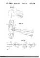
- FIG. 1illustrates a diagram of a cardiac pacer implanted within the body of a patient and shows a tuning fork positioned near the skin over the implanted pacer.
- FIG. 2illustrates a cardiac pacer implanted in a subcutaneous pocket formed between the skin and muscle and shows acoustic vibrations being transmitted through the skin to the cardiac pacer.
- FIG. 3is a block circuit diagram of the pacer circuitry of the present invention mounted within the implanted cardiac pacer and shows a mechanical-electrical transducer for detecting the tuning fork vibrations, an amplifier, a tuned filter and processing circuitry.
- FIG. 4illustrates the cardiac pacer implanted in a subcutaneous pocket between the skin and muscle whereby the tuning fork is applied in a second mode of operation.
- FIG. 5illustrates the application of a tuning fork and a permanent magnet in yet a further method employing the tuning fork actuated circuitry of the present invention.
- FIG. 6is a block circuit diagram of the pacer circuitry of another embodiment of the present invention in which three tuned filters are utilized, each tuned to a different frequency.
- FIG. 7is a flow chart of the operation sequence of the pacer circuitry of the present invention.
- FIG. 8illustrates a modified form of the FIG. 4 device using a resonance box.
- FIG. 1there is illustrated therein a cardiac pacer 10 implanted within a body 12 of a patient.
- a cardiac pacer 10implanted within a body 12 of a patient.
- FIG. 1depicts a cardiac pacer
- a pervenous lead 14extending from the cardiac pacer 10 for connection to the heart muscle (not shown).
- this pacer 10can be arranged and positioned in a pocket 22 formed between the skin 24 and the muscle 26 of a patient.
- this cardiac pacer 10is arranged to respond in a preprogrammed manner to the application of acoustic vibrations 28 impinged thereon. These vibrations are preferably generated by a pure frequency device, such as a tuning fork 30 and are transmitted through the skin 24 to the pacer 10.
- a pure frequency devicesuch as a tuning fork 30
- FIG. 3there is shown therein a block circuit diagram of an electrical circuit 38 mounted in the pacer 10 for carrying out the teachings of the present invention.
- the circuit 38is mounted within the cardiac pacer 10 or other implanted device.
- the circuit 38is designed to respond to a single frequency.
- an incoming vibration from the tuning fork 30is reduced to an electrical signal by a transducer 40, amplified by an amplifier 42 and then fed to a frequency selection circuit 43 comprising a tuned filter 44 for actuation of processing circuitry 46.
- the transducer 40converts the impinging acoustic vibrations 28 into corresponding electrical signals.
- this transducer 40would be a microphone or piezoelectric element.
- the electrical signals from the transducer 40are then amplified by the amplifier 42 and fed directly to a tuned filter 44.
- This tuned filter 44represents electrical circuitry designed to select the peak signal and its corresponding frequency and to transmit the chosen frequency electrically to the processing circuitry 46.
- This processing circuitry 46is generally a programmable electronic device, such as a microprocessor, arranged to respond in a programmed manner to preselected frequencies.
- the tuned filter 44may be further explained by reference to the expected noise or unwanted signals which may be processed through the transducer and amplifier. Generally speaking, extraneous frequencies may be processed but will not represent a pure frequency, while the tuned filter 44 is designed to select a predetermined pure frequency. Acting upon the electrical signal generated in response to the acoustical vibrations, the tuned filter 44 is designed to detect the electrical signal having a large component correlated with the desired pure frequency. The strong presence of other unwanted frequencies would result in a negative response by the circuitry 43. Thus, there must be present a single frequency of sufficiently large components in order to cause a parameter change within the implanted pacer 10.
- the basic operation of the circuitry 38 of the present inventionis initiated after implantation when a change in parameters in the implanted pacer 10 is required or at some other appropriate time for test purposes.
- a tuning fork 30which correlates with the frequency to which the tuned filter 44 has been set is chosen and is caused to vibrate.
- a single member end 50(as shown in FIGS. 1 and 2) is then held against the skin 24 of the patient 12 over the implanted cardiac pacer 10. The mechanical vibrations resulting from vibration of the single member end 50 are caused to emanate from the tuning fork 36 and are transmitted through the skin 24 to the cardiac pacer 10. Impedance matching may be facilitated by using a resonance box 52 which is positioned between the tuning fork 30 and the patient as shown in FIG. 8.
- the tuning fork 30is arranged so that forked ends 54, 56 are positioned over the skin adjacent to the implanted cardiac pacer 10. Similarly, in this position, the acoustic vibrations are transmitted across the air layer between the tuning fork 30 and the skin 24, through the skin 24, and to the cardiac pacer 10.
- the vibrations reaching the cardiac pacer 10are sensed by the transducer 40 and reduced to electrical signals thereby, amplified and fed to the tuned filter 44 where the frequency selection process takes place.
- the processing circuitry 46is electrically coupled to the output of the tuned filter 44 and programmed to respond to the detected signals passed through the tuned filter 44.
- a typical application of the basic operationwould involve programming a cardiac pacer 10 to "stat" parameters.
- the programmable circuitry 46would be designed to respond to the detection of a predetermined frequency and to respond by programming the cardiac pacer to the "stat" parameters.
- a rapid burst of electrical pulses from the cardiac pacer 10can be used to treat such condition.
- a tuning fork 30 generated vibrating signalwould be applied near the skin 24 over the cardiac pacer 10 containing the transducer 40 and tuning filter circuitry 43. The vibrations would then be processed through the transducer 40, amplified, and the peak frequency selected by the tuned filter 44 and fed to the programmed electronic circuitry 46.
- the programmed electronic circuitry 46Upon receipt of the predetermined frequency, the programmed electronic circuitry 46 will select a set of parameters to cause the pacer 10 to generate a rapid burst of electrical pulses to disrupt the tachycardia episode and would then subsequently reprogram the cardiac pacer 10 to the "stat" parameters.
- additional security for the devicecan be incorporated by utilizing a magnetic switch.
- a magnetic switchAs shown in FIG. 5, the application of a permanent magnet 58 near the skin overlying the cardiac pacer 10 can be used to close a magnetic reed switch generally identified by reference numeral 61 in FIG. 3 connected in series between transducer 42 and amplifier 42, or generally identified by reference numeral 63 connected to the processing circuitry 70 in FIG. 6 in the pacer 10.
- This closure of the reed switchcan be used to convert the cardiac pacer 10 to a preset mode of operation, or to enable the cardiac pacer 10 for transmission of the mechanical vibrations through the skin 24 into the pacer 10 whereupon the implanted transducer 40 responds thereto.
- This application of the tuning fork 30can be arranged to change other parameters of the cardiac pacer 10 such as sensitivity, rate, output, or to initiate a sequential change of parameters according to a preprogrammed sequence.
- the programming circuitry 46can be arranged to place the cardiac pacer 10 into a preprogrammed mode on removal of the tuning fork 30.
- FIG. 6there is shown a block circuit diagram of another embodiment of the control circuitry of the present invention.
- This circuitryis identified generally with reference numeral 59 and includes a plurality of (three) tuned filters 60, 62 and 64.
- Each tuned filter 60, 62 and 64is electrically coupled to the output of an amplifier 66 as in the previously described circuitry 38.
- the input to this amplifier 66comes from a mechanical to electrical transducer 68.
- this transducer 68can be a microphone or piezoelectric element arranged to receive the pure frequency mechanical vibrations from the tuning fork 30 and to generate an electrical signal correlated thereto.
- the signalis then fed to the amplifier 66 and, once amplified, to the bank 69 of tuned filters 60, 62 and 64.
- a plurality of correlated frequencieswill be presented to the tuned filter bank 69.
- programmed processing circuitry 70can be arranged to respond to the separate output of each.
- the programmed processing circuitry 70can be arranged to respond to a coded array of simultaneously input frequencies and to generate a preprogrammed pattern of parameters in response thereto or, either in the alternative or in combination therewith, to respond to a predetermined sequence of predetermined frequencies.
- FIG. 7depicting a flow diagram of the signal processing protocol carried out with the implanted pacer 10.
- the operatorselects a tuning fork 30 or other pure frequency generator of the desired frequency.
- the frequency generating device or tuning fork 30is placed on or near the skin 24 overlying the implanted device, e.g. pacer 10, in a manner arranged to direct the mechanical vibrations through the skin 24 to the circuitry 38 or 59.
- the implanted devicee.g. pacer 10
- the transducer 40 or 68 of the circuitry 38 or 59is arranged to respond to the incoming mechanical vibration and to generate electrical signals correlating thereto.
- the signal generated by the transduceris then caused to be processed through an amplifier and fed to one or more tuned filters for frequency selection in the next step.
- selected signal or signals filtered by the frequency selection circuitry comprising the tuned filtersare received by the programmed electronic processing circuitry 46 or 70 which is arranged to respond to the incoming frequencies and provide responsive changes in control parameters for the implanted device 10.
Landscapes
- Health & Medical Sciences (AREA)
- Radiology & Medical Imaging (AREA)
- Acoustics & Sound (AREA)
- Engineering & Computer Science (AREA)
- Biomedical Technology (AREA)
- Nuclear Medicine, Radiotherapy & Molecular Imaging (AREA)
- Physics & Mathematics (AREA)
- Life Sciences & Earth Sciences (AREA)
- Animal Behavior & Ethology (AREA)
- General Health & Medical Sciences (AREA)
- Public Health (AREA)
- Veterinary Medicine (AREA)
- Electrotherapy Devices (AREA)
Abstract
Description
Claims (21)
Priority Applications (1)
| Application Number | Priority Date | Filing Date | Title |
|---|---|---|---|
| US06/703,134US4651740A (en) | 1985-02-19 | 1985-02-19 | Implant and control apparatus and method employing at least one tuning fork |
Applications Claiming Priority (1)
| Application Number | Priority Date | Filing Date | Title |
|---|---|---|---|
| US06/703,134US4651740A (en) | 1985-02-19 | 1985-02-19 | Implant and control apparatus and method employing at least one tuning fork |
Publications (1)
| Publication Number | Publication Date |
|---|---|
| US4651740Atrue US4651740A (en) | 1987-03-24 |
Family
ID=24824149
Family Applications (1)
| Application Number | Title | Priority Date | Filing Date |
|---|---|---|---|
| US06/703,134Expired - LifetimeUS4651740A (en) | 1985-02-19 | 1985-02-19 | Implant and control apparatus and method employing at least one tuning fork |
Country Status (1)
| Country | Link |
|---|---|
| US (1) | US4651740A (en) |
Cited By (52)
| Publication number | Priority date | Publication date | Assignee | Title |
|---|---|---|---|---|
| US5391188A (en)* | 1992-05-01 | 1995-02-21 | Medtronic, Inc. | Low cost implantable medical device |
| US5620475A (en)* | 1994-04-25 | 1997-04-15 | Siemens Elema Ab | Extracorporeally controllable medical implant and method for operating same |
| US5749909A (en)* | 1996-11-07 | 1998-05-12 | Sulzer Intermedics Inc. | Transcutaneous energy coupling using piezoelectric device |
| US5755737A (en)* | 1996-12-13 | 1998-05-26 | Medtronic, Inc. | Method and apparatus for diagnosis and treatment of arrhythmias |
| GB2354949A (en)* | 1999-07-26 | 2001-04-11 | Zuli Holdings Ltd | Implanted medical device for medicament release or electro-therapy powered by an ultrasound source external to the body |
| WO2001028627A1 (en)* | 1999-10-20 | 2001-04-26 | Cardiac Pacemakers, Inc. | Implantable medical device with voice responding and recording capacity |
| WO2002032502A1 (en)* | 2000-10-16 | 2002-04-25 | Remon Medical Technologies Ltd. | Acoustic switch and apparatus and methods for using acoustic switches within a body |
| US20020177782A1 (en)* | 2000-10-16 | 2002-11-28 | Remon Medical Technologies, Ltd. | Barometric pressure correction based on remote sources of information |
| WO2003043688A1 (en)* | 2001-11-19 | 2003-05-30 | Remon Medical Technologies Ltd | Systems and methods for communicating with implantable devices |
| US6622049B2 (en)* | 2000-10-16 | 2003-09-16 | Remon Medical Technologies Ltd. | Miniature implantable illuminator for photodynamic therapy |
| US6763268B2 (en)* | 2001-02-20 | 2004-07-13 | Biophan Technologies, Inc. | Electromagnetic interference immune tissue invasive system |
| US6764446B2 (en) | 2000-10-16 | 2004-07-20 | Remon Medical Technologies Ltd | Implantable pressure sensors and methods for making and using them |
| US6788973B2 (en) | 2002-04-02 | 2004-09-07 | Medtronic, Inc. | Apparatus and method to discriminate between telemetry downlink signals and noise in an implanted device |
| US20040204744A1 (en)* | 2003-04-14 | 2004-10-14 | Remon Medicaltechnologies Ltd. | Apparatus and methods using acoustic telemetry for intrabody communications |
| US20050137490A1 (en)* | 2001-04-11 | 2005-06-23 | Cardiac Pacemakers, Inc. | Apparatus and method for outputting heart sounds |
| US20070000372A1 (en)* | 2005-04-13 | 2007-01-04 | The Cleveland Clinic Foundation | System and method for providing a waveform for stimulating biological tissue |
| US20070060959A1 (en)* | 2005-09-09 | 2007-03-15 | Cardiac Pacemakers, Inc. | Using implanted sensors for feedback control of implanted medical devices |
| US20070078498A1 (en)* | 2005-04-13 | 2007-04-05 | The Cleveland Clinic Foundation And Intelect Medical, Inc. | System and method for providing a waveform for stimulating biological tissue |
| US20070162090A1 (en)* | 2006-01-10 | 2007-07-12 | Abraham Penner | Body attachable unit in wireless communication with implantable devices |
| US20070250126A1 (en)* | 2006-04-25 | 2007-10-25 | Cardiac Pacemakers, Inc. | System and method for waking an implantable medical device from a sleep state |
| US20080021333A1 (en)* | 2006-07-21 | 2008-01-24 | Cardiac Pacemakers, Inc. | Multiple sensor deployment |
| USD560709S1 (en)* | 2007-05-30 | 2008-01-29 | Unk Guitars, Llc. | Guitar headstock |
| US20080077440A1 (en)* | 2006-09-26 | 2008-03-27 | Remon Medical Technologies, Ltd | Drug dispenser responsive to physiological parameters |
| US20080108915A1 (en)* | 2000-10-16 | 2008-05-08 | Remon Medical Technologies Ltd. | Acoustically powered implantable stimulating device |
| US20080171941A1 (en)* | 2007-01-12 | 2008-07-17 | Huelskamp Paul J | Low power methods for pressure waveform signal sampling using implantable medical devices |
| US20080243210A1 (en)* | 2007-03-26 | 2008-10-02 | Eyal Doron | Biased acoustic switch for implantable medical device |
| RU2337412C1 (en)* | 2007-02-02 | 2008-10-27 | Виктор Эдуардович Гюнтер | Acoustic oscillator |
| US20080312553A1 (en)* | 2007-06-14 | 2008-12-18 | Timmons Michael J | Intracorporeal pressure measurement devices and methods |
| US20090177251A1 (en)* | 2008-01-07 | 2009-07-09 | Paul Huelskamp | System And Method For In Situ Trimming Of Oscillators In A Pair Of Implantable Medical Devices |
| US20090198307A1 (en)* | 2008-02-06 | 2009-08-06 | Bin Mi | Direct inductive/acoustic converter for implantable medical device |
| US20090204163A1 (en)* | 2008-02-11 | 2009-08-13 | Shuros Allan C | Methods of monitoring hemodynamic status for rhythm discrimination within the heart |
| US20090201148A1 (en)* | 2008-02-12 | 2009-08-13 | Tran Binh C | Systems and methods for controlling wireless signal transfers between ultrasound-enabled medical devices |
| US7621905B2 (en) | 1997-12-30 | 2009-11-24 | Remon Medical Technologies Ltd. | Devices for intrabody delivery of molecules and systems and methods utilizing same |
| US20090312650A1 (en)* | 2008-06-12 | 2009-12-17 | Cardiac Pacemakers, Inc. | Implantable pressure sensor with automatic measurement and storage capabilities |
| US20090326609A1 (en)* | 2008-06-27 | 2009-12-31 | Cardiac Pacemakers, Inc. | Systems and methods of monitoring the acoustic coupling of medical devices |
| US20100023091A1 (en)* | 2008-07-24 | 2010-01-28 | Stahmann Jeffrey E | Acoustic communication of implantable device status |
| US20100042177A1 (en)* | 2008-08-14 | 2010-02-18 | Cardiac Pacemakers, Inc. | Performance assessment and adaptation of an acoustic communication link |
| US20100094144A1 (en)* | 2008-10-10 | 2010-04-15 | Eyal Doron | Systems and methods for determining cardiac output using pulmonary artery pressure measurements |
| US20100106028A1 (en)* | 2008-10-27 | 2010-04-29 | Avi Penner | Methods and systems for recharging implantable devices |
| US20100125211A1 (en)* | 2008-11-19 | 2010-05-20 | Stahmann Jeffrey E | Assessment of pulmonary vascular resistance via pulmonary artery pressure |
| US7785319B2 (en) | 1999-07-26 | 2010-08-31 | Microtech Medical Technologies Ltd. | Method and apparatus for treating bodily tissues with medicinal substance |
| US7813808B1 (en) | 2004-11-24 | 2010-10-12 | Remon Medical Technologies Ltd | Implanted sensor system with optimized operational and sensing parameters |
| US20100324378A1 (en)* | 2009-06-17 | 2010-12-23 | Tran Binh C | Physiologic signal monitoring using ultrasound signals from implanted devices |
| US7908334B2 (en) | 2006-07-21 | 2011-03-15 | Cardiac Pacemakers, Inc. | System and method for addressing implantable devices |
| KR101041099B1 (en) | 2010-09-30 | 2011-06-13 | 박균섭 | Sonic therapy apparatus |
| US20110237967A1 (en)* | 2008-03-25 | 2011-09-29 | Ebr Systems, Inc. | Temporary electrode connection for wireless pacing systems |
| US8271093B2 (en) | 2004-09-17 | 2012-09-18 | Cardiac Pacemakers, Inc. | Systems and methods for deriving relative physiologic measurements using a backend computing system |
| US9211408B2 (en) | 2005-04-13 | 2015-12-15 | The Cleveland Clinic Foundation | System and method for neuromodulation using composite patterns of stimulation or waveforms |
| US9339650B2 (en) | 2005-04-13 | 2016-05-17 | The Cleveland Clinic Foundation | Systems and methods for neuromodulation using pre-recorded waveforms |
| US10080903B2 (en) | 2007-05-23 | 2018-09-25 | Ebr Systems, Inc. | Optimizing energy transmission in a leadless tissue stimulation system |
| CN114947879A (en)* | 2022-04-06 | 2022-08-30 | 苏州无双医疗设备有限公司 | Implantable Devices, Handheld Devices, and Implantable Systems |
| US12350497B2 (en) | 2022-02-10 | 2025-07-08 | Ebr Systems, Inc. | Tissue stimulation systems and methods, such as for pacing cardiac tissue |
Citations (5)
| Publication number | Priority date | Publication date | Assignee | Title |
|---|---|---|---|---|
| US3672352A (en)* | 1969-04-09 | 1972-06-27 | George D Summers | Implantable bio-data monitoring method and apparatus |
| US3830242A (en)* | 1970-06-18 | 1974-08-20 | Medtronic Inc | Rate controller and checker for a cardiac pacer pulse generator means |
| US4041954A (en)* | 1974-05-07 | 1977-08-16 | Kabushiki Kaisha Daini Seikosha | System for detecting information in an artificial cardiac pacemaker |
| US4082097A (en)* | 1976-05-20 | 1978-04-04 | Pacesetter Systems Inc. | Multimode recharging system for living tissue stimulators |
| US4124031A (en)* | 1977-06-09 | 1978-11-07 | Vitatron Medical B.V. | Programmable pacer |
- 1985
- 1985-02-19USUS06/703,134patent/US4651740A/ennot_activeExpired - Lifetime
Patent Citations (5)
| Publication number | Priority date | Publication date | Assignee | Title |
|---|---|---|---|---|
| US3672352A (en)* | 1969-04-09 | 1972-06-27 | George D Summers | Implantable bio-data monitoring method and apparatus |
| US3830242A (en)* | 1970-06-18 | 1974-08-20 | Medtronic Inc | Rate controller and checker for a cardiac pacer pulse generator means |
| US4041954A (en)* | 1974-05-07 | 1977-08-16 | Kabushiki Kaisha Daini Seikosha | System for detecting information in an artificial cardiac pacemaker |
| US4082097A (en)* | 1976-05-20 | 1978-04-04 | Pacesetter Systems Inc. | Multimode recharging system for living tissue stimulators |
| US4124031A (en)* | 1977-06-09 | 1978-11-07 | Vitatron Medical B.V. | Programmable pacer |
Cited By (125)
| Publication number | Priority date | Publication date | Assignee | Title |
|---|---|---|---|---|
| US5391188A (en)* | 1992-05-01 | 1995-02-21 | Medtronic, Inc. | Low cost implantable medical device |
| US5620475A (en)* | 1994-04-25 | 1997-04-15 | Siemens Elema Ab | Extracorporeally controllable medical implant and method for operating same |
| US5749909A (en)* | 1996-11-07 | 1998-05-12 | Sulzer Intermedics Inc. | Transcutaneous energy coupling using piezoelectric device |
| US5755737A (en)* | 1996-12-13 | 1998-05-26 | Medtronic, Inc. | Method and apparatus for diagnosis and treatment of arrhythmias |
| US5931857A (en)* | 1996-12-13 | 1999-08-03 | Medtronic, Inc. | Method and apparatus for diagnosis and treatment of arrhythmias |
| US20100094105A1 (en)* | 1997-12-30 | 2010-04-15 | Yariv Porat | Piezoelectric transducer |
| US7948148B2 (en) | 1997-12-30 | 2011-05-24 | Remon Medical Technologies Ltd. | Piezoelectric transducer |
| US7621905B2 (en) | 1997-12-30 | 2009-11-24 | Remon Medical Technologies Ltd. | Devices for intrabody delivery of molecules and systems and methods utilizing same |
| US8108041B2 (en) | 1999-07-26 | 2012-01-31 | Zuli Holdings, Ltd. | Apparatus and method for treating body tissues with electricity or medicaments |
| US7785319B2 (en) | 1999-07-26 | 2010-08-31 | Microtech Medical Technologies Ltd. | Method and apparatus for treating bodily tissues with medicinal substance |
| US7001372B2 (en) | 1999-07-26 | 2006-02-21 | Zuli Holdings, Ltd. | Apparatus and method for treating body tissues with electricity or medicaments |
| US20060116611A1 (en)* | 1999-07-26 | 2006-06-01 | Jacob Richter | Apparatus and method for treating body tissues with electricity or medicaments |
| US9289377B2 (en) | 1999-07-26 | 2016-03-22 | Microtech Medical Technologies Ltd. | Apparatus and method for treating body tissues with electricity or medicaments |
| SG86408A1 (en)* | 1999-07-26 | 2002-02-19 | Zuli Holdings Ltd | Apparatus and method for treating body tissues with electricity of medicaments |
| US6334859B1 (en) | 1999-07-26 | 2002-01-01 | Zuli Holdings Ltd. | Subcutaneous apparatus and subcutaneous method for treating bodily tissues with electricity or medicaments |
| GB2354949B (en)* | 1999-07-26 | 2003-10-22 | Zuli Holdings Ltd | Apparatus for treating body tissues with electricty |
| KR100411502B1 (en)* | 1999-07-26 | 2003-12-18 | 줄리 홀딩스 리미티드 | Apparatus and method for treating body tissues with electricity or medicaments |
| GB2354949A (en)* | 1999-07-26 | 2001-04-11 | Zuli Holdings Ltd | Implanted medical device for medicament release or electro-therapy powered by an ultrasound source external to the body |
| US20040162541A1 (en)* | 1999-07-26 | 2004-08-19 | Jacob Richter | Apparatus and method for treating body tissues with electricity or medicaments |
| WO2001028627A1 (en)* | 1999-10-20 | 2001-04-26 | Cardiac Pacemakers, Inc. | Implantable medical device with voice responding and recording capacity |
| US7962210B2 (en) | 1999-10-20 | 2011-06-14 | Cardiac Pacemakers, Inc. | Implantable medical device with voice responding and recording capacity |
| US20090228058A1 (en)* | 1999-10-20 | 2009-09-10 | Daum Douglas R | Implantable medical device with voice responding and recording capacity |
| US6865424B2 (en) | 1999-10-20 | 2005-03-08 | Cardiac Pacemakers, Inc. | Implantable medical device with voice responding and recording capacity |
| US7551962B2 (en) | 1999-10-20 | 2009-06-23 | Cardiac Pacemakers, Inc. | Implantable medical device with voice responding and recording capacity |
| US6453201B1 (en)* | 1999-10-20 | 2002-09-17 | Cardiac Pacemakers, Inc. | Implantable medical device with voice responding and recording capacity |
| US7024248B2 (en) | 2000-10-16 | 2006-04-04 | Remon Medical Technologies Ltd | Systems and methods for communicating with implantable devices |
| US6764446B2 (en) | 2000-10-16 | 2004-07-20 | Remon Medical Technologies Ltd | Implantable pressure sensors and methods for making and using them |
| US7617001B2 (en) | 2000-10-16 | 2009-11-10 | Remon Medical Technologies, Ltd | Systems and method for communicating with implantable devices |
| US20060142819A1 (en)* | 2000-10-16 | 2006-06-29 | Avi Penner | Acoustic switch and apparatus and methods for using acoustic switches |
| USRE42378E1 (en)* | 2000-10-16 | 2011-05-17 | Remon Medical Technologies, Ltd. | Implantable pressure sensors and methods for making and using them |
| WO2002032502A1 (en)* | 2000-10-16 | 2002-04-25 | Remon Medical Technologies Ltd. | Acoustic switch and apparatus and methods for using acoustic switches within a body |
| US7930031B2 (en) | 2000-10-16 | 2011-04-19 | Remon Medical Technologies, Ltd. | Acoustically powered implantable stimulating device |
| US8577460B2 (en) | 2000-10-16 | 2013-11-05 | Remon Medical Technologies, Ltd | Acoustically powered implantable stimulating device |
| EP2272562A1 (en)* | 2000-10-16 | 2011-01-12 | Remon Medical Technologies Ltd. | Acoustic switch and apparatus for using acoustic switches within a body |
| US7641619B2 (en) | 2000-10-16 | 2010-01-05 | Remon Medical Technologies, Ltd. | Barometric pressure correction based on remote sources of information |
| US7273457B2 (en) | 2000-10-16 | 2007-09-25 | Remon Medical Technologies, Ltd. | Barometric pressure correction based on remote sources of information |
| US20020177782A1 (en)* | 2000-10-16 | 2002-11-28 | Remon Medical Technologies, Ltd. | Barometric pressure correction based on remote sources of information |
| JP2007313336A (en)* | 2000-10-16 | 2007-12-06 | Remon Medical Technologies Ltd | Acoustic switch and device and method of using an acoustic switch in the body |
| US20080015421A1 (en)* | 2000-10-16 | 2008-01-17 | Remon Medical Technologies, Ltd. | Barometric pressure correction based on remote sources of information |
| US7756587B2 (en) | 2000-10-16 | 2010-07-13 | Cardiac Pacemakers, Inc. | Systems and methods for communicating with implantable devices |
| US8934972B2 (en) | 2000-10-16 | 2015-01-13 | Remon Medical Technologies, Ltd. | Acoustically powered implantable stimulating device |
| US6628989B1 (en) | 2000-10-16 | 2003-09-30 | Remon Medical Technologies, Ltd. | Acoustic switch and apparatus and methods for using acoustic switches within a body |
| US20080108915A1 (en)* | 2000-10-16 | 2008-05-08 | Remon Medical Technologies Ltd. | Acoustically powered implantable stimulating device |
| US6622049B2 (en)* | 2000-10-16 | 2003-09-16 | Remon Medical Technologies Ltd. | Miniature implantable illuminator for photodynamic therapy |
| US6763268B2 (en)* | 2001-02-20 | 2004-07-13 | Biophan Technologies, Inc. | Electromagnetic interference immune tissue invasive system |
| US8167811B2 (en) | 2001-04-11 | 2012-05-01 | Cardiac Pacemakers, Inc. | Apparatus and method for outputting heart sounds |
| US8478391B2 (en) | 2001-04-11 | 2013-07-02 | Cardiac Pacemakers, Inc. | Apparatus and method for outputting heart sounds |
| US7052466B2 (en) | 2001-04-11 | 2006-05-30 | Cardiac Pacemakers, Inc. | Apparatus and method for outputting heart sounds |
| US8905942B2 (en) | 2001-04-11 | 2014-12-09 | Cardiac Pacemakers, Inc. | Apparatus and method for outputting heart sounds |
| US7883470B2 (en) | 2001-04-11 | 2011-02-08 | Cardiac Pacemakers, Inc. | Apparatus and method for outputting heart sounds |
| US8663123B2 (en) | 2001-04-11 | 2014-03-04 | Cardiac Pacemakers, Inc. | Apparatus and method for outputting heart sounds |
| US20110105933A1 (en)* | 2001-04-11 | 2011-05-05 | Avram Scheiner | Apparatus and method for outputting heart sounds |
| US20050137490A1 (en)* | 2001-04-11 | 2005-06-23 | Cardiac Pacemakers, Inc. | Apparatus and method for outputting heart sounds |
| WO2003033067A3 (en)* | 2001-10-15 | 2009-06-18 | Remon Medical Technologies Ltd | Miniature implantable illuminator for photodynamic therapy |
| WO2003043688A1 (en)* | 2001-11-19 | 2003-05-30 | Remon Medical Technologies Ltd | Systems and methods for communicating with implantable devices |
| US6788973B2 (en) | 2002-04-02 | 2004-09-07 | Medtronic, Inc. | Apparatus and method to discriminate between telemetry downlink signals and noise in an implanted device |
| US20070142728A1 (en)* | 2003-04-14 | 2007-06-21 | Avi Penner | Apparatus and methods using acoustic telemetry for intrabody communications |
| US7198603B2 (en) | 2003-04-14 | 2007-04-03 | Remon Medical Technologies, Inc. | Apparatus and methods using acoustic telemetry for intrabody communications |
| US8540631B2 (en) | 2003-04-14 | 2013-09-24 | Remon Medical Technologies, Ltd. | Apparatus and methods using acoustic telemetry for intrabody communications |
| US20040204744A1 (en)* | 2003-04-14 | 2004-10-14 | Remon Medicaltechnologies Ltd. | Apparatus and methods using acoustic telemetry for intrabody communications |
| US20140012342A1 (en)* | 2003-04-14 | 2014-01-09 | Remon Medical Technologies, Ltd. | Apparatus and methods using acoustic telemetry for intrabody communications |
| US8271093B2 (en) | 2004-09-17 | 2012-09-18 | Cardiac Pacemakers, Inc. | Systems and methods for deriving relative physiologic measurements using a backend computing system |
| US8852099B2 (en) | 2004-09-17 | 2014-10-07 | Cardiac Pacemakers, Inc. | Systems and methods for deriving relative physiologic measurements |
| US7813808B1 (en) | 2004-11-24 | 2010-10-12 | Remon Medical Technologies Ltd | Implanted sensor system with optimized operational and sensing parameters |
| US20070000372A1 (en)* | 2005-04-13 | 2007-01-04 | The Cleveland Clinic Foundation | System and method for providing a waveform for stimulating biological tissue |
| US7715912B2 (en) | 2005-04-13 | 2010-05-11 | Intelect Medical, Inc. | System and method for providing a waveform for stimulating biological tissue |
| US9339650B2 (en) | 2005-04-13 | 2016-05-17 | The Cleveland Clinic Foundation | Systems and methods for neuromodulation using pre-recorded waveforms |
| US8082033B2 (en) | 2005-04-13 | 2011-12-20 | The Cleveland Clinic Foundation | System and method for providing a waveform for stimulating biological tissue |
| US20070078498A1 (en)* | 2005-04-13 | 2007-04-05 | The Cleveland Clinic Foundation And Intelect Medical, Inc. | System and method for providing a waveform for stimulating biological tissue |
| US9211408B2 (en) | 2005-04-13 | 2015-12-15 | The Cleveland Clinic Foundation | System and method for neuromodulation using composite patterns of stimulation or waveforms |
| US20070060959A1 (en)* | 2005-09-09 | 2007-03-15 | Cardiac Pacemakers, Inc. | Using implanted sensors for feedback control of implanted medical devices |
| US7742815B2 (en) | 2005-09-09 | 2010-06-22 | Cardiac Pacemakers, Inc. | Using implanted sensors for feedback control of implanted medical devices |
| US20100222833A1 (en)* | 2005-09-09 | 2010-09-02 | Rodney Salo | Using implanted sensors for feedback control of implanted medical devices |
| US7949394B2 (en) | 2005-09-09 | 2011-05-24 | Cardiac Pacemakers, Inc. | Using implanted sensors for feedback control of implanted medical devices |
| US20070162090A1 (en)* | 2006-01-10 | 2007-07-12 | Abraham Penner | Body attachable unit in wireless communication with implantable devices |
| US8078278B2 (en) | 2006-01-10 | 2011-12-13 | Remon Medical Technologies Ltd. | Body attachable unit in wireless communication with implantable devices |
| US20070250126A1 (en)* | 2006-04-25 | 2007-10-25 | Cardiac Pacemakers, Inc. | System and method for waking an implantable medical device from a sleep state |
| US7650185B2 (en) | 2006-04-25 | 2010-01-19 | Cardiac Pacemakers, Inc. | System and method for walking an implantable medical device from a sleep state |
| US7955268B2 (en) | 2006-07-21 | 2011-06-07 | Cardiac Pacemakers, Inc. | Multiple sensor deployment |
| US20080021333A1 (en)* | 2006-07-21 | 2008-01-24 | Cardiac Pacemakers, Inc. | Multiple sensor deployment |
| US7908334B2 (en) | 2006-07-21 | 2011-03-15 | Cardiac Pacemakers, Inc. | System and method for addressing implantable devices |
| US20080077440A1 (en)* | 2006-09-26 | 2008-03-27 | Remon Medical Technologies, Ltd | Drug dispenser responsive to physiological parameters |
| US20080171941A1 (en)* | 2007-01-12 | 2008-07-17 | Huelskamp Paul J | Low power methods for pressure waveform signal sampling using implantable medical devices |
| RU2337412C1 (en)* | 2007-02-02 | 2008-10-27 | Виктор Эдуардович Гюнтер | Acoustic oscillator |
| US8340776B2 (en) | 2007-03-26 | 2012-12-25 | Cardiac Pacemakers, Inc. | Biased acoustic switch for implantable medical device |
| US20080243210A1 (en)* | 2007-03-26 | 2008-10-02 | Eyal Doron | Biased acoustic switch for implantable medical device |
| US11452879B2 (en) | 2007-05-23 | 2022-09-27 | Ebr Systems, Inc. | Optimizing energy transmission in a leadless tissue stimulation system |
| US10456588B2 (en) | 2007-05-23 | 2019-10-29 | Ebr Systems, Inc. | Optimizing energy transmission in a leadless tissue stimulation system |
| US10080903B2 (en) | 2007-05-23 | 2018-09-25 | Ebr Systems, Inc. | Optimizing energy transmission in a leadless tissue stimulation system |
| USD560709S1 (en)* | 2007-05-30 | 2008-01-29 | Unk Guitars, Llc. | Guitar headstock |
| US20080312553A1 (en)* | 2007-06-14 | 2008-12-18 | Timmons Michael J | Intracorporeal pressure measurement devices and methods |
| US20090177251A1 (en)* | 2008-01-07 | 2009-07-09 | Paul Huelskamp | System And Method For In Situ Trimming Of Oscillators In A Pair Of Implantable Medical Devices |
| US8041431B2 (en) | 2008-01-07 | 2011-10-18 | Cardiac Pacemakers, Inc. | System and method for in situ trimming of oscillators in a pair of implantable medical devices |
| US8301262B2 (en) | 2008-02-06 | 2012-10-30 | Cardiac Pacemakers, Inc. | Direct inductive/acoustic converter for implantable medical device |
| US20090198307A1 (en)* | 2008-02-06 | 2009-08-06 | Bin Mi | Direct inductive/acoustic converter for implantable medical device |
| US8725260B2 (en) | 2008-02-11 | 2014-05-13 | Cardiac Pacemakers, Inc | Methods of monitoring hemodynamic status for rhythm discrimination within the heart |
| US20090204163A1 (en)* | 2008-02-11 | 2009-08-13 | Shuros Allan C | Methods of monitoring hemodynamic status for rhythm discrimination within the heart |
| US8369960B2 (en) | 2008-02-12 | 2013-02-05 | Cardiac Pacemakers, Inc. | Systems and methods for controlling wireless signal transfers between ultrasound-enabled medical devices |
| US20090201148A1 (en)* | 2008-02-12 | 2009-08-13 | Tran Binh C | Systems and methods for controlling wireless signal transfers between ultrasound-enabled medical devices |
| US10688307B2 (en)* | 2008-03-25 | 2020-06-23 | Ebr Systems, Inc. | Temporary electrode connection for wireless pacing systems |
| US9907968B2 (en)* | 2008-03-25 | 2018-03-06 | Ebr Systems, Inc. | Temporary electrode connection for wireless pacing systems |
| US9283392B2 (en)* | 2008-03-25 | 2016-03-15 | Ebr Systems, Inc. | Temporary electrode connection for wireless pacing systems |
| US11752352B2 (en) | 2008-03-25 | 2023-09-12 | Ebr Systems, Inc. | Temporary electrode connection for wireless pacing systems |
| US20110237967A1 (en)* | 2008-03-25 | 2011-09-29 | Ebr Systems, Inc. | Temporary electrode connection for wireless pacing systems |
| US20180280704A1 (en)* | 2008-03-25 | 2018-10-04 | Ebr Systems, Inc. | Temporary electrode connection for wireless pacing systems |
| US20090312650A1 (en)* | 2008-06-12 | 2009-12-17 | Cardiac Pacemakers, Inc. | Implantable pressure sensor with automatic measurement and storage capabilities |
| US20090326609A1 (en)* | 2008-06-27 | 2009-12-31 | Cardiac Pacemakers, Inc. | Systems and methods of monitoring the acoustic coupling of medical devices |
| US8798761B2 (en) | 2008-06-27 | 2014-08-05 | Cardiac Pacemakers, Inc. | Systems and methods of monitoring the acoustic coupling of medical devices |
| US20100023091A1 (en)* | 2008-07-24 | 2010-01-28 | Stahmann Jeffrey E | Acoustic communication of implantable device status |
| US8126566B2 (en) | 2008-08-14 | 2012-02-28 | Cardiac Pacemakers, Inc. | Performance assessment and adaptation of an acoustic communication link |
| US8401662B2 (en) | 2008-08-14 | 2013-03-19 | Cardiac Pacemakers, Inc. | Performance assessment and adaptation of an acoustic communication link |
| US20100042177A1 (en)* | 2008-08-14 | 2010-02-18 | Cardiac Pacemakers, Inc. | Performance assessment and adaptation of an acoustic communication link |
| US8594802B2 (en) | 2008-08-14 | 2013-11-26 | Cardiac Pacemakers, Inc. | Performance assessment and adaptation of an acoustic communication link |
| US20100094144A1 (en)* | 2008-10-10 | 2010-04-15 | Eyal Doron | Systems and methods for determining cardiac output using pulmonary artery pressure measurements |
| US8591423B2 (en) | 2008-10-10 | 2013-11-26 | Cardiac Pacemakers, Inc. | Systems and methods for determining cardiac output using pulmonary artery pressure measurements |
| US20100106028A1 (en)* | 2008-10-27 | 2010-04-29 | Avi Penner | Methods and systems for recharging implantable devices |
| US9024582B2 (en) | 2008-10-27 | 2015-05-05 | Cardiac Pacemakers, Inc. | Methods and systems for recharging an implanted device by delivering a section of a charging device adjacent the implanted device within a body |
| US8593107B2 (en) | 2008-10-27 | 2013-11-26 | Cardiac Pacemakers, Inc. | Methods and systems for recharging an implanted device by delivering a section of a charging device adjacent the implanted device within a body |
| US20100125211A1 (en)* | 2008-11-19 | 2010-05-20 | Stahmann Jeffrey E | Assessment of pulmonary vascular resistance via pulmonary artery pressure |
| US8632470B2 (en) | 2008-11-19 | 2014-01-21 | Cardiac Pacemakers, Inc. | Assessment of pulmonary vascular resistance via pulmonary artery pressure |
| US20100324378A1 (en)* | 2009-06-17 | 2010-12-23 | Tran Binh C | Physiologic signal monitoring using ultrasound signals from implanted devices |
| WO2012044000A3 (en)* | 2010-09-30 | 2012-06-21 | Park Kyun Seob | Therapy device using sound waves |
| KR101041099B1 (en) | 2010-09-30 | 2011-06-13 | 박균섭 | Sonic therapy apparatus |
| US12350497B2 (en) | 2022-02-10 | 2025-07-08 | Ebr Systems, Inc. | Tissue stimulation systems and methods, such as for pacing cardiac tissue |
| CN114947879A (en)* | 2022-04-06 | 2022-08-30 | 苏州无双医疗设备有限公司 | Implantable Devices, Handheld Devices, and Implantable Systems |
Similar Documents
| Publication | Publication Date | Title |
|---|---|---|
| US4651740A (en) | Implant and control apparatus and method employing at least one tuning fork | |
| US5321618A (en) | Apparatus and method for remotely monitoring implanted cardioverter defibrillators | |
| US4440173A (en) | Programmable body stimulation system | |
| CA2202739C (en) | Atrial defibrillation system having a portable communication device | |
| US4611598A (en) | Multi-frequency transmission system for implanted hearing aids | |
| US5697958A (en) | Electromagnetic noise detector for implantable medical devices | |
| US4932405A (en) | System of stimulating at least one nerve and/or muscle fibre | |
| JPH034288Y2 (en) | ||
| US5871509A (en) | Method and apparatus to remove data outliers, produced by external disturbance, in internally measured signals in an implantable cardiac stimulator | |
| US4586508A (en) | Implant communication system with patient coil | |
| CA1223643A (en) | Implantable cardiac defibrillator employing bipolar sensing and telemetry means | |
| JP3414396B2 (en) | Speech suppression of vagus nerve stimulation | |
| US5003605A (en) | Electronically augmented stethoscope with timing sound | |
| EP1049516B1 (en) | Implantable medical device | |
| US8639359B2 (en) | Electrical nerve stimulation with broad band low frequency filter | |
| EP0114679B2 (en) | Cardiac pacer having input/output circuit programmable for use with unipolar and bipolar pacer leads | |
| AU671011B2 (en) | Method and apparatus for tachyarrhythmia detection and treatment | |
| JP2000502271A (en) | Cardiac excitation device for confirming atrial capture | |
| US4805636A (en) | System for controlling muscle response | |
| US5584869A (en) | Failure detection in auditory response stimulators | |
| US20050217606A1 (en) | Intensity variation device for training animals | |
| US7024240B2 (en) | Delay to therapy following patient controlled atrial shock therapy request | |
| JPS621726B2 (en) | ||
| EP0732961A1 (en) | Method of verifying capture of the heart by a pacemaker | |
| US7706877B2 (en) | Patient controlled atrial shock therapy |
Legal Events
| Date | Code | Title | Description |
|---|---|---|---|
| AS | Assignment | Owner name:CORDIS CORPORATION, 10555 WEST FLAGLER ST., MIAMI, Free format text:ASSIGNMENT OF ASSIGNORS INTEREST.;ASSIGNOR:SCHROEPPEL, EDWARD A.;REEL/FRAME:004371/0960 Effective date:19850131 | |
| STCF | Information on status: patent grant | Free format text:PATENTED CASE | |
| AS | Assignment | Owner name:TELECTRONICS, N.V., DE RUYTERKADE 58A, CURACAO, NE Free format text:ASSIGNMENT OF ASSIGNORS INTEREST.;ASSIGNOR:TNC MEDICAL DEVICES PTE. LTD.;REEL/FRAME:004748/0373 Effective date:19870430 Owner name:TELECTRONICS, N.V., NAMIBIA Free format text:ASSIGNMENT OF ASSIGNORS INTEREST;ASSIGNOR:TNC MEDICAL DEVICES PTE. LTD.;REEL/FRAME:004748/0373 Effective date:19870430 | |
| AS | Assignment | Owner name:SOUTHEAST BANK, N.A., MIDLAD BANK PLC (SINGAPORE B Free format text:SECURITY INTEREST;ASSIGNOR:TELECTRONICS N.V.;REEL/FRAME:004748/0364 Effective date:19870612 | |
| AS | Assignment | Owner name:CREDIT LYONNAIS (CAYMAN ISLANDS BRANCH) Free format text:SECURITY INTEREST;ASSIGNOR:TELECTRONICS N.V.;REEL/FRAME:004747/0217 Effective date:19870630 Owner name:SOUTHEAST BANK, N.A. Free format text:SECURITY INTEREST;ASSIGNOR:TELECTRONICS N.V.;REEL/FRAME:004747/0217 Effective date:19870630 Owner name:MIDLAND BANK PLC (SINGAPORE BRANCH) Free format text:SECURITY INTEREST;ASSIGNOR:TELECTRONICS N.V.;REEL/FRAME:004747/0217 Effective date:19870630 | |
| AS | Assignment | Owner name:TELECTRONICS N.V., NETHERLANDS ANTILLES Free format text:RELEASED BY SECURED PARTY;ASSIGNOR:SOUTHEAST BANKN.A., MIDLAND BANK PLC AND CREDIT LYONNAIS;REEL/FRAME:005002/0786 Effective date:19880615 | |
| FPAY | Fee payment | Year of fee payment:4 | |
| FEPP | Fee payment procedure | Free format text:PAYOR NUMBER ASSIGNED (ORIGINAL EVENT CODE: ASPN); ENTITY STATUS OF PATENT OWNER: LARGE ENTITY | |
| AS | Assignment | Owner name:TELECTRONICS PACING SYSTEMS, INC., COLORADO Free format text:ASSIGNORS HEREBY CONFIRMS THE ENTIRE INTEREST IN SAID INVENTIONS TO ASSIGNEE ELECUTED ON SEPT. 16, 1988;ASSIGNORS:TELECTRONICS PTY. LTD.;MEDICAL TELECTRONICS HOLDING & FINANCE CO.;TELECTRONIC NV;AND OTHERS;REEL/FRAME:006172/0028 Effective date:19920622 | |
| FPAY | Fee payment | Year of fee payment:8 | |
| AS | Assignment | Owner name:TELECTRONICS PACING SYSTEMS, INC., COLORADO Free format text:CORRECTIVE ASSIGNMENT TO CORRECT ASSIGNEE'S STATE OF INCORPORATION. AN ASSIGNMENT WAS PREVIOUSLY RECORDED AT REEL 6172, FRAME 0028;ASSIGNORS:TELECTRONICS PTY. LTD., AN AUSTRALIAN COMPANY;MEDICAL TELECTRONICS HOLDING & FINANCE CO. (BV), A DUTCH COMPANY;TELECTRONICS NV, A COMPANY OF THE NETHERLANDS ANTILLES;AND OTHERS;REEL/FRAME:008321/0072 Effective date:19961101 | |
| AS | Assignment | Owner name:PACESETTER, INC., CALIFORNIA Free format text:ASSIGNMENT OF ASSIGNORS INTEREST;ASSIGNOR:TELECTRONICS PACING SYSTEMS;REEL/FRAME:008454/0461 Effective date:19961129 | |
| FPAY | Fee payment | Year of fee payment:12 |