US4651714A - High efficiency water heater - Google Patents
High efficiency water heaterDownload PDFInfo
- Publication number
- US4651714A US4651714AUS06/662,371US66237184AUS4651714AUS 4651714 AUS4651714 AUS 4651714AUS 66237184 AUS66237184 AUS 66237184AUS 4651714 AUS4651714 AUS 4651714A
- Authority
- US
- United States
- Prior art keywords
- tank
- water
- tubular member
- waste gases
- burner
- Prior art date
- Legal status (The legal status is an assumption and is not a legal conclusion. Google has not performed a legal analysis and makes no representation as to the accuracy of the status listed.)
- Expired - Lifetime
Links
- XLYOFNOQVPJJNP-UHFFFAOYSA-NwaterSubstancesOXLYOFNOQVPJJNP-UHFFFAOYSA-N0.000titleclaimsabstractdescription59
- 238000002485combustion reactionMethods0.000claimsabstractdescription33
- 239000002912waste gasSubstances0.000claimsabstractdescription33
- 239000000446fuelSubstances0.000claimsabstractdescription15
- 239000000203mixtureSubstances0.000claimsabstractdescription10
- 239000004744fabricSubstances0.000claimsabstractdescription9
- 239000000919ceramicSubstances0.000claimsabstractdescription5
- 239000002184metalSubstances0.000claimsabstractdescription5
- 238000010438heat treatmentMethods0.000claimsdescription24
- 239000007789gasSubstances0.000claimsdescription10
- 238000001816coolingMethods0.000claimsdescription3
- 238000007599dischargingMethods0.000claims4
- 238000012546transferMethods0.000abstractdescription6
- 206010022000influenzaDiseases0.000description13
- 238000009833condensationMethods0.000description3
- 230000005494condensationEffects0.000description3
- 238000010276constructionMethods0.000description3
- 210000002445nippleAnatomy0.000description3
- 238000013021overheatingMethods0.000description3
- 235000008733Citrus aurantifoliaNutrition0.000description2
- ATUOYWHBWRKTHZ-UHFFFAOYSA-NPropaneChemical compoundCCCATUOYWHBWRKTHZ-UHFFFAOYSA-N0.000description2
- 235000011941Tilia x europaeaNutrition0.000description2
- 239000004571limeSubstances0.000description2
- 230000003014reinforcing effectEffects0.000description2
- 239000013049sedimentSubstances0.000description2
- 238000013517stratificationMethods0.000description2
- 238000011144upstream manufacturingMethods0.000description2
- 229910000831SteelInorganic materials0.000description1
- 229910010293ceramic materialInorganic materials0.000description1
- 238000004140cleaningMethods0.000description1
- 238000004891communicationMethods0.000description1
- 238000005260corrosionMethods0.000description1
- 230000007797corrosionEffects0.000description1
- 210000005069earsAnatomy0.000description1
- 230000000694effectsEffects0.000description1
- 230000008030eliminationEffects0.000description1
- 238000003379elimination reactionMethods0.000description1
- 239000003546flue gasSubstances0.000description1
- 239000011521glassSubstances0.000description1
- 230000005484gravityEffects0.000description1
- 239000011810insulating materialSubstances0.000description1
- 238000009413insulationMethods0.000description1
- 238000012423maintenanceMethods0.000description1
- 230000002093peripheral effectEffects0.000description1
- 239000001294propaneSubstances0.000description1
- 238000011012sanitizationMethods0.000description1
- 239000010959steelSubstances0.000description1
- 238000009834vaporizationMethods0.000description1
- 230000008016vaporizationEffects0.000description1
- 238000013022ventingMethods0.000description1
Images

Classifications
- F—MECHANICAL ENGINEERING; LIGHTING; HEATING; WEAPONS; BLASTING
- F24—HEATING; RANGES; VENTILATING
- F24H—FLUID HEATERS, e.g. WATER OR AIR HEATERS, HAVING HEAT-GENERATING MEANS, e.g. HEAT PUMPS, IN GENERAL
- F24H1/00—Water heaters, e.g. boilers, continuous-flow heaters or water-storage heaters
- F24H1/18—Water-storage heaters
- F24H1/20—Water-storage heaters with immersed heating elements, e.g. electric elements or furnace tubes
- F24H1/205—Water-storage heaters with immersed heating elements, e.g. electric elements or furnace tubes with furnace tubes
- F24H1/206—Water-storage heaters with immersed heating elements, e.g. electric elements or furnace tubes with furnace tubes with submerged combustion chamber
- F—MECHANICAL ENGINEERING; LIGHTING; HEATING; WEAPONS; BLASTING
- F23—COMBUSTION APPARATUS; COMBUSTION PROCESSES
- F23D—BURNERS
- F23D14/00—Burners for combustion of a gas, e.g. of a gas stored under pressure as a liquid
- F23D14/12—Radiant burners
- F23D14/126—Radiant burners cooperating with refractory wall surfaces
- F—MECHANICAL ENGINEERING; LIGHTING; HEATING; WEAPONS; BLASTING
- F24—HEATING; RANGES; VENTILATING
- F24H—FLUID HEATERS, e.g. WATER OR AIR HEATERS, HAVING HEAT-GENERATING MEANS, e.g. HEAT PUMPS, IN GENERAL
- F24H8/00—Fluid heaters characterised by means for extracting latent heat from flue gases by means of condensation
- Y—GENERAL TAGGING OF NEW TECHNOLOGICAL DEVELOPMENTS; GENERAL TAGGING OF CROSS-SECTIONAL TECHNOLOGIES SPANNING OVER SEVERAL SECTIONS OF THE IPC; TECHNICAL SUBJECTS COVERED BY FORMER USPC CROSS-REFERENCE ART COLLECTIONS [XRACs] AND DIGESTS
- Y02—TECHNOLOGIES OR APPLICATIONS FOR MITIGATION OR ADAPTATION AGAINST CLIMATE CHANGE
- Y02B—CLIMATE CHANGE MITIGATION TECHNOLOGIES RELATED TO BUILDINGS, e.g. HOUSING, HOUSE APPLIANCES OR RELATED END-USER APPLICATIONS
- Y02B30/00—Energy efficient heating, ventilation or air conditioning [HVAC]
Definitions
- a gas burneris located beneath the lower head of the tank and waste gases of combustion are discharged from the burner through one or more vertical flues that extend upwardly through the tank.
- the conventional water heaterutilizing internal flues, has an in-service efficiency of less than 70%.
- the typical gas-fired water heaterhas a relatively large diameter flue which is normally connected to a chimney.
- a burner flame due to downdraftsthe flue is provided with a draft hood.
- the use of a draft hoodcan also result in a considerable loss of heat from the building in that heated air from the building can continually flow by convection through the draft hood and the flue to the exterior, with the result that cooler outside air will necessarily be drawn into the building to replace the warm air that is lost through the flue.
- the heating assemblycomprises a generally horizontal tubular member which is mounted in an opening in the side wall of the tank and extends across the lower portion of the tank above the lower head.
- the tubular memberdefines a combustion chamber, and an elongated burner is mounted within the combustion chamber.
- the burneris preferably constructed with an inner metal supporting screen and an outer layer of woven ceramic material.
- a mixture of fuel and airis supplied to the outer end of the burner and passes through the ceramic fabric layer where it is ignited on the outer surface of the burner.
- Heat from the combustion processis transferred through the tubular member to the water in the lower portion of the tank.
- the waste gases of combustionflow outwardly from the inner end of the combustion chamber and are directed downwardly by a dome-shaped deflector into the inner ends of a plurality of generally parallel heat exchanger tubes that are located beneath the combustion chamber. Waste gases flowing through the heat exchanger tubes will transfer additional heat to the water in the lower portion of the tank.
- the outer ends of the heat exchanger tubesextend through the wall of the tank and communicate with a collector which is mounted on the exterior of the tank.
- the collectorhas an outlet through which the waste gases are discharged to the atmosphere through an exhaust system.
- a condensate trapis mounted in the lower portion of the collector.
- the condensate trappermits the discharge of condensate to a drain line while preventing the discharge of the waste gases to the atmosphere.
- flow through the combustion chamber and heat exchangeris induced by a blower which is located upstream of the burner.
- the outlet of the bloweris provided with a restrictor having an orifice of fixed cross sectional area. The area of the orifice is pre-set and accurately controls the fuel-air ratio.
- the combination of the burner along with the heat exchangerprovides improved efficiency for the water heating operation. As no internal flues are incorporated in the water heater, standby heat loss is reduced, thereby resulting in an in-service efficiency of 90% or greater.
- the water heater of the inventiondoes not utilize internal flues, stacking or stratification is virtually eliminated and this allows a single temperature control to be used for the heater.
- the burner and heat exchangerconstitutes an integral heating unit, it can be readily disassembled from the tank for maintenance or replacement, or for removal of lime build-up or other sediment from the tank.
- the heating unitalso has improved safety in that combustion is confined within the combustion chamber which is located solely within the tank itself.
- the heating unitincorporates an integral condensation collection and draining system and promotes direct venting and direct exhaust of the gases.
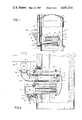
- FIG. 1is a side elevation of a water heater incorporating the heating unit of the invention with parts broken away in section;
- FIG. 2is an enlarged vertical section of the heating unit
- FIG. 3is an end view of the heating unit with parts broken away
- FIG. 4is a section taken along line 4--4 of FIG. 2.
- FIG. 1shows a water heater 1 composed of a generally cylindrical tank 2 which is enclosed by a dome-shaped upper head 3 and a dome-shaped lower head 4.
- the cylindrical tank 2, as well as the heads 3 and 4are preferably formed of corrosion resistant construction, such as glass coated steel.
- An outer jacket 5is spaced outwardly from the tank 2 and upper head 3 and a layer of insulating material 6, which can be a fibrous or a foam-type insulation, is positioned between jacket 5 and tank 2 and head 3.
- Cold water to be heatedis introduced into the lower portion of the tank through an inlet nipple 7, while heated water is withdrawn from the upper end of the tank through an outlet 8.
- water in the tankis heated by a heating unit indicated generally by 9, which is mounted in an opening in the cylindrical tank 2 and is positioned above lower head 4.
- a reinforcing ring 10is welded to an outwardly extending flange 11 that borders an opening in tank 2.
- the heating unit 9includes a mounting plate 12 which is secured to the reinforcing ring 10 through a series of circumferentially spaced fasteners 13.
- Mounted within an opening in mounting plate 12is a tubular member 14 which defines a combustion chamber 15.
- Tubular member 14extends horizontally across tank 2 and the inner end of tubular member 14 is welded within an opening in end plate 16.
- a plurality of heat exchanger tubes 17are positioned generally beneath tubular member 14 and are welded within aligned openings in mounting plate 12 and end plate 16. As best shown in FIGS. 2 and 3, the heat exchanger tubes 17 are disposed in parallel relation and the bundle of tubes extends approximately 180° around the member 14.
- Heating unit 9also includes a generally dome-shaped deflector 18 which is secured to the peripheral edge of end plate 16, and waste gases of combustion from the combustion chamber are directed by the deflector 18 into the heat exchanger tubes 17, as will be hereinafter described.
- Heating unit 9also includes a burner 19 which is mounted within combustion chamber 15.
- Burner 19can have a construction similar to that disclosed in the copending U.S. application Ser. No. 580,686, filed Feb. 15, 1984.
- burner 19includes a cylindrical inner metal screen or support 20 and the outer end of screen 20 is secured to the annular flange 21 of mounting ring 22.
- Mounting ring 22is attached to mounting plate 12 through a series of studs 23.
- the inner end of screen 20is closed off by a closure plate 24, so that a fuel-air mixture entering the end of the burner 19 will flow outwardly through screen 20 and through an outer fabric sleeve 25 which is supported on screen 20.
- the fabric sleeve 25can be made of woven ceramic fabric, similar to that described in the aforementioned U.S. patent application, Ser. No. 580,686.
- the ends of screen 20can be provided with circumferential grooves 26, and tie rings or clamps 27 mate with the grooves 26 to secure the sleeve to the screen.
- the clampsare composed of an inner metal tie located within an outer ceramic fabric ring.
- a fuel-air mixtureis supplied to radiant burner 19 through a tube 28, and the fuel is ignited on the outer surface of burner 19 by a conventional igniter 29 that is mounted within an opening in mounting ring 22.
- One end of the supply tube 28is secured to a flange 30 that extends outwardly from mounting ring 31, and mounting ring 31 is secured flatwise to mounting ring 22 through the studs 23.
- Suitable gasketscan be interposed between the rings 22 and 31, as well as between the ring 22 and the end of the tubular member 14.
- the outer end of tube 28is secured around 32.
- the central portion of restrictor 32is formed with an orifice or opening 33 having a cross-sectional area which is sized to provide the proper air-fuel mixture being fed to burner 19.
- the upper flange 34, of restrictor 32is secured to the undersurface of a blower 35.
- Blower 35is a conventional type and air is discharged from the blower through restrictor 32 and supply tube 28 to the burner 19.
- a fuelsuch as natural or propane gas
- a fuelis supplied to the burner 19, through a gas inlet nipple 36, which is connected to the central portion of supply tube 28, as best shown in FIG. 3.
- the inlet nipple 36is connected to a conventional gas valve. With this constuction, the air being delivered by blower 35 will be mixed with the fuel in the supply tube 28 and the mixture delivered to the burner 19 where the fuel will be ignited on the outer surface of the burner which heats tubular member 14 to thereby heat the water.
- the waste gases of combustion being discharged from the inner end of tubular member 14,will be deflected downwardly by deflector 18 and pass through the bundle of heat exchanger tubes 17 where additional heat will be transferred from hot waste gases to the surrounding water in the tank.
- baffle or turbulatorcan be in each tube 17.
- the turbulatorsincrease the turbulence of the waste gas flowing within the tubes to thereby increase the efficiency of heat transfer.
- Blower 35causes a draft through the radiant burner 19 and heat exchanger tubes 17. It is preferred that the blower be positioned upstream of the radiant burner 19, for in this position it will not be contacted by the highly corrosive waste gases of combustion and can more accurately, in combination with restrictor 32, control the fuel-air ratio for the combustion process.
- a conventional pressure switch 37is mounted in communication with blower 35 and is responsive to a predetermined pressure in the outlet of the blower. If the pressure falls beneath the predetermined setting, indicating that the blower is not operating properly, pressure switch 37 will prevent operation of the gas valve so that fuel will not be introduced into the system.
- a second pressure switch 38can be mounted in the tube 28.
- the region downstream of orifice 33will have a relatively low pressure during normal operation of blower 35.
- Switch 38is adapted to cut off operation of the entire system if the pressure in this region increases beyond a predetermined setting, indicating a blockage downstream in the system.
- Cooling of the waste gases of combustion in heat exchanger tubes 17can generate a substantial quantity of condensation and the latent heat of vaporization will be transferred to the water in the tank to further increase the efficiency of the operation.
- the waste gases and condensate being discharged from tubes 17are collected in a generally U-shaped collector 39 which is attached to the mounting plate 12 and communicates with the outlet or downstream ends of the heat exchanger tubes 17. Tubes 17 slope downwardly toward collector 39.
- a gasket 40is interposed between the edge of the collector and the face of the mounting plate.
- Collector 39is secured to mounting plate 12 by a fasteners 41 which extend through lugs or ears 42 attached to the upper ends of collector 39.
- a bracket 43is mounted to the undersurface of the collector and is secured by fastener 44 to the mounting ring 12.
- the waste gases entering collector 39are discharged through an outlet 45 which connected through flue 46 to the atmosphere.
- a condensate trap 47is mounted within an opening in the lower surface of collector 39.
- the condensate trap 48can be constructed in the manner shown in copending U.S. patent application Ser. No. 616,018, filed June 4, 1984.
- the upper end of the body 48 of trap 47is sealed within an opening bordered by flange 49 on collector 39.
- the lower portion of body 48defines an outlet 50 having a raised seat 51, and a ball 52, having a specific gravity less than water, rests on the seat to close off the outlet 50.
- ball 52When the body 48 fills with condensate, ball 52 will float, opening outlet 50 and enabling the condensate to drain through the outlet to a collection site.
- the condensation trap 47permits the automatic discharge of condensate from the collector 39, but prevents waste gases of combustion from passing through the trap to the atmosphere.
- the water heaterDue to the combination of burner 19 and the heat exchanger, the water heater has a high in-service efficiency, above 90%.
- the air-fuel mixtureis moved through the burner 19 and heat exchanger tubes 17 by a blower, so that the waste gases can be discharged directly to the exterior without the need of a chimney.
- the heating unit 9is located in the tank 1 rather than being positioned beneath the bottom head 4, the buildup of scale on the bottom head, in locations having a high lime content in the water, will not effect the efficiency of the heating unit.
- the entire heating unitis an integral unit, it can be readily disassembled from the heater for repair or replacement, or for cleaning of scale or sediment from the bottom head of the tank.
Landscapes
- Engineering & Computer Science (AREA)
- Chemical & Material Sciences (AREA)
- Combustion & Propulsion (AREA)
- Mechanical Engineering (AREA)
- General Engineering & Computer Science (AREA)
- Physics & Mathematics (AREA)
- Thermal Sciences (AREA)
- Instantaneous Water Boilers, Portable Hot-Water Supply Apparatuses, And Control Of Portable Hot-Water Supply Apparatuses (AREA)
- Heat-Pump Type And Storage Water Heaters (AREA)
- Details Of Fluid Heaters (AREA)
Abstract
Description
Claims (7)
Priority Applications (4)
| Application Number | Priority Date | Filing Date | Title |
|---|---|---|---|
| US06/662,371US4651714A (en) | 1984-10-18 | 1984-10-18 | High efficiency water heater |
| CA000492810ACA1267818A (en) | 1984-10-18 | 1985-10-11 | High efficiency water heater |
| EP85307486AEP0179617A3 (en) | 1984-10-18 | 1985-10-17 | High efficiency water heater |
| JP60234397AJPS61105049A (en) | 1984-10-18 | 1985-10-18 | Water heater |
Applications Claiming Priority (1)
| Application Number | Priority Date | Filing Date | Title |
|---|---|---|---|
| US06/662,371US4651714A (en) | 1984-10-18 | 1984-10-18 | High efficiency water heater |
Publications (1)
| Publication Number | Publication Date |
|---|---|
| US4651714Atrue US4651714A (en) | 1987-03-24 |
Family
ID=24657436
Family Applications (1)
| Application Number | Title | Priority Date | Filing Date |
|---|---|---|---|
| US06/662,371Expired - LifetimeUS4651714A (en) | 1984-10-18 | 1984-10-18 | High efficiency water heater |
Country Status (4)
| Country | Link |
|---|---|
| US (1) | US4651714A (en) |
| EP (1) | EP0179617A3 (en) |
| JP (1) | JPS61105049A (en) |
| CA (1) | CA1267818A (en) |
Cited By (32)
| Publication number | Priority date | Publication date | Assignee | Title |
|---|---|---|---|---|
| US4790268A (en)* | 1985-02-14 | 1988-12-13 | A. O. Smith Corporation | Submersible chamber water heater |
| US4858592A (en)* | 1987-02-20 | 1989-08-22 | Belshaw Bros., Inc. | Burner system |
| US4875465A (en)* | 1988-05-16 | 1989-10-24 | A. O. Smith Corporation | High efficiency submersible chamber water heater |
| US4877014A (en)* | 1988-01-19 | 1989-10-31 | American Standard Inc. | Tube arrangement for heat exchanger |
| US5101806A (en)* | 1987-12-15 | 1992-04-07 | Moffat Appliances Limited | Gas infra-red burner in a heater tube or heat exchanger |
| US5165887A (en)* | 1991-09-23 | 1992-11-24 | Solaronics | Burner element of woven ceramic fiber, and infrared heater for fluid immersion apparatus including the same |
| US5197415A (en)* | 1992-04-02 | 1993-03-30 | Rheem Manufacturing Company | Wet-base, down-fired water heater |
| US5207211A (en)* | 1992-04-02 | 1993-05-04 | Rheem Manufacturing Company | Multiple U-tube down fired water heater |
| US5699756A (en)* | 1996-10-08 | 1997-12-23 | Rheem Manufacturing Co. | Wet-base, down-fired water heater |
| US5809941A (en)* | 1996-04-16 | 1998-09-22 | Allaire; Ernest Lee | High efficiency hot water heater for recreational vehicles |
| US6085738A (en)* | 1993-07-09 | 2000-07-11 | International Thermal Investments Ltd. | Multi-fuel burner and heat exchanger |
| US6564756B1 (en)* | 2002-03-12 | 2003-05-20 | Andre Rayes | Firetube boiler |
| WO2005031222A1 (en)* | 2003-09-26 | 2005-04-07 | E.On Ruhrgas Ag | Tempering device for industrial heat consumers |
| US7032543B1 (en) | 2005-01-12 | 2006-04-25 | Aos Holding Company | Water heater with pressurized combustion |
| US20070051359A1 (en)* | 2005-09-08 | 2007-03-08 | Ozzie Missoum | Looped system fuel-fired fluid heating/storage device |
| US20070051358A1 (en)* | 2005-09-08 | 2007-03-08 | Ozzie Missoum | Single pass fuel-fired fluid heating/storage device |
| US20080066694A1 (en)* | 2006-08-16 | 2008-03-20 | Aos Holding Company | Gas water heater |
| US20090241858A1 (en)* | 2008-04-01 | 2009-10-01 | Aos Holding Company | Water heater with high efficiency baffles |
| US20090308333A1 (en)* | 2008-06-12 | 2009-12-17 | Hughes Dennis R | Removable heat exchanger for a gas fired water heater |
| US20100212602A1 (en)* | 2009-02-25 | 2010-08-26 | Robertshaw Controls Company | Valve Shank Mount Assembly for a Water Heater |
| US20110067685A1 (en)* | 2009-09-23 | 2011-03-24 | Myers Robert L | Gas-Fueled Food Cooker with a Sealed Heating Conduit |
| US20120240869A1 (en)* | 2011-03-25 | 2012-09-27 | Laars Heating Systems Company | Condensing gas appliance and condensate trap therefor |
| US20130019816A1 (en)* | 2011-07-21 | 2013-01-24 | Claude Lesage | Fuel-fired water heater with air draft inducer and flue heat exchanger |
| US20140224191A1 (en)* | 2013-02-12 | 2014-08-14 | Lester James Thiessen | Burner Tube Heat Exchanger for a Storage Tank |
| US20140326197A1 (en)* | 2011-10-10 | 2014-11-06 | Sridhar Deivasigamani | Combined gas-water tube hybrid heat exchanger |
| WO2015168018A1 (en) | 2014-04-28 | 2015-11-05 | Idalex Technologies, Inc. | Heat recovery method and apparatus |
| WO2016179674A1 (en)* | 2015-05-12 | 2016-11-17 | Cordeiro Alcione Mario Costa | Indirect steam air heater with closed condensate circuit and recovery of heat from chimney gases |
| CN106642111A (en)* | 2016-12-16 | 2017-05-10 | 北京神雾环境能源科技集团股份有限公司 | Fractional combustion heat accumulating type radiant tube combustion device |
| US20180195760A1 (en)* | 2017-01-06 | 2018-07-12 | Noritz Corporation | Combustion apparatus and method of manufacturing the same |
| RU2680458C1 (en)* | 2018-03-23 | 2019-02-21 | Валерий Игнатьевич Гуров | Contact water heater |
| US20210366734A1 (en)* | 2019-12-06 | 2021-11-25 | J-Solution Co., Ltd. | Cooling water circulation system-integrated by-product collection apparatus |
| CN116677981A (en)* | 2023-06-21 | 2023-09-01 | 龙正环保股份有限公司 | A natural gas boiler system and working method |
Families Citing this family (7)
| Publication number | Priority date | Publication date | Assignee | Title |
|---|---|---|---|---|
| NL193569C (en)* | 1992-07-09 | 2000-02-02 | Teunis Luigjes | Device for heating a liquid. |
| NO179424C (en)* | 1993-12-06 | 1996-10-02 | Arild Hardeng | Heat storage and method of its commissioning and operation |
| NL1005075C2 (en)* | 1997-01-23 | 1998-08-03 | Besloten Vennootschap Verbakel | Production of heat and carbon dioxide for commercial greenhouse |
| JP2010151384A (en)* | 2008-12-25 | 2010-07-08 | Noritz Corp | Cogeneration system |
| CN102353146A (en)* | 2011-09-02 | 2012-02-15 | 王凯一 | Horizontal boiling heat pipe heating furnace and manufacturing method |
| HK1209100A1 (en) | 2012-05-22 | 2016-03-24 | 基因泰克有限公司 | N-substituted benzamides and their use in the treatment of pain |
| CN106482100B (en)* | 2016-12-16 | 2019-02-01 | 神雾科技集团股份有限公司 | A kind of New Regenerative radiant tube combustion device |
Citations (14)
| Publication number | Priority date | Publication date | Assignee | Title |
|---|---|---|---|---|
| US1974288A (en)* | 1933-11-24 | 1934-09-18 | George W Nigh | Steam boiler |
| US2127445A (en)* | 1935-03-12 | 1938-08-16 | Bailey Meter Co | Control mechanism for furnaces |
| US2146565A (en)* | 1937-04-27 | 1939-02-07 | Curtis Samuel | Boiler |
| US2479042A (en)* | 1943-06-09 | 1949-08-16 | Richard I Gaines | Water heater |
| US3167066A (en)* | 1962-07-12 | 1965-01-26 | Phillips Petroleum Co | Radiant heating |
| US3238928A (en)* | 1964-01-27 | 1966-03-08 | James L Phillips | Boiler |
| US3507481A (en)* | 1968-02-27 | 1970-04-21 | Columbia Gas Syst | Warm air furnace with radiant burner |
| US3823704A (en)* | 1973-02-14 | 1974-07-16 | Rheem International | Power burner application to fin tube heat exchanger |
| US4090476A (en)* | 1975-11-18 | 1978-05-23 | Stav, Praha, Vyrobni Stavebni Druzstvo Stredisko Monta | Method and apparatus for the combustion of gaseous or liquid fuels |
| US4164210A (en)* | 1977-08-30 | 1979-08-14 | Gas Research Institute | Pulse combustion system for heating of air |
| US4275705A (en)* | 1979-03-15 | 1981-06-30 | Canadian Gas Research Institute | Two-stage heat exchanger |
| US4303042A (en)* | 1979-09-24 | 1981-12-01 | Kabushiki Kaisha Taada | Water heater |
| US4314542A (en)* | 1978-08-21 | 1982-02-09 | Slyman Manufacturing Corporation | Infra-red domestic furnace |
| US4425902A (en)* | 1981-04-08 | 1984-01-17 | Gaz De France | Submersible device for heating liquids |
Family Cites Families (4)
| Publication number | Priority date | Publication date | Assignee | Title |
|---|---|---|---|---|
| DE2002922A1 (en)* | 1970-01-23 | 1971-08-12 | Bergfeld & Heider | Water heater |
| JPS5468262U (en)* | 1977-10-25 | 1979-05-15 | ||
| US4220132A (en)* | 1978-12-13 | 1980-09-02 | The Barber Manufacturing Company | Gas-fired radiant burner |
| CA1241910A (en)* | 1984-02-16 | 1988-09-13 | Dirk N. Granberg | Radiant energy burner |
- 1984
- 1984-10-18USUS06/662,371patent/US4651714A/ennot_activeExpired - Lifetime
- 1985
- 1985-10-11CACA000492810Apatent/CA1267818A/ennot_activeExpired - Lifetime
- 1985-10-17EPEP85307486Apatent/EP0179617A3/ennot_activeWithdrawn
- 1985-10-18JPJP60234397Apatent/JPS61105049A/enactivePending
Patent Citations (14)
| Publication number | Priority date | Publication date | Assignee | Title |
|---|---|---|---|---|
| US1974288A (en)* | 1933-11-24 | 1934-09-18 | George W Nigh | Steam boiler |
| US2127445A (en)* | 1935-03-12 | 1938-08-16 | Bailey Meter Co | Control mechanism for furnaces |
| US2146565A (en)* | 1937-04-27 | 1939-02-07 | Curtis Samuel | Boiler |
| US2479042A (en)* | 1943-06-09 | 1949-08-16 | Richard I Gaines | Water heater |
| US3167066A (en)* | 1962-07-12 | 1965-01-26 | Phillips Petroleum Co | Radiant heating |
| US3238928A (en)* | 1964-01-27 | 1966-03-08 | James L Phillips | Boiler |
| US3507481A (en)* | 1968-02-27 | 1970-04-21 | Columbia Gas Syst | Warm air furnace with radiant burner |
| US3823704A (en)* | 1973-02-14 | 1974-07-16 | Rheem International | Power burner application to fin tube heat exchanger |
| US4090476A (en)* | 1975-11-18 | 1978-05-23 | Stav, Praha, Vyrobni Stavebni Druzstvo Stredisko Monta | Method and apparatus for the combustion of gaseous or liquid fuels |
| US4164210A (en)* | 1977-08-30 | 1979-08-14 | Gas Research Institute | Pulse combustion system for heating of air |
| US4314542A (en)* | 1978-08-21 | 1982-02-09 | Slyman Manufacturing Corporation | Infra-red domestic furnace |
| US4275705A (en)* | 1979-03-15 | 1981-06-30 | Canadian Gas Research Institute | Two-stage heat exchanger |
| US4303042A (en)* | 1979-09-24 | 1981-12-01 | Kabushiki Kaisha Taada | Water heater |
| US4425902A (en)* | 1981-04-08 | 1984-01-17 | Gaz De France | Submersible device for heating liquids |
Cited By (42)
| Publication number | Priority date | Publication date | Assignee | Title |
|---|---|---|---|---|
| US4790268A (en)* | 1985-02-14 | 1988-12-13 | A. O. Smith Corporation | Submersible chamber water heater |
| US4858592A (en)* | 1987-02-20 | 1989-08-22 | Belshaw Bros., Inc. | Burner system |
| US5101806A (en)* | 1987-12-15 | 1992-04-07 | Moffat Appliances Limited | Gas infra-red burner in a heater tube or heat exchanger |
| US4877014A (en)* | 1988-01-19 | 1989-10-31 | American Standard Inc. | Tube arrangement for heat exchanger |
| US4875465A (en)* | 1988-05-16 | 1989-10-24 | A. O. Smith Corporation | High efficiency submersible chamber water heater |
| US5165887A (en)* | 1991-09-23 | 1992-11-24 | Solaronics | Burner element of woven ceramic fiber, and infrared heater for fluid immersion apparatus including the same |
| US5197415A (en)* | 1992-04-02 | 1993-03-30 | Rheem Manufacturing Company | Wet-base, down-fired water heater |
| US5207211A (en)* | 1992-04-02 | 1993-05-04 | Rheem Manufacturing Company | Multiple U-tube down fired water heater |
| US6085738A (en)* | 1993-07-09 | 2000-07-11 | International Thermal Investments Ltd. | Multi-fuel burner and heat exchanger |
| US5809941A (en)* | 1996-04-16 | 1998-09-22 | Allaire; Ernest Lee | High efficiency hot water heater for recreational vehicles |
| US5699756A (en)* | 1996-10-08 | 1997-12-23 | Rheem Manufacturing Co. | Wet-base, down-fired water heater |
| US6564756B1 (en)* | 2002-03-12 | 2003-05-20 | Andre Rayes | Firetube boiler |
| WO2005031222A1 (en)* | 2003-09-26 | 2005-04-07 | E.On Ruhrgas Ag | Tempering device for industrial heat consumers |
| US7032543B1 (en) | 2005-01-12 | 2006-04-25 | Aos Holding Company | Water heater with pressurized combustion |
| US20060150925A1 (en)* | 2005-01-12 | 2006-07-13 | Aos Holding Company | Water heater with pressurized combustion |
| US7513221B2 (en) | 2005-01-12 | 2009-04-07 | Aos Holding Company | Water heater with pressurized combustion |
| US20070051359A1 (en)* | 2005-09-08 | 2007-03-08 | Ozzie Missoum | Looped system fuel-fired fluid heating/storage device |
| US20070051358A1 (en)* | 2005-09-08 | 2007-03-08 | Ozzie Missoum | Single pass fuel-fired fluid heating/storage device |
| US7415943B2 (en) | 2005-09-08 | 2008-08-26 | Rheem Manufacturing Company | Single pass fuel-fired fluid heating/storage device |
| US7634977B2 (en) | 2006-08-16 | 2009-12-22 | Aos Holding Company | Gas water heater |
| US20080066694A1 (en)* | 2006-08-16 | 2008-03-20 | Aos Holding Company | Gas water heater |
| US20090241858A1 (en)* | 2008-04-01 | 2009-10-01 | Aos Holding Company | Water heater with high efficiency baffles |
| US8047164B2 (en)* | 2008-06-12 | 2011-11-01 | Aos Holding Company | Removable heat exchanger for a gas fired water heater |
| US20090308333A1 (en)* | 2008-06-12 | 2009-12-17 | Hughes Dennis R | Removable heat exchanger for a gas fired water heater |
| US20100212602A1 (en)* | 2009-02-25 | 2010-08-26 | Robertshaw Controls Company | Valve Shank Mount Assembly for a Water Heater |
| US8776733B2 (en) | 2009-02-25 | 2014-07-15 | Robertshaw Controls Company | Valve shank mount assembly for a water heater |
| US20110067685A1 (en)* | 2009-09-23 | 2011-03-24 | Myers Robert L | Gas-Fueled Food Cooker with a Sealed Heating Conduit |
| US20120240869A1 (en)* | 2011-03-25 | 2012-09-27 | Laars Heating Systems Company | Condensing gas appliance and condensate trap therefor |
| US8931438B2 (en)* | 2011-03-25 | 2015-01-13 | Laars Heating Systems Company | Condensing gas appliance and condensate trap therefor |
| US20130019816A1 (en)* | 2011-07-21 | 2013-01-24 | Claude Lesage | Fuel-fired water heater with air draft inducer and flue heat exchanger |
| US9546798B2 (en)* | 2011-10-10 | 2017-01-17 | Intellihot Green Technologies, Inc. | Combined gas-water tube hybrid heat exchanger |
| US20140326197A1 (en)* | 2011-10-10 | 2014-11-06 | Sridhar Deivasigamani | Combined gas-water tube hybrid heat exchanger |
| US20140224191A1 (en)* | 2013-02-12 | 2014-08-14 | Lester James Thiessen | Burner Tube Heat Exchanger for a Storage Tank |
| US10773880B2 (en)* | 2013-02-12 | 2020-09-15 | Viro Rentals, Inc. | Burner tube heat exchanger for a storage tank |
| WO2015168018A1 (en) | 2014-04-28 | 2015-11-05 | Idalex Technologies, Inc. | Heat recovery method and apparatus |
| WO2016179674A1 (en)* | 2015-05-12 | 2016-11-17 | Cordeiro Alcione Mario Costa | Indirect steam air heater with closed condensate circuit and recovery of heat from chimney gases |
| CN106642111A (en)* | 2016-12-16 | 2017-05-10 | 北京神雾环境能源科技集团股份有限公司 | Fractional combustion heat accumulating type radiant tube combustion device |
| US20180195760A1 (en)* | 2017-01-06 | 2018-07-12 | Noritz Corporation | Combustion apparatus and method of manufacturing the same |
| RU2680458C1 (en)* | 2018-03-23 | 2019-02-21 | Валерий Игнатьевич Гуров | Contact water heater |
| US20210366734A1 (en)* | 2019-12-06 | 2021-11-25 | J-Solution Co., Ltd. | Cooling water circulation system-integrated by-product collection apparatus |
| US11955351B2 (en)* | 2019-12-06 | 2024-04-09 | J-Solution Co., Ltd. | Cooling water circulation system-integrated by-product collection apparatus |
| CN116677981A (en)* | 2023-06-21 | 2023-09-01 | 龙正环保股份有限公司 | A natural gas boiler system and working method |
Also Published As
| Publication number | Publication date |
|---|---|
| CA1267818A (en) | 1990-04-17 |
| EP0179617A3 (en) | 1987-08-19 |
| EP0179617A2 (en) | 1986-04-30 |
| JPS61105049A (en) | 1986-05-23 |
Similar Documents
| Publication | Publication Date | Title |
|---|---|---|
| US4651714A (en) | High efficiency water heater | |
| US4790268A (en) | Submersible chamber water heater | |
| EP0239189B1 (en) | Gas water heater/boiler and burner therefor | |
| US4793800A (en) | Gas water heater/boiler | |
| US4510890A (en) | Infrared water heater | |
| CA2021763C (en) | Burner for forced draft controlled mixture heating system using a closed combustion chamber | |
| US4875465A (en) | High efficiency submersible chamber water heater | |
| US4742800A (en) | Submersible chamber water heater | |
| US4685425A (en) | Submersible chamber water heater | |
| TW200400337A (en) | High efficiency water heater | |
| AU700861B2 (en) | Water heater with co-located flue inlet and outlet | |
| US20100313827A1 (en) | High-Efficiency Gas-Fired Forced-Draft Condensing Hot Water Boiler | |
| US4275687A (en) | Preheating unit for domestic hot water supply | |
| US5305954A (en) | Heating systems | |
| US3492972A (en) | Hot water heater | |
| EP0354188B1 (en) | Pulse combuster and process | |
| US7500454B2 (en) | High efficiency water heater | |
| US4416254A (en) | Flue structure for domestic heating equipment | |
| US20040139929A1 (en) | Dual function high efficiency water heater | |
| US2335918A (en) | Water heater | |
| US2549755A (en) | Burner base for hot-water tanks | |
| US4884963A (en) | Pulse combustor | |
| US4919120A (en) | Radiant-type heater | |
| US4332236A (en) | Fireplace heat exchanger | |
| GB2063451A (en) | Heater |
Legal Events
| Date | Code | Title | Description |
|---|---|---|---|
| AS | Assignment | Owner name:A.O. SMITH CORPORATION MILWAUKEE, WISCONSIN A CORP Free format text:ASSIGNMENT OF ASSIGNORS INTEREST.;ASSIGNOR:GRANBERG, DIRK N.;REEL/FRAME:004330/0397 Effective date:19840928 | |
| STCF | Information on status: patent grant | Free format text:PATENTED CASE | |
| CC | Certificate of correction | ||
| FEPP | Fee payment procedure | Free format text:PAYMENT IS IN EXCESS OF AMOUNT REQUIRED. REFUND SCHEDULED (ORIGINAL EVENT CODE: F169); ENTITY STATUS OF PATENT OWNER: LARGE ENTITY | |
| REFU | Refund | Free format text:REFUND - PAYMENT OF MAINTENANCE FEE, 4TH YEAR, PL 97-247 (ORIGINAL EVENT CODE: R173); ENTITY STATUS OF PATENT OWNER: LARGE ENTITY Free format text:REFUND - SURCHARGE FOR LATE PAYMENT, PL 97-247 (ORIGINAL EVENT CODE: R177); ENTITY STATUS OF PATENT OWNER: LARGE ENTITY | |
| AS | Assignment | Owner name:AOS HOLDING COMPANY, DELAWARE Free format text:ASSIGNMENT OF ASSIGNORS INTEREST.;ASSIGNOR:A. O. SMITH CORPORATION, A CORP. OF DE;REEL/FRAME:005253/0894 Effective date:19891211 | |
| REMI | Maintenance fee reminder mailed | ||
| FPAY | Fee payment | Year of fee payment:4 | |
| SULP | Surcharge for late payment | ||
| FEPP | Fee payment procedure | Free format text:PAYOR NUMBER ASSIGNED (ORIGINAL EVENT CODE: ASPN); ENTITY STATUS OF PATENT OWNER: LARGE ENTITY | |
| FPAY | Fee payment | Year of fee payment:8 | |
| FPAY | Fee payment | Year of fee payment:12 |