US4650469A - Drug delivery system - Google Patents
Drug delivery systemDownload PDFInfo
- Publication number
- US4650469A US4650469AUS06/769,879US76987985AUS4650469AUS 4650469 AUS4650469 AUS 4650469AUS 76987985 AUS76987985 AUS 76987985AUS 4650469 AUS4650469 AUS 4650469A
- Authority
- US
- United States
- Prior art keywords
- drug
- chassis
- pressure plate
- control module
- combination
- Prior art date
- Legal status (The legal status is an assumption and is not a legal conclusion. Google has not performed a legal analysis and makes no representation as to the accuracy of the status listed.)
- Expired - Lifetime
Links
- 238000012377drug deliveryMethods0.000titleclaimsdescription63
- 239000003814drugSubstances0.000claimsabstractdescription105
- 229940079593drugDrugs0.000claimsabstractdescription88
- 230000007246mechanismEffects0.000claimsabstractdescription53
- 238000010276constructionMethods0.000claimsabstractdescription11
- 238000012423maintenanceMethods0.000claimsabstractdescription11
- 238000004891communicationMethods0.000claimsdescription34
- 238000007789sealingMethods0.000claimsdescription11
- 238000003860storageMethods0.000claimsdescription11
- 230000003993interactionEffects0.000claimsdescription10
- XLYOFNOQVPJJNP-UHFFFAOYSA-NwaterSubstancesOXLYOFNOQVPJJNP-UHFFFAOYSA-N0.000claimsdescription5
- 239000000463materialSubstances0.000claimsdescription4
- 239000006260foamSubstances0.000claimsdescription2
- 238000005086pumpingMethods0.000abstractdescription42
- 238000001802infusionMethods0.000description19
- 230000000295complement effectEffects0.000description11
- 238000004519manufacturing processMethods0.000description8
- 239000012530fluidSubstances0.000description7
- 239000007788liquidSubstances0.000description6
- 210000005069earsAnatomy0.000description4
- 230000001225therapeutic effectEffects0.000description4
- 238000013459approachMethods0.000description3
- 239000008280bloodSubstances0.000description3
- 210000004369bloodAnatomy0.000description3
- 230000006835compressionEffects0.000description3
- 238000007906compressionMethods0.000description3
- 238000000034methodMethods0.000description3
- 238000000926separation methodMethods0.000description3
- 238000011282treatmentMethods0.000description3
- 238000004873anchoringMethods0.000description2
- 230000008859changeEffects0.000description2
- 239000000356contaminantSubstances0.000description2
- 230000000881depressing effectEffects0.000description2
- 238000013461designMethods0.000description2
- 239000000428dustSubstances0.000description2
- 230000036541healthEffects0.000description2
- 238000002347injectionMethods0.000description2
- 239000007924injectionSubstances0.000description2
- 238000001990intravenous administrationMethods0.000description2
- 238000002642intravenous therapyMethods0.000description2
- 239000004973liquid crystal related substanceSubstances0.000description2
- 230000003287optical effectEffects0.000description2
- 238000003825pressingMethods0.000description2
- 208000017667Chronic DiseaseDiseases0.000description1
- 208000007536ThrombosisDiseases0.000description1
- 230000009471actionEffects0.000description1
- 230000003213activating effectEffects0.000description1
- 230000004913activationEffects0.000description1
- 230000001154acute effectEffects0.000description1
- 239000000853adhesiveSubstances0.000description1
- 230000001070adhesive effectEffects0.000description1
- 230000015572biosynthetic processEffects0.000description1
- 239000000599controlled substanceSubstances0.000description1
- 238000007796conventional methodMethods0.000description1
- 238000005336crackingMethods0.000description1
- 230000007812deficiencyEffects0.000description1
- 230000002950deficientEffects0.000description1
- 230000000593degrading effectEffects0.000description1
- 230000000994depressogenic effectEffects0.000description1
- 230000001627detrimental effectEffects0.000description1
- 230000005484gravityEffects0.000description1
- 230000000977initiatory effectEffects0.000description1
- 238000002483medicationMethods0.000description1
- 230000002572peristaltic effectEffects0.000description1
- 229920003023plasticPolymers0.000description1
- 230000037452primingEffects0.000description1
- 238000011084recoveryMethods0.000description1
- 230000009467reductionEffects0.000description1
- 210000002966serumAnatomy0.000description1
- 229920002379silicone rubberPolymers0.000description1
- 239000007787solidSubstances0.000description1
- 239000002904solventSubstances0.000description1
- 230000002195synergetic effectEffects0.000description1
- 231100000331toxicToxicity0.000description1
- 230000002588toxic effectEffects0.000description1
- 125000000391vinyl groupChemical group[H]C([*])=C([H])[H]0.000description1
- 229920002554vinyl polymerPolymers0.000description1
- 230000000007visual effectEffects0.000description1
Images


Classifications
- A—HUMAN NECESSITIES
- A61—MEDICAL OR VETERINARY SCIENCE; HYGIENE
- A61M—DEVICES FOR INTRODUCING MEDIA INTO, OR ONTO, THE BODY; DEVICES FOR TRANSDUCING BODY MEDIA OR FOR TAKING MEDIA FROM THE BODY; DEVICES FOR PRODUCING OR ENDING SLEEP OR STUPOR
- A61M5/00—Devices for bringing media into the body in a subcutaneous, intra-vascular or intramuscular way; Accessories therefor, e.g. filling or cleaning devices, arm-rests
- A61M5/14—Infusion devices, e.g. infusing by gravity; Blood infusion; Accessories therefor
- A61M5/142—Pressure infusion, e.g. using pumps
- A61M5/145—Pressure infusion, e.g. using pumps using pressurised reservoirs, e.g. pressurised by means of pistons
- A61M5/1452—Pressure infusion, e.g. using pumps using pressurised reservoirs, e.g. pressurised by means of pistons pressurised by means of pistons
- A61M2005/14533—Pressure infusion, e.g. using pumps using pressurised reservoirs, e.g. pressurised by means of pistons pressurised by means of pistons cam actuated
- A—HUMAN NECESSITIES
- A61—MEDICAL OR VETERINARY SCIENCE; HYGIENE
- A61M—DEVICES FOR INTRODUCING MEDIA INTO, OR ONTO, THE BODY; DEVICES FOR TRANSDUCING BODY MEDIA OR FOR TAKING MEDIA FROM THE BODY; DEVICES FOR PRODUCING OR ENDING SLEEP OR STUPOR
- A61M2205/00—General characteristics of the apparatus
- A61M2205/12—General characteristics of the apparatus with interchangeable cassettes forming partially or totally the fluid circuit
- A61M2205/128—General characteristics of the apparatus with interchangeable cassettes forming partially or totally the fluid circuit with incorporated valves
Definitions
- the present inventionrelates generally to the delivery of drugs to patients, particularly to systems for providing drug delivery, and specifically, to systems for providing continuous drug delivery.
- Certain drugsrarely achieve their maximum therapeutic action through conventional injection techniques.
- the therapeutic activity of such a drugis improved considerably when it is delivered at controlled rates to maintain optimum drug concentration for a specific period.
- a greater dosage than necessarymust be administered to keep the drug concentration within the effective therapeutic margin for the minimum period needed for treatment.
- the drugcan be given at a precise rate that will keep the drug serum concentration within the therapeutic margin and out of the toxic range.
- Continuous drug deliveryis assuming an ever increasing role in the treatment of acute and chronic illnesses. Many drugs reach their full potential only through precise delivery over an extended period of time.
- the present inventionsolves this and other needs by providing, in the preferred embodiment, a system for delivering a drug to a patient of a modular construction and including control and reservoir modules.
- the reservoir moduleis removably secured to the control module.
- the reservoir moduleincludes a drug container and a member which allows passage of the drug from the container to the patient.
- the control moduleincludes a member for forcing the passage of the drug from the container to the patient.
- the drug forcing member of the control moduleinteracts with the drug passage member of the reservoir module for purposes of delivering a drug stored in the drug container to the patient at desired rates.
- the drug delivery system of the present inventioncan be secured to the patient and allows the patient to be ambulatory.
- the systemincludes an occlusion detector which interrupts the drug forcing member in the event of reduced fluid pressure in the drug passage member to the patient.
- the occlusion detectorincludes a switch attached to the control module which engages, interacts, and is activated by the drug passage member of the reservoir module.
- FIG. 1shows a perspective view of an ambulatory drug delivery system constructed according to the preferred embodiment of the present invention.
- FIG. 2shows a partial, cross sectional view of the ambulatory drug delivery system of FIG. 1 according to section line 2--2 of FIG. 1, with the reservoir module shown in its separated position in phantom.
- FIG. 3shows a top view of the ambulatory drug delivery system of FIG. 1 according to view line 3--3 of FIG. 2.
- FIG. 4shows a partial, cross sectional view of the ambulatory drug delivery system of FIG. 1 according to section line 4--4 of FIG. 2.
- FIG. 5shows an exploded perspective view of the locking mechanism of the ambulatory drug delivery system of FIG. 1.
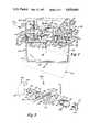
- FIG. 6shows a partial, top view of the control module of an alternate embodiment of an ambulatory drug delivery system according to the teachings of the present invention, with the switch of the occlusion detector being removed.
- FIG. 7shows a partial, sectional view of the ambulatory drug delivery system of FIG. 6 according to section line 7--7 of FIG. 6, with the switch of occlusion detector being exploded therefrom.
- FIG. 8shows a partial, sectional view of the ambulatory drug delivery system of FIG. 6.
- System 10is particularly adapted for securement to a patient such as by a belt allowing the patient to be ambulatory while having continuous infusion of a drug at the desired rate.
- System 10 in its most general preferred formincludes a control module 12 and a reservoir module 14.
- reservoir module 14in its most preferred form includes a reservoir casing 16, a medicament container 18 shown in its most preferred form as a heat sealed vinyl bag, and a pressure plate 20. Bag 18 further includes a member 22 for providing communication between bag 18 and an infusion catheter of the patient and is shown in its most preferred form as an elastomeric tube.
- casing 16is tub shaped and includes a generally closed bottom 24, a generally open top 26, and generally closed sidewalls 28-31.
- Pressure plate 20 in the preferred embodiment showngenerally includes a flat portion 32 having a shape complementary to and for receipt in open top 26 of casing 16.
- Pressure plate 20 in its most preferred formincludes hooked portions 34 which upstand from flat portion 32 at a first end thereof.
- pressure plate 20further includes an inverted U-shaped member 36 upstanding from flat portion 32 at its end opposite to hooked portions 34.
- member 36includes first and second legs 37 and 38 having their first ends connected to flat portion 32 and their second ends connected to a central portion 39 which is generally parallel to flat portion 32.
- Pressure plate 20 in the preferred embodiment shownfurther includes standoffs 40-43 upstanding from the top surface of flat portion 32 to a height for purposes set forth hereinafter.
- Standoffs 40-43generally include first and second portions which extend between the sides of flat portion 32 and which are separated by a distance generally equal to the diameter of tube 22.
- Pressure plate 20 in the preferred embodiment shownfurther includes a trough portion 44 located between standoff 40 and the first end of plate 20 including hooked portions 34 having a size and shape complementary to and for receiving tube 22.
- tube 22extends through an opening 46 formed in flat portion 32 adjacent member 36, extends between the first and second portions of standoffs 40-43, extends through trough portion 44, and through a removed portion 48 formed in the end of flat portion 32 adjacent hooked portions 34.
- tube 22lies on flat portion 32 of pressure plate 20 generally midway between and parallel to the sides of flat portion 32.
- Tube 22 in the preferred embodiment of the present inventionis secured to pressure plate 20 by a solvent bond located between tube 22 and trough portion 44 and is anchored by its other end to pressure plate 20 and reservoir module 14 by its securement to bag 18 captured between pressure plate 20 and casing 16 and its passage through opening 46 of pressure plate 20.
- control module 12in its most preferred form includes a casing 50 shown in its most preferred form formed of first and second halves and includes a generally closed top 52, a generally open bottom 54, and generally closed sidewalls 56-59.
- Control module 12further includes a member 62 interacting with tube 22 for forcing liquid from bag 18 through tube 22 and for preventing free flow of liquid through tube 22 either to or from bag 18.
- Member 62is shown in its most preferred form as a pumping mechanism.
- Pumping mechanism 62includes a chassis 64 including a first flat portion 66 and a second flat portion 68 generally at right angles to each other.
- flat portion 68has a shorter length than portion 66 and the ends of flat portion 68 are both spaced from the respective ends of portion 66.
- Chassis 64further includes braces 70 and 72 which extend between portion 66 and the ends of portion 68 and which are spaced from each other and the ends of portion 66.
- Pumping mechanism 62further includes in its most preferred form a camshaft 74 rotatably mounted between braces 70 and 72 and having a first cam portion 76 located between second and third cam portions 78 and 80 on shaft 74.
- Shaft 74extends through brace 70 and further includes a driven gear 82 and an optical switch indicator 84 shown in its most preferred form as a flag located between the end of portion 66 and brace 70.
- pumping mechanism 62further includes an expulsor 86 which is slideably mounted in an aperture 88 formed in portion 66.
- Expulsor 86includes a head portion 92 including an arcuate portion 94 for engaging with cam portion 76 and an abutment surface 96 which prevents expulsor 86 from passing through aperture 88 of chassis 64.
- pumping mechanism 62further includes first and second valves 100 and 102 which are slideably mounted in apertures 104 and 106 formed in portion 66 of chassis 64, respectively.
- Valves 100 and 102each include a head portion 110 having an arcuate portion 112 for engaging with cam portions 78 and 80 and having an abutment surface 114 which prevents valves 100 and 102 from passing through apertures 104 and 106 of chassis 64.
- Provisions 90are further provided for biasing expulsor 86 and valves 100 and 102 towards cam portions 76, 78, and 80 and for sealing expulsor 86 and valves 100 and 102 with flat portion 66 of chassis 64 of control module 12.
- provisions 90is a closed cell foam gasket located in a cavity 98 formed in the top surface of flat portion 66 of chassis 64 and with which head portions 92 and 100 of expulsor 86 and valves 110 and 102 abut.
- Gasket 90includes apertures 108 formed therein corresponding to apertures 88, 104, and 106 of chassis 64 and having a size and shape complementary to the receipt of expulsor 86 and valves 100 and 102.
- Gasket 90has sufficient resiliency to bias expulsor 86 and valves 100 and 102 and has sufficient sealing ability to seal between chassis 64 and expulsor 86 and valves 100 and 102.
- pumping mechanism 62further includes a member 118 for driving camshaft 74 shown as a motor mounted between braces 70 and 72.
- Motor 118includes a drive shaft 120 which extends through brace 70 having a drive gear 122 in gearing relation with gear 82 of camshaft 74.
- motor 118is a D.C. motor that rotates camshaft 74 through 360 degrees and then stops, with the number of rotations of shaft 74 controlling the volume of medicament being pumped from bag 18 of reservoir module 14.
- flat portion 66 of chassis 64includes an upraised portion 124 located adjacent its first end having depending ears 126 extending therefrom. Hinge pins 128 are further provided extending between ears 126 generally parallel to flat portion 66. Hinge pins 128 are complementary to and for hingedly receiving hooked portions 34 of plate 20 of reservoir module 14.
- Flat portion 66 of chassis 64further includes an aperture 130 located adjacent its opposite end complementary to and for receiving U-shaped member 36 of plate 20 of reservoir module 14.
- Control module 12further includes a source of power for motor 118, such as a battery, and suitable electronic controls for the operation of motor 118 for controlling the pumping of the liquid from bag 18 through tube 22. Included with the electronic controls, control module 12 may include a liquid crystal display (LCD) 132 and switches or keys, generally designated 134, for purposes of programming the electronic controls to start or stop the pump, to vary the rate of pumping, for priming the pump, to limit patient operation of the pump, and like functions.
- LCDliquid crystal display
- programming modes of system 10 of the present inventionmay include: delivering drug concentrations of different rates; delivering a basal infusion at a set rate; allowing the patient the option of varying the basal rate up to the maximum rate allowed by the physician; delivering an incremental bolus dose at a set rate; allowing the patient the option of varying the incremental dose up to the maximum rate allowed by the physician; allowing the physician to set the minimum time between incremental doses; allowing the physician to limit the number of incremental doses per hour; and displaying the milligrams of medicament delivered, the number of incremental doses delivered, and the amount of volume of medicament remaining in the reservoir on the LCD 132.
- LCD 132visually indicates various conditions of system 10 such as the rate of pumping, the volume of liquid remaining in bag 18, and like conditions.
- LCD 132 and keys 134are located in sidewall 56 of casing 50 of control module 12.
- the electronic controlsmay further include a user interaction signal such as a buzzer or other audible alarm for purposes of indicating the condition of system 10 such as indicating the pressing of keys 134, a low battery, an empty reservoir, an error in programming the electronic controls, or like condition.
- a manufacturer of a system according to the present inventionwould be in a position to program each system by modern electronics. That is, taking into account the above factors and other factors and constraints set by modern medicine and the laws of physics, a manufacturer can program each system to receive such variables as: patient dosage; medicament concentration; the medication schedule; the reservoir size; and other like considerations and can arrange the system to perform such functions as: dosage control; frequency of medication; variation of medication scheduling and dosage; various warnings and conditions, such as a low battery, error in programming the electronic controls, pressing of keys 134, and an empty reservoir; residential reservoir medication amount; and other like functions for particular medications, particular patients, particular needs, etc.
- casing 50further includes an L-shaped casing portion 136 extending from sidewall 57 and between sidewalls 56 and 58.
- portion 136includes a first leg 138 having a first end integrally connected to sidewall 57 and having a second end integrally connected to a second leg 140. The free end of leg 140 extends into open bottom 54 of casing 50.
- flat portion 66 of chassis 64has a shape and size complementary to and for receipt in open bottom 54 of casing 50.
- Control module 12further includes sealing members 142 located between the ends and sides of portion 66 of chassis 64 and sidewalls 56-69 of casing 50. Further, sealing member 144 is located between the free end of leg 140 of L-shaped casing portion 136 and the top surface of flat portion 66 of chassis 64.
- a substantially water tight compartmentwhich includes motor 118, the electronic controls, the pumping mechanism 62, and other system components is defined by sidewalls 56-59, top 52, and L-shaped casing portion 136 of casing 50, flat portion 66 of chassis 64, expulsor 86, valves 100 and 102, gasket 90, and sealing members 142 and 144.
- the system components within this water tight compartmentare protected from dust, the elements, or other contaminants which may produce damage thereto.
- System 10 in the preferred embodimentincludes provisions 146 for removably holding the reservoir module 14 to the control module 12 and is shown in its most preferred form as a locking mechanism.
- mechanism 146generally includes, in the preferred embodiment, a latch guide 148, a latch button 150, a locking bolt 152, a pin 154, and a spring 156.
- Latch guide 148generally includes a flat portion 158 which is captured between the halves of casing 50.
- a cylindrical member 160is further provided depending from the end of flat portion 158 for rotatably and slideably receiving latch button 150.
- Ears 162are provided on cylindrical member 160 for capturing between the halves of casing 50.
- a longitudinally extending, arcuate portion 164is further provided on latch guide 148 depending from flat portion 158 and having a first end secured to cylindrical member 160.
- the second, free end of arcuate portion 164includes a helical, camming portion 166 having stops 168 and 170 formed in and by arcuate portion 164.
- Camming portion 166further includes a detent 172 formed adjacent stop 170 at the longitudinally inward end of camming portion 166.
- Latch button 150generally includes a shank portion 174 which is rotatably and slideably received in cylindrical member 160 of latch guide 148 about its longitudinal axis and a head portion 176 which prevents shank portion 174 from passing through cylindrical member 160 in a first direction.
- Latch button 150further includes an eccentric portion 178 which is eccentrically located with respect to the longitudinal axis of shank portion 174 and an extended shank portion 180.
- Locking bolt 152generally includes a cylindrical portion 182 having a shape and size complementary to and for receipt on eccentric portion 176 of latch button 150.
- Locking bolt 152further generally includes a T-shaped member 184 extending from cylindrical portion 182.
- T-shaped member 184generally includes a leg member 185 having its first end connected to cylindrical portion 182 and its second end connected substantially to the middle of a cross member 186.
- Cross member 186includes a first inner end 187 and a second, outer end 188.
- Cross member 186includes a surface 189 located on the upper surface of cross member 186 between leg member 185 and end 187 for engaging with central portion 39 of U-shaped member 36 of pressure plate 20.
- Locking bolt 152is held on eccentric portion 178 of latch button 150 in the preferred embodiment of the present invention between a shoulder formed between shank portion 174 and eccentric portion 178 and pin 154 extending through the extended shank portion 180 of latch button 150.
- Pin 154further acts as the follower for camming portion 166 and for detent 172 of arcuate portion 164 of latch guide 148. Pin 154 also prevents shank portions 174 and 180 and eccentric portion 178 from passing through cylindrical member 160 in the opposite direction of head portion 176.
- pin 154when latch button 150 is located at its first, extreme outward, unlocked position, pin 154 abuts with camming portion 166 adjacent stop 168 and end 188 of T-shaped member 184 of locking bolt 152 abuts with cylindrical member 160 of latch guide 148. Pin 154 further acts as an abutment for spring 158, with the spring 158 located concentrically on latch button 150 and extending between leg 140 of L-shaped casing portion 136 and pin 154. Thus, spring 158 biases latch button 150 in an outward direction.
- Locking mechanism 146further includes provisions 190 for allowing the longitudinal movement of locking bolt 152 but preventing rotatable movement of locking bolt 152 with latch button 150. Provisions 190 are shown in the preferred embodiment of the present invention as tracks formed in the top surface of flat portion 66 of chassis 64 intermediate aperture 130 and its second end and having a shape complementary to and for slideable receipt of cross member 186 of T-shaped member 184 of locking bolt 152.
- Suitable provisions 191 for rotating latch button 150may further be provided for locking mechanism 146.
- provisions 191include a cavity 192 formed in head portion 176 of latch button 150 having a concentrically located, upstanding post 193.
- cavity 192has a multisided perimeter, such as a hexagonal cross section and post 193 has a shape such as a circular cross section.
- Provisions 191further includes a key 194 having a lug end 196 having a shape complementary to and for receipt within cavity 192, with the end 196 having a cavity 198 located generally concentrically therein.
- Cavity 198has a size and shape complementary to and for receipt on post 193.
- locking mechanism 146 utilizing key 194restricts the personnel who can unlock reservoir module 14 from control module 12. Specifically, keys 194 would be given only to physicians, pharmacists, and other authorized persons and not be given to patients utilizing system 10 or other unauthorized persons. Thus, without keys 194, the patients would be unable to rotate latch button 150 and release locking mechanism 146.
- provisions 191may include an arcuate cavity formed in head portion 176 of latch button 150 for receiving the edge of a coin or similar object. Thus, by turning the coin, latch button 150 may be rotated.
- provisions 191may take other forms according to the present invention.
- locking mechanism 146can now be set forth and appreciated. For the sake of example, it will be assumed that U-shaped member 136 of pressure plate 20 is extending through aperture 130 of flat portion 66 of chassis 64 and latch button 150 is in its outward, unlocked position. To lock locking mechanism 146, latch button 150 may be pressed from its first position inwardly within latch guide 148 against the bias of spring 156 towards its second position. When latch button 150 is moved inwardly, locking bolt 152 secured thereto by pin 154 also moves inwardly, with surface 189 of cross member 186 of locking bolt 152 being located under the central portion 39 of U-shaped member 36 of pressure plate 20. At that time, latch button 150 may be rotated to its third position utilizing provisions 191.
- latch button 150Due to the eccentric interaction between locking bolt 152 and latch button 150, rotation of latch button 150 causes locking bolt 152 to raise up engaging surface 189 with central portion 39. It should be noted that tracks 190 of chassis 64 prevent locking bolt 152 from rotating with latch button 150. Latch button 150 may be rotated until pin 154 abuts with stop 170 and is located within detent 172 of camming portion 166. At that time, due to its eccentric interaction, locking bolt 152 exerts an upward, locking force on central portion 39 of pressure plate 20. To enhance this exertion of an upward force, surface 189 and central portion 39 may include complementary, wedge-like tapers as in the most preferred form of the present invention. Further, with pin 154 located in detent 172, latch button 150 is prevented from accidentally rotating from its third, inward, locked position.
- latch button 150is not located in its third position such that pin 154 is not located in detent 172, pin 154 under the bias of spring 156 will ride back upon camming portion 166 until stop 168.
- latch button 150 to which pin 154 is securedrotates and slides back to its first, unlocked position such that locking bolt 152 does not engage with U-shaped member 36.
- reservoir module 14is not secured to control module 12. The reason for this subtle feature is to insure that partial engagement of locking bolt 152 with U-shaped member 36 does not occur.
- reservoir module 14may be positioned in a first position with respect to control module 12 such that hooked portions 34 of pressure plate 20 engage with hinge pins 128 of chassis 64 of control module 12.
- reservoir module 14is separable from the control module 12.
- Reservoir and control modules 12 and 14may then be moved towards their second position such that hooked portions 34 of pressure plate 20 hook on hinge pins 128 of chassis 64 of control module 12.
- control module 12 and reservoir module 14may be placed on a flat surface such that bottom 24 of casing 16 of reservoir module 14 rests upon the flat surface.
- Control module 12may then be pressed firmly in its second position such that U-shaped member 136 of pressure plate 20 of reservoir module 14 extends through aperture 130 of chassis 64 of control module 12 as shown in solid in FIG. 2.
- Locking mechanism 146may then be locked by sliding and rotating latch button 150 in a manner set forth hereinbefore such that locking bolt 152 engages with and raises up central portion 39 of pressure plate 20.
- pin 154is located within detent 172 of camming portion 166, reservoir module 14 is firmly locked in its second position on control module 12.
- reservoir module 14is removably secured to control module 12 by a removable hinge member including hooked portions 34 and hinge pins 128 at one end and by locking mechanism 146 at its other end.
- Tube 22extends between casing 16 of reservoir module 14 and casing 50 of control module 12 through removed portion 48 formed in pressure plate 20 and casing 16.
- reservoir module 14 securement procedure as set forth hereinbeforemay be simply reversed.
- each cycle of the pumping mechanism 62includes the following valve and expulsor positions. Specifically, in the at rest, stopped, or beginning of the pump cycle, valves 100 and 102 both are in their lowermost position depressing tube 22 and expulsor 86 is at its uppermost position and thus not depressing tube 22. This particular initial position has found to be particularly advantageous since valves 100 and 102 prevent flow through tube 22 in either direction. Further, the position of expulsor 86 beginning at this uppermost position reduces tube 22 deformation since tube 22 is not depressed by the relatively large area of expulsor 86 in the rest position. Further, the position of valve 100 beginning the initiation of its upward movement reduces the starting load on pumping mechanism 62 and thus reduces the size requirement 62 on motor 118 and the energy requirements for motor 118.
- expulsor 86compresses tube 22 placing pressure on the medicament in tube 22 between valves 100 and 102. After a slight amount of pressure is placed on tube 22 by expulsor 86, valve 100 moves to its upper position allowing flow of medicament from tube 22 past valve 100. It can then be appreciated that placement of pressure on tube 22 before valve 100 opens substantially prevents back flow of liquid from tube 22 towards valve 102. Back flow of liquid from tube 22 towards valve 102 may cause blood to back up in the catheter of the patient to which tube 22 is connected.
- expulsor 86Upon continued rotation of shaft 74, expulsor 86 continues its downward movement. Upon further rotation, expulsor 86 reaches its lowermost position and dwells in its lowermost position while valve 100 returns to its closed, lowermost position. This dwelling of expulsor 86 in its lowermost position also prevents back flow of medicament through tube 22 past valve 100.
- expulsor 86starts in its upward movement. Just prior to expulsor 86 reaching its upper position, valve 102 starts in its upward movment. When expulsor 86 reaches its uppermost position, valve 102 also reaches its uppermost position. When camshaft 74 is continued in its rotation, valve 102 moves downward, while expulsor 86 dwells in its uppermost position.
- valve 102Upon continued rotation of camshaft 74, valve 102 returns to its closed, lowermost position, expulsor 86 dwells at its uppermost position, valve 100 dwells at its lowermost position, and indicator 84 activates an optical switch causing the driving of shaft 74 by motor 118 to be stopped at the rest pump cycle.
- valves 100 and 102engages with and compresses tube 22 against flat portion 32 of plate 20 at all times.
- accidental infusion of fluid through tube 22such as under the influence of gravity or by compression of bag 18 is prevented.
- pumping mechanism 62may rely on the recovery of tube 22 for maintaining contact of expulsor 86 and valves 100 and 102 with cam portions 76, 78, and 80, respectively, during the pumping cycle.
- gasket 90 or other biasing membersmay be utilized to assist expulsor and valve contact with cam portions 76, 78, and 80.
- the spacing between flat portion 32 of pressure plate 20 and flat portion 66 of chassis 64has been found, thusfar, to be very important in maximizing the efficiency and advantageous operation of pumping mechanism 62. Specifically, it has been found that the travel distance of expulsor 86 and valves 100 and 102 through apertures 88, 104, and 106 of flat portion 66 is a constant system characteristic. Thus, if the spacing between pressure plate 20 and chassis 64 varies, disadvantageous operation of pumping mechanism 62 occurs. Specifically, if the spacing is too great, expulsor 86 and/or valves 100 and 102 may not compress tube 22 sufficiently or may not compress tube 22 at all.
- valves 100 and 102may not prevent flow through of medicament through tube 22 in their lowermost, closed positions.
- expulsor 86may not have sufficient stroke to compress tube 22 for forcing the desired amount of the medicament out of tube 22 past valve 100, thus greatly reducing efficiency and degrading the accuracy of system 10.
- tube 22may not fully recover after compression to its uncompressed condition. This is very undesireable because this degrades the accuracy of system 10.
- the volume of medicament pumped by system 10is directly related to the volume of the tube being compressed by expulsor 86. If plastic deformation occurs to tube 22 due to overcompression by expulsor 86 and valves 100 and 102 of pumping mechanism 62, the volume compressed by expulsor 86 may change and thus change the volume of medicament being pumped by system 10.
- plate 20is separable from chassis 64 due to their inclusion in separate modules 12 and 14.
- maintenance of the desired spacing between plate 20 and chassis 64cannot be factory set but must be insured between control module 12 and a variety of reservoir modules 14 each having different tolerances.
- standoffs 40-43are provided.
- standoffs 42 and 42have a height generally equal to the desired spacing between plate 20 and chassis 64 and standoffs 40 and 43 have a height slightly less than the desired spacing between plate 20 and chassis 64.
- standoffs 40 and 43act as safeguards to prevent pressure plate 20 and tube 22 mounted thereon from moving closer to chassis 64 at their respective locations when they abut therewith. Therefore, according to the present invention, the desired spacing of pressure plate 20 and tube 22 mounted thereon is insured to maximize system efficiency and its advantageous operation.
- standoffs 40-43also insure that tube 22 is positioned on plate 20 for allowing engagement of expulsor 86 and valves 100 and 102 therewith. Further, tube 22 is held between and is prevented from moving between the first and second portions of standoffs 40-43 due to the abutment of standoffs 41 and 42 and the limited spacing of standoffs 40 and 43 from chassis 64.
- reservoir module 14is secured to control module 12
- engagement of expulsor 86 and valves 100 and 102 with tube 22is insured and tube 22 cannot move from between standoffs 40-43 during valve and expulsor engagement to insure complete contact of valves 100 and 102 and expulsor 86 with tube 22 at all times.
- roller pumpsstrip the tubing causing the tubing to advance in the direction of rotation. This necessitates anchoring the tubing near the inlet to the roller pump head. Pumping mechanism 62 compresses tube 22 without pulling it so such anchoring is not required. Additionally, roller pumps require the tubing to be fully occluded. This complete occlusion stresses the tubing and distorts it such that the tubing does not fully recover.
- the expulsor 86 of pumping mechanism 62 shownneed not fully occlude tube 22 and thus stresses in tube 22 may be limited to a level that does not yield unacceptable distortion.
- valves 100 and 102 for tube 22 of the present inventionare believed advantageous over the use of passive check valves. Passive check valves are prone to allowing undesireable flow therethrough whereas valves 100 and 102 prevent flow through. It should be noted that if undesired flow occurs from the drug container to the patient, the rate of infusion is then not controlled and precise delivery of the drug is not obtained. Further, excessive amounts of drug may be delivered to the patient. Additionally, it should also be noted that undesired flow from the patient towards the drug container may cause blood to back up the catheter of the patient, which is medically undesireable. Specifically, check valves will allow flow through by their nature in one direction whereas valves 100 and 102 of the present invention prevent flow through tube 22 in either direction.
- check valveswould open and allow flow through towards the patient whereas valves 100 and 102 of the present invention will not allow such flow through.
- check valveshave a high crack force which increases the pressure necessary for the pumping action. Valves 100 and 102 are independently driven so that there is no dependence of pressure generated by expulsor 86 such that reduced pumping pressure may be utilized in the present invention. Additionally, check valves are unreliable in seating thus also allowing flow through whereas valves 100 and 102 are reliable in occluding tube 22 for preventing such flow through. Thus, active valves 100 and 102 are clearly advantageous over passive check valves.
- system 10may be removably secured to the patient such as by a belt thus allowing the patient to be ambulatory while having a drug continuously administered.
- the patientneed not be bedridden or have his freedom of movement otherwise restricted but may lead a relatively normal life.
- system 10allows certain intravenous therapies to be given without frequent medical attention such as in a hospital environment but in an outpatient basis. Thus, health care costs may be significantly reduced.
- system 10includes a modular construction featuring a removable reservoir module 14 is particularly advantageous.
- module 14may be disposable such that resterilization is not required therefor, and mistakes as to mixing of different medicaments in bag 18 and like mistakes are removed.
- reservoir module 14provides increased protection against tampering of medicaments in bag 18 included within module 14.
- tube 22 with which pumping mechanism 62 engagesis a component of and is replaced with each reservoir module 14. Thus, tube 22 which is most subject to wear and deformation is replaced with each refill greatly reducing the risk of equipment failure.
- control module 12remains in a sealed compartment separate from reservoir module 14 and thus are not prone to accidental contact and damage when it becomes necessary to refill or replace bag 18. Further, no adjustments are required to insure proper and efficient operation of pumping mechanism 62 of the present invention when it is secured to any particular reservoir module 14.
- system 10 of the present invention and particularly standoffs 40-43, the hinge connection including hooked portions 34 and hinge pins 128, and locking mechanism 146automatically insures the proper interrelation between control module 12 and all reservoir modules 14 utilized for efficient and advantageous operation of pumping mechanism 62.
- the modular construction of system 10 of the present inventionis more user friendly than other prior drug delivery systems.
- System 10as disclosed including a modular construction featuring a removable reservoir module 14, is further advantageous in its ability to include an occlusion detector 200 of a unique, simple, and generally fool proof nature.
- an occlusion detector 200of a unique, simple, and generally fool proof nature.
- problemsmay result from the shortage of medication delivered to the patient.
- Such an occlusionmight be caused, for example, by formation by a thrombus at the tip of an intravenous catheter, or by inadvertent failure to open a clamp applied to tube 22.
- occlusion detector 200includes a pressure switch 202 located on chassis 64 of control module 12 of system 10 which abuts directly with tube 22 located on pressure plate 20 of reservoir module 14 when reservoir module 14 is secured to control module 12.
- a cavity 204is provided on flat portion 66 of chassis 64 intermediate ears 126 and aperture 104.
- apertures 206are provided which extend through flat portion 66 of chassis 64 for allowing passage of wires 208 and 210 of switch 202 therethrough.
- switch 202is bonded to flat portion 66 of chassis 64 within cavity 204 by any suitable means such as by an expoxy bond, an adhesive, or the like.
- Suitable sealing means 211such as silicon rubber may be provided within apertures 206 and around wires 208 and 210 to maintain a substantially water tight compartment for protecting the controls and components within control module 12 from dust, the elements, or other contaminants which may produce damage thereto. It can then be realized that cavity 204 allows the rapid placement of switch 202 on chassis 64 during production of control module 12 and thus lends itself to rapid, easy manufacture.
- switch 202includes an annular, insulating washer 212 and first and second, diaphragm type, normally spaced contacts 214 and 216.
- Contacts 214 and 216 in their most preferred formare disc shaped having their outer perimeters embedded or otherwise fixed in an electrically, longitudinally spaced condition in annular washer 212.
- contact 216may include a depression, as shown, for providing a circular contact area.
- switch 202may be an ITT Schadow Disc Series Switch, Model ED. Wires 208 and 210 are electrically connected to contacts 214 and 216, respectively. It can then be appreciated that when contacts 214 and 216 are in their normally spaced condition, switch 202 is unactivated, i.e.
- control module 12includes suitable provisions for interrupting operation of pumping mechanism 62 when switch 202 is in an activated condition and may include various other provisions, such as an audible alarm, a visual indication in a liquid crystal display, an override for switch 202, and the like.
- occlusion detector 200When reservoir module 14 is secured to control module 12, tube 22 of reservoir module 14 overlies switch 202 of control module 12 such that washer 212 abuts with and partially compresses tube 22. If the fluid within tube 22 is not under pressure, tube 22 is in a relaxed and unexpanded condition such that tube 22 does not deflect contact 14 to touch contact 16 and with switch 202 not being activated. On the other hand, if the fluid within tube 22 is under sufficient pressure, tube 22 is in an expanded condition and deflects contact 14 to touch contact 16 activating switch 202.
- the amount of fluid pressure required in tube 22 to deflect contact 14 to touch contact 16 providing electrical connectiondepends on several factors including the spacing of switch 202 from pressure plate 20, the longitudinal thickness of washer 212, the spacing of contact 214 from the longitudinal end of washer 212, the spacing of contacts 214 and 216, the force required to deflect contact 214 into contact 216, and the like.
- prior infusion pumpsincluded bladders or chamber members located within the pump which moved a piston or similar member which in turn actuated a switch. It can then be appreciated that the bladder or chamber member required special manufacture of the tube which delivers the medicant to the patient and also required the infusion pump to include a further multiplicity of parts which further increased the cost, complexity, and size of the infusion pump.
- Other prior infusion pumpsincluded plungers having enlarged head portions which bore against the tube which delivered the medicant to the patient. It can then be appreciated that this approach also required the infusion pump to include a further multiplicity of parts which also increased its cost, complexity, and size.
- the present inventionovercomes these deficiencies of the prior art by providing an occlusion detector 200 having switch 202 as part of control module 12 which directly acts upon tube 22 of reservoir module 14. Specifically, the proper interrelation between control module 12 and reservoir module 14 is insured by standoffs 40-43, the hinged connection including hooked portions 34 and hinge pins 128, and locking mechanism 146. Further, the proper interrelation of tube 22 beneath switch 202 is insured by standoff 40 and removed portion 48. Thus, automatic and fool proof placement and maintenance of tube 22 in a location allowing direct and accurate activation of switch 202 is created by the present invention.
- tube 22is of a uniform construction in its outer and inner diameters and its material throughout its length from drug storage container 18 of reservoir module 14 to adjacent the patient and does not require any bladder, chamber member, or like specially manufactured portion as was required by prior infusion pumps.
- detector 200 of system 10 according to the teachings of the present inventiondoes not require pistons, plungers, or the like as were required by prior infusion pumps.
- system 10 having an included occlusion detector 200 according to the teachings of the present inventionis not of any increased physical size and is of a simple design which is easy to manufacture.
- detector 200 according to the teachings of the present inventionis of a relatively low cost to manufacture as well as assemble.
- tube 22 with which switch 202 of detector 200 engagesis a component of and is replaced with each reservoir module 14.
- tube 22 which is most subject to deformation and wear which may affect the accuracy of occlusion detector 200is replaced with each medicant refill according to the teachings of the present invention, greatly reducing the risk of equipment failure.
- reservoir module 14can be formed of casing 16 having different heights to accomodate various sizes of bags 18.
- pressure plate 20can be adapted to support an external bag 18 which is not located in a generally closed casing 16.
Landscapes
- Health & Medical Sciences (AREA)
- Vascular Medicine (AREA)
- Engineering & Computer Science (AREA)
- Anesthesiology (AREA)
- Biomedical Technology (AREA)
- Heart & Thoracic Surgery (AREA)
- Hematology (AREA)
- Life Sciences & Earth Sciences (AREA)
- Animal Behavior & Ethology (AREA)
- General Health & Medical Sciences (AREA)
- Public Health (AREA)
- Veterinary Medicine (AREA)
- Infusion, Injection, And Reservoir Apparatuses (AREA)
Abstract
Description
Claims (29)
Priority Applications (5)
| Application Number | Priority Date | Filing Date | Title |
|---|---|---|---|
| US06/769,879US4650469A (en) | 1984-10-19 | 1985-08-27 | Drug delivery system |
| EP19850307566EP0182502B1 (en) | 1984-10-19 | 1985-10-18 | Drug delivery system |
| AT85307566TATE60716T1 (en) | 1984-10-19 | 1985-10-18 | DRUG DELIVERY SYSTEM. |
| DE8585307566TDE3581704D1 (en) | 1984-10-19 | 1985-10-18 | MEDICINE DISPENSING SYSTEM. |
| JP60234391AJPH0757241B2 (en) | 1984-10-19 | 1985-10-19 | Drug supply device and reservoir module |
Applications Claiming Priority (2)
| Application Number | Priority Date | Filing Date | Title |
|---|---|---|---|
| US06/663,050US4559038A (en) | 1984-10-19 | 1984-10-19 | Drug delivery system |
| US06/769,879US4650469A (en) | 1984-10-19 | 1985-08-27 | Drug delivery system |
Related Parent Applications (1)
| Application Number | Title | Priority Date | Filing Date |
|---|---|---|---|
| US06/663,050Continuation-In-PartUS4559038A (en) | 1984-10-19 | 1984-10-19 | Drug delivery system |
Publications (1)
| Publication Number | Publication Date |
|---|---|
| US4650469Atrue US4650469A (en) | 1987-03-17 |
Family
ID=27098659
Family Applications (1)
| Application Number | Title | Priority Date | Filing Date |
|---|---|---|---|
| US06/769,879Expired - LifetimeUS4650469A (en) | 1984-10-19 | 1985-08-27 | Drug delivery system |
Country Status (1)
| Country | Link |
|---|---|
| US (1) | US4650469A (en) |
Cited By (177)
| Publication number | Priority date | Publication date | Assignee | Title |
|---|---|---|---|---|
| US4781548A (en)* | 1987-04-10 | 1988-11-01 | Alderson Richard K | Infusion pump system and conduit therefor |
| WO1989011302A1 (en)* | 1988-05-17 | 1989-11-30 | David Lyle Davis | Infusion device with disposable elements |
| US4950245A (en)* | 1988-07-08 | 1990-08-21 | I-Flow Corporation | Multiple fluid cartridge and pump |
| US5011378A (en)* | 1988-07-08 | 1991-04-30 | I-Flow Corporation | Pump tube mount and cartridge for infusion pump |
| US5039279A (en)* | 1990-03-15 | 1991-08-13 | Abbott Laboratories | Sensor for detecting fluid flow from a positive displacement pump |
| US5044901A (en)* | 1987-11-13 | 1991-09-03 | Bellco S.P.A. | Pulsatile pump for extra-corporeal circulation |
| US5055001A (en)* | 1990-03-15 | 1991-10-08 | Abbott Laboratories | Volumetric pump with spring-biased cracking valves |
| US5055013A (en)* | 1989-07-15 | 1991-10-08 | Fresenius Ag | Apparatus for injecting fluids |
| US5078362A (en)* | 1990-03-15 | 1992-01-07 | Abbott Laboratories | Spring-biased valve for use in a positive displacement volumetic pump |
| US5078683A (en)* | 1990-05-04 | 1992-01-07 | Block Medical, Inc. | Programmable infusion system |
| US5116203A (en)* | 1990-03-15 | 1992-05-26 | Abbott Laboratories | Detecting occlusion of proximal or distal lines of an IV pump |
| US5125891A (en)* | 1987-04-27 | 1992-06-30 | Site Microsurgical Systems, Inc. | Disposable vacuum/peristaltic pump cassette system |
| US5131816A (en)* | 1988-07-08 | 1992-07-21 | I-Flow Corporation | Cartridge fed programmable ambulatory infusion pumps powered by DC electric motors |
| US5158437A (en)* | 1990-03-15 | 1992-10-27 | Abbott Laboratories | Volumetric pump with spring-biased cracking valves |
| US5165873A (en)* | 1989-10-10 | 1992-11-24 | Imed Corporation | Two-cycle peristaltic pump |
| US5180287A (en)* | 1990-03-15 | 1993-01-19 | Abbott Laboratories | Method for monitoring fluid flow from a volumetric pump |
| US5201711A (en)* | 1987-09-30 | 1993-04-13 | Sherwood Medical Company | Safety interlock system for medical fluid pumps |
| US5205819A (en)* | 1989-05-11 | 1993-04-27 | Bespak Plc | Pump apparatus for biomedical use |
| US5217355A (en)* | 1991-08-05 | 1993-06-08 | Imed Corporation | Two-cycle peristaltic pump with occlusion detector |
| US5232439A (en)* | 1992-11-02 | 1993-08-03 | Infusion Technologies Corporation | Method for pumping fluid from a flexible, variable geometry reservoir |
| US5324258A (en)* | 1992-01-30 | 1994-06-28 | F. H. Faulding & Co. Limited | Reservoir module for a drug delivery system |
| US5336190A (en)* | 1993-08-12 | 1994-08-09 | Fred Erlich | Medical cassette for ambulatory medical infusion pumps with access port for reservoir bags and method of resupplying bags in said cassette |
| US5338157A (en)* | 1992-09-09 | 1994-08-16 | Pharmacia Deltec, Inc. | Systems and methods for communicating with ambulatory medical devices such as drug delivery devices |
| US5342313A (en)* | 1992-11-02 | 1994-08-30 | Infusion Technologies Corporation | Fluid pump for a flexible, variable geometry reservoir |
| US5357827A (en)* | 1990-03-15 | 1994-10-25 | Abbott Laboratories | Torque compensated cam assembly and method |
| US5364242A (en)* | 1992-11-25 | 1994-11-15 | Pharmacia Deltec, Inc. | Pump apparatus and method including double activation pump apparatus |
| US5368562A (en)* | 1993-07-30 | 1994-11-29 | Pharmacia Deltec, Inc. | Systems and methods for operating ambulatory medical devices such as drug delivery devices |
| US5374251A (en)* | 1993-04-14 | 1994-12-20 | Entracare | Medical fluid pump apparatus |
| US5397222A (en)* | 1993-11-01 | 1995-03-14 | Moss; Richard | Reusable medical cassette for ambulatory medical infusion pumps |
| US5423759A (en)* | 1992-11-02 | 1995-06-13 | Infusion Technologies Corporation | Valve system and method for control of an infusion pump |
| US5425173A (en)* | 1993-10-12 | 1995-06-20 | Fredrick Kamienny | Method of resupplying new replacement tubing in a medical cassette for ambulatory medical infusion pumps |
| WO1995024229A3 (en)* | 1994-03-09 | 1995-10-26 | Baxter Int | Ambulatory infusion pump |
| US5472420A (en)* | 1993-06-03 | 1995-12-05 | Infusion Technologies Corporation | Valve system and method for control of an infusion pump |
| US5482446A (en)* | 1994-03-09 | 1996-01-09 | Baxter International Inc. | Ambulatory infusion pump |
| US5499909A (en)* | 1993-11-17 | 1996-03-19 | Aisin Seiki Kabushiki Kaisha Of Kariya | Pneumatically driven micro-pump |
| US5531698A (en)* | 1994-04-15 | 1996-07-02 | Sims Deltec, Inc. | Optical reflection systems and methods for cassette identification fordrug pumps |
| US5538399A (en)* | 1993-10-28 | 1996-07-23 | Sims Deltec, Inc. | Reservoir enclosure methods |
| US5558639A (en)* | 1993-06-10 | 1996-09-24 | Gangemi; Ronald J. | Ambulatory patient infusion apparatus |
| US5564915A (en)* | 1993-10-28 | 1996-10-15 | Sims Deltec, Inc. | Pressure plate for pump and reservoir enclosure |
| US5584667A (en) | 1988-05-17 | 1996-12-17 | Davis; David L. | Method of providing uniform flow from an infusion device |
| WO1997002059A1 (en)* | 1995-07-06 | 1997-01-23 | Disetronic Licensing Ag | Disposable cassette for connection to a liquid drug infusion pump |
| US5624394A (en)* | 1994-10-28 | 1997-04-29 | Iolab Corporation | Vacuum system and a method of operating a vacuum system |
| US5630710A (en)* | 1994-03-09 | 1997-05-20 | Baxter International Inc. | Ambulatory infusion pump |
| US5658133A (en)* | 1994-03-09 | 1997-08-19 | Baxter International Inc. | Pump chamber back pressure dissipation apparatus and method |
| US5658250A (en)* | 1993-07-13 | 1997-08-19 | Sims Deltec, Inc. | Systems and methods for operating ambulatory medical devices such as drug delivery devices |
| US5660529A (en)* | 1994-12-06 | 1997-08-26 | Mcgaw, Inc. | Linear peristaltic pump with reshaping fingers interdigitated with pumping elements |
| US5669877A (en)* | 1994-03-07 | 1997-09-23 | Sims Deltec, Inc. | Systems and methods for automated testing of medical equipment |
| US5772409A (en)* | 1993-11-22 | 1998-06-30 | Sims Deltec, Inc. | Drug infusion device with pressure plate |
| US5788671A (en)* | 1996-08-14 | 1998-08-04 | Sims Deltec, Inc. | Reusable cassette housings and methods |
| US5803712A (en) | 1988-05-17 | 1998-09-08 | Patient Solutions, Inc. | Method of measuring an occlusion in an infusion device with disposable elements |
| US5807322A (en)* | 1994-03-21 | 1998-09-15 | Graseby Medical Limited | Pumping and pressure detection using flexible tubes |
| US5810766A (en)* | 1995-02-28 | 1998-09-22 | Chiron Vision Corporation | Infusion/aspiration apparatus with removable cassette |
| US5823746A (en)* | 1996-08-14 | 1998-10-20 | Sims Deltec, Inc. | Reusable pressure plates and methods |
| US5842841A (en)* | 1996-04-10 | 1998-12-01 | Baxter International, Inc. | Volumetric infusion pump with transverse tube loader |
| US5853386A (en)* | 1996-07-25 | 1998-12-29 | Alaris Medical Systems, Inc. | Infusion device with disposable elements |
| US5879143A (en)* | 1996-04-26 | 1999-03-09 | Sims Deltec, Inc. | Reservoir enclosure adaptors and methods |
| US5879144A (en)* | 1996-08-14 | 1999-03-09 | Sims Deltec, Inc. | Pressure plate adaptors and methods |
| US5893843A (en)* | 1996-02-14 | 1999-04-13 | Rodrigues Claro; Jorge Antonio | Potentiometer-controlled fluid ejection device |
| US5911716A (en)* | 1992-01-24 | 1999-06-15 | I-Flow Corporation | Platen pump |
| US5928196A (en)* | 1996-08-14 | 1999-07-27 | Sims Deltec, Inc. | Control module cassette locks and methods |
| US5935099A (en)* | 1992-09-09 | 1999-08-10 | Sims Deltec, Inc. | Drug pump systems and methods |
| US5954485A (en)* | 1996-08-14 | 1999-09-21 | Sims Deltec, Inc. | Free-flow protection devices and methods |
| US6056522A (en)* | 1998-05-13 | 2000-05-02 | Sims Deltec, Inc. | Reusable cassette with a moveable door |
| US6077055A (en)* | 1998-12-03 | 2000-06-20 | Sims Deltec, Inc. | Pump system including cassette sensor and occlusion sensor |
| US6234773B1 (en) | 1994-12-06 | 2001-05-22 | B-Braun Medical, Inc. | Linear peristaltic pump with reshaping fingers interdigitated with pumping elements |
| US6241704B1 (en) | 1901-11-22 | 2001-06-05 | Sims Deltec, Inc. | Drug pump systems and methods |
| US6251098B1 (en) | 1992-01-24 | 2001-06-26 | I-Flow, Corp. | Fluid container for use with platen pump |
| US6358239B1 (en) | 1992-01-24 | 2002-03-19 | I-Flow Corporation | Platen pump |
| US6422057B1 (en) | 1998-09-29 | 2002-07-23 | Deltec, Inc. | Drug pump testing system and methods |
| US20020198494A1 (en)* | 2001-02-23 | 2002-12-26 | Diaz Luis A. | Port assembly for an integrated medication delivery system |
| USD471274S1 (en) | 2002-02-23 | 2003-03-04 | Stryker Instruments | Medication delivery pump |
| US6544229B1 (en) | 2000-05-01 | 2003-04-08 | Baxter International Inc | Linearly motile infusion pump |
| US6585499B2 (en) | 1999-03-04 | 2003-07-01 | Baxter International Inc. | Fluid delivery mechanism having a flush-back operation |
| US20030140928A1 (en)* | 2002-01-29 | 2003-07-31 | Tuan Bui | Medical treatment verification system and method |
| US20030163088A1 (en)* | 2002-02-28 | 2003-08-28 | Blomquist Michael L. | Programmable medical infusion pump |
| US20030163789A1 (en)* | 2002-02-28 | 2003-08-28 | Blomquist Michael L. | Programmable medical infusion pump displaying a banner |
| US20030181866A1 (en)* | 2002-03-21 | 2003-09-25 | Kent Abrahamson | Pump and tube set thereof |
| US20030233069A1 (en)* | 2002-06-14 | 2003-12-18 | John Gillespie | Infusion pump |
| EP1384490A1 (en)* | 2002-07-22 | 2004-01-28 | Precimedix S.A. | Programmable pump for medicament injection |
| US20040034331A1 (en)* | 2001-02-23 | 2004-02-19 | Jason Toman | Integrated medication delivery system |
| US20040153000A1 (en)* | 2001-07-31 | 2004-08-05 | Private Concepts, Inc. | Intra-vaginal self-administered cell collecting device and method |
| US20040172222A1 (en)* | 2002-01-29 | 2004-09-02 | Simpson Thomas L. C. | System and method for notification and escalation of medical data |
| US20040193171A1 (en)* | 2003-03-31 | 2004-09-30 | Depuy Acromed, Inc. | Remotely-activated vertebroplasty injection device |
| US20050033245A1 (en)* | 2002-03-21 | 2005-02-10 | Kent Abrahamson | Pump and tube set thereof |
| US20050101937A1 (en)* | 2003-11-06 | 2005-05-12 | Nova-Tech Engineering, Inc. | Apparatus and method for nasal delivery of compositions to birds |
| EP1532995A1 (en)* | 1997-06-09 | 2005-05-25 | ALARIS Medical Systems, Inc. | Modular patient care system |
| US20050119618A1 (en)* | 2003-04-23 | 2005-06-02 | Gonnelli Robert R. | Hydraulically actuated pump for long duration medicament administration |
| US20060030838A1 (en)* | 2004-07-02 | 2006-02-09 | Gonnelli Robert R | Methods and devices for delivering GLP-1 and uses thereof |
| US6997905B2 (en) | 2002-06-14 | 2006-02-14 | Baxter International Inc. | Dual orientation display for a medical device |
| US20060177329A1 (en)* | 2003-06-06 | 2006-08-10 | Markus Firmann | Peristaltic pump |
| US20060182637A1 (en)* | 2005-02-16 | 2006-08-17 | Sarcos Investments Lc. | Method and apparatus for reducing free flow risk |
| US20060184121A1 (en)* | 2005-02-11 | 2006-08-17 | Brockman Christopher S | Reprogrammable fluid delivery system and method of use |
| US20070078380A1 (en)* | 2002-08-12 | 2007-04-05 | Marc Yap | System and method for tension-activated fluid control |
| US20070252395A1 (en)* | 2006-03-29 | 2007-11-01 | David Williams | Surgical cassette with compliant clamping zone |
| US20080033361A1 (en)* | 2006-08-03 | 2008-02-07 | Smiths Medical Md, Inc. | Interface for medical infusion pump |
| US20080086086A1 (en)* | 2006-10-10 | 2008-04-10 | Medsolve Technologies, Inc. | Method and apparatus for infusing liquid to a body |
| US20080161754A1 (en)* | 2006-12-29 | 2008-07-03 | Medsolve Technologies, Inc. | Method and apparatus for infusing liquid to a body |
| US20080183133A1 (en)* | 2007-01-30 | 2008-07-31 | Animas Corporation | Infusion pump keypad assembly and method for making the same |
| US20080215029A1 (en)* | 1993-01-22 | 2008-09-04 | I-Flow Corporation | Platen pump |
| US20090240232A1 (en)* | 2006-03-30 | 2009-09-24 | Vakerutas,Llc | Multi-cartridge fluid delivery device |
| US20090264942A1 (en)* | 2003-06-17 | 2009-10-22 | Depuy Spine, Inc. | Methods, Materials and Apparatus for Treating Bone and Other Tissue |
| US20100106082A1 (en)* | 2008-10-24 | 2010-04-29 | Baxter International Inc. | In situ tubing measurements for infusion pumps |
| US20100331826A1 (en)* | 2008-01-28 | 2010-12-30 | Medsolve Technologies, Inc. | Apparatus for infusing liquid to a body |
| US20110087165A1 (en)* | 2009-10-13 | 2011-04-14 | Chad Amborn | Two piece medication cassette closure apparatus and method |
| US20110158823A1 (en)* | 2009-12-31 | 2011-06-30 | Baxter International Inc. | Shuttle pump with controlled geometry |
| US20110172639A1 (en)* | 2010-01-08 | 2011-07-14 | Ratio, Inc. | Device and method for delivery of microneedle to desired depth within the skin |
| US20110172645A1 (en)* | 2010-01-08 | 2011-07-14 | Ratio, Inc. | Wearable drug delivery device including integrated pumping and activation elements |
| US20110172609A1 (en)* | 2010-01-08 | 2011-07-14 | Ratio, Inc. | Microneedle component assembly for drug delivery device |
| US20110172637A1 (en)* | 2010-01-08 | 2011-07-14 | Ratio, Inc. | Drug delivery device including tissue support structure |
| US8133197B2 (en) | 2008-05-02 | 2012-03-13 | Smiths Medical Asd, Inc. | Display for pump |
| US8137083B2 (en) | 2009-03-11 | 2012-03-20 | Baxter International Inc. | Infusion pump actuators, system and method for controlling medical fluid flowrate |
| US8149131B2 (en) | 2006-08-03 | 2012-04-03 | Smiths Medical Asd, Inc. | Interface for medical infusion pump |
| US8234128B2 (en) | 2002-04-30 | 2012-07-31 | Baxter International, Inc. | System and method for verifying medical device operational parameters |
| US8287495B2 (en) | 2009-07-30 | 2012-10-16 | Tandem Diabetes Care, Inc. | Infusion pump system with disposable cartridge having pressure venting and pressure feedback |
| US8360629B2 (en) | 2005-11-22 | 2013-01-29 | Depuy Spine, Inc. | Mixing apparatus having central and planetary mixing elements |
| US8415407B2 (en) | 2004-03-21 | 2013-04-09 | Depuy Spine, Inc. | Methods, materials, and apparatus for treating bone and other tissue |
| US20130142670A1 (en)* | 2006-11-13 | 2013-06-06 | Q-Core Medical Ltd. | Finger-type peristaltic pump comprising a ribbed anvil |
| USD687540S1 (en)* | 2012-05-14 | 2013-08-06 | Amrita Vishwa Vidyapeetham | Medical device keypad interface |
| US8567235B2 (en) | 2010-06-29 | 2013-10-29 | Baxter International Inc. | Tube measurement technique using linear actuator and pressure sensor |
| US8573027B2 (en) | 2009-02-27 | 2013-11-05 | Tandem Diabetes Care, Inc. | Methods and devices for determination of flow reservoir volume |
| US8579908B2 (en) | 2003-09-26 | 2013-11-12 | DePuy Synthes Products, LLC. | Device for delivering viscous material |
| US8668675B2 (en) | 2010-11-03 | 2014-03-11 | Flugen, Inc. | Wearable drug delivery device having spring drive and sliding actuation mechanism |
| US8858526B2 (en) | 2006-08-03 | 2014-10-14 | Smiths Medical Asd, Inc. | Interface for medical infusion pump |
| US8954336B2 (en) | 2004-02-23 | 2015-02-10 | Smiths Medical Asd, Inc. | Server for medical device |
| US8950929B2 (en) | 2006-10-19 | 2015-02-10 | DePuy Synthes Products, LLC | Fluid delivery system |
| US8965707B2 (en) | 2006-08-03 | 2015-02-24 | Smiths Medical Asd, Inc. | Interface for medical infusion pump |
| US8974415B2 (en) | 2012-04-10 | 2015-03-10 | Smiths Medical Asd, Inc. | Flow stop insert apparatus and methods |
| US8992541B2 (en) | 2003-03-14 | 2015-03-31 | DePuy Synthes Products, LLC | Hydraulic device for the injection of bone cement in percutaneous vertebroplasty |
| US9238102B2 (en) | 2009-09-10 | 2016-01-19 | Medipacs, Inc. | Low profile actuator and improved method of caregiver controlled administration of therapeutics |
| US9250106B2 (en) | 2009-02-27 | 2016-02-02 | Tandem Diabetes Care, Inc. | Methods and devices for determination of flow reservoir volume |
| US9333290B2 (en) | 2006-11-13 | 2016-05-10 | Q-Core Medical Ltd. | Anti-free flow mechanism |
| US9381024B2 (en) | 2005-07-31 | 2016-07-05 | DePuy Synthes Products, Inc. | Marked tools |
| US9404490B2 (en) | 2004-11-24 | 2016-08-02 | Q-Core Medical Ltd. | Finger-type peristaltic pump |
| US9408966B2 (en) | 1997-08-22 | 2016-08-09 | Deka Products Limited Partnership | System and method for drug preparation and delivery |
| US9457158B2 (en) | 2010-04-12 | 2016-10-04 | Q-Core Medical Ltd. | Air trap for intravenous pump |
| US9500186B2 (en) | 2010-02-01 | 2016-11-22 | Medipacs, Inc. | High surface area polymer actuator with gas mitigating components |
| US9581152B2 (en) | 2006-11-13 | 2017-02-28 | Q-Core Medical Ltd. | Magnetically balanced finger-type peristaltic pump |
| US9642932B2 (en) | 2006-09-14 | 2017-05-09 | DePuy Synthes Products, Inc. | Bone cement and methods of use thereof |
| US9657902B2 (en) | 2004-11-24 | 2017-05-23 | Q-Core Medical Ltd. | Peristaltic infusion pump with locking mechanism |
| US9662437B2 (en) | 2014-04-28 | 2017-05-30 | Smiths Medical Asd, Inc. | Infusion pump pressure plate |
| US9674811B2 (en) | 2011-01-16 | 2017-06-06 | Q-Core Medical Ltd. | Methods, apparatus and systems for medical device communication, control and localization |
| US9726167B2 (en) | 2011-06-27 | 2017-08-08 | Q-Core Medical Ltd. | Methods, circuits, devices, apparatuses, encasements and systems for identifying if a medical infusion system is decalibrated |
| US9855110B2 (en) | 2013-02-05 | 2018-01-02 | Q-Core Medical Ltd. | Methods, apparatus and systems for operating a medical device including an accelerometer |
| US9918767B2 (en) | 2005-08-01 | 2018-03-20 | DePuy Synthes Products, Inc. | Temperature control system |
| US9932977B2 (en) | 2012-10-15 | 2018-04-03 | Smiths Medical Asd, Inc. | Infusion system disposable alignment system |
| US9962486B2 (en) | 2013-03-14 | 2018-05-08 | Tandem Diabetes Care, Inc. | System and method for detecting occlusions in an infusion pump |
| US9993595B2 (en) | 2015-05-18 | 2018-06-12 | Tandem Diabetes Care, Inc. | Patch pump cartridge attachment |
| US9995295B2 (en) | 2007-12-03 | 2018-06-12 | Medipacs, Inc. | Fluid metering device |
| US10000605B2 (en) | 2012-03-14 | 2018-06-19 | Medipacs, Inc. | Smart polymer materials with excess reactive molecules |
| US10016554B2 (en) | 2008-07-09 | 2018-07-10 | Baxter International Inc. | Dialysis system including wireless patient data |
| US10061899B2 (en) | 2008-07-09 | 2018-08-28 | Baxter International Inc. | Home therapy machine |
| US10173008B2 (en) | 2002-01-29 | 2019-01-08 | Baxter International Inc. | System and method for communicating with a dialysis machine through a network |
| US10208158B2 (en) | 2006-07-10 | 2019-02-19 | Medipacs, Inc. | Super elastic epoxy hydrogel |
| US10258736B2 (en) | 2012-05-17 | 2019-04-16 | Tandem Diabetes Care, Inc. | Systems including vial adapter for fluid transfer |
| US10347374B2 (en) | 2008-10-13 | 2019-07-09 | Baxter Corporation Englewood | Medication preparation system |
| CN110623843A (en)* | 2019-09-24 | 2019-12-31 | 四川大学华西医院 | Enteral nutrition support device |
| US10552577B2 (en) | 2012-08-31 | 2020-02-04 | Baxter Corporation Englewood | Medication requisition fulfillment system and method |
| US10646405B2 (en) | 2012-10-26 | 2020-05-12 | Baxter Corporation Englewood | Work station for medical dose preparation system |
| US10682460B2 (en) | 2013-01-28 | 2020-06-16 | Smiths Medical Asd, Inc. | Medication safety devices and methods |
| US10818387B2 (en) | 2014-12-05 | 2020-10-27 | Baxter Corporation Englewood | Dose preparation data analytics |
| US10971257B2 (en) | 2012-10-26 | 2021-04-06 | Baxter Corporation Englewood | Image acquisition for medical dose preparation system |
| US11107574B2 (en) | 2014-09-30 | 2021-08-31 | Baxter Corporation Englewood | Management of medication preparation with formulary management |
| US11191897B2 (en) | 2019-03-04 | 2021-12-07 | Eitan Medical Ltd. | In cycle pressure measurement |
| US11367533B2 (en) | 2014-06-30 | 2022-06-21 | Baxter Corporation Englewood | Managed medical information exchange |
| US11421672B2 (en)* | 2019-12-05 | 2022-08-23 | Hach Company | Linear peristaltic pump with pinch and compression block arrangement |
| US20220288287A1 (en)* | 2021-03-15 | 2022-09-15 | Johnson & Johnson Surgical Vision, Inc. | System and method for cassette identification and lockout |
| US11495334B2 (en) | 2015-06-25 | 2022-11-08 | Gambro Lundia Ab | Medical device system and method having a distributed database |
| US11516183B2 (en) | 2016-12-21 | 2022-11-29 | Gambro Lundia Ab | Medical device system including information technology infrastructure having secure cluster domain supporting external domain |
| US11575673B2 (en) | 2014-09-30 | 2023-02-07 | Baxter Corporation Englewood | Central user management in a distributed healthcare information management system |
| US11679189B2 (en) | 2019-11-18 | 2023-06-20 | Eitan Medical Ltd. | Fast test for medical pump |
| US11890451B2 (en) | 2019-03-05 | 2024-02-06 | Eitan Medical Ltd. | Anti-free-flow valve |
| US11948112B2 (en) | 2015-03-03 | 2024-04-02 | Baxter Corporation Engelwood | Pharmacy workflow management with integrated alerts |
| US12011567B2 (en) | 2018-02-11 | 2024-06-18 | Eitan Medical Ltd. | Flex-stroke infusion pump |
| US12186528B2 (en) | 2019-03-05 | 2025-01-07 | Eitan Medical Ltd. | Infusion pump cassette latch |
| US12214162B2 (en) | 2019-03-05 | 2025-02-04 | Eitan Medical Ltd. | Infusion pump with valve compensation |
| US12318576B2 (en) | 2019-03-05 | 2025-06-03 | Eitan Medical Ltd. | Infusion pump with toggling capability |
| US12412644B2 (en) | 2014-10-24 | 2025-09-09 | Baxter Corporation Englewood | Automated exchange of healthcare information for fulfillment of medication doses |
Citations (28)
| Publication number | Priority date | Publication date | Assignee | Title |
|---|---|---|---|---|
| US2734526A (en)* | 1956-02-14 | aagaard | ||
| US3130586A (en)* | 1960-07-13 | 1964-04-28 | Honeywell Regulator Co | Pressure measuring apparatus |
| US3149492A (en)* | 1961-03-06 | 1964-09-22 | Astra Inc | Fluid pressure gauge |
| US3418853A (en)* | 1966-01-10 | 1968-12-31 | Statham Instrument Inc | Blood pressure transducer |
| US3603152A (en)* | 1970-02-05 | 1971-09-07 | Columbia Research Lab Inc | Transducer for detecting pressure changes in fluid flow |
| US4027536A (en)* | 1975-10-20 | 1977-06-07 | Canadian Patents And Development Limited | Transducer for engine fuel injection monitoring |
| US4141252A (en)* | 1977-11-04 | 1979-02-27 | Lodge Arthur S | Flush pressure transducers for measuring pressures in a flowing fluid |
| US4174637A (en)* | 1978-10-19 | 1979-11-20 | International Business Machines Corporation | Pressure monitoring system |
| US4179939A (en)* | 1977-11-10 | 1979-12-25 | Goodwood Data Systems Ltd. | Diesel fuel pipe transducer |
| US4236880A (en)* | 1979-03-09 | 1980-12-02 | Archibald Development Labs, Inc. | Nonpulsating IV pump and disposable pump chamber |
| US4299218A (en)* | 1977-12-02 | 1981-11-10 | Baxter Travenol Laboratories, Inc. | Pre-programmable metering apparatus for a fluid infusion system |
| EP0069350A1 (en)* | 1981-07-04 | 1983-01-12 | TERUMO KABUSHIKI KAISHA trading as TERUMO CORPORATION | Medication infusion device |
| US4368645A (en)* | 1980-09-26 | 1983-01-18 | United Technologies Corporation | Optical pressure sensor |
| DE3138267A1 (en)* | 1981-09-25 | 1983-04-21 | Pfrimmer & Co Pharmazeutische Werke Erlangen Gmbh, 8520 Erlangen | DEVICE FOR ADMINISTRATING ENTERAL FOOD |
| US4395259A (en)* | 1980-09-22 | 1983-07-26 | Siemens Aktiengesellschaft | Device for the infusion of fluids into the human or animal body |
| US4398542A (en)* | 1980-12-15 | 1983-08-16 | Ivac Corporation | Pressure diaphragm |
| US4404854A (en)* | 1980-06-16 | 1983-09-20 | Hans List | Transducer device for measuring mechanical values on hollow bodies |
| US4410322A (en)* | 1979-03-09 | 1983-10-18 | Avi, Inc. | Nonpulsating TV pump and disposable pump chamber |
| US4425800A (en)* | 1976-05-07 | 1984-01-17 | Hans List | Means for ascertaining the internal pressure in a pressure pipe system |
| US4446344A (en)* | 1980-02-21 | 1984-05-01 | International Freezer Corp. | Pressure operated switch including an expandable flat tube |
| DE3343708A1 (en)* | 1982-12-08 | 1984-06-14 | Moog Inc., 14052 East Aurora, N.Y. | METHOD AND DEVICE FOR DISPENSING AN INFUSION AGENT TO A BODY OF A MAMMAL |
| US4483196A (en)* | 1983-03-07 | 1984-11-20 | Kulite Semiconductor Products, Inc. | Tubular transducer structures |
| US4484479A (en)* | 1978-04-05 | 1984-11-27 | Richard Eckhardt | Gas flow metering |
| US4493704A (en)* | 1982-11-29 | 1985-01-15 | Oximetrix, Inc. | Portable fluid infusion apparatus |
| US4550748A (en)* | 1983-04-08 | 1985-11-05 | Warner-Lambert Company | Fluid flow regulating unit for intravascular catheter systems |
| US4559040A (en)* | 1984-10-30 | 1985-12-17 | Pancretec, Inc. | Segmented peristaltic pump chamber |
| US4559038A (en)* | 1984-10-19 | 1985-12-17 | Deltec Systems, Inc. | Drug delivery system |
| US4565542A (en)* | 1984-10-19 | 1986-01-21 | Deltec Systems, Inc. | Locking mechanism for a drug delivery system |
- 1985
- 1985-08-27USUS06/769,879patent/US4650469A/ennot_activeExpired - Lifetime
Patent Citations (28)
| Publication number | Priority date | Publication date | Assignee | Title |
|---|---|---|---|---|
| US2734526A (en)* | 1956-02-14 | aagaard | ||
| US3130586A (en)* | 1960-07-13 | 1964-04-28 | Honeywell Regulator Co | Pressure measuring apparatus |
| US3149492A (en)* | 1961-03-06 | 1964-09-22 | Astra Inc | Fluid pressure gauge |
| US3418853A (en)* | 1966-01-10 | 1968-12-31 | Statham Instrument Inc | Blood pressure transducer |
| US3603152A (en)* | 1970-02-05 | 1971-09-07 | Columbia Research Lab Inc | Transducer for detecting pressure changes in fluid flow |
| US4027536A (en)* | 1975-10-20 | 1977-06-07 | Canadian Patents And Development Limited | Transducer for engine fuel injection monitoring |
| US4425800A (en)* | 1976-05-07 | 1984-01-17 | Hans List | Means for ascertaining the internal pressure in a pressure pipe system |
| US4141252A (en)* | 1977-11-04 | 1979-02-27 | Lodge Arthur S | Flush pressure transducers for measuring pressures in a flowing fluid |
| US4179939A (en)* | 1977-11-10 | 1979-12-25 | Goodwood Data Systems Ltd. | Diesel fuel pipe transducer |
| US4299218A (en)* | 1977-12-02 | 1981-11-10 | Baxter Travenol Laboratories, Inc. | Pre-programmable metering apparatus for a fluid infusion system |
| US4484479A (en)* | 1978-04-05 | 1984-11-27 | Richard Eckhardt | Gas flow metering |
| US4174637A (en)* | 1978-10-19 | 1979-11-20 | International Business Machines Corporation | Pressure monitoring system |
| US4236880A (en)* | 1979-03-09 | 1980-12-02 | Archibald Development Labs, Inc. | Nonpulsating IV pump and disposable pump chamber |
| US4410322A (en)* | 1979-03-09 | 1983-10-18 | Avi, Inc. | Nonpulsating TV pump and disposable pump chamber |
| US4446344A (en)* | 1980-02-21 | 1984-05-01 | International Freezer Corp. | Pressure operated switch including an expandable flat tube |
| US4404854A (en)* | 1980-06-16 | 1983-09-20 | Hans List | Transducer device for measuring mechanical values on hollow bodies |
| US4395259A (en)* | 1980-09-22 | 1983-07-26 | Siemens Aktiengesellschaft | Device for the infusion of fluids into the human or animal body |
| US4368645A (en)* | 1980-09-26 | 1983-01-18 | United Technologies Corporation | Optical pressure sensor |
| US4398542A (en)* | 1980-12-15 | 1983-08-16 | Ivac Corporation | Pressure diaphragm |
| EP0069350A1 (en)* | 1981-07-04 | 1983-01-12 | TERUMO KABUSHIKI KAISHA trading as TERUMO CORPORATION | Medication infusion device |
| DE3138267A1 (en)* | 1981-09-25 | 1983-04-21 | Pfrimmer & Co Pharmazeutische Werke Erlangen Gmbh, 8520 Erlangen | DEVICE FOR ADMINISTRATING ENTERAL FOOD |
| US4493704A (en)* | 1982-11-29 | 1985-01-15 | Oximetrix, Inc. | Portable fluid infusion apparatus |
| DE3343708A1 (en)* | 1982-12-08 | 1984-06-14 | Moog Inc., 14052 East Aurora, N.Y. | METHOD AND DEVICE FOR DISPENSING AN INFUSION AGENT TO A BODY OF A MAMMAL |
| US4483196A (en)* | 1983-03-07 | 1984-11-20 | Kulite Semiconductor Products, Inc. | Tubular transducer structures |
| US4550748A (en)* | 1983-04-08 | 1985-11-05 | Warner-Lambert Company | Fluid flow regulating unit for intravascular catheter systems |
| US4559038A (en)* | 1984-10-19 | 1985-12-17 | Deltec Systems, Inc. | Drug delivery system |
| US4565542A (en)* | 1984-10-19 | 1986-01-21 | Deltec Systems, Inc. | Locking mechanism for a drug delivery system |
| US4559040A (en)* | 1984-10-30 | 1985-12-17 | Pancretec, Inc. | Segmented peristaltic pump chamber |
Cited By (316)
| Publication number | Priority date | Publication date | Assignee | Title |
|---|---|---|---|---|
| US6241704B1 (en) | 1901-11-22 | 2001-06-05 | Sims Deltec, Inc. | Drug pump systems and methods |
| US4781548A (en)* | 1987-04-10 | 1988-11-01 | Alderson Richard K | Infusion pump system and conduit therefor |
| US5125891A (en)* | 1987-04-27 | 1992-06-30 | Site Microsurgical Systems, Inc. | Disposable vacuum/peristaltic pump cassette system |
| US5201711A (en)* | 1987-09-30 | 1993-04-13 | Sherwood Medical Company | Safety interlock system for medical fluid pumps |
| US6017326A (en)* | 1987-09-30 | 2000-01-25 | Sherwood Services, Ag | Safety interlock system for medical fluid pumps |
| US5044901A (en)* | 1987-11-13 | 1991-09-03 | Bellco S.P.A. | Pulsatile pump for extra-corporeal circulation |
| US20050013698A1 (en)* | 1988-05-17 | 2005-01-20 | Davis David Lyle | Infusion device with disposable elements |
| US20080015506A1 (en)* | 1988-05-17 | 2008-01-17 | Davis David L | Infusion device with disposable elements |
| US5074756A (en)* | 1988-05-17 | 1991-12-24 | Patient Solutions, Inc. | Infusion device with disposable elements |
| US6742992B2 (en) | 1988-05-17 | 2004-06-01 | I-Flow Corporation | Infusion device with disposable elements |
| US5803712A (en) | 1988-05-17 | 1998-09-08 | Patient Solutions, Inc. | Method of measuring an occlusion in an infusion device with disposable elements |
| US6312227B1 (en) | 1988-05-17 | 2001-11-06 | I-Flow Corp. | Infusion device with disposable elements |
| US5320503A (en) | 1988-05-17 | 1994-06-14 | Patient Solutions Inc. | Infusion device with disposable elements |
| WO1989011302A1 (en)* | 1988-05-17 | 1989-11-30 | David Lyle Davis | Infusion device with disposable elements |
| US6146109A (en) | 1988-05-17 | 2000-11-14 | Alaris Medical Systems, Inc. | Infusion device with disposable elements |
| US5584667A (en) | 1988-05-17 | 1996-12-17 | Davis; David L. | Method of providing uniform flow from an infusion device |
| US4950245A (en)* | 1988-07-08 | 1990-08-21 | I-Flow Corporation | Multiple fluid cartridge and pump |
| US5131816A (en)* | 1988-07-08 | 1992-07-21 | I-Flow Corporation | Cartridge fed programmable ambulatory infusion pumps powered by DC electric motors |
| US5011378A (en)* | 1988-07-08 | 1991-04-30 | I-Flow Corporation | Pump tube mount and cartridge for infusion pump |
| US5205819A (en)* | 1989-05-11 | 1993-04-27 | Bespak Plc | Pump apparatus for biomedical use |
| US5055013A (en)* | 1989-07-15 | 1991-10-08 | Fresenius Ag | Apparatus for injecting fluids |
| US5165873A (en)* | 1989-10-10 | 1992-11-24 | Imed Corporation | Two-cycle peristaltic pump |
| US5180287A (en)* | 1990-03-15 | 1993-01-19 | Abbott Laboratories | Method for monitoring fluid flow from a volumetric pump |
| US5158437A (en)* | 1990-03-15 | 1992-10-27 | Abbott Laboratories | Volumetric pump with spring-biased cracking valves |
| US5116203A (en)* | 1990-03-15 | 1992-05-26 | Abbott Laboratories | Detecting occlusion of proximal or distal lines of an IV pump |
| US5357827A (en)* | 1990-03-15 | 1994-10-25 | Abbott Laboratories | Torque compensated cam assembly and method |
| US5078362A (en)* | 1990-03-15 | 1992-01-07 | Abbott Laboratories | Spring-biased valve for use in a positive displacement volumetic pump |
| US5055001A (en)* | 1990-03-15 | 1991-10-08 | Abbott Laboratories | Volumetric pump with spring-biased cracking valves |
| US5039279A (en)* | 1990-03-15 | 1991-08-13 | Abbott Laboratories | Sensor for detecting fluid flow from a positive displacement pump |
| US5078683A (en)* | 1990-05-04 | 1992-01-07 | Block Medical, Inc. | Programmable infusion system |
| US5217355A (en)* | 1991-08-05 | 1993-06-08 | Imed Corporation | Two-cycle peristaltic pump with occlusion detector |
| US20050211725A1 (en)* | 1992-01-24 | 2005-09-29 | Rake Kenneth W | Platen pump |
| US7083068B2 (en) | 1992-01-24 | 2006-08-01 | I-Flow Corporation | Platen pump |
| US6358239B1 (en) | 1992-01-24 | 2002-03-19 | I-Flow Corporation | Platen pump |
| US20040108333A1 (en)* | 1992-01-24 | 2004-06-10 | Rake Kenneth W. | Platen pump |
| US7337922B2 (en) | 1992-01-24 | 2008-03-04 | I-Flow Corporation | Platen pump |
| US6251098B1 (en) | 1992-01-24 | 2001-06-26 | I-Flow, Corp. | Fluid container for use with platen pump |
| US6871759B2 (en) | 1992-01-24 | 2005-03-29 | I-Flow Corporation | Platen pump |
| US5911716A (en)* | 1992-01-24 | 1999-06-15 | I-Flow Corporation | Platen pump |
| US5324258A (en)* | 1992-01-30 | 1994-06-28 | F. H. Faulding & Co. Limited | Reservoir module for a drug delivery system |
| US5485408A (en)* | 1992-09-09 | 1996-01-16 | Sims Deltec, Inc. | Pump simulation apparatus |
| US5338157A (en)* | 1992-09-09 | 1994-08-16 | Pharmacia Deltec, Inc. | Systems and methods for communicating with ambulatory medical devices such as drug delivery devices |
| US5935099A (en)* | 1992-09-09 | 1999-08-10 | Sims Deltec, Inc. | Drug pump systems and methods |
| US6024539A (en)* | 1992-09-09 | 2000-02-15 | Sims Deltec, Inc. | Systems and methods for communicating with ambulatory medical devices such as drug delivery devices |
| US7347836B2 (en) | 1992-09-09 | 2008-03-25 | Smiths Medical, Inc. | Drug pump systems and methods |
| US7654976B2 (en) | 1992-09-09 | 2010-02-02 | Smiths Medical Asd, Inc. | Drug pump systems and methods |
| US6475180B2 (en) | 1992-09-09 | 2002-11-05 | Sims Deltec, Inc. | Drug pump systems and methods |
| US20020183693A1 (en)* | 1992-09-09 | 2002-12-05 | Sims Deltec, Inc. | Drug pump systems and methods |
| US5342313A (en)* | 1992-11-02 | 1994-08-30 | Infusion Technologies Corporation | Fluid pump for a flexible, variable geometry reservoir |
| US5423759A (en)* | 1992-11-02 | 1995-06-13 | Infusion Technologies Corporation | Valve system and method for control of an infusion pump |
| US5232439A (en)* | 1992-11-02 | 1993-08-03 | Infusion Technologies Corporation | Method for pumping fluid from a flexible, variable geometry reservoir |
| US5364242A (en)* | 1992-11-25 | 1994-11-15 | Pharmacia Deltec, Inc. | Pump apparatus and method including double activation pump apparatus |
| US20080215029A1 (en)* | 1993-01-22 | 2008-09-04 | I-Flow Corporation | Platen pump |
| US5374251A (en)* | 1993-04-14 | 1994-12-20 | Entracare | Medical fluid pump apparatus |
| US5472420A (en)* | 1993-06-03 | 1995-12-05 | Infusion Technologies Corporation | Valve system and method for control of an infusion pump |
| US5558639A (en)* | 1993-06-10 | 1996-09-24 | Gangemi; Ronald J. | Ambulatory patient infusion apparatus |
| US5658250A (en)* | 1993-07-13 | 1997-08-19 | Sims Deltec, Inc. | Systems and methods for operating ambulatory medical devices such as drug delivery devices |
| US5368562A (en)* | 1993-07-30 | 1994-11-29 | Pharmacia Deltec, Inc. | Systems and methods for operating ambulatory medical devices such as drug delivery devices |
| US5336190A (en)* | 1993-08-12 | 1994-08-09 | Fred Erlich | Medical cassette for ambulatory medical infusion pumps with access port for reservoir bags and method of resupplying bags in said cassette |
| US5425173A (en)* | 1993-10-12 | 1995-06-20 | Fredrick Kamienny | Method of resupplying new replacement tubing in a medical cassette for ambulatory medical infusion pumps |
| US5567119A (en)* | 1993-10-28 | 1996-10-22 | Sims Deltec, Inc. | Bag/syringe enclosure arrangements and methods |
| US5567136A (en)* | 1993-10-28 | 1996-10-22 | Sims Deltec, Inc. | Pressure plate for pump and reservoir enclosure |
| US5564915A (en)* | 1993-10-28 | 1996-10-15 | Sims Deltec, Inc. | Pressure plate for pump and reservoir enclosure |
| US5538399A (en)* | 1993-10-28 | 1996-07-23 | Sims Deltec, Inc. | Reservoir enclosure methods |
| US5540561A (en)* | 1993-10-28 | 1996-07-30 | Sims Deltec, Inc. | Reservoir enclosure arrangements |
| US5397222A (en)* | 1993-11-01 | 1995-03-14 | Moss; Richard | Reusable medical cassette for ambulatory medical infusion pumps |
| US5499909A (en)* | 1993-11-17 | 1996-03-19 | Aisin Seiki Kabushiki Kaisha Of Kariya | Pneumatically driven micro-pump |
| US5772409A (en)* | 1993-11-22 | 1998-06-30 | Sims Deltec, Inc. | Drug infusion device with pressure plate |
| US5810771A (en)* | 1994-03-07 | 1998-09-22 | Sims Deltec, Inc. | Systems and methods for automated testing of medical equipment |
| US5669877A (en)* | 1994-03-07 | 1997-09-23 | Sims Deltec, Inc. | Systems and methods for automated testing of medical equipment |
| WO1995024229A3 (en)* | 1994-03-09 | 1995-10-26 | Baxter Int | Ambulatory infusion pump |
| US5658133A (en)* | 1994-03-09 | 1997-08-19 | Baxter International Inc. | Pump chamber back pressure dissipation apparatus and method |
| US5630710A (en)* | 1994-03-09 | 1997-05-20 | Baxter International Inc. | Ambulatory infusion pump |
| US5551850A (en)* | 1994-03-09 | 1996-09-03 | Baxter International Inc. | Pump chamber and valve assembly |
| US5482446A (en)* | 1994-03-09 | 1996-01-09 | Baxter International Inc. | Ambulatory infusion pump |
| US5482438A (en)* | 1994-03-09 | 1996-01-09 | Anderson; Robert L. | Magnetic detent and position detector for fluid pump motor |
| US5807322A (en)* | 1994-03-21 | 1998-09-15 | Graseby Medical Limited | Pumping and pressure detection using flexible tubes |
| US6123686A (en)* | 1994-04-15 | 2000-09-26 | Sims Deltec, Inc. | Systems and methods for cassette identification for drug pumps |
| US5531697A (en)* | 1994-04-15 | 1996-07-02 | Sims Deltec, Inc. | Systems and methods for cassette identification for drug pumps |
| US5531698A (en)* | 1994-04-15 | 1996-07-02 | Sims Deltec, Inc. | Optical reflection systems and methods for cassette identification fordrug pumps |
| US5647854A (en)* | 1994-04-15 | 1997-07-15 | Sims Deltec, Inc. | Base plate for a drug pump |
| US5795328A (en)* | 1994-10-28 | 1998-08-18 | Iolab Corporation | Vacuum system and a method of operating a vacuum system |
| US5624394A (en)* | 1994-10-28 | 1997-04-29 | Iolab Corporation | Vacuum system and a method of operating a vacuum system |
| US5660529A (en)* | 1994-12-06 | 1997-08-26 | Mcgaw, Inc. | Linear peristaltic pump with reshaping fingers interdigitated with pumping elements |
| US6234773B1 (en) | 1994-12-06 | 2001-05-22 | B-Braun Medical, Inc. | Linear peristaltic pump with reshaping fingers interdigitated with pumping elements |
| US5888052A (en)* | 1994-12-06 | 1999-03-30 | Mcgraw, Inc. | Linear peristaltic pump with reshaping fingers intedigitated with pumping elements |
| US5810766A (en)* | 1995-02-28 | 1998-09-22 | Chiron Vision Corporation | Infusion/aspiration apparatus with removable cassette |
| WO1997002059A1 (en)* | 1995-07-06 | 1997-01-23 | Disetronic Licensing Ag | Disposable cassette for connection to a liquid drug infusion pump |
| US5893843A (en)* | 1996-02-14 | 1999-04-13 | Rodrigues Claro; Jorge Antonio | Potentiometer-controlled fluid ejection device |
| SG85654A1 (en)* | 1996-04-10 | 2002-01-15 | Baxter Int | Volumetric infusion pump |
| US5842841A (en)* | 1996-04-10 | 1998-12-01 | Baxter International, Inc. | Volumetric infusion pump with transverse tube loader |
| US5879143A (en)* | 1996-04-26 | 1999-03-09 | Sims Deltec, Inc. | Reservoir enclosure adaptors and methods |
| US5853386A (en)* | 1996-07-25 | 1998-12-29 | Alaris Medical Systems, Inc. | Infusion device with disposable elements |
| US6110153A (en)* | 1996-07-25 | 2000-08-29 | Alaris Medical Systems, Inc. | Infusion device with optical sensor |
| US5954485A (en)* | 1996-08-14 | 1999-09-21 | Sims Deltec, Inc. | Free-flow protection devices and methods |
| US6059753A (en)* | 1996-08-14 | 2000-05-09 | Sims Deltec, Inc. | Reusable cassette housings and methods |
| US5823746A (en)* | 1996-08-14 | 1998-10-20 | Sims Deltec, Inc. | Reusable pressure plates and methods |
| US5788671A (en)* | 1996-08-14 | 1998-08-04 | Sims Deltec, Inc. | Reusable cassette housings and methods |
| US5879144A (en)* | 1996-08-14 | 1999-03-09 | Sims Deltec, Inc. | Pressure plate adaptors and methods |
| US5928196A (en)* | 1996-08-14 | 1999-07-27 | Sims Deltec, Inc. | Control module cassette locks and methods |
| EP1532995A1 (en)* | 1997-06-09 | 2005-05-25 | ALARIS Medical Systems, Inc. | Modular patient care system |
| US9408966B2 (en) | 1997-08-22 | 2016-08-09 | Deka Products Limited Partnership | System and method for drug preparation and delivery |
| US6056522A (en)* | 1998-05-13 | 2000-05-02 | Sims Deltec, Inc. | Reusable cassette with a moveable door |
| US6422057B1 (en) | 1998-09-29 | 2002-07-23 | Deltec, Inc. | Drug pump testing system and methods |
| US6077055A (en)* | 1998-12-03 | 2000-06-20 | Sims Deltec, Inc. | Pump system including cassette sensor and occlusion sensor |
| US6666665B1 (en)* | 1999-03-04 | 2003-12-23 | Baxter International Inc. | Fluid delivery mechanism having a plurality of plungers for compressing a metering chamber |
| US6585499B2 (en) | 1999-03-04 | 2003-07-01 | Baxter International Inc. | Fluid delivery mechanism having a flush-back operation |
| US6544229B1 (en) | 2000-05-01 | 2003-04-08 | Baxter International Inc | Linearly motile infusion pump |
| US6679862B2 (en) | 2001-02-23 | 2004-01-20 | Stryker Instruments | Integrated medication delivery system |
| US20020198494A1 (en)* | 2001-02-23 | 2002-12-26 | Diaz Luis A. | Port assembly for an integrated medication delivery system |
| US7722574B2 (en) | 2001-02-23 | 2010-05-25 | Stryker Corporation | Infusion assembly that simultaneously delivers therapeutic fluid to plural body sites |
| US20080275425A1 (en)* | 2001-02-23 | 2008-11-06 | Stryker Corporation | Method of controlling a medication delivery system with a removable label containing instructions for setting medication delivery rate overlying a second label with patient instructions |
| US20040106902A1 (en)* | 2001-02-23 | 2004-06-03 | Diaz Luis A. | Integrated medication delivery system |
| US7048715B2 (en) | 2001-02-23 | 2006-05-23 | Stryker Instruments | Pump assembly for an integrated medication delivery system |
| US20040034331A1 (en)* | 2001-02-23 | 2004-02-19 | Jason Toman | Integrated medication delivery system |
| US20060282040A1 (en)* | 2001-02-23 | 2006-12-14 | Stryker Corporation | Infusion assembly that simultaneously delivers therapeutic fluid to plural body sites |
| US7497842B2 (en) | 2001-02-23 | 2009-03-03 | Stryker Corporation | Medication delivery system comprising a combined medication reservoir, pump assembly and an actuator allowing continuous fluid communication through the pump assembly |
| US8328786B2 (en) | 2001-02-23 | 2012-12-11 | Stryker Corporation | Method of controlling a medication delivery system with a removable label containing instructions for setting medication delivery rate overlying a second label with patient instructions |
| US6908452B2 (en) | 2001-02-23 | 2005-06-21 | Stryker Instruments | Port assembly for an integrated medication delivery system |
| EP1379291A4 (en)* | 2001-02-23 | 2008-09-24 | Stryker Instr | INTEGRATED MEDICAMENT DISPENSING SYSTEM |
| US20040153000A1 (en)* | 2001-07-31 | 2004-08-05 | Private Concepts, Inc. | Intra-vaginal self-administered cell collecting device and method |
| US10173008B2 (en) | 2002-01-29 | 2019-01-08 | Baxter International Inc. | System and method for communicating with a dialysis machine through a network |
| US20030140928A1 (en)* | 2002-01-29 | 2003-07-31 | Tuan Bui | Medical treatment verification system and method |
| US10556062B2 (en) | 2002-01-29 | 2020-02-11 | Baxter International Inc. | Electronic medication order transfer and processing methods and apparatus |
| US8775196B2 (en) | 2002-01-29 | 2014-07-08 | Baxter International Inc. | System and method for notification and escalation of medical data |
| US20040172222A1 (en)* | 2002-01-29 | 2004-09-02 | Simpson Thomas L. C. | System and method for notification and escalation of medical data |
| USD471274S1 (en) | 2002-02-23 | 2003-03-04 | Stryker Instruments | Medication delivery pump |
| US8250483B2 (en) | 2002-02-28 | 2012-08-21 | Smiths Medical Asd, Inc. | Programmable medical infusion pump displaying a banner |
| US20030163789A1 (en)* | 2002-02-28 | 2003-08-28 | Blomquist Michael L. | Programmable medical infusion pump displaying a banner |
| US20030163088A1 (en)* | 2002-02-28 | 2003-08-28 | Blomquist Michael L. | Programmable medical infusion pump |
| US8504179B2 (en) | 2002-02-28 | 2013-08-06 | Smiths Medical Asd, Inc. | Programmable medical infusion pump |
| US20030181866A1 (en)* | 2002-03-21 | 2003-09-25 | Kent Abrahamson | Pump and tube set thereof |
| US6942473B2 (en) | 2002-03-21 | 2005-09-13 | Hospira, Inc. | Pump and tube set thereof |
| US20050033245A1 (en)* | 2002-03-21 | 2005-02-10 | Kent Abrahamson | Pump and tube set thereof |
| US8234128B2 (en) | 2002-04-30 | 2012-07-31 | Baxter International, Inc. | System and method for verifying medical device operational parameters |
| US20100256561A1 (en)* | 2002-06-14 | 2010-10-07 | Baxter International Inc. | Infusion pump with battery operation capability |
| US10092690B2 (en) | 2002-06-14 | 2018-10-09 | Baxter International Inc. | Infusion pump including syringe sensing |
| US7018361B2 (en) | 2002-06-14 | 2006-03-28 | Baxter International Inc. | Infusion pump |
| US9514518B2 (en) | 2002-06-14 | 2016-12-06 | Baxter International Inc. | Infusion pump including syringe plunger position sensor |
| US6997905B2 (en) | 2002-06-14 | 2006-02-14 | Baxter International Inc. | Dual orientation display for a medical device |
| US8888738B2 (en) | 2002-06-14 | 2014-11-18 | Baxter International Inc. | Infusion pump with multiple orientation display |
| US20060184123A1 (en)* | 2002-06-14 | 2006-08-17 | Gillespie John Jr | Infusion pump |
| US20030233069A1 (en)* | 2002-06-14 | 2003-12-18 | John Gillespie | Infusion pump |
| US8696632B2 (en) | 2002-06-14 | 2014-04-15 | Baxter International Inc. | Infusion pump with battery operation capability |
| US7608060B2 (en) | 2002-06-14 | 2009-10-27 | Baxter International Inc. | Infusion pump |
| US9937289B2 (en) | 2002-06-14 | 2018-04-10 | Baxter International Inc. | Method of operating an infusion pump with a multiple orientation display |
| WO2004009159A3 (en)* | 2002-07-22 | 2004-05-21 | Precimedix S A | Programmable pump for the injection of medicaments |
| EP1384490A1 (en)* | 2002-07-22 | 2004-01-28 | Precimedix S.A. | Programmable pump for medicament injection |
| US20070078380A1 (en)* | 2002-08-12 | 2007-04-05 | Marc Yap | System and method for tension-activated fluid control |
| US7527608B2 (en) | 2002-08-12 | 2009-05-05 | Lma North America, Inc. | Medication infusion and aspiration system and method |
| US20090182265A1 (en)* | 2002-08-12 | 2009-07-16 | Lma North America, Inc | Medication infusion system and method |
| US7520871B2 (en) | 2002-08-12 | 2009-04-21 | Lma North America, Inc | System and method for tension-activated fluid control |
| US10799278B2 (en) | 2003-03-14 | 2020-10-13 | DePuy Synthes Products, Inc. | Hydraulic device for the injection of bone cement in percutaneous vertebroplasty |
| US9186194B2 (en) | 2003-03-14 | 2015-11-17 | DePuy Synthes Products, Inc. | Hydraulic device for the injection of bone cement in percutaneous vertebroplasty |
| US8992541B2 (en) | 2003-03-14 | 2015-03-31 | DePuy Synthes Products, LLC | Hydraulic device for the injection of bone cement in percutaneous vertebroplasty |
| US20090270872A1 (en)* | 2003-03-31 | 2009-10-29 | Depuy Spine, Inc. | Remotely-activated vertebroplasty injection device |
| US20040193171A1 (en)* | 2003-03-31 | 2004-09-30 | Depuy Acromed, Inc. | Remotely-activated vertebroplasty injection device |
| US8066713B2 (en)* | 2003-03-31 | 2011-11-29 | Depuy Spine, Inc. | Remotely-activated vertebroplasty injection device |
| US9839460B2 (en) | 2003-03-31 | 2017-12-12 | DePuy Synthes Products, Inc. | Remotely-activated vertebroplasty injection device |
| US10485597B2 (en) | 2003-03-31 | 2019-11-26 | DePuy Synthes Products, Inc. | Remotely-activated vertebroplasty injection device |
| US8333773B2 (en) | 2003-03-31 | 2012-12-18 | Depuy Spine, Inc. | Remotely-activated vertebroplasty injection device |
| US20080039856A1 (en)* | 2003-03-31 | 2008-02-14 | Depuy Spine, Inc. | Remotely-activated vertebroplasty injection device |
| US20100217191A1 (en)* | 2003-04-23 | 2010-08-26 | Valeritas, Inc. | Hydraulically actuated pump for fluid administration |
| US8070726B2 (en) | 2003-04-23 | 2011-12-06 | Valeritas, Inc. | Hydraulically actuated pump for long duration medicament administration |
| US11642456B2 (en) | 2003-04-23 | 2023-05-09 | Mannkind Corporation | Hydraulically actuated pump for fluid administration |
| US10525194B2 (en) | 2003-04-23 | 2020-01-07 | Valeritas, Inc. | Hydraulically actuated pump for fluid administration |
| US9072828B2 (en) | 2003-04-23 | 2015-07-07 | Valeritas, Inc. | Hydraulically actuated pump for long duration medicament administration |
| US20050119618A1 (en)* | 2003-04-23 | 2005-06-02 | Gonnelli Robert R. | Hydraulically actuated pump for long duration medicament administration |
| US9125983B2 (en) | 2003-04-23 | 2015-09-08 | Valeritas, Inc. | Hydraulically actuated pump for fluid administration |
| US9511187B2 (en) | 2003-04-23 | 2016-12-06 | Valeritas, Inc. | Hydraulically actuated pump for fluid administration |
| US7530968B2 (en) | 2003-04-23 | 2009-05-12 | Valeritas, Inc. | Hydraulically actuated pump for long duration medicament administration |
| US20060177329A1 (en)* | 2003-06-06 | 2006-08-10 | Markus Firmann | Peristaltic pump |
| US9504508B2 (en) | 2003-06-17 | 2016-11-29 | DePuy Synthes Products, Inc. | Methods, materials and apparatus for treating bone and other tissue |
| US20090264942A1 (en)* | 2003-06-17 | 2009-10-22 | Depuy Spine, Inc. | Methods, Materials and Apparatus for Treating Bone and Other Tissue |
| US10039585B2 (en) | 2003-06-17 | 2018-08-07 | DePuy Synthes Products, Inc. | Methods, materials and apparatus for treating bone and other tissue |
| US8361078B2 (en) | 2003-06-17 | 2013-01-29 | Depuy Spine, Inc. | Methods, materials and apparatus for treating bone and other tissue |
| US8956368B2 (en) | 2003-06-17 | 2015-02-17 | DePuy Synthes Products, LLC | Methods, materials and apparatus for treating bone and other tissue |
| US8540722B2 (en) | 2003-06-17 | 2013-09-24 | DePuy Synthes Products, LLC | Methods, materials and apparatus for treating bone and other tissue |
| US8579908B2 (en) | 2003-09-26 | 2013-11-12 | DePuy Synthes Products, LLC. | Device for delivering viscous material |
| US10111697B2 (en) | 2003-09-26 | 2018-10-30 | DePuy Synthes Products, Inc. | Device for delivering viscous material |
| US20050101937A1 (en)* | 2003-11-06 | 2005-05-12 | Nova-Tech Engineering, Inc. | Apparatus and method for nasal delivery of compositions to birds |
| US8499721B2 (en) | 2003-11-06 | 2013-08-06 | Nova-Tech Engineering, Inc. | Apparatus and method for nasal delivery of compositions to birds |
| US8954336B2 (en) | 2004-02-23 | 2015-02-10 | Smiths Medical Asd, Inc. | Server for medical device |
| US9750840B2 (en) | 2004-03-21 | 2017-09-05 | DePuy Synthes Products, Inc. | Methods, materials and apparatus for treating bone and other tissue |
| US8809418B2 (en) | 2004-03-21 | 2014-08-19 | DePuy Synthes Products, LLC | Methods, materials and apparatus for treating bone and other tissue |
| US8415407B2 (en) | 2004-03-21 | 2013-04-09 | Depuy Spine, Inc. | Methods, materials, and apparatus for treating bone and other tissue |
| US20060030838A1 (en)* | 2004-07-02 | 2006-02-09 | Gonnelli Robert R | Methods and devices for delivering GLP-1 and uses thereof |
| US9089636B2 (en) | 2004-07-02 | 2015-07-28 | Valeritas, Inc. | Methods and devices for delivering GLP-1 and uses thereof |
| US20090182307A1 (en)* | 2004-07-30 | 2009-07-16 | Lma North America, Inc. | System and Method for Tension-Activated Fluid Control |
| US9404490B2 (en) | 2004-11-24 | 2016-08-02 | Q-Core Medical Ltd. | Finger-type peristaltic pump |
| US9657902B2 (en) | 2004-11-24 | 2017-05-23 | Q-Core Medical Ltd. | Peristaltic infusion pump with locking mechanism |
| US10184615B2 (en) | 2004-11-24 | 2019-01-22 | Q-Core Medical Ltd. | Peristaltic infusion pump with locking mechanism |
| US20060184121A1 (en)* | 2005-02-11 | 2006-08-17 | Brockman Christopher S | Reprogrammable fluid delivery system and method of use |
| US8147451B2 (en)* | 2005-02-11 | 2012-04-03 | Stryker Corporation | Reprogrammable fluid delivery system and method of use |
| US20060182637A1 (en)* | 2005-02-16 | 2006-08-17 | Sarcos Investments Lc. | Method and apparatus for reducing free flow risk |
| US7628590B2 (en) | 2005-02-16 | 2009-12-08 | Sterling Investments Lc | Method and apparatus for reducing free flow risk |
| US9381024B2 (en) | 2005-07-31 | 2016-07-05 | DePuy Synthes Products, Inc. | Marked tools |
| US9918767B2 (en) | 2005-08-01 | 2018-03-20 | DePuy Synthes Products, Inc. | Temperature control system |
| US10631906B2 (en) | 2005-11-22 | 2020-04-28 | DePuy Synthes Products, Inc. | Apparatus for transferring a viscous material |
| US9259696B2 (en) | 2005-11-22 | 2016-02-16 | DePuy Synthes Products, Inc. | Mixing apparatus having central and planetary mixing elements |
| US8360629B2 (en) | 2005-11-22 | 2013-01-29 | Depuy Spine, Inc. | Mixing apparatus having central and planetary mixing elements |
| US9579429B2 (en)* | 2006-03-29 | 2017-02-28 | Novartis Ag | Surgical cassette with compliant clamping zone |
| US20070252395A1 (en)* | 2006-03-29 | 2007-11-01 | David Williams | Surgical cassette with compliant clamping zone |
| US10493199B2 (en) | 2006-03-30 | 2019-12-03 | Valeritas, Inc. | Multi-cartridge fluid delivery device |
| US20090240232A1 (en)* | 2006-03-30 | 2009-09-24 | Vakerutas,Llc | Multi-cartridge fluid delivery device |
| US8821443B2 (en) | 2006-03-30 | 2014-09-02 | Valeritas, Inc. | Multi-cartridge fluid delivery device |
| US7914499B2 (en) | 2006-03-30 | 2011-03-29 | Valeritas, Inc. | Multi-cartridge fluid delivery device |
| US9687599B2 (en) | 2006-03-30 | 2017-06-27 | Valeritas, Inc. | Multi-cartridge fluid delivery device |
| US20110137287A1 (en)* | 2006-03-30 | 2011-06-09 | Valeritas, Inc. | Multi-cartridge fluid delivery device |
| US8361053B2 (en) | 2006-03-30 | 2013-01-29 | Valeritas, Inc. | Multi-cartridge fluid delivery device |
| US12246159B2 (en) | 2006-03-30 | 2025-03-11 | Mannkind Corporation | Multi-cartridge fluid delivery device |
| US10208158B2 (en) | 2006-07-10 | 2019-02-19 | Medipacs, Inc. | Super elastic epoxy hydrogel |
| US10437963B2 (en) | 2006-08-03 | 2019-10-08 | Smiths Medical Asd, Inc. | Interface for medical infusion pump |
| US8965707B2 (en) | 2006-08-03 | 2015-02-24 | Smiths Medical Asd, Inc. | Interface for medical infusion pump |
| US20080033361A1 (en)* | 2006-08-03 | 2008-02-07 | Smiths Medical Md, Inc. | Interface for medical infusion pump |
| US8952794B2 (en) | 2006-08-03 | 2015-02-10 | Smiths Medical Asd, Inc. | Interface for medical infusion pump |
| US8149131B2 (en) | 2006-08-03 | 2012-04-03 | Smiths Medical Asd, Inc. | Interface for medical infusion pump |
| US8435206B2 (en) | 2006-08-03 | 2013-05-07 | Smiths Medical Asd, Inc. | Interface for medical infusion pump |
| US8858526B2 (en) | 2006-08-03 | 2014-10-14 | Smiths Medical Asd, Inc. | Interface for medical infusion pump |
| US9740829B2 (en) | 2006-08-03 | 2017-08-22 | Smiths Medical Asd, Inc. | Interface for medical infusion pump |
| US10255408B2 (en) | 2006-08-03 | 2019-04-09 | Smiths Medical Asd, Inc. | Interface for medical infusion pump |
| US10272174B2 (en) | 2006-09-14 | 2019-04-30 | DePuy Synthes Products, Inc. | Bone cement and methods of use thereof |
| US9642932B2 (en) | 2006-09-14 | 2017-05-09 | DePuy Synthes Products, Inc. | Bone cement and methods of use thereof |
| US20080086086A1 (en)* | 2006-10-10 | 2008-04-10 | Medsolve Technologies, Inc. | Method and apparatus for infusing liquid to a body |
| US8202267B2 (en) | 2006-10-10 | 2012-06-19 | Medsolve Technologies, Inc. | Method and apparatus for infusing liquid to a body |
| US10494158B2 (en) | 2006-10-19 | 2019-12-03 | DePuy Synthes Products, Inc. | Fluid delivery system |
| US8950929B2 (en) | 2006-10-19 | 2015-02-10 | DePuy Synthes Products, LLC | Fluid delivery system |
| US10113543B2 (en)* | 2006-11-13 | 2018-10-30 | Q-Core Medical Ltd. | Finger type peristaltic pump comprising a ribbed anvil |
| US9333290B2 (en) | 2006-11-13 | 2016-05-10 | Q-Core Medical Ltd. | Anti-free flow mechanism |
| US9581152B2 (en) | 2006-11-13 | 2017-02-28 | Q-Core Medical Ltd. | Magnetically balanced finger-type peristaltic pump |
| US20130142670A1 (en)* | 2006-11-13 | 2013-06-06 | Q-Core Medical Ltd. | Finger-type peristaltic pump comprising a ribbed anvil |
| US20080161754A1 (en)* | 2006-12-29 | 2008-07-03 | Medsolve Technologies, Inc. | Method and apparatus for infusing liquid to a body |
| US20080183133A1 (en)* | 2007-01-30 | 2008-07-31 | Animas Corporation | Infusion pump keypad assembly and method for making the same |
| US9995295B2 (en) | 2007-12-03 | 2018-06-12 | Medipacs, Inc. | Fluid metering device |
| US20100331826A1 (en)* | 2008-01-28 | 2010-12-30 | Medsolve Technologies, Inc. | Apparatus for infusing liquid to a body |
| US8708961B2 (en) | 2008-01-28 | 2014-04-29 | Medsolve Technologies, Inc. | Apparatus for infusing liquid to a body |
| US11488549B2 (en) | 2008-05-02 | 2022-11-01 | Tandem Diabetes Care, Inc. | Display for pump |
| US11580918B2 (en) | 2008-05-02 | 2023-02-14 | Tandem Diabetes Care, Inc. | Display for pump |
| US8133197B2 (en) | 2008-05-02 | 2012-03-13 | Smiths Medical Asd, Inc. | Display for pump |
| US10726100B2 (en) | 2008-05-02 | 2020-07-28 | Tandem Diabetes Care, Inc. | Display for pump |
| US11918721B2 (en) | 2008-07-09 | 2024-03-05 | Baxter International Inc. | Dialysis system having adaptive prescription management |
| US10646634B2 (en) | 2008-07-09 | 2020-05-12 | Baxter International Inc. | Dialysis system and disposable set |
| US10272190B2 (en) | 2008-07-09 | 2019-04-30 | Baxter International Inc. | Renal therapy system including a blood pressure monitor |
| US10224117B2 (en) | 2008-07-09 | 2019-03-05 | Baxter International Inc. | Home therapy machine allowing patient device program selection |
| US10016554B2 (en) | 2008-07-09 | 2018-07-10 | Baxter International Inc. | Dialysis system including wireless patient data |
| US10095840B2 (en) | 2008-07-09 | 2018-10-09 | Baxter International Inc. | System and method for performing renal therapy at a home or dwelling of a patient |
| US10068061B2 (en) | 2008-07-09 | 2018-09-04 | Baxter International Inc. | Home therapy entry, modification, and reporting system |
| US10061899B2 (en) | 2008-07-09 | 2018-08-28 | Baxter International Inc. | Home therapy machine |
| US11311658B2 (en) | 2008-07-09 | 2022-04-26 | Baxter International Inc. | Dialysis system having adaptive prescription generation |
| US10347374B2 (en) | 2008-10-13 | 2019-07-09 | Baxter Corporation Englewood | Medication preparation system |
| US8105269B2 (en) | 2008-10-24 | 2012-01-31 | Baxter International Inc. | In situ tubing measurements for infusion pumps |
| US8496613B2 (en) | 2008-10-24 | 2013-07-30 | Baxter International Inc. | In situ tubing measurements for infusion pumps |
| US20100106082A1 (en)* | 2008-10-24 | 2010-04-29 | Baxter International Inc. | In situ tubing measurements for infusion pumps |
| US9250106B2 (en) | 2009-02-27 | 2016-02-02 | Tandem Diabetes Care, Inc. | Methods and devices for determination of flow reservoir volume |
| US8573027B2 (en) | 2009-02-27 | 2013-11-05 | Tandem Diabetes Care, Inc. | Methods and devices for determination of flow reservoir volume |
| US8137083B2 (en) | 2009-03-11 | 2012-03-20 | Baxter International Inc. | Infusion pump actuators, system and method for controlling medical fluid flowrate |
| US9211377B2 (en) | 2009-07-30 | 2015-12-15 | Tandem Diabetes Care, Inc. | Infusion pump system with disposable cartridge having pressure venting and pressure feedback |
| US11285263B2 (en) | 2009-07-30 | 2022-03-29 | Tandem Diabetes Care, Inc. | Infusion pump systems and methods |
| US12144964B2 (en) | 2009-07-30 | 2024-11-19 | Tandem Diabetes Care, Inc | Infusion pump system with disposable cartridge having pressure venting and pressure feedback |
| US8287495B2 (en) | 2009-07-30 | 2012-10-16 | Tandem Diabetes Care, Inc. | Infusion pump system with disposable cartridge having pressure venting and pressure feedback |
| US12042627B2 (en) | 2009-07-30 | 2024-07-23 | Tandem Diabetes Care, Inc. | Infusion pump systems and methods |
| US11135362B2 (en) | 2009-07-30 | 2021-10-05 | Tandem Diabetes Care, Inc. | Infusion pump systems and methods |
| US8926561B2 (en) | 2009-07-30 | 2015-01-06 | Tandem Diabetes Care, Inc. | Infusion pump system with disposable cartridge having pressure venting and pressure feedback |
| US8758323B2 (en) | 2009-07-30 | 2014-06-24 | Tandem Diabetes Care, Inc. | Infusion pump system with disposable cartridge having pressure venting and pressure feedback |
| US8298184B2 (en) | 2009-07-30 | 2012-10-30 | Tandem Diabetes Care, Inc. | Infusion pump system with disposable cartridge having pressure venting and pressure feedback |
| US9238102B2 (en) | 2009-09-10 | 2016-01-19 | Medipacs, Inc. | Low profile actuator and improved method of caregiver controlled administration of therapeutics |
| US20110087165A1 (en)* | 2009-10-13 | 2011-04-14 | Chad Amborn | Two piece medication cassette closure apparatus and method |
| US7967773B2 (en) | 2009-10-13 | 2011-06-28 | Smiths Medical Asd, Inc. | Two piece medication cassette closure apparatus and method |
| US20110158823A1 (en)* | 2009-12-31 | 2011-06-30 | Baxter International Inc. | Shuttle pump with controlled geometry |
| US8382447B2 (en) | 2009-12-31 | 2013-02-26 | Baxter International, Inc. | Shuttle pump with controlled geometry |
| US20110172637A1 (en)* | 2010-01-08 | 2011-07-14 | Ratio, Inc. | Drug delivery device including tissue support structure |
| US20110172639A1 (en)* | 2010-01-08 | 2011-07-14 | Ratio, Inc. | Device and method for delivery of microneedle to desired depth within the skin |
| US20110172645A1 (en)* | 2010-01-08 | 2011-07-14 | Ratio, Inc. | Wearable drug delivery device including integrated pumping and activation elements |
| US20110172609A1 (en)* | 2010-01-08 | 2011-07-14 | Ratio, Inc. | Microneedle component assembly for drug delivery device |
| US9500186B2 (en) | 2010-02-01 | 2016-11-22 | Medipacs, Inc. | High surface area polymer actuator with gas mitigating components |
| US9457158B2 (en) | 2010-04-12 | 2016-10-04 | Q-Core Medical Ltd. | Air trap for intravenous pump |
| US8567235B2 (en) | 2010-06-29 | 2013-10-29 | Baxter International Inc. | Tube measurement technique using linear actuator and pressure sensor |
| US8668675B2 (en) | 2010-11-03 | 2014-03-11 | Flugen, Inc. | Wearable drug delivery device having spring drive and sliding actuation mechanism |
| US9674811B2 (en) | 2011-01-16 | 2017-06-06 | Q-Core Medical Ltd. | Methods, apparatus and systems for medical device communication, control and localization |
| US9726167B2 (en) | 2011-06-27 | 2017-08-08 | Q-Core Medical Ltd. | Methods, circuits, devices, apparatuses, encasements and systems for identifying if a medical infusion system is decalibrated |
| US10000605B2 (en) | 2012-03-14 | 2018-06-19 | Medipacs, Inc. | Smart polymer materials with excess reactive molecules |
| US8974415B2 (en) | 2012-04-10 | 2015-03-10 | Smiths Medical Asd, Inc. | Flow stop insert apparatus and methods |
| US9789251B2 (en) | 2012-04-10 | 2017-10-17 | Smiths Medical Asd, Inc. | Flow stop insert apparatus and methods |
| USD687540S1 (en)* | 2012-05-14 | 2013-08-06 | Amrita Vishwa Vidyapeetham | Medical device keypad interface |
| US10089443B2 (en) | 2012-05-15 | 2018-10-02 | Baxter International Inc. | Home medical device systems and methods for therapy prescription and tracking, servicing and inventory |
| US10258736B2 (en) | 2012-05-17 | 2019-04-16 | Tandem Diabetes Care, Inc. | Systems including vial adapter for fluid transfer |
| US10552577B2 (en) | 2012-08-31 | 2020-02-04 | Baxter Corporation Englewood | Medication requisition fulfillment system and method |
| US9932977B2 (en) | 2012-10-15 | 2018-04-03 | Smiths Medical Asd, Inc. | Infusion system disposable alignment system |
| US10971257B2 (en) | 2012-10-26 | 2021-04-06 | Baxter Corporation Englewood | Image acquisition for medical dose preparation system |
| US10646405B2 (en) | 2012-10-26 | 2020-05-12 | Baxter Corporation Englewood | Work station for medical dose preparation system |
| US10881784B2 (en) | 2013-01-28 | 2021-01-05 | Smiths Medical Asd, Inc. | Medication safety devices and methods |
| US10682460B2 (en) | 2013-01-28 | 2020-06-16 | Smiths Medical Asd, Inc. | Medication safety devices and methods |
| US9855110B2 (en) | 2013-02-05 | 2018-01-02 | Q-Core Medical Ltd. | Methods, apparatus and systems for operating a medical device including an accelerometer |
| US9962486B2 (en) | 2013-03-14 | 2018-05-08 | Tandem Diabetes Care, Inc. | System and method for detecting occlusions in an infusion pump |
| US9662437B2 (en) | 2014-04-28 | 2017-05-30 | Smiths Medical Asd, Inc. | Infusion pump pressure plate |
| US11367533B2 (en) | 2014-06-30 | 2022-06-21 | Baxter Corporation Englewood | Managed medical information exchange |
| US11575673B2 (en) | 2014-09-30 | 2023-02-07 | Baxter Corporation Englewood | Central user management in a distributed healthcare information management system |
| US11107574B2 (en) | 2014-09-30 | 2021-08-31 | Baxter Corporation Englewood | Management of medication preparation with formulary management |
| US12412644B2 (en) | 2014-10-24 | 2025-09-09 | Baxter Corporation Englewood | Automated exchange of healthcare information for fulfillment of medication doses |
| US10818387B2 (en) | 2014-12-05 | 2020-10-27 | Baxter Corporation Englewood | Dose preparation data analytics |
| US11948112B2 (en) | 2015-03-03 | 2024-04-02 | Baxter Corporation Engelwood | Pharmacy workflow management with integrated alerts |
| US12343496B2 (en) | 2015-05-18 | 2025-07-01 | Tandem Diabetes Care, Inc | Patch pump cartridge attachment |
| US10864318B2 (en) | 2015-05-18 | 2020-12-15 | Tandem Diabetes Care, Inc. | Patch pump cartridge attachment |
| US9993595B2 (en) | 2015-05-18 | 2018-06-12 | Tandem Diabetes Care, Inc. | Patch pump cartridge attachment |
| US11495334B2 (en) | 2015-06-25 | 2022-11-08 | Gambro Lundia Ab | Medical device system and method having a distributed database |
| US11516183B2 (en) | 2016-12-21 | 2022-11-29 | Gambro Lundia Ab | Medical device system including information technology infrastructure having secure cluster domain supporting external domain |
| US12011567B2 (en) | 2018-02-11 | 2024-06-18 | Eitan Medical Ltd. | Flex-stroke infusion pump |
| US11191897B2 (en) | 2019-03-04 | 2021-12-07 | Eitan Medical Ltd. | In cycle pressure measurement |
| US11890451B2 (en) | 2019-03-05 | 2024-02-06 | Eitan Medical Ltd. | Anti-free-flow valve |
| US12186528B2 (en) | 2019-03-05 | 2025-01-07 | Eitan Medical Ltd. | Infusion pump cassette latch |
| US12214162B2 (en) | 2019-03-05 | 2025-02-04 | Eitan Medical Ltd. | Infusion pump with valve compensation |
| US12318576B2 (en) | 2019-03-05 | 2025-06-03 | Eitan Medical Ltd. | Infusion pump with toggling capability |
| CN110623843A (en)* | 2019-09-24 | 2019-12-31 | 四川大学华西医院 | Enteral nutrition support device |
| US11679189B2 (en) | 2019-11-18 | 2023-06-20 | Eitan Medical Ltd. | Fast test for medical pump |
| US11421672B2 (en)* | 2019-12-05 | 2022-08-23 | Hach Company | Linear peristaltic pump with pinch and compression block arrangement |
| US20220288287A1 (en)* | 2021-03-15 | 2022-09-15 | Johnson & Johnson Surgical Vision, Inc. | System and method for cassette identification and lockout |
Similar Documents
| Publication | Publication Date | Title |
|---|---|---|
| US4650469A (en) | Drug delivery system | |
| US4559038A (en) | Drug delivery system | |
| US4565542A (en) | Locking mechanism for a drug delivery system | |
| EP0182502B1 (en) | Drug delivery system | |
| CA1303928C (en) | System and apparatus for the patient-controlled delivery of a beneficial agent, and set therefor | |
| US4498843A (en) | Insulin infusion pump | |
| US5266013A (en) | Portable pump for the administration of a therapeutic | |
| US4313439A (en) | Automated, spring-powered medicament infusion system | |
| US6544229B1 (en) | Linearly motile infusion pump | |
| EP1069921B1 (en) | Apparatus for automatically controlling the level of medication | |
| CN103394143B (en) | Manually operable portable infusion device | |
| JPS63272359A (en) | Drug injection apparatus | |
| JPH08509898A (en) | Portable injection pump | |
| AU2018388965B2 (en) | Infusion pump systems and methods for administration sets | |
| WO1995031233A1 (en) | Disposable fluid infusion pumping chamber cassette having a push button flow stop thereon | |
| AU2013249405B2 (en) | Medication dispensers | |
| CN106029124A (en) | Body injector and method of use | |
| CA3197648A1 (en) | Wearable drug infusion device | |
| US20220354750A1 (en) | Automated oral compound administration system and method | |
| Webb | Contemporary comments on infusion pumps | |
| WO2025136864A1 (en) | Wearable drug delivery devices |
Legal Events
| Date | Code | Title | Description |
|---|---|---|---|
| AS | Assignment | Owner name:DELTEC SYSTEMS, INC., 1265 GRAYFOX ROAD, ST. PAUL, Free format text:ASSIGNMENT OF ASSIGNORS INTEREST.;ASSIGNORS:BERG, HARVEY F.;PETERSON, LYLE;LESLIE, JAMES E.;AND OTHERS;REEL/FRAME:004449/0830 Effective date:19850826 | |
| STCF | Information on status: patent grant | Free format text:PATENTED CASE | |
| AS | Assignment | Owner name:PHARMACIA DELTEC, INC., 1265 GREY FOX ROAD, ST. PA Free format text:ASSIGNMENT OF ASSIGNORS INTEREST.;ASSIGNOR:DELTEC SYSTEMS, INC.;REEL/FRAME:004729/0145 Effective date:19870611 Owner name:PHARMACIA DELTEC, INC., A CORP OF MN,MINNESOTA Free format text:ASSIGNMENT OF ASSIGNORS INTEREST;ASSIGNOR:DELTEC SYSTEMS, INC.;REEL/FRAME:004729/0145 Effective date:19870611 | |
| FPAY | Fee payment | Year of fee payment:4 | |
| FEPP | Fee payment procedure | Free format text:PAYOR NUMBER ASSIGNED (ORIGINAL EVENT CODE: ASPN); ENTITY STATUS OF PATENT OWNER: LARGE ENTITY | |
| FPAY | Fee payment | Year of fee payment:8 | |
| AS | Assignment | Owner name:SIMS DELTEC, INC., MINNESOTA Free format text:CHANGE OF NAME;ASSIGNOR:PHARMACIA DELTEC, INC.;REEL/FRAME:007189/0981 Effective date:19940729 | |
| FPAY | Fee payment | Year of fee payment:12 | |
| AS | Assignment | Owner name:DELTEC, INC., MINNESOTA Free format text:CHANGE OF NAME;ASSIGNOR:SIMS DELTEC, INC.;REEL/FRAME:012641/0201 Effective date:20010718 | |
| AS | Assignment | Owner name:SMITHS MEDICAL MD, INC., MINNESOTA Free format text:CHANGE OF NAME;ASSIGNOR:DELTEC, INC.;REEL/FRAME:014863/0522 Effective date:20031030 |