US4650280A - Fiber optic light transfer device, modular assembly, and method of making - Google Patents
Fiber optic light transfer device, modular assembly, and method of makingDownload PDFInfo
- Publication number
- US4650280A US4650280AUS06/575,816US57581684AUS4650280AUS 4650280 AUS4650280 AUS 4650280AUS 57581684 AUS57581684 AUS 57581684AUS 4650280 AUS4650280 AUS 4650280A
- Authority
- US
- United States
- Prior art keywords
- fibers
- locator
- fiber
- plane
- planes
- Prior art date
- Legal status (The legal status is an assumption and is not a legal conclusion. Google has not performed a legal analysis and makes no representation as to the accuracy of the status listed.)
- Expired - Lifetime
Links
- 239000000835fiberSubstances0.000titleclaimsabstractdescription128
- 238000004519manufacturing processMethods0.000titleclaimsdescription9
- 239000013307optical fiberSubstances0.000claimsabstractdescription8
- 238000000034methodMethods0.000claimsabstractdescription3
- 125000006850spacer groupChemical group0.000claimsdescription28
- 239000000853adhesiveSubstances0.000claimsdescription4
- 230000001070adhesive effectEffects0.000claimsdescription4
- 230000000295complement effectEffects0.000claimsdescription3
- 239000007787solidSubstances0.000claimsdescription3
- 238000005520cutting processMethods0.000claimsdescription2
- OAICVXFJPJFONN-UHFFFAOYSA-NPhosphorusChemical compound[P]OAICVXFJPJFONN-UHFFFAOYSA-N0.000description2
- 238000010276constructionMethods0.000description2
- 238000010894electron beam technologyMethods0.000description2
- 230000007812deficiencyEffects0.000description1
- 239000004973liquid crystal related substanceSubstances0.000description1
- 239000000463materialSubstances0.000description1
- 239000011159matrix materialSubstances0.000description1
- 230000007246mechanismEffects0.000description1
- 230000003287optical effectEffects0.000description1
- 229910052698phosphorusInorganic materials0.000description1
- 239000011574phosphorusSubstances0.000description1
- 238000003825pressingMethods0.000description1
- 230000000135prohibitive effectEffects0.000description1
Images


Classifications
- G—PHYSICS
- G02—OPTICS
- G02B—OPTICAL ELEMENTS, SYSTEMS OR APPARATUS
- G02B6/00—Light guides; Structural details of arrangements comprising light guides and other optical elements, e.g. couplings
- G02B6/24—Coupling light guides
- G02B6/36—Mechanical coupling means
- G02B6/38—Mechanical coupling means having fibre to fibre mating means
- G02B6/3807—Dismountable connectors, i.e. comprising plugs
- G02B6/3873—Connectors using guide surfaces for aligning ferrule ends, e.g. tubes, sleeves, V-grooves, rods, pins, balls
- G02B6/3885—Multicore or multichannel optical connectors, i.e. one single ferrule containing more than one fibre, e.g. ribbon type
- G—PHYSICS
- G02—OPTICS
- G02B—OPTICAL ELEMENTS, SYSTEMS OR APPARATUS
- G02B6/00—Light guides; Structural details of arrangements comprising light guides and other optical elements, e.g. couplings
- G02B6/04—Light guides; Structural details of arrangements comprising light guides and other optical elements, e.g. couplings formed by bundles of fibres
- G02B6/06—Light guides; Structural details of arrangements comprising light guides and other optical elements, e.g. couplings formed by bundles of fibres the relative position of the fibres being the same at both ends, e.g. for transporting images
- G—PHYSICS
- G02—OPTICS
- G02B—OPTICAL ELEMENTS, SYSTEMS OR APPARATUS
- G02B6/00—Light guides; Structural details of arrangements comprising light guides and other optical elements, e.g. couplings
- G02B6/24—Coupling light guides
- G02B6/36—Mechanical coupling means
- G02B6/3628—Mechanical coupling means for mounting fibres to supporting carriers
- G02B6/3664—2D cross sectional arrangements of the fibres
- G02B6/3672—2D cross sectional arrangements of the fibres with fibres arranged in a regular matrix array
- G—PHYSICS
- G02—OPTICS
- G02B—OPTICAL ELEMENTS, SYSTEMS OR APPARATUS
- G02B6/00—Light guides; Structural details of arrangements comprising light guides and other optical elements, e.g. couplings
- G02B6/24—Coupling light guides
- G02B6/36—Mechanical coupling means
- G02B6/3628—Mechanical coupling means for mounting fibres to supporting carriers
- G02B6/368—Mechanical coupling means for mounting fibres to supporting carriers with pitch conversion between input and output plane, e.g. for increasing packing density
- G—PHYSICS
- G02—OPTICS
- G02B—OPTICAL ELEMENTS, SYSTEMS OR APPARATUS
- G02B6/00—Light guides; Structural details of arrangements comprising light guides and other optical elements, e.g. couplings
- G02B6/24—Coupling light guides
- G02B6/36—Mechanical coupling means
- G02B6/38—Mechanical coupling means having fibre to fibre mating means
- G02B6/3807—Dismountable connectors, i.e. comprising plugs
- G02B6/381—Dismountable connectors, i.e. comprising plugs of the ferrule type, e.g. fibre ends embedded in ferrules, connecting a pair of fibres
- G02B6/3818—Dismountable connectors, i.e. comprising plugs of the ferrule type, e.g. fibre ends embedded in ferrules, connecting a pair of fibres of a low-reflection-loss type
- G02B6/3822—Dismountable connectors, i.e. comprising plugs of the ferrule type, e.g. fibre ends embedded in ferrules, connecting a pair of fibres of a low-reflection-loss type with beveled fibre ends
Definitions
- This inventionrelates to novel and improved fiber optic light transfer apparatus and method of making the same.
- the prior art fiber optical light or image transfer devicesin general have been relatively complicated to manufacture, cumbersome, space consuming and economically prohibitive for widespread commercial use.
- the prior arthas recognized the need for accurately locating and alining each fiber in an array but the relatively small size of each fiber and the brittleness thereof make this difficult.
- Hicks U.S. Pat. No. 3,043,910uses relatively thin flat spacer strips inclined at an angle to the lengthwise extent of the fibers and therefore lacks a disclosure for accurately locating and holding the fibers in precise location to one another in each of three planes that are perpendicular to one another.
- the particular problem that is not solved by Hicksis the tendency for one ribbon to skew, squirrel or twist relative to the other along the length of the fibers.
- a light transfer devicefor image transfer purposes and the like including an optical fiber locator body having a multiplicity of parallel internal slots.
- Each slothas first and second fiber supporting surfaces disposed in first and second mutually perpendicular planes, respectively.
- First and second supporting surfaces of a reference slotlocate a reference end fiber that extends perpendicular to a third plane, which is perpendicular to the other two planes.
- the first and second supporting surfaces of further slotslocate further end fibers at equally spaced intervals and in the first plane and locate further fiber ribbons in planes parallel to the reference second plane to precisely locate the fibers in relation to the reference fiber and, when adhered to the associated supporting surface, hold the fibers against relative movement in three planes that are perpendicular to one another.
- the located fibersare cut along a plane that is rotated 90° to the reference plane and at a slight angle to the rotated plane to define an end surface of cut fiber ends.
- a locator bodyis provided at each end of the fibers to maintain the relative positions of each fiber in relation to one another.
- the method of makinginvolves supporting intermediate portions of the fibers in a block with the slots or a block made up of a plurality of stacked channel-shaped locator members that is cut on a diagonal to form two identical light transfer devices that will stack side by side and end to end to form a modular assembly.
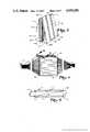
- FIG. 1is a perspective view of a light transfer device embodying features of the present invention
- FIG. 2is an enlarged perspective view of the upper left corner of the device shown in FIG. 2 with a portion of one fiber ribbon removed;
- FIG. 3is a perspective view illustrating a preferred method of making the device of FIG. 1 with the second locator members omitted;
- FIG. 4is a top plan view of the assembly of FIG. 3;
- FIG. 5is a sectional view taken along lines 5--5 of FIG. 3 with a portion of the fiber ribbon removed from the open slot;
- FIG. 6is a fragmentary cross-sectional view of the locator body shown in FIG. 5;
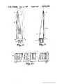
- FIG. 7is a perspective view of a portion of a solid locator body
- FIG. 8is a side elevation view of the locator body with only portions of the fiber ribbon shown in place;
- FIG. 9is a side elevation view of the opposite side of the locator body
- FIG. 10is an end elevation view of the wide end of two of the image transfer devices that are separated before being brought together in a modular assembly
- FIG. 11is a modular assembly of four of the light transfer devices shown in FIG. 1;
- FIG. 12is a fragmentary plan view of the central portion of the modular assembly shown in FIG. 11.
- a light transfer device 11including a plurality of optical fibers 12 forming an end surface 13 at one end and end surface 14 at the opposite end.
- lightwill travel through light transfer device 11 and pass into either end surface in either direction (bi-directional) so that the end surfaces 13 and 14 are alternately a viewing surface or a light projecting surface.
- the optical fibers 12have adjacent end portions supported by a locator body 21.
- Body 21is generally wedge-shaped and is formed with a multiplicity of interior parallel slots 22 extending therethrough with longitudinally facing openings at the ends, the slot to the far left as seen in FIG. 1 being open and the remaining slots being closed and all of the slots being of an identical size in transverse cross section.
- the locator body 21generally stated, has fiber supporting surfaces provided by slots 22 which precisely locate the optical fibers in relation to one another and, when adhered to these supporting surfaces, mechanically hold the fibers 12 in a fixed position relative to one another.
- FIG. 5For the purpose of further defining the fiber supporting surfaces and their positions relative to one another, reference is made to FIG. 5 and to the use of a Cartesian coordinate system with an X, Y, Z axis located on the upper left corner of the open slot, as seen in FIG. 5, which is selected as the reference slot and designated 22R.
- the axes X, Y and Z of a Cartesian coordinate systemare perpendicular to one another, as are the three planes XZ, YZ, and YX defined by these axes.
- the suffix "R"is used to distinguish the reference slot and the surfaces forming this slot from the further slots and to designate the fibers carried in the reference slot.
- FIGS. 3-5show the preferred structure that is used to form two identical light transfer devices, as is described hereinafter.
- the reference slot 22R related to the coordinate system in FIG. 5has a first reference supporting surface 24R in the YZ plane for a reference end fiber 12R and a second reference surface 25R in the XZ plane for the reference end fiber 12R. These surfaces 24R and 25R locate a reference end fiber 12R along the YZ and XZ planes, respectively, and perpendicular to the YX plane.
- Each additional slot 22 in body 21, then,has what is referred to as a first supporting surface 24 in the YZ plane and a second supporting surface 25 in a second plane parallel to and displaced a fixed distance from the reference second plane.
- first and second supporting surfaceslocate the fibers and, when adhered to the fibers, mechanically hold the fibers against movement relative to one another in three mutually perpendicular planes, which prevents the plurality of spaced fiber ribbons from being skewed or squirreled at an angle along the lengths thereof.
- a preferred method of making the above described locator bodyis to use a plurality of identical generally channel-shaped locator members 31 stacked one on another, as shown in FIGS. 3-6.
- Each locator member 31has a spacer portion 32 and stepped out projecting portions 33 and 34 at the opposite ends of the spacer portion, together with stepped in notched portions 43 and 54 opposite projecting portions 33 and 34, respectively.
- the spacer portion 32has oppositely disposed surfaces 25 and 45
- projecting portion 33has surfaces 24 and 38 at right angles to one another
- projecting portion 34has surfaces 44 and 48 at right angles to one another
- notched portion 43has surfaces 36 and 37 at right angles to one another
- notched portion 54has surfaces 46 and 47 at right angles to one another.
- the notched portions 43 and 54are complementary in shape with projections 33 and 34 but are not as deep as the projections so that, when the notched portions 43 and 54 are placed on the projecting portions of another locator member 31 in a nesting or stacked relation, the spacing for slot 22 is formed. It will be noted that surfaces 24 and 37 are in the same plane and surfaces 44 and 47 are in the same plane.
- each locator memberis shown tapered or V-shaped, as indicated at 39, so that there are no sharp corners or right angle bends for the relatively brittle fibers.
- an adhesiveis placed along the inside of the channel of one member 31 and a fiber ribbon 26 is placed on the inside surfaces with the end fibers of the ribbon abutting against adjacent inside surfaces 24 and 44 to hold the ribbon in place.
- the channel defined by surfaces 24 and 44is the same width as the fiber ribbon.
- the adhesiveis placed on the top of the ribbon so disposed in the channel and on surfaces 48 and 38.
- a second locator member 31is placed on the first with the spacer portion surfaces 37 and 47 inserting into the channel surfaces 24 and 44, respectively, the spacer portion surface 45 pressing down on the top of the fiber ribbon. Succeeding locator members 31 and fiber ribbons are stacked one on the other until the desired stack is achieved. The depth of the stack establishes the lateral extent of the body 21, as seen in FIG. 1.
- the fibers 12 secured in the assembled channel-shaped locator member 31are then cut down through the stack, as shown in FIG. 3, along a plane designated 49 that is rotated 90° to the plane of the fiber ribbon or XZ plane and at a slight angle, designated A, to the rotated plane to define the end surface 13 with the cut fiber ends.
- This method of makingprovides two identical light transfer devices 11.
- a sharp angle Aprovides greater surface area.
- a preferred angle Ais between 8° and 10° to the axis of the fibers.
- the opposite end portions of the fibers 12preferably are supported in the same manner, using a locator body 51 with interior slots 52, again shown as made up of a plurality of channel-shaped locator members 61 stacked one on another in the same manner as are locator members 31 above described.
- These channel-shaped memberspreferably have the same channel width as the ribbon but decrease in thickness along their length to bring the fibers to a solid bundle having a uniform array of rows and columns at the end surface 14.
- An alternative to the stacked channel-shaped locator members above describedwould be to form a unitary rectangular block 61 and to use a cutting tool such as a laser to form the reference slot 22R and slots 22 for a ribbon of fibers, as is illustrated in FIG. 6.
- An adhesivewould be placed on the ribbon and the ribbon of fibers would be slid through the longitudinally facing openings of the slots.
- the support body 21 above describedis particularly suitable for being stacked side by side and end to end to enlarge the end surfaces as required.
- a modular assembly of two of the devices which form end surfaces 13 side by side and two more end to endis shown in FIG. 11.
- the two side by sideare shown separated in FIG. 10 but when brought together the projecting portion 33 and ribbon portion 26 along one side mate with the notched portion 43 and surface 45 of the adjacent device to provide uniformity in the succession of the fiber ribbon 26 and spacer portion 32 between the two devices.
- a pin 57extends through alined holes in the projecting portion 33 of the bodies 21 to position these bodies and hold them side by side.
- an angular cut 71is provided along projecting section 33 at the narrow end to allow the ribbons to pass along the back side of the modular array, as shown in FIG. 12.
- the ribbonsline up in straight lines and the spacer portions 32 line up in straight lines.
- the end surface 13 of the device 11 in the upper right-hand cornerhas its end surface 14 also in the upper right-hand corner.
- the fibers in the end surfaceproceed from top to bottom, while corresponding fibers at end surface 14 proceed from bottom to top in the ribbon.
- a block 65is shown adjacent surface 14 in the modular assembly. This may be used for inputting light by a variety of means including, but not limited to, kinescopes (crt), microshutters with a light source behind, lasers, liquid crystal shutters, or similar light control mechanisms.
- the cut ends of the fibersmay be located with a material such as phosphorus encased in a vacuum and may have either light or electron beams projected at the cut end surface. If the direction of light were to be reversed through the device 11, the block 65 would be receiving light from a source at end surface 13.
- the lateral extent or width of surface 13is 8" and the vertical extent is 6" for a 4:3 width to height ratio.
- Each ribbonis 1" wide and contains 333 fibers, each of which is 0.003" in diameter.
- the center to center spacing of the ribbonsis 0.018".
- the spacer sectionis 0.015".
- the matrix at the end surface 14is 1" by 1.332", providing a gain of 36:1.
- the angle of cut Ais 9.6°.
- a preferred fiber for this applicationis in the range of 3 to 100 microns in diameter and has a wavelength of 400-700 nanometers.
- the fiberis coated black to prevent cross-talk and has a 3 db. loss over 1000'. If the ends are coated with a phosphor, an electron beam is able to excite these ends.
Landscapes
- Physics & Mathematics (AREA)
- General Physics & Mathematics (AREA)
- Optics & Photonics (AREA)
- Optical Fibers, Optical Fiber Cores, And Optical Fiber Bundles (AREA)
- Mechanical Coupling Of Light Guides (AREA)
Abstract
Description
Claims (16)
Priority Applications (8)
| Application Number | Priority Date | Filing Date | Title |
|---|---|---|---|
| US06/575,816US4650280A (en) | 1984-02-01 | 1984-02-01 | Fiber optic light transfer device, modular assembly, and method of making |
| CA000473237ACA1251073A (en) | 1984-02-01 | 1985-01-31 | Fiber optic light transfer device, modular assembly, and method of making |
| EP85300692AEP0151047A3 (en) | 1984-02-01 | 1985-02-01 | Fiber optic light transfer device, modular assembly, and method of making |
| JP60018479AJPS60181706A (en) | 1984-02-01 | 1985-02-01 | Optical fiber light transmission device, module assembly and manufacturing method thereof |
| US07/025,385US4773730A (en) | 1984-02-01 | 1987-03-12 | Fiber optic light transfer devices and assemblies |
| US07/122,407US4786139A (en) | 1984-02-01 | 1987-11-19 | Optical fiber light transfer apparatus, method and apparatus for making same |
| US07/220,410US4867530A (en) | 1984-02-01 | 1988-07-19 | Low Resolution fiber optic light transfer device |
| US07/273,235US4950357A (en) | 1984-02-01 | 1988-11-18 | Apparatus for making light transfer devices |
Applications Claiming Priority (1)
| Application Number | Priority Date | Filing Date | Title |
|---|---|---|---|
| US06/575,816US4650280A (en) | 1984-02-01 | 1984-02-01 | Fiber optic light transfer device, modular assembly, and method of making |
Related Child Applications (3)
| Application Number | Title | Priority Date | Filing Date |
|---|---|---|---|
| US07/025,385Continuation-In-PartUS4773730A (en) | 1984-02-01 | 1987-03-12 | Fiber optic light transfer devices and assemblies |
| US2528287AContinuation-In-Part | 1984-02-01 | 1987-03-12 | |
| US2596187AContinuation-In-Part | 1984-02-01 | 1987-03-16 |
Publications (1)
| Publication Number | Publication Date |
|---|---|
| US4650280Atrue US4650280A (en) | 1987-03-17 |
Family
ID=24301826
Family Applications (1)
| Application Number | Title | Priority Date | Filing Date |
|---|---|---|---|
| US06/575,816Expired - LifetimeUS4650280A (en) | 1984-02-01 | 1984-02-01 | Fiber optic light transfer device, modular assembly, and method of making |
Country Status (4)
| Country | Link |
|---|---|
| US (1) | US4650280A (en) |
| EP (1) | EP0151047A3 (en) |
| JP (1) | JPS60181706A (en) |
| CA (1) | CA1251073A (en) |
Cited By (33)
| Publication number | Priority date | Publication date | Assignee | Title |
|---|---|---|---|---|
| US4747648A (en)* | 1985-01-24 | 1988-05-31 | Drd Ltd. | Optical fiber display and optical train for same |
| US4756590A (en)* | 1985-09-03 | 1988-07-12 | American Telephone And Telegraph Company, At&T Bell Laboratories | Optical component package |
| US4773730A (en)* | 1984-02-01 | 1988-09-27 | Advance Display Technologies, Inc. | Fiber optic light transfer devices and assemblies |
| US4786139A (en)* | 1984-02-01 | 1988-11-22 | Advance Display Technologies, Inc. | Optical fiber light transfer apparatus, method and apparatus for making same |
| US4825341A (en)* | 1987-11-17 | 1989-04-25 | Fiberstars, Inc. | Cooled lighting apparatus and method |
| US4867530A (en)* | 1984-02-01 | 1989-09-19 | Advance Display Technologies, Inc. | Low Resolution fiber optic light transfer device |
| US4871228A (en)* | 1982-07-21 | 1989-10-03 | U.S. Philips Corporation | Image transfer apparatus utilizing optical fibers |
| US4907132A (en)* | 1988-03-22 | 1990-03-06 | Lumitex, Inc. | Light emitting panel assemblies and method of making same |
| US4929048A (en)* | 1988-11-10 | 1990-05-29 | Fiberview Corporation | Fiber optic display |
| US4950357A (en)* | 1984-02-01 | 1990-08-21 | Advance Display Technologies, Inc. | Apparatus for making light transfer devices |
| US4973128A (en)* | 1989-05-01 | 1990-11-27 | Hodges Marvin P | High gain optical fiber viewing device |
| US5009475A (en)* | 1989-12-27 | 1991-04-23 | Advance Display Technologies, Inc. | Image transfer device and method of manufacture |
| US5015842A (en)* | 1989-06-01 | 1991-05-14 | United Technologies Corporation | High density fiber optic damage detection system |
| US5021928A (en)* | 1982-09-29 | 1991-06-04 | Maurice Daniel | Flat panel illumination system |
| US5053765A (en)* | 1988-01-11 | 1991-10-01 | Seiko Epson Corporation | Light guide type display apparatus |
| US5121459A (en)* | 1991-07-24 | 1992-06-09 | Photon Imaging Corp. | Fiber optic bundle and method of manufacture |
| US5130794A (en)* | 1990-03-29 | 1992-07-14 | Ritchey Kurtis J | Panoramic display system |
| US5222179A (en)* | 1992-03-02 | 1993-06-22 | Porta Systems Corp. | Means for routing ribbon type fiber optic cable |
| US5293437A (en)* | 1992-06-03 | 1994-03-08 | Visual Optics, Inc. | Fiber optic display with direct driven optical fibers |
| USD347003S (en) | 1992-02-21 | 1994-05-17 | Fox Allen J | Three-dimensional image optical fiber screen |
| US5493627A (en)* | 1988-01-15 | 1996-02-20 | Sippican, Inc. | Waveguide pack |
| US5614961A (en)* | 1993-02-03 | 1997-03-25 | Nitor | Methods and apparatus for image projection |
| US5768096A (en)* | 1996-10-30 | 1998-06-16 | Hewlett-Packard Company | Portable computer with movable display panels forming a concatenated display screen in response to opening the computer |
| US5832168A (en)* | 1997-07-08 | 1998-11-03 | Advance Display Technologies, Inc. | Optical fiber light transfer apparatus |
| US6195016B1 (en) | 1999-08-27 | 2001-02-27 | Advance Display Technologies, Inc. | Fiber optic display system with enhanced light efficiency |
| US6304703B1 (en)* | 2000-01-13 | 2001-10-16 | Transvision, Inc. | Tiled fiber optic display apparatus |
| US6337945B1 (en) | 1999-09-15 | 2002-01-08 | Supervision International, Inc. | Fiber optic light bar |
| US6396985B2 (en)* | 2000-01-13 | 2002-05-28 | Transvision, Inc. | Contoured large screen display apparatus |
| US6418267B1 (en)* | 2000-01-13 | 2002-07-09 | Mediapull, Inc. | Micro-display driven tiled electro-optic display apparatus |
| US6484952B2 (en) | 2000-12-20 | 2002-11-26 | Super Vision International, Inc. | Fiber optic illuminated waterfall |
| US6571043B1 (en)* | 2000-01-13 | 2003-05-27 | Transvision | Large screen fiber optic display with high fiber density and method for its rapid assembly |
| US6618528B2 (en)* | 2000-01-13 | 2003-09-09 | Transvision, Inc. | Optical display apparatus |
| US20130229822A1 (en)* | 2012-03-02 | 2013-09-05 | Advanced Optoelectronic Technology, Inc. | Backlight module having optcial fiber |
Families Citing this family (3)
| Publication number | Priority date | Publication date | Assignee | Title |
|---|---|---|---|---|
| US6538045B1 (en) | 1999-12-23 | 2003-03-25 | Dsm N.V. | Optical fiber coating compositions containing secondary or tertiary amino silicone-containing additive |
| TWM419114U (en)* | 2011-06-10 | 2011-12-21 | Hon Hai Prec Ind Co Ltd | Optical waveguide ribbon |
| CN113109551B (en)* | 2021-03-30 | 2023-06-16 | 海南华盛混凝土有限公司 | Concrete slump expansion testing device |
Citations (5)
| Publication number | Priority date | Publication date | Assignee | Title |
|---|---|---|---|---|
| US3043910A (en)* | 1958-05-19 | 1962-07-10 | American Optical Corp | Fiber optical image transfer devices |
| US3141105A (en)* | 1963-12-19 | 1964-07-14 | American Optical Corp | Cathode ray tube with composite multiple glass fibre face |
| US3644922A (en)* | 1969-07-14 | 1972-02-22 | Image Products Corp | High-resolution fiber optic display and microfilm printer |
| US4116739A (en)* | 1976-11-26 | 1978-09-26 | New York Institute Of Technology | Method of forming an optical fiber device |
| US4208096A (en)* | 1976-11-26 | 1980-06-17 | New York Institute Of Technology | Optical display apparatus |
Family Cites Families (4)
| Publication number | Priority date | Publication date | Assignee | Title |
|---|---|---|---|---|
| US3909109A (en)* | 1971-08-09 | 1975-09-30 | Jenaer Glaswerk Schott & Gen | Optical fiber image magnifying apparatus |
| JPS5351754A (en)* | 1976-10-21 | 1978-05-11 | Nippon Telegr & Teleph Corp <Ntt> | Optical fiber sheet |
| DE3028194A1 (en)* | 1980-07-25 | 1982-05-06 | Triumph-Adler Aktiengesellschaft für Büro- und Informationstechnik, 8500 Nürnberg | COPIER |
| JPS5878105A (en)* | 1982-07-22 | 1983-05-11 | Nippon Sheet Glass Co Ltd | Manufacture of focusing optical transmission body |
- 1984
- 1984-02-01USUS06/575,816patent/US4650280A/ennot_activeExpired - Lifetime
- 1985
- 1985-01-31CACA000473237Apatent/CA1251073A/ennot_activeExpired
- 1985-02-01JPJP60018479Apatent/JPS60181706A/enactiveGranted
- 1985-02-01EPEP85300692Apatent/EP0151047A3/ennot_activeWithdrawn
Patent Citations (5)
| Publication number | Priority date | Publication date | Assignee | Title |
|---|---|---|---|---|
| US3043910A (en)* | 1958-05-19 | 1962-07-10 | American Optical Corp | Fiber optical image transfer devices |
| US3141105A (en)* | 1963-12-19 | 1964-07-14 | American Optical Corp | Cathode ray tube with composite multiple glass fibre face |
| US3644922A (en)* | 1969-07-14 | 1972-02-22 | Image Products Corp | High-resolution fiber optic display and microfilm printer |
| US4116739A (en)* | 1976-11-26 | 1978-09-26 | New York Institute Of Technology | Method of forming an optical fiber device |
| US4208096A (en)* | 1976-11-26 | 1980-06-17 | New York Institute Of Technology | Optical display apparatus |
Non-Patent Citations (2)
| Title |
|---|
| Casler, "Manufacturing Matched Fiber Optical Arrays" IBM Tech. Disc., vol. 19, No. 3, 8/71, p. 829. |
| Casler, Manufacturing Matched Fiber Optical Arrays IBM Tech. Disc., vol. 19, No. 3, 8/71, p. 829.* |
Cited By (37)
| Publication number | Priority date | Publication date | Assignee | Title |
|---|---|---|---|---|
| US4871228A (en)* | 1982-07-21 | 1989-10-03 | U.S. Philips Corporation | Image transfer apparatus utilizing optical fibers |
| US5021928A (en)* | 1982-09-29 | 1991-06-04 | Maurice Daniel | Flat panel illumination system |
| US4786139A (en)* | 1984-02-01 | 1988-11-22 | Advance Display Technologies, Inc. | Optical fiber light transfer apparatus, method and apparatus for making same |
| US4773730A (en)* | 1984-02-01 | 1988-09-27 | Advance Display Technologies, Inc. | Fiber optic light transfer devices and assemblies |
| US4867530A (en)* | 1984-02-01 | 1989-09-19 | Advance Display Technologies, Inc. | Low Resolution fiber optic light transfer device |
| US4950357A (en)* | 1984-02-01 | 1990-08-21 | Advance Display Technologies, Inc. | Apparatus for making light transfer devices |
| US4747648A (en)* | 1985-01-24 | 1988-05-31 | Drd Ltd. | Optical fiber display and optical train for same |
| US4756590A (en)* | 1985-09-03 | 1988-07-12 | American Telephone And Telegraph Company, At&T Bell Laboratories | Optical component package |
| US4825341A (en)* | 1987-11-17 | 1989-04-25 | Fiberstars, Inc. | Cooled lighting apparatus and method |
| US5053765A (en)* | 1988-01-11 | 1991-10-01 | Seiko Epson Corporation | Light guide type display apparatus |
| US5493627A (en)* | 1988-01-15 | 1996-02-20 | Sippican, Inc. | Waveguide pack |
| US4907132A (en)* | 1988-03-22 | 1990-03-06 | Lumitex, Inc. | Light emitting panel assemblies and method of making same |
| US4929048A (en)* | 1988-11-10 | 1990-05-29 | Fiberview Corporation | Fiber optic display |
| US4973128A (en)* | 1989-05-01 | 1990-11-27 | Hodges Marvin P | High gain optical fiber viewing device |
| US5015842A (en)* | 1989-06-01 | 1991-05-14 | United Technologies Corporation | High density fiber optic damage detection system |
| US5009475A (en)* | 1989-12-27 | 1991-04-23 | Advance Display Technologies, Inc. | Image transfer device and method of manufacture |
| US5130794A (en)* | 1990-03-29 | 1992-07-14 | Ritchey Kurtis J | Panoramic display system |
| US5121459A (en)* | 1991-07-24 | 1992-06-09 | Photon Imaging Corp. | Fiber optic bundle and method of manufacture |
| USD347003S (en) | 1992-02-21 | 1994-05-17 | Fox Allen J | Three-dimensional image optical fiber screen |
| US5222179A (en)* | 1992-03-02 | 1993-06-22 | Porta Systems Corp. | Means for routing ribbon type fiber optic cable |
| US5293437A (en)* | 1992-06-03 | 1994-03-08 | Visual Optics, Inc. | Fiber optic display with direct driven optical fibers |
| US5715021A (en)* | 1993-02-03 | 1998-02-03 | Nitor | Methods and apparatus for image projection |
| US5920361A (en)* | 1993-02-03 | 1999-07-06 | Nitor | Methods and apparatus for image projection |
| US5614961A (en)* | 1993-02-03 | 1997-03-25 | Nitor | Methods and apparatus for image projection |
| US5768096A (en)* | 1996-10-30 | 1998-06-16 | Hewlett-Packard Company | Portable computer with movable display panels forming a concatenated display screen in response to opening the computer |
| US5832168A (en)* | 1997-07-08 | 1998-11-03 | Advance Display Technologies, Inc. | Optical fiber light transfer apparatus |
| US6195016B1 (en) | 1999-08-27 | 2001-02-27 | Advance Display Technologies, Inc. | Fiber optic display system with enhanced light efficiency |
| US6337945B1 (en) | 1999-09-15 | 2002-01-08 | Supervision International, Inc. | Fiber optic light bar |
| US6396985B2 (en)* | 2000-01-13 | 2002-05-28 | Transvision, Inc. | Contoured large screen display apparatus |
| US6304703B1 (en)* | 2000-01-13 | 2001-10-16 | Transvision, Inc. | Tiled fiber optic display apparatus |
| US6418267B1 (en)* | 2000-01-13 | 2002-07-09 | Mediapull, Inc. | Micro-display driven tiled electro-optic display apparatus |
| US6571043B1 (en)* | 2000-01-13 | 2003-05-27 | Transvision | Large screen fiber optic display with high fiber density and method for its rapid assembly |
| US6618529B2 (en)* | 2000-01-13 | 2003-09-09 | Transvision, Inc. | Tiled fiber optic display apparatus |
| US6618528B2 (en)* | 2000-01-13 | 2003-09-09 | Transvision, Inc. | Optical display apparatus |
| US6484952B2 (en) | 2000-12-20 | 2002-11-26 | Super Vision International, Inc. | Fiber optic illuminated waterfall |
| US20130229822A1 (en)* | 2012-03-02 | 2013-09-05 | Advanced Optoelectronic Technology, Inc. | Backlight module having optcial fiber |
| US8985826B2 (en)* | 2012-03-02 | 2015-03-24 | Advanced Optoelectronic Technology, Inc. | Backlight module having optcial fiber |
Also Published As
| Publication number | Publication date |
|---|---|
| EP0151047A2 (en) | 1985-08-07 |
| EP0151047A3 (en) | 1987-01-14 |
| CA1251073A (en) | 1989-03-14 |
| JPH0583881B2 (en) | 1993-11-30 |
| JPS60181706A (en) | 1985-09-17 |
Similar Documents
| Publication | Publication Date | Title |
|---|---|---|
| US4650280A (en) | Fiber optic light transfer device, modular assembly, and method of making | |
| US4773730A (en) | Fiber optic light transfer devices and assemblies | |
| US4867530A (en) | Low Resolution fiber optic light transfer device | |
| US5009475A (en) | Image transfer device and method of manufacture | |
| US3919037A (en) | Optical fiber splicing apparatus | |
| US4116739A (en) | Method of forming an optical fiber device | |
| US4028162A (en) | Method of splicing pairs of arrayed or individual fibers utilizing optical fiber aligning grooves | |
| US4762387A (en) | Array connector for optical fibers | |
| EP0554672B1 (en) | Fibre optic wavelength selecting device | |
| US4912314A (en) | Channel type electron multiplier with support rod structure | |
| CA1145173A (en) | Apparatus for generating pulsed light beams | |
| US7892381B2 (en) | Method for forming an optical converter | |
| US4126804A (en) | Strip microchannel electron multiplier array support structure | |
| US4124444A (en) | Nuclear fuel rod supporting arrangement | |
| JPS58140703A (en) | Array apparatus for optical fiber | |
| US4598975A (en) | Multiple fiber linear array and method of making same | |
| US6375149B1 (en) | Mold for forming flat panel display spacers | |
| US4402568A (en) | Method and apparatus for an optical four-gate coupler | |
| JPS62287208A (en) | Fiber plate with coding fiber | |
| US4950357A (en) | Apparatus for making light transfer devices | |
| JP3076126B2 (en) | Optical fiber two-dimensional array connector and manufacturing method thereof | |
| GB2070852A (en) | Beam guide structure for a flat panel display device | |
| JPH03155503A (en) | Optical fiber array | |
| JP3198039B2 (en) | Optical fiber array component and method of manufacturing the same | |
| GB2070851A (en) | Unitary beam guide/electron gun assembly for flat panel display devices |
Legal Events
| Date | Code | Title | Description |
|---|---|---|---|
| STCF | Information on status: patent grant | Free format text:PATENTED CASE | |
| CC | Certificate of correction | ||
| AS | Assignment | Owner name:CORPORATE PARTNERS, INC., 5956 SHERRY LANE, STE. 9 Free format text:SECURITY INTEREST;ASSIGNOR:ADVANCE DISPLAY TECHNOLOGIES, INC.;REEL/FRAME:004996/0845 Effective date:19881201 Owner name:ADVANCED DISPLAY TECHNOLOGIES, INC., 425 CORPORATE Free format text:ASSIGNMENT OF ASSIGNORS INTEREST.;ASSIGNOR:SEDLMAYR, STEVEN R.;REEL/FRAME:004996/0867 Effective date:19881026 | |
| FPAY | Fee payment | Year of fee payment:4 | |
| AS | Assignment | Owner name:ULTRATECH KNOWLEDGE SYSTEMS, INCORPORATED, 9940 EA Free format text:ASSIGNMENT OF ASSIGNORS INTEREST.;ASSIGNOR:CORPORATE PARTNERS INCORPORATED;REEL/FRAME:005665/0831 Effective date:19900919 Owner name:CORPORATE PARTNERS, INCORPORATED, 16610 DALLAS PAR Free format text:ASSIGNMENT OF ASSIGNORS INTEREST.;ASSIGNOR:ADVANCED DISPLAY TECHNOLOGIES INCORPORATED;REEL/FRAME:005665/0805 Effective date:19900917 Owner name:CAPROCK FEDERAL SAVINGS AND LOAN ASSOCIATION, 4401 Free format text:SECURITY INTEREST;ASSIGNOR:CORPORATE PARTNERS INCORPORATED;REEL/FRAME:005665/0806 Effective date:19900917 Owner name:CAPROCK FEDERAL SAVINGS AND LOAN ASSOCIATION, 4401 Free format text:SECURITY INTEREST;ASSIGNOR:CORPORATE PARTNERS INCORPORATED;REEL/FRAME:005665/0851 Effective date:19900919 Owner name:CORPORATE PARTNERS, INCORPORATED, 16610 DALLAS PAR Free format text:SECURITY INTEREST;ASSIGNOR:ULTRATECH KNOWLEDGE SYSTEMS, INCORPORATED;REEL/FRAME:005665/0841 Effective date:19900919 Owner name:CORPORATE PARTNERS, INCORPORATED, 16610 DALLAS PAR Free format text:ASSIGNMENT OF ASSIGNORS INTEREST.;ASSIGNOR:ADVANCED DISPLAY TECHNOLOGIES, INCORPORATED;REEL/FRAME:005521/0447 Effective date:19900917 | |
| FPAY | Fee payment | Year of fee payment:8 | |
| REMI | Maintenance fee reminder mailed | ||
| FEPP | Fee payment procedure | Free format text:PAYOR NUMBER ASSIGNED (ORIGINAL EVENT CODE: ASPN); ENTITY STATUS OF PATENT OWNER: SMALL ENTITY | |
| FPAY | Fee payment | Year of fee payment:12 | |
| SULP | Surcharge for late payment |