US4648872A - Volumetric pump with replaceable reservoir assembly - Google Patents
Volumetric pump with replaceable reservoir assemblyDownload PDFInfo
- Publication number
- US4648872A US4648872AUS06/551,851US55185183AUS4648872AUS 4648872 AUS4648872 AUS 4648872AUS 55185183 AUS55185183 AUS 55185183AUS 4648872 AUS4648872 AUS 4648872A
- Authority
- US
- United States
- Prior art keywords
- piston
- drive
- reservoir
- stem
- head portion
- Prior art date
- Legal status (The legal status is an assumption and is not a legal conclusion. Google has not performed a legal analysis and makes no representation as to the accuracy of the status listed.)
- Expired - Lifetime
Links
- 239000012530fluidSubstances0.000claimsdescription11
- 238000006073displacement reactionMethods0.000claimsdescription8
- 230000000740bleeding effectEffects0.000claimsdescription2
- 238000001802infusionMethods0.000abstractdescription20
- 239000003814drugSubstances0.000description14
- 229940079593drugDrugs0.000description12
- 238000003780insertionMethods0.000description5
- 230000037431insertionEffects0.000description5
- 210000002445nippleAnatomy0.000description4
- 230000002459sustained effectEffects0.000description4
- 238000012986modificationMethods0.000description3
- 230000004048modificationEffects0.000description3
- 230000000737periodic effectEffects0.000description3
- 230000009467reductionEffects0.000description3
- 239000000356contaminantSubstances0.000description2
- 238000011161developmentMethods0.000description2
- 230000005484gravityEffects0.000description2
- 239000007924injectionSubstances0.000description2
- 238000002347injectionMethods0.000description2
- 230000013011matingEffects0.000description2
- 230000007246mechanismEffects0.000description2
- 238000005086pumpingMethods0.000description2
- 230000000717retained effectEffects0.000description2
- 238000007789sealingMethods0.000description2
- 230000004913activationEffects0.000description1
- 238000013459approachMethods0.000description1
- 230000001580bacterial effectEffects0.000description1
- 230000002457bidirectional effectEffects0.000description1
- 238000004891communicationMethods0.000description1
- 150000001875compoundsChemical class0.000description1
- 238000010276constructionMethods0.000description1
- 238000011109contaminationMethods0.000description1
- 230000008878couplingEffects0.000description1
- 238000010168coupling processMethods0.000description1
- 238000005859coupling reactionMethods0.000description1
- 238000013479data entryMethods0.000description1
- 230000001419dependent effectEffects0.000description1
- 238000013461designMethods0.000description1
- 238000001514detection methodMethods0.000description1
- 230000008030eliminationEffects0.000description1
- 238000003379elimination reactionMethods0.000description1
- 230000007274generation of a signal involved in cell-cell signalingEffects0.000description1
- 238000011534incubationMethods0.000description1
- 208000015181infectious diseaseDiseases0.000description1
- 230000002458infectious effectEffects0.000description1
- 239000003978infusion fluidSubstances0.000description1
- 238000012423maintenanceMethods0.000description1
- 238000004519manufacturing processMethods0.000description1
- 230000004060metabolic processEffects0.000description1
- 238000000034methodMethods0.000description1
- 230000000474nursing effectEffects0.000description1
- 230000003287optical effectEffects0.000description1
- 229920001084poly(chloroprene)Polymers0.000description1
- 230000001698pyrogenic effectEffects0.000description1
- 238000002601radiographyMethods0.000description1
- 230000011664signalingEffects0.000description1
- 238000002560therapeutic procedureMethods0.000description1
- 231100000331toxicToxicity0.000description1
- 230000002588toxic effectEffects0.000description1
- 230000000472traumatic effectEffects0.000description1
- 238000013022ventingMethods0.000description1
Images


Classifications
- A—HUMAN NECESSITIES
- A61—MEDICAL OR VETERINARY SCIENCE; HYGIENE
- A61M—DEVICES FOR INTRODUCING MEDIA INTO, OR ONTO, THE BODY; DEVICES FOR TRANSDUCING BODY MEDIA OR FOR TAKING MEDIA FROM THE BODY; DEVICES FOR PRODUCING OR ENDING SLEEP OR STUPOR
- A61M5/00—Devices for bringing media into the body in a subcutaneous, intra-vascular or intramuscular way; Accessories therefor, e.g. filling or cleaning devices, arm-rests
- A61M5/14—Infusion devices, e.g. infusing by gravity; Blood infusion; Accessories therefor
- A61M5/142—Pressure infusion, e.g. using pumps
- A61M5/145—Pressure infusion, e.g. using pumps using pressurised reservoirs, e.g. pressurised by means of pistons
- A61M5/1452—Pressure infusion, e.g. using pumps using pressurised reservoirs, e.g. pressurised by means of pistons pressurised by means of pistons
- A61M5/1456—Pressure infusion, e.g. using pumps using pressurised reservoirs, e.g. pressurised by means of pistons pressurised by means of pistons with a replaceable reservoir comprising a piston rod to be moved into the reservoir, e.g. the piston rod is part of the removable reservoir
- A—HUMAN NECESSITIES
- A61—MEDICAL OR VETERINARY SCIENCE; HYGIENE
- A61M—DEVICES FOR INTRODUCING MEDIA INTO, OR ONTO, THE BODY; DEVICES FOR TRANSDUCING BODY MEDIA OR FOR TAKING MEDIA FROM THE BODY; DEVICES FOR PRODUCING OR ENDING SLEEP OR STUPOR
- A61M5/00—Devices for bringing media into the body in a subcutaneous, intra-vascular or intramuscular way; Accessories therefor, e.g. filling or cleaning devices, arm-rests
- A61M5/14—Infusion devices, e.g. infusing by gravity; Blood infusion; Accessories therefor
- A61M5/142—Pressure infusion, e.g. using pumps
- A61M5/145—Pressure infusion, e.g. using pumps using pressurised reservoirs, e.g. pressurised by means of pistons
- A61M5/1452—Pressure infusion, e.g. using pumps using pressurised reservoirs, e.g. pressurised by means of pistons pressurised by means of pistons
- A61M2005/14573—Pressure infusion, e.g. using pumps using pressurised reservoirs, e.g. pressurised by means of pistons pressurised by means of pistons with a replaceable reservoir for quick connection/disconnection with a driving system
- Y—GENERAL TAGGING OF NEW TECHNOLOGICAL DEVELOPMENTS; GENERAL TAGGING OF CROSS-SECTIONAL TECHNOLOGIES SPANNING OVER SEVERAL SECTIONS OF THE IPC; TECHNICAL SUBJECTS COVERED BY FORMER USPC CROSS-REFERENCE ART COLLECTIONS [XRACs] AND DIGESTS
- Y10—TECHNICAL SUBJECTS COVERED BY FORMER USPC
- Y10S—TECHNICAL SUBJECTS COVERED BY FORMER USPC CROSS-REFERENCE ART COLLECTIONS [XRACs] AND DIGESTS
- Y10S128/00—Surgery
- Y10S128/12—Pressure infusion
Definitions
- This inventionrelates to medical infusion pumps and more particularly pumps capable of home use by ambulatory patients and pumps having built in controls for sustained or periodic infusions over a substantial time.
- medication infusionUnlike the case with a parenteral fluid administration apparatus, which typically operates by gravity flow from a relatively large reservoir of fluid, medication infusion generally involves administration of small dosages so as to achieve a prescribed optimum level of medication in the bloodstream of the patient. Due to differences in the rates of metabolism of, or elimination of, various medicines, the attainment of precise bloodstream medication levels is usually achieved by the periodic administration of a dosage of medication, where determination of the precise dosage and the correct interval between doses will depend on the particular medication involved as well as criteria peculiar to the patient.
- Another, general purpose, species of pumputilizes a motor or clock drive to power a pushing mechanism, using a leadscrew or rack, for moving a plunger arrangement.
- Examples of such devicesare my medication injection device disclosed in U.S. Pat. No. 3,858,581, or that of U.S. Pat. No. 4,059,110.
- Such devicesare more compact and are reasonably well adapted for use as bedside periodic infusion devices in a hospital setting. However these devices tend to be somewhat bulky and, for this reason, are less than optimal for use on an ambulatory patient.
- Each of the prior art devicesalso suffers from a looseness in its mechanical drive components which requires close attention when setting up the initial pumping operation to ensure that the device actually pumps a full dose during the first duty cycle of its activation. Additionally each of the prior art devices has a rather complex mechanical structure, introducing significant inertial and frictional factors affecting the ease and cost of maintaining the units in reliable operating condition over extended times, and making them unsuitable for battery powered operation.
- the present inventionovercomes the foregoing limitations by providing a simplified mechanical structure for a pump including a reservoir, piston and drive member, in which the drive member may be internally threaded for a substantial length.
- a relatively short drive screwwhich may be motor driven, engages the drive member to propel the piston in the reservoir.
- the reservoir, piston, and drive membermay be an assembly that can be removed from the pump.
- interlocking detents on the piston and reservoir wallsmay be used to prevent withdrawal or reuse of the reservoir assembly or components after use.
- a shearable stemwhich may be integrally formed with the piston face, holds the piston and drive member together for setting up or bleeding the pump. The stem then is sheared off by twisting so that the piston face floats free, preventing re-use of the reservoir assembly.
- the inventionis well adapted for use with battery powered drive, and microprocessor chip control programming means, for dependable use with small power requirements in hospital bedside or ambulatory outpatient settings.
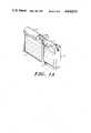
- FIG. 1Ashows a perspective view of a programmable microprocessor-controlled embodiment of the invention.
- FIG. 1Bshows a perspective view of an embodiment similar to that of FIG. 1A.
- FIG. 2shows details of a disposable reservoir, in accordance with the present invention, with the piston and drive member withdrawn.
- FIGS. 2A, 2B and 2Cshow various embodiments of a reservoir safety retaining feature utilizing a lip, barb, or groove.
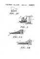
- FIG. 3shows a side view of the piston and drive member, showing the placement of the motor and drivescrew within its contours.
- FIG. 3Ashows a cross-sectional view of the piston member and safety barb.
- FIG. 3Bshows a cross-sectional view of the piston member and the breakaway safety stem.
- FIG. 4shows a perspective view of the piston member, skirt profile and drive engagement threads.
- FIGS. 5A, 5B and 5Cshow different embodiments of the piston face adapted to provide a fluid seal.
- FIG. 6shows a large volume embodiment adapted for sustained bedside infusion.
- FIG. 7shows a section along line 7--7 of FIG. 6, showing the motor and drive.
- FIG. 8shows the embodiment of FIG. 6 having the retaining slide cover.
- FIG. 9shows the large volume pump of FIG. 6 including the housing adapted to house a keyboard, control circuitry and power supply.
- FIG. 1Ashows a perspective view of a complete infusion pump according the present invention, in which a housing 16, containing a power supply and microprocessor control circuity, accomodates a motorized drive unit and a disposable piston/reservoir assembly in its upper portion.
- a keyboard 7, preferably of an impermeable, e.g. membrane-type, constructionis used to enter program information to set a schedule of amounts and timing of medication doses.
- a display 9is used to display the instrument mode, to give instructions for data entry, and to signal certain operator correctable steps and alarm states.
- a reservoir 11In the upper portion of the housing is mounted a reservoir 11 with a centrally disposed elongated piston member 12.
- the reservoir 11is secured at one end by a gentle snap fit within opposing portions of a yoke 15 formed by the housing body. (A single side of yoke 15 is shown in this figure.) At the other end of the reservoir is an axially-sliding cover portion 10 of the housing which overlies the end of the reservoir 11 and bears against the longitudinal portion of piston member 12 to align it. To minimize friction against the piston member 12 as it slides within the reservoir 11, there is provided a protuding longitudinal ridge 122 comprising the area of contact between the piston member and the reservoir 11 and sliding cover 10.
- FIG. 1Bshows a perspective view of a complete infusion unit similar to the embodiment of FIG. 1A and viewed from the opposite side.
- a reservoir 11which may be graduated along its surface, fits into a recess 17 in the unit's housing 16 and is retained by the yoke 15 which varies only slightly from the yoke shown in FIG. 1A.
- the reservoir 11is substantially in the form of a hollow cylinder, and yoke 15 is positioned so as to retain the reservoir in axial alignment. It has been found that the use of the split yoke 15 permits convenient insertion of the reservoir 11 into recess 17. This yoke is located to position the outlet nipple, shown at 29 in FIG.
- FIG. 1BAlso shown in FIG. 1B are the piston member 12, an elongated member with a substantially circular head 13 for hermetically displacing the fluid in the reservoir 11 when driven by the rotating screw drive 14 on the shaft of the drive motor (not visible).
- the housing 16removably holds the reservoir 11 and piston member 12 as a unit.
- the circular piston head 13displaces fluid in the reservoir upon axial motion of the piston member.
- the rearward portion of the piston memberis shaped like a longitudinal segment of cylinder as shown and is preferably internally threaded so that it may be inserted into a position of engagement with drive screw 14.
- Drive screw 14is a finely threaded screw gear, of a diameter to mesh with the internal threads of the piston member 12.
- all of the mechanical elements of the pump and driveare housed in the top portion of the housing 16 and the remainder of housing 16 serves to hold a battery or rechargeable power pack and a microprocessor control and rate selection means for the device.
- a cover 10, shown in phantom,slides in the direction of axis 8 so as to hold the piston member 12 in engagement with the drive screw after the reservoir assembly is inserted in the housing.
- the cover 10may be an integral fixed part of the housing 16, and provided with a slot on the side thereof and longitudinally disposed along axis 8; the slot would be sufficient in size to permit insertion of the piston member 12 when the piston-reservoir assembly is first loaded into the motor assembly.
- the piston member 12After the insertion of the piston member 12 into the slot, the piston member 12 is rotated about axis 8 until the member 12 assumes operating position underneath the cover, where the member 12 may be retained by one or more nubs protruding toward axis 8 from the inside of the cover near the slot. In this manner the cover holds the piston in engagement with the drive screw.
- FIG. 2shows the reservoir 11, with its outlet nipple 29.
- the outlet nipplemay be of any conventional shape such as a taper or bayonet lock, for attachment of a sterile connector fitting 181 and infusion tube 18.
- the nippleWhen used to center the reservoir with respect to a retaining stop as shown at 15 in FIG. 1B the nipple must be of sufficient length so that the stop 15 does not interfere with attachment of the connector fitting.
- the present deviceis intended for use in administering infusions over extended periods of time thus entailing some likelihood of contamination, or incubation of bacterial contaminants. For this reason, it is necessary to guard against misuse, particularly the possibility that reservoir units may be removed and refilled with medication. Such refilling is poor medical practice, and would pose a substantial risk of introducing pyrogenic, infectious or otherwise toxic contaminants into the infusion fluid.
- a safety featurehas been incorporated to prevent withdrawal of the piston and refilling of the reservoir.
- This safety featureincludes a modification to the inner surface contour of the reservoir adjacent to the rear edge 20 of the reservoir, together with a mating modification to the distal end of the piston member.
- Such modifications to the reservoir assemblyare shown in cross-section in FIGS. 2A, 2B, and 2C, and may include a lip 21, a barb 22, or a groove 24 located to engage the piston member and prevent its withdrawal after use.
- the piston memberhas a corresponding barb 32 shown in FIG. 3A projecting radially outward from its distal end which engages the mating portion of the reservoir wall for causing the piston to be locked into the reservoir upon full insertion.
- the piston memberalso has a rounded shoulder 33 preferably extending along each edge of the piston member, to prevent gripping the member which could defeat the safety lock. It has been found that the lip 21 or barb 22 of the reservoir need not protrude more than a few thousandths of an inch above the interior face 23 of the reservoir chamber to be effective, and thus need introduce no unreasonable frictional drag upon the piston member. Frictional drag may be altogether eliminated by use of the groove 24 and barb 32 embodiment of the safety interlock.
- FIG. 3BA further preferred embodiment is shown in FIG. 3B.
- piston face 13is attached to a safety stem 131, which may be integrally formed with face 13, extending through aperture 121 in piston member 12, and holding face 13 to member 12.
- Safety stem 131is capable of transmitting force in either direction along its length, and accordingly to set up and bleed a reservoir it is only necessary to push or pull on stem 131 as for a conventional syringe.
- stem 131With stem 131 intact, it is not possible to place the reservoir into the housing 16 or into engagement with the motor drive gear 14. Accordingly, to mount the assembly for operation, the stem is twisted, breaking off at a narrowed stress point 132, thus removing the obstacle to motor engagement.
- Face 13With the stem thus removed, the face 13 is no longer attached to the piston body 12. It will advance when driven by the piston member, but will remain within the reservoir and will not retract when member 12 is withdrawn. Face 13 may contain a polygonal recess fitted over a corresponding polygonal protrusion of body 12 to prevent face 13 from turning as the stem is twisted to break it away, thus facilitating the breaking away of the safety stem.
- FIG. 3Ashows a longitudinal cross section of one embodiment of the piston member 12, in which 34 is a nub integrally formed with piston member 12 for retaining the front face 13.
- Internal screw threads 31extend the length of the inside face of the piston member back from the front face, culminating in a rounded shoulder, 33 visible at the distal edge.
- On the exterior face of the piston member 12 precisely at the distal end thereofis a slight protrusion 32 which engages the corresponding lip 21, barb 22 or groove 24 shown at FIGS. 2A, 2B, or 2C when the piston has been fully displaced into the reservoir 11, thus preventing removal of the piston or refilling of the reservoir.
- the shoulder 33further discourages gripping of the piston, to safeguard against removal.
- Piston face 13may be a soft neoprene or similar FDA-approved compound, such as is commonly used in the plunger of disposable syringes, which is fitted over a ridged end or bulbous nub at the end of the piston member so as to be controllably moveable thereby.
- the precise mode of attachmentis well known in the art, and accordingly no particular detail of that structure is shown.
- the portion of the piston member 12 which is immediately behind the soft front face 13is substantially circular in cross-section, tapering to a long narrow body, which is shaped substantially like a segment of a cylinder of roughly constant thickness, threaded on the inside.
- the threads 31are shown in cross-section.
- the precise shape of the long cylindrical segmentis not critical so long as the exterior approximately conforms to the inner contour of the reservoir and the segment is not unduly wide or narrow.
- a width of between 1/16 and 3/8 of an inchhas been found to be practical, as it provides good engagement with the drive gear 14, has adequate rigidity and compressive strength to transmit the drive force, and is thin enough to avoid causing frictionally induced motion from the turning of the drive screw gear 14.
- FIG. 3Also shown in FIG. 3.is the screw gear 14 attached to the shaft of motor 35.
- the motorhas its principal cross-sectional dimension less than the diameter of the screw gear, so that it fits entirely within the cylindrical region formed by rotating the piston member 12 about the common central axis of the reservoir/piston assembly.
- An electromagnetic motor having an integral high-ratio gear reduction unit coaxially mounted in a common housing between the motor and drive gearhas been used. This allows the motor 35 to drive the piston member 12 directly via the drive screw gear 14 without requiring other shafts, gears, pulleys, journals or other mechanical coupling or supporting elements in housing 16, resulting in a reduction of both inertial load and frictional losses as compared to conventional pumps.
- the screw gear drivemay be of any appropriate pitch with the choice of pitch dependent on the cross-sectional area of the reservoir, the desired delivery rates and infusion pressures, the available motor speed and torque output and the desired operational cycles.
- the thread profile of the screw gear in relation to the threads of the inner surface of the piston memberis of some importance. In order to reduce backlash in the drive assembly, it is useful either to provide sharp peaks on the drive gear threads, so that the gear bites somewhat into the trenches of the threads of the piston member, or to provide a slight convexity or preloading in the face of the threads of either the drive gear or the piston member.
- the operative metering principle involved in the control system of the present pumpis that rotations of the drive screw 14 are directly proportional to the linear displacement of piston, hence to the volume of medicine delivered.
- the automatic control system for the present pumputilizes an internal light source which is reflected by a segmented optical disc connected to the drive train and detected by a photodetector so as to generate, in a manner known in the art, pulses representative of drive screw rotation.
- the control systemoperates the pump, starting at a predetermined time, and continuing until a predetermined number of pulses have been generated.
- a second photodetectoris provided to detect direct (as opposed to reflected) light from the internal light source; in the event that the second photodetector fails to detect light from the internal light source, the circuitry causes power to be removed from light-drive motor combination.
- the motoris powered and medicine is delivered to the patient only if the motor, the light, and the turn-counting mechanism are all functioning.
- This circuiteliminates the dangers of undetected motor jamming or lamp burnout.
- This peculiar arrangement of the operating components with the logic and condition sensorsnecessarily assures that none of the permutations of component failure can result in a dangerous operating condition, but merely in shut-down of the device.
- FIG. 4there is shown the piston member generally at 12 having internal threads 31 disposed along the length of the piston skirt, the portion of piston member 12 which extends laterally outward from piston head 13 and receives rotating screw gear 14. By engagement with the short rotating screw gear 14 the threads are operative to drive the piston a distance equal to the length of the threads 31. Because the piston skirt must slide laterally into engagement with the drive screw, the skirt comprises not much more, and preferably less, than a semicircumferential portion of the cylindrical surface. In fact, since the piston skirt is used to transmit a linearly-directed drive force, shear forces are negligible; and because the piston head 13 is joined to the skirt portion along an arcuate edge, the skirt may safely be quite narrow.
- FIGS. 5A, 5B and 5CSuch a drive member 12, having a narrow skirt, is shown in FIGS. 5A, 5B and 5C, each of which shows an alternative embodiment of the piston face.
- FIG. 5Athere is shown a piston member having a head 13 in which a circumferential groove holds a sealing ring 54.
- FIG. 5Ba variation of the piston head with sealing ring 54 is shown, further having a flared cup 55.
- the flared cupprovides a strong seal against fluid leakage in the direction opposing the flare.
- piston member 5Cis shown a piston member having an integrally-formed head with a frontal flared cup 55, are a spaced-apart rear portion 56, which, because of its thinness, may be of a large diameter and operate as a bidirectional seal and scraper
- the piston skirt in any of these embodimentspreferably has one or more longitudinal ridges, 122 in FIG. 2, arrayed along its exterior surface, to minimize the area of contact with the reservoir wall and to diminish frictional drag.
- FIG. 6there is shown an embodiment of the present invention usable as a large volume or macro-pump which may be suspended for bedside use in a vertical orientation in a manner similar to a conventional gravity infusion reservoir.
- the reservoir and drive assembly of the macro-pumpare scaled-up versions of the device of FIG. 1, having a housing 66 which accepts a reservoir 61 having a piston drive member 62.
- the reservoiris removably attached to the housing as by lip 68 of the reservoir and circumferential groove 69 in the housing, or by a breech lock or similar arrangement.
- the piston member 62includes a piston face 63, which may be further sealed using an O-ring or any of the structural variations shown in FIGS. 5A, B or C.
- FIG. 7is shown a cutaway view along line 7--7 of the embodiment of FIG. 6, in which a motor 35 and drive screw 14 are shown driveably engaging internal threads of piston member 62.
- FIG. 8further shows a slot in housing 66 for holding piston drive member 62 in alignment. After insertion of the reservoir assembly into the housing a sliding plate 80 may be moved along axis 88 to close the slot and hold the piston drive member 62 in engagement with screw gear 14. Alternate means for biasing the drive assembly are possible.
- FIG. 7shows a drive shaft journalled in the housing, such housing journals are not necessary, and the drive screw assembly may be simply mounted on the motor shaft, and the motor attached to the housing.
- the macro-pump embodimentis readily adaptable to microprocessor drive control and information display in a manner to yield extremely precise dosage control.
- This rigid piston and reservoir configurationeliminates the air space characteristic of bottle reservoirs (which consequently require venting, drip chambers, and other equipment) and the undefined volume characteristic of bag reservoirs (which do not permit ready indication delivered fluid volume), achieving in a single apparatus the precision normally associated with separate, expensive, dosing pumps.
- the housing 66may house both a microprocessor controller and a battery power supply.
- FIG. 9shows such a device, in which the housing 16 includes a keyboard 7 on one face, comprising a small number of programming keys.
- the panelmay incorporate a display similar to 9 of FIG. 1, of a kind known in the art, on which may appear messages to guide an attendant in entering the program data related to reservoir volume, total dose and timing.
- Such a displaymay also display relevant information such as the total delivered dose, or time interval since last infusion, all of which may be conveniently coded, stored and retrieved starting with the basic operating pulse data of the pump drive and the coded program data of the microprocessor control, by techniques known in the art.
- the motorbe an electromagnetic rotary motor capable of continuous operation.
- a stepping motor, or even a solenoid or piezo ratchet driven motorwould be equally serviceable, as long as the device were capable of having its total angular rotation precisely controlled or monitored by the control means.
- a continuous duty rotary motormay prove best for conveniently infusing an initial slug of medication
- a stepping motor or ratchet drivemay prove the most efficient or reliable for sustained infusion of maintenance doses at very low rates.
- a solenoid-actuated ratchet gear and corresponding digital control signalling meansmay be provided in the space shown for the motor.
- the piston memberhas been shown as having a long thin body for simplicity, the relevant structural limitation is that the piston member comprise not much more than about 180° of arc of a cylindrical surface so that it may be conveniently placed in engagement around the drive gear.
- a plurality of suitably spaced elements with internal threads in registry, or a wider piston membercould be employed instead of the single thin piston body shown.
Landscapes
- Health & Medical Sciences (AREA)
- Vascular Medicine (AREA)
- Engineering & Computer Science (AREA)
- Anesthesiology (AREA)
- Biomedical Technology (AREA)
- Heart & Thoracic Surgery (AREA)
- Hematology (AREA)
- Life Sciences & Earth Sciences (AREA)
- Animal Behavior & Ethology (AREA)
- General Health & Medical Sciences (AREA)
- Public Health (AREA)
- Veterinary Medicine (AREA)
- Infusion, Injection, And Reservoir Apparatuses (AREA)
- Sampling And Sample Adjustment (AREA)
Abstract
Description
Claims (7)
Priority Applications (12)
| Application Number | Priority Date | Filing Date | Title |
|---|---|---|---|
| US06/551,851US4648872A (en) | 1983-11-15 | 1983-11-15 | Volumetric pump with replaceable reservoir assembly |
| PCT/US1984/001841WO1985002256A1 (en) | 1983-11-15 | 1984-11-08 | Volumetric pump with replaceable reservoir assembly |
| AT90113244TATE95433T1 (en) | 1983-11-15 | 1984-11-08 | CONTAINER STRUCTURE FOR THE INTERCHANGEABLE CONNECTION WITH A MOTOR DRIVE. |
| JP59504285AJPH0649069B2 (en) | 1983-11-15 | 1984-11-08 | Positive displacement pump with interchangeable container assembly |
| DE90113244TDE3486227T2 (en) | 1983-11-15 | 1984-11-08 | Container structure for the interchangeable connection with a motor drive. |
| DE8484904294TDE3484799D1 (en) | 1983-11-15 | 1984-11-08 | VOLUMETRIC PUMP WITH REPLACEABLE CONTAINER. |
| AT84904294TATE65129T1 (en) | 1983-11-15 | 1984-11-08 | VOLUMETRIC PUMP WITH REPLACEABLE TANK. |
| EP90113244AEP0398394B1 (en) | 1983-11-15 | 1984-11-08 | Reservoir assembly for removable engagement with a motor drive |
| EP84904294AEP0165262B1 (en) | 1983-11-15 | 1984-11-08 | Volumetric pump with replaceable reservoir assembly |
| CA000467495ACA1241231A (en) | 1983-11-15 | 1984-11-09 | Volumetric pump with replaceable reservoir assembly |
| US06/911,398US4749109A (en) | 1983-11-15 | 1986-09-25 | Volumetric pump with replaceable reservoir assembly |
| JP5343110AJPH06315531A (en) | 1983-11-15 | 1993-12-15 | Replaceable container assembly |
Applications Claiming Priority (1)
| Application Number | Priority Date | Filing Date | Title |
|---|---|---|---|
| US06/551,851US4648872A (en) | 1983-11-15 | 1983-11-15 | Volumetric pump with replaceable reservoir assembly |
Related Child Applications (1)
| Application Number | Title | Priority Date | Filing Date |
|---|---|---|---|
| US06/911,398DivisionUS4749109A (en) | 1983-11-15 | 1986-09-25 | Volumetric pump with replaceable reservoir assembly |
Publications (1)
| Publication Number | Publication Date |
|---|---|
| US4648872Atrue US4648872A (en) | 1987-03-10 |
Family
ID=24202940
Family Applications (1)
| Application Number | Title | Priority Date | Filing Date |
|---|---|---|---|
| US06/551,851Expired - LifetimeUS4648872A (en) | 1983-11-15 | 1983-11-15 | Volumetric pump with replaceable reservoir assembly |
Country Status (6)
| Country | Link |
|---|---|
| US (1) | US4648872A (en) |
| EP (1) | EP0165262B1 (en) |
| JP (2) | JPH0649069B2 (en) |
| CA (1) | CA1241231A (en) |
| DE (2) | DE3486227T2 (en) |
| WO (1) | WO1985002256A1 (en) |
Cited By (79)
| Publication number | Priority date | Publication date | Assignee | Title |
|---|---|---|---|---|
| US4832689A (en)* | 1986-11-06 | 1989-05-23 | B. Braun Melsungen Ag | Infusion means |
| EP0416353A1 (en)* | 1989-09-07 | 1991-03-13 | Dieter Dr. Lucas | Syringe |
| US5320503A (en) | 1988-05-17 | 1994-06-14 | Patient Solutions Inc. | Infusion device with disposable elements |
| US5584667A (en) | 1988-05-17 | 1996-12-17 | Davis; David L. | Method of providing uniform flow from an infusion device |
| US5741232A (en)* | 1992-08-17 | 1998-04-21 | Medrad, Inc. | Front loading medical injector and syringe for use therewith |
| US5803712A (en) | 1988-05-17 | 1998-09-08 | Patient Solutions, Inc. | Method of measuring an occlusion in an infusion device with disposable elements |
| US5954697A (en)* | 1998-03-02 | 1999-09-21 | Srisathapat; Chad | Threaded nut syringe plunger for use with a medication infusion pump |
| USD426884S (en)* | 1998-07-08 | 2000-06-20 | Chad Srisathapat | Syringe plunger |
| WO2000047254A1 (en)* | 1999-02-09 | 2000-08-17 | Alaris Medical Systems, Inc. | Directly engaged syringe driver system |
| US6221045B1 (en) | 1995-04-20 | 2001-04-24 | Acist Medical Systems, Inc. | Angiographic injector system with automatic high/low pressure switching |
| CN1082490C (en)* | 1996-10-29 | 2002-04-10 | 希森美康株式会社 | Pump for syringe |
| US6387077B1 (en) | 2000-10-13 | 2002-05-14 | Mallinckrodt Inc. | Apparatus and method for providing a suspended agent |
| US6402718B1 (en) | 1992-08-17 | 2002-06-11 | Medrad, Inc. | Front-loading medical injector and syringe for use therewith |
| US20020165491A1 (en)* | 1999-11-24 | 2002-11-07 | Reilly David M. | Injectors, injector systems, syringes and methods of connecting a syringe to an injector |
| US20020173769A1 (en)* | 2001-05-18 | 2002-11-21 | Gray Larry B. | Infusion set for a fluid pump |
| US20030130618A1 (en)* | 2002-01-04 | 2003-07-10 | Gray Larry B. | Loading mechanism for infusion pump |
| US6652489B2 (en) | 2000-02-07 | 2003-11-25 | Medrad, Inc. | Front-loading medical injector and syringes, syringe interfaces, syringe adapters and syringe plungers for use therewith |
| US20040015137A1 (en)* | 2000-05-18 | 2004-01-22 | Dentsply Research & Development Corp. | Fluid material dispensing syringe |
| US20040019313A1 (en)* | 2002-07-19 | 2004-01-29 | Childers Robert W. | Systems, methods and apparatuses for pumping cassette-based therapies |
| US20040054318A1 (en)* | 2000-12-22 | 2004-03-18 | Langley Christopher Nigel | Pen-type injector having an electronic control unit |
| US20040064041A1 (en)* | 2002-05-30 | 2004-04-01 | Lazzaro Frank A. | Front-loading medical injector and syringes, syringe interfaces, syringe adapters and syringe plungers for use therewith |
| US20040073175A1 (en)* | 2002-01-07 | 2004-04-15 | Jacobson James D. | Infusion system |
| US20050119618A1 (en)* | 2003-04-23 | 2005-06-02 | Gonnelli Robert R. | Hydraulically actuated pump for long duration medicament administration |
| US20050182355A1 (en)* | 2002-01-03 | 2005-08-18 | Tuan Bui | Method and apparatus for providing medical treatment therapy based on calculated demand |
| US20050209563A1 (en)* | 2004-03-19 | 2005-09-22 | Peter Hopping | Cassette-based dialysis medical fluid therapy systems, apparatuses and methods |
| ES2242465A1 (en)* | 2002-08-27 | 2005-11-01 | Zygos Centro Gallego De Reproduccion, S | Portable apparatus for pulsating micro infusion of hormones, has mechanical subsystem including linear thrust mechanism with small gear motor, and control subsystem including angular encoder and programmable micro controller |
| US20050273079A1 (en)* | 2000-10-10 | 2005-12-08 | Hohlfelder Ingrid E | Fluid material dispensing syringe |
| US20060030838A1 (en)* | 2004-07-02 | 2006-02-09 | Gonnelli Robert R | Methods and devices for delivering GLP-1 and uses thereof |
| US20070078380A1 (en)* | 2002-08-12 | 2007-04-05 | Marc Yap | System and method for tension-activated fluid control |
| US20070250010A1 (en)* | 2003-09-18 | 2007-10-25 | Hohlfelder Ingrid E | Fluid material dispensing syringe |
| US20080200868A1 (en)* | 2007-02-15 | 2008-08-21 | One Baxter Parkway | Dialysis system having video display with ambient light adjustment |
| US20080200865A1 (en)* | 2007-02-15 | 2008-08-21 | Baxter International Inc. | Dialysis system having optical flowrate detection |
| US20080200869A1 (en)* | 2007-02-15 | 2008-08-21 | Baxter International Inc. | Dialysis system with efficient battery back-up |
| US7419478B1 (en) | 2003-06-25 | 2008-09-02 | Medrad, Inc. | Front-loading syringe for medical injector having a flexible syringe retaining ring |
| US20090099523A1 (en)* | 2001-05-18 | 2009-04-16 | Grant Kevin L | Infusion pump assembly |
| US20090143735A1 (en)* | 2007-11-30 | 2009-06-04 | Roche Diagnostics Operations, Inc. | Drug reservoir loading and unloading mechanism for a drug delivery device using a unidirectional rotated shaft |
| US20090198174A1 (en)* | 2000-02-10 | 2009-08-06 | Baxter International Inc. | System for monitoring and controlling peritoneal dialysis |
| US20090240232A1 (en)* | 2006-03-30 | 2009-09-24 | Vakerutas,Llc | Multi-cartridge fluid delivery device |
| US20090250491A1 (en)* | 2006-09-08 | 2009-10-08 | A.C. Dispensing Equipment, Inc. | Cartridge based fluid dispensing apparatus |
| US20090281484A1 (en)* | 2003-10-28 | 2009-11-12 | Baxter International Inc. | Peritoneal dialysis machine |
| US20100089475A1 (en)* | 2008-10-10 | 2010-04-15 | Tracey Brian D | Medium connector |
| US20100094222A1 (en)* | 2008-10-10 | 2010-04-15 | Grant Kevin L | Infusion pump assembly |
| US20100094215A1 (en)* | 2008-10-10 | 2010-04-15 | Grant Kevin L | Pump assembly with a removable cover assembly |
| US7731689B2 (en) | 2007-02-15 | 2010-06-08 | Baxter International Inc. | Dialysis system having inductive heating |
| US20100206901A1 (en)* | 2007-09-01 | 2010-08-19 | Jost-Werke Gmbh | Filling system for the metered delivery of a lubricant |
| US20100331786A1 (en)* | 2009-06-01 | 2010-12-30 | Sanofi-Aventis Deutschland Gmbh | Spindle and bearing combination and drug delivery device |
| US20110009825A1 (en)* | 2009-07-08 | 2011-01-13 | Medtronic Minimed, Inc. | Reservoir filling systems and methods |
| US20110009823A1 (en)* | 2009-07-08 | 2011-01-13 | Chong Colin A | Reservoir filling systems and methods |
| US20110040244A1 (en)* | 2002-05-24 | 2011-02-17 | Baxter International Inc. | Automated dialysis system including a piston and stepper motor |
| US8066672B2 (en) | 2008-10-10 | 2011-11-29 | Deka Products Limited Partnership | Infusion pump assembly with a backup power supply |
| US8223028B2 (en) | 2008-10-10 | 2012-07-17 | Deka Products Limited Partnership | Occlusion detection system and method |
| US8267892B2 (en) | 2008-10-10 | 2012-09-18 | Deka Products Limited Partnership | Multi-language / multi-processor infusion pump assembly |
| US8558964B2 (en) | 2007-02-15 | 2013-10-15 | Baxter International Inc. | Dialysis system having display with electromagnetic compliance (“EMC”) seal |
| US8992462B2 (en) | 2002-07-19 | 2015-03-31 | Baxter International Inc. | Systems and methods for performing peritoneal dialysis |
| US20150196452A1 (en)* | 2014-01-10 | 2015-07-16 | Sebacia, Inc. | Particle containers and delivery applicators |
| US9108047B2 (en) | 2010-06-04 | 2015-08-18 | Bayer Medical Care Inc. | System and method for planning and monitoring multi-dose radiopharmaceutical usage on radiopharmaceutical injectors |
| US9180245B2 (en) | 2008-10-10 | 2015-11-10 | Deka Products Limited Partnership | System and method for administering an infusible fluid |
| US9480797B1 (en) | 2015-10-28 | 2016-11-01 | Bayer Healthcare Llc | System and method for syringe plunger engagement with an injector |
| US9675744B2 (en) | 2002-05-24 | 2017-06-13 | Baxter International Inc. | Method of operating a disposable pumping unit |
| US9694131B2 (en) | 2003-11-25 | 2017-07-04 | Bayer Healthcare Llc | Medical injector system |
| US9744305B2 (en) | 2012-09-28 | 2017-08-29 | Bayer Healthcare Llc | Quick release plunger |
| US9844622B2 (en) | 2000-07-10 | 2017-12-19 | Bayer Healthcare Llc | Syringes for medical injector systems |
| US9855390B2 (en) | 2006-03-15 | 2018-01-02 | Bayer Healthcare Llc | Plunger covers and plungers for use in syringes |
| USD829434S1 (en)* | 2016-04-29 | 2018-10-02 | Csl Behring Recombinant Facility Ag | Syringe pump housing |
| USD831194S1 (en)* | 2016-04-29 | 2018-10-16 | Csl Behring Recombinant Facility Ag | Syringe pump housing |
| USD831820S1 (en)* | 2016-04-29 | 2018-10-23 | Csl Behring Recombinant Facility Ag | Syringe pump housing |
| USD831821S1 (en)* | 2016-04-29 | 2018-10-23 | Csl Behring Recombinant Facility Ag | Syringe pump housing |
| USD847985S1 (en) | 2007-03-14 | 2019-05-07 | Bayer Healthcare Llc | Syringe plunger cover |
| US10806852B2 (en) | 2014-03-19 | 2020-10-20 | Bayer Healthcare Llc | System for syringe engagement to an injector |
| CN112512607A (en)* | 2018-08-01 | 2021-03-16 | B·布莱恩·梅尔松根股份公司 | Infusion system with infusion pump and pump module connectable thereto |
| US11179516B2 (en) | 2017-06-22 | 2021-11-23 | Baxter International Inc. | Systems and methods for incorporating patient pressure into medical fluid delivery |
| USD942005S1 (en) | 2007-03-14 | 2022-01-25 | Bayer Healthcare Llc | Orange syringe plunger cover |
| USD1002840S1 (en) | 2007-03-14 | 2023-10-24 | Bayer Healthcare Llc | Syringe plunger |
| US11883636B2 (en) | 2018-02-27 | 2024-01-30 | Bayer Healthcare Llc | Syringe plunger engagement mechanism |
| US11969582B2 (en) | 2017-01-06 | 2024-04-30 | Bayer Healthcare Llc | Syringe plunger with dynamic seal |
| US11998718B2 (en) | 2020-06-18 | 2024-06-04 | Bayer Healthcare Llc | System and method for syringe plunger engagement with an injector |
| USD1031029S1 (en) | 2003-11-25 | 2024-06-11 | Bayer Healthcare Llc | Syringe plunger |
| US12186531B2 (en) | 2008-10-10 | 2025-01-07 | Deka Products Limited Partnership | Infusion pump assembly |
| US12370327B2 (en) | 2008-10-10 | 2025-07-29 | Deka Products Limited Partnership | Infusion pump methods, systems and apparatus |
Families Citing this family (18)
| Publication number | Priority date | Publication date | Assignee | Title |
|---|---|---|---|---|
| US5097122A (en)* | 1990-04-16 | 1992-03-17 | Pacesetter Infusion, Ltd. | Medication infusion system having optical motion sensor to detect drive mechanism malfunction |
| US6663602B2 (en) | 2000-06-16 | 2003-12-16 | Novo Nordisk A/S | Injection device |
| AU2001289589A1 (en) | 2000-09-22 | 2002-04-02 | Novo-Nordisk A/S | A medication delivery device |
| ATE444090T1 (en) | 2004-10-21 | 2009-10-15 | Novo Nordisk As | SELECTION MECHANISM FOR A ROTARY PIN |
| US7353608B2 (en)* | 2006-01-25 | 2008-04-08 | Custom Sensors & Technologies, Inc. | Multiple channel RVDT with dual load path and fail-safe mechanism |
| CN101405044B (en) | 2006-03-20 | 2013-10-16 | 诺沃-诺迪斯克有限公司 | Determination of position of injection needle |
| ATE458517T1 (en) | 2006-05-16 | 2010-03-15 | Novo Nordisk As | TRANSMISSION MECHANISM FOR AN INJECTION DEVICE |
| US20070270750A1 (en)* | 2006-05-17 | 2007-11-22 | Alcon, Inc. | Drug delivery device |
| JP5253387B2 (en) | 2006-05-18 | 2013-07-31 | ノボ・ノルデイスク・エー/エス | Injection device with mode locking means |
| US8052655B2 (en) | 2006-09-29 | 2011-11-08 | Novo Nordisk A/S | Injection device with electronic detecting means |
| US9108006B2 (en) | 2007-08-17 | 2015-08-18 | Novo Nordisk A/S | Medical device with value sensor |
| CA2739185C (en)* | 2007-09-28 | 2015-12-22 | Calibra Medical, Inc. | Disposable infusion device with reuse lock-out |
| CA2707820A1 (en) | 2007-12-31 | 2009-07-09 | Novo Nordisk A/S | Electronically monitored injection device |
| US9295776B2 (en)* | 2008-04-11 | 2016-03-29 | Medtronic Minimed, Inc. | Reservoir plunger head systems and methods |
| US8206353B2 (en) | 2008-04-11 | 2012-06-26 | Medtronic Minimed, Inc. | Reservoir barrier layer systems and methods |
| US8858501B2 (en) | 2008-04-11 | 2014-10-14 | Medtronic Minimed, Inc. | Reservoir barrier layer systems and methods |
| JP6069351B2 (en) | 2011-12-29 | 2017-02-01 | ノボ・ノルデイスク・エー/エス | Torsion spring type automatic syringe with dial-up / dial-down administration mechanism |
| US11577028B2 (en)* | 2021-01-20 | 2023-02-14 | Becton, Dickinson And Company | Syringe with a bidirectional plunger advancing mechanism for a micro-dosing syringe pump |
Citations (35)
| Publication number | Priority date | Publication date | Assignee | Title |
|---|---|---|---|---|
| US996128A (en)* | 1910-07-18 | 1911-06-27 | Joseph Payne | Power-syringe. |
| US2602446A (en)* | 1950-02-27 | 1952-07-08 | Antonina S Glass | Automatic medical injection apparatus |
| US2627270A (en)* | 1946-02-09 | 1953-02-03 | Antonina S Glass | Self-propelled automatic syringe |
| US2627999A (en)* | 1949-04-22 | 1953-02-10 | Ernest W Swan | Combined holder and dispenser for tube contained materials |
| US2725877A (en)* | 1950-12-22 | 1955-12-06 | Reiter David | Hypodermic syringe with feed control |
| US2734504A (en)* | 1956-02-14 | Hypodermic injection devices | ||
| US3155090A (en)* | 1962-01-10 | 1964-11-03 | Holter Company | Hypodermic syringe operating means |
| US3156236A (en)* | 1961-12-07 | 1964-11-10 | Cordis Corp | Medical injector |
| US3395704A (en)* | 1964-11-19 | 1968-08-06 | Frey Max | Power operated syringe |
| US3456649A (en)* | 1965-12-03 | 1969-07-22 | Warren R Jewett | Motor driven fluid administration apparatus |
| US3623474A (en)* | 1966-07-25 | 1971-11-30 | Medrad Inc | Angiographic injection equipment |
| US3631847A (en)* | 1966-03-04 | 1972-01-04 | James C Hobbs | Method and apparatus for injecting fluid into the vascular system |
| US3701345A (en)* | 1970-09-29 | 1972-10-31 | Medrad Inc | Angiographic injector equipment |
| US3771694A (en)* | 1972-07-07 | 1973-11-13 | A Kaminski | Infusion pump |
| US3790048A (en)* | 1972-07-28 | 1974-02-05 | Ortho Pharma Corp | Incremental dose dispenser |
| US3811442A (en)* | 1972-03-23 | 1974-05-21 | A Maroth | Hypodermic syringe holder and applicator |
| US3812843A (en)* | 1973-03-12 | 1974-05-28 | Lear Siegler Inc | Method and apparatus for injecting contrast media into the vascular system |
| US3858581A (en)* | 1973-07-02 | 1975-01-07 | Dean Kamen | Medication injection device |
| US3880138A (en)* | 1973-03-12 | 1975-04-29 | Lear Siegler Inc | Method for injecting contrast media into the vascular system |
| US3886938A (en)* | 1973-10-23 | 1975-06-03 | Scala Anthony | Power operated fluid infusion device |
| US4059110A (en)* | 1976-10-07 | 1977-11-22 | Timex Corporation | Clockwork driven hypodermic syringe |
| US4073321A (en)* | 1976-03-15 | 1978-02-14 | George Moskowitz | Adjustable blocking means for dosage regulation |
| US4108177A (en)* | 1976-04-23 | 1978-08-22 | Michel Louis Paul Pistor | Automatic injector device |
| US4126132A (en)* | 1975-07-28 | 1978-11-21 | Andros Incorporated | Intravenous and intra arterial delivery system |
| US4142524A (en)* | 1977-06-02 | 1979-03-06 | Andros Incorporated | Cassette for intravenous delivery system |
| US4150672A (en)* | 1976-11-12 | 1979-04-24 | Martin John K | Injection device and method |
| US4191187A (en)* | 1977-03-09 | 1980-03-04 | National Research Development Corporation | Medical apparatus |
| US4258866A (en)* | 1977-06-20 | 1981-03-31 | Bergman Carl P | Dispenser actuating chuck adapter |
| US4269185A (en)* | 1979-01-08 | 1981-05-26 | Whitney Douglass G | Self contained mechanical injector |
| US4300554A (en)* | 1979-02-22 | 1981-11-17 | Intermedicat Gmbh | Portable infusion apparatus |
| US4367738A (en)* | 1981-10-28 | 1983-01-11 | Janssen Pharmaceutica Inc. | Pre-filled syringe for abusable drugs |
| US4391272A (en)* | 1978-03-10 | 1983-07-05 | Tulcea, S.A. | Disposable syringe |
| US4399712A (en)* | 1981-02-09 | 1983-08-23 | Nichiryo Co., Ltd. | Semi-automatic electro-mechanical pipette with controlled tip remover |
| US4465475A (en)* | 1981-12-21 | 1984-08-14 | Intermedicat Gmbh | Injector for medical uses |
| US4493704A (en)* | 1982-11-29 | 1985-01-15 | Oximetrix, Inc. | Portable fluid infusion apparatus |
Family Cites Families (7)
| Publication number | Priority date | Publication date | Assignee | Title |
|---|---|---|---|---|
| JPS4513775Y1 (en)* | 1969-03-25 | 1970-06-12 | ||
| JPS5136546U (en)* | 1974-09-07 | 1976-03-18 | ||
| US3995156A (en)* | 1975-03-25 | 1976-11-30 | Quick-Rotan Becker & Notz Kg | Transmitter for governed-speed drives employing an optical grating and photocells at an angle thereto |
| USRE31608E (en)* | 1977-01-21 | 1984-06-19 | Altex Scientific, Inc. | Fluid pump mechanism |
| JPS54102226A (en)* | 1978-01-31 | 1979-08-11 | Kobe Steel Ltd | Copper alloy for deep drawing |
| DE2848612C2 (en)* | 1978-11-09 | 1981-05-27 | Pfaff Haushaltsmaschinen GmbH, 7500 Karlsruhe | Pulse generator of a sewing machine drive |
| US4470698A (en)* | 1982-05-13 | 1984-09-11 | The United States Of America As Represented By The Secretary Of The Army | Programmable scanner/tracker |
- 1983
- 1983-11-15USUS06/551,851patent/US4648872A/ennot_activeExpired - Lifetime
- 1984
- 1984-11-08JPJP59504285Apatent/JPH0649069B2/ennot_activeExpired - Lifetime
- 1984-11-08DEDE90113244Tpatent/DE3486227T2/ennot_activeExpired - Fee Related
- 1984-11-08WOPCT/US1984/001841patent/WO1985002256A1/enactiveIP Right Grant
- 1984-11-08EPEP84904294Apatent/EP0165262B1/ennot_activeExpired
- 1984-11-08DEDE8484904294Tpatent/DE3484799D1/ennot_activeExpired - Lifetime
- 1984-11-09CACA000467495Apatent/CA1241231A/ennot_activeExpired
- 1993
- 1993-12-15JPJP5343110Apatent/JPH06315531A/enactivePending
Patent Citations (38)
| Publication number | Priority date | Publication date | Assignee | Title |
|---|---|---|---|---|
| US2734504A (en)* | 1956-02-14 | Hypodermic injection devices | ||
| US996128A (en)* | 1910-07-18 | 1911-06-27 | Joseph Payne | Power-syringe. |
| US2627270A (en)* | 1946-02-09 | 1953-02-03 | Antonina S Glass | Self-propelled automatic syringe |
| US2627999A (en)* | 1949-04-22 | 1953-02-10 | Ernest W Swan | Combined holder and dispenser for tube contained materials |
| US2602446A (en)* | 1950-02-27 | 1952-07-08 | Antonina S Glass | Automatic medical injection apparatus |
| US2725877A (en)* | 1950-12-22 | 1955-12-06 | Reiter David | Hypodermic syringe with feed control |
| US3156236A (en)* | 1961-12-07 | 1964-11-10 | Cordis Corp | Medical injector |
| US3155090A (en)* | 1962-01-10 | 1964-11-03 | Holter Company | Hypodermic syringe operating means |
| US3395704A (en)* | 1964-11-19 | 1968-08-06 | Frey Max | Power operated syringe |
| US3456649A (en)* | 1965-12-03 | 1969-07-22 | Warren R Jewett | Motor driven fluid administration apparatus |
| US3631847A (en)* | 1966-03-04 | 1972-01-04 | James C Hobbs | Method and apparatus for injecting fluid into the vascular system |
| US3623474A (en)* | 1966-07-25 | 1971-11-30 | Medrad Inc | Angiographic injection equipment |
| US3701345A (en)* | 1970-09-29 | 1972-10-31 | Medrad Inc | Angiographic injector equipment |
| US3811442A (en)* | 1972-03-23 | 1974-05-21 | A Maroth | Hypodermic syringe holder and applicator |
| US3771694A (en)* | 1972-07-07 | 1973-11-13 | A Kaminski | Infusion pump |
| US3790048A (en)* | 1972-07-28 | 1974-02-05 | Ortho Pharma Corp | Incremental dose dispenser |
| US3880138A (en)* | 1973-03-12 | 1975-04-29 | Lear Siegler Inc | Method for injecting contrast media into the vascular system |
| US3812843A (en)* | 1973-03-12 | 1974-05-28 | Lear Siegler Inc | Method and apparatus for injecting contrast media into the vascular system |
| US3858581A (en)* | 1973-07-02 | 1975-01-07 | Dean Kamen | Medication injection device |
| US3886938A (en)* | 1973-10-23 | 1975-06-03 | Scala Anthony | Power operated fluid infusion device |
| US4126132A (en)* | 1975-07-28 | 1978-11-21 | Andros Incorporated | Intravenous and intra arterial delivery system |
| US4073321A (en)* | 1976-03-15 | 1978-02-14 | George Moskowitz | Adjustable blocking means for dosage regulation |
| US4108177A (en)* | 1976-04-23 | 1978-08-22 | Michel Louis Paul Pistor | Automatic injector device |
| US4059110A (en)* | 1976-10-07 | 1977-11-22 | Timex Corporation | Clockwork driven hypodermic syringe |
| US4150672A (en)* | 1976-11-12 | 1979-04-24 | Martin John K | Injection device and method |
| US4191187A (en)* | 1977-03-09 | 1980-03-04 | National Research Development Corporation | Medical apparatus |
| US4142524A (en)* | 1977-06-02 | 1979-03-06 | Andros Incorporated | Cassette for intravenous delivery system |
| US4258866A (en)* | 1977-06-20 | 1981-03-31 | Bergman Carl P | Dispenser actuating chuck adapter |
| US4391272A (en)* | 1978-03-10 | 1983-07-05 | Tulcea, S.A. | Disposable syringe |
| US4269185A (en)* | 1979-01-08 | 1981-05-26 | Whitney Douglass G | Self contained mechanical injector |
| US4320757A (en)* | 1979-01-08 | 1982-03-23 | Whitney Douglass G | Self contained injection system |
| US4326517A (en)* | 1979-01-08 | 1982-04-27 | Whitney Douglass G | Self contained injection system |
| US4342311A (en)* | 1979-01-08 | 1982-08-03 | Whitney Douglass G | Injector with programming means |
| US4300554A (en)* | 1979-02-22 | 1981-11-17 | Intermedicat Gmbh | Portable infusion apparatus |
| US4399712A (en)* | 1981-02-09 | 1983-08-23 | Nichiryo Co., Ltd. | Semi-automatic electro-mechanical pipette with controlled tip remover |
| US4367738A (en)* | 1981-10-28 | 1983-01-11 | Janssen Pharmaceutica Inc. | Pre-filled syringe for abusable drugs |
| US4465475A (en)* | 1981-12-21 | 1984-08-14 | Intermedicat Gmbh | Injector for medical uses |
| US4493704A (en)* | 1982-11-29 | 1985-01-15 | Oximetrix, Inc. | Portable fluid infusion apparatus |
Cited By (209)
| Publication number | Priority date | Publication date | Assignee | Title |
|---|---|---|---|---|
| US4832689A (en)* | 1986-11-06 | 1989-05-23 | B. Braun Melsungen Ag | Infusion means |
| US6146109A (en) | 1988-05-17 | 2000-11-14 | Alaris Medical Systems, Inc. | Infusion device with disposable elements |
| US5320503A (en) | 1988-05-17 | 1994-06-14 | Patient Solutions Inc. | Infusion device with disposable elements |
| US5584667A (en) | 1988-05-17 | 1996-12-17 | Davis; David L. | Method of providing uniform flow from an infusion device |
| US5803712A (en) | 1988-05-17 | 1998-09-08 | Patient Solutions, Inc. | Method of measuring an occlusion in an infusion device with disposable elements |
| US20080015506A1 (en)* | 1988-05-17 | 2008-01-17 | Davis David L | Infusion device with disposable elements |
| US20050013698A1 (en)* | 1988-05-17 | 2005-01-20 | Davis David Lyle | Infusion device with disposable elements |
| US6742992B2 (en) | 1988-05-17 | 2004-06-01 | I-Flow Corporation | Infusion device with disposable elements |
| US6312227B1 (en) | 1988-05-17 | 2001-11-06 | I-Flow Corp. | Infusion device with disposable elements |
| EP0416353A1 (en)* | 1989-09-07 | 1991-03-13 | Dieter Dr. Lucas | Syringe |
| US6733478B2 (en) | 1992-08-17 | 2004-05-11 | Medrad, Inc. | System and method for providing information from a syringe to an injector |
| US6562008B1 (en) | 1992-08-17 | 2003-05-13 | Medrad, Inc. | Front loading medical injector and syringe for use therewith |
| US6808513B2 (en) | 1992-08-17 | 2004-10-26 | Medrad, Inc. | Front loading medical injector and syringe for use therewith |
| US6090064A (en)* | 1992-08-17 | 2000-07-18 | Medrad, Inc. | Front loading medical injector and syringe for use therewith |
| US5997502A (en)* | 1992-08-17 | 1999-12-07 | Medrad, Inc. | Front loading medical injector and syringe for use therewith |
| US20050059932A1 (en)* | 1992-08-17 | 2005-03-17 | Reilly David M. | Injector system having a front loading pressure jacket assembly |
| US6402718B1 (en) | 1992-08-17 | 2002-06-11 | Medrad, Inc. | Front-loading medical injector and syringe for use therewith |
| US6402717B1 (en) | 1992-08-17 | 2002-06-11 | Medrad, Inc. | Front-loading medical injector and syringe for use therewith |
| US6475192B1 (en) | 1992-08-17 | 2002-11-05 | Medrad, Inc. | System and method for providing information from a syringe to an injector |
| US5741232A (en)* | 1992-08-17 | 1998-04-21 | Medrad, Inc. | Front loading medical injector and syringe for use therewith |
| US7081105B2 (en) | 1992-08-17 | 2006-07-25 | Medrad, Inc. | Injector system having a front loading pressure jacket assembly |
| US6221045B1 (en) | 1995-04-20 | 2001-04-24 | Acist Medical Systems, Inc. | Angiographic injector system with automatic high/low pressure switching |
| CN1082490C (en)* | 1996-10-29 | 2002-04-10 | 希森美康株式会社 | Pump for syringe |
| US5954697A (en)* | 1998-03-02 | 1999-09-21 | Srisathapat; Chad | Threaded nut syringe plunger for use with a medication infusion pump |
| USD426884S (en)* | 1998-07-08 | 2000-06-20 | Chad Srisathapat | Syringe plunger |
| EP1457220A3 (en)* | 1999-02-09 | 2005-12-07 | ALARIS Medical Systems, Inc. | Directly engaged syringe driver system |
| WO2000047254A1 (en)* | 1999-02-09 | 2000-08-17 | Alaris Medical Systems, Inc. | Directly engaged syringe driver system |
| US20040049161A1 (en)* | 1999-02-09 | 2004-03-11 | Shearn James G. J. | Directly engaged syringe driver system |
| US7338472B2 (en) | 1999-02-09 | 2008-03-04 | Cardinal Health 303, Inc. | Directly engaged syringe driver system |
| US20080154203A1 (en)* | 1999-02-09 | 2008-06-26 | Cardinal Health 303, Inc. | Directly engaged syringe driver system |
| US6645177B1 (en) | 1999-02-09 | 2003-11-11 | Alaris Medical Systems, Inc. | Directly engaged syringe driver system |
| AU2004205142B2 (en)* | 1999-02-09 | 2007-11-22 | Carefusion 303, Inc. | Directly engaged syringe driver system |
| AU772647B2 (en)* | 1999-02-09 | 2004-05-06 | Carefusion 303, Inc. | Directly engaged syringe driver system |
| US7972306B2 (en) | 1999-02-09 | 2011-07-05 | Carefusion 303, Inc. | Directly engaged syringe driver system |
| US20020165491A1 (en)* | 1999-11-24 | 2002-11-07 | Reilly David M. | Injectors, injector systems, syringes and methods of connecting a syringe to an injector |
| US20040068223A1 (en)* | 1999-11-24 | 2004-04-08 | Reilly David M. | Injector system including an injector drive member that automatically advances and engages a syringe plunger |
| US7029459B2 (en) | 1999-11-24 | 2006-04-18 | Medrad, Inc. | Injector system including a powered loading device for connecting a syringe to an injector |
| US7465290B2 (en) | 1999-11-24 | 2008-12-16 | Medrad, Inc. | Injector system including an injector drive member that automatically advances and engages a syringe plunger |
| US6958053B1 (en) | 1999-11-24 | 2005-10-25 | Medrad, Inc. | Injector providing drive member advancement and engagement with syringe plunger, and method of connecting a syringe to an injector |
| US20040133161A1 (en)* | 2000-02-07 | 2004-07-08 | Mark Trocki | Front-loading syringe adapted to releasably engage a medical injector regardless of the orientation of the syringe with respect to the injector |
| US20040133153A1 (en)* | 2000-02-07 | 2004-07-08 | Mark Trocki | Syringe adapter for use with a medical injector and method for adapting an injector |
| US20040133162A1 (en)* | 2000-02-07 | 2004-07-08 | Mark Trocki | Front-loading medical injector adapted to releasably engage a syringe regardless of the orientation of the syringe with respect to the injector |
| US7540856B2 (en) | 2000-02-07 | 2009-06-02 | Medrad, Inc. | Front-loading medical injector adapted to releasably engage a syringe regardless of the orientation of the syringe with respect to the injector |
| US6652489B2 (en) | 2000-02-07 | 2003-11-25 | Medrad, Inc. | Front-loading medical injector and syringes, syringe interfaces, syringe adapters and syringe plungers for use therewith |
| US8721596B2 (en) | 2000-02-07 | 2014-05-13 | Bayer Medical Care Inc. | Front-loading syringe adapted to releasably engage a medical injector regardless of the orientation of the syringe with respect to the injector |
| US9636452B2 (en) | 2000-02-07 | 2017-05-02 | Bayer Healthcare Llc | Front-loading medical injector adapted to releasably engage a syringe regardless of the orientation of the syringe with respect to the injector |
| US8172789B2 (en) | 2000-02-10 | 2012-05-08 | Baxter International Inc. | Peritoneal dialysis system having cassette-based-pressure-controlled pumping |
| US9474842B2 (en) | 2000-02-10 | 2016-10-25 | Baxter International Inc. | Method and apparatus for monitoring and controlling peritoneal dialysis therapy |
| US20090198174A1 (en)* | 2000-02-10 | 2009-08-06 | Baxter International Inc. | System for monitoring and controlling peritoneal dialysis |
| US8323231B2 (en) | 2000-02-10 | 2012-12-04 | Baxter International, Inc. | Method and apparatus for monitoring and controlling peritoneal dialysis therapy |
| US8206339B2 (en) | 2000-02-10 | 2012-06-26 | Baxter International Inc. | System for monitoring and controlling peritoneal dialysis |
| US10322224B2 (en) | 2000-02-10 | 2019-06-18 | Baxter International Inc. | Apparatus and method for monitoring and controlling a peritoneal dialysis therapy |
| US20110028892A1 (en)* | 2000-02-10 | 2011-02-03 | Baxter International Inc. | Peritoneal dialysis system having cassette-based-pressure-controlled pumping |
| US20050101913A1 (en)* | 2000-05-18 | 2005-05-12 | Hohlfelder Ingrid E. | Fluid material dispensing syringe |
| US20040015137A1 (en)* | 2000-05-18 | 2004-01-22 | Dentsply Research & Development Corp. | Fluid material dispensing syringe |
| US9844622B2 (en) | 2000-07-10 | 2017-12-19 | Bayer Healthcare Llc | Syringes for medical injector systems |
| US20050273079A1 (en)* | 2000-10-10 | 2005-12-08 | Hohlfelder Ingrid E | Fluid material dispensing syringe |
| US6387077B1 (en) | 2000-10-13 | 2002-05-14 | Mallinckrodt Inc. | Apparatus and method for providing a suspended agent |
| US20040054318A1 (en)* | 2000-12-22 | 2004-03-18 | Langley Christopher Nigel | Pen-type injector having an electronic control unit |
| US8926553B2 (en) | 2000-12-22 | 2015-01-06 | Christopher Nigel Langley | Pen-type injector having an electronic control unit |
| US9173996B2 (en) | 2001-05-18 | 2015-11-03 | Deka Products Limited Partnership | Infusion set for a fluid pump |
| US20070049870A1 (en)* | 2001-05-18 | 2007-03-01 | Deka Products Limited Partnership | Infusion Set for a Fluid Pump |
| US20020173769A1 (en)* | 2001-05-18 | 2002-11-21 | Gray Larry B. | Infusion set for a fluid pump |
| US8034026B2 (en) | 2001-05-18 | 2011-10-11 | Deka Products Limited Partnership | Infusion pump assembly |
| US20090099523A1 (en)* | 2001-05-18 | 2009-04-16 | Grant Kevin L | Infusion pump assembly |
| US8545435B2 (en) | 2002-01-03 | 2013-10-01 | Baxter International, Inc. | Method and apparatus for providing medical treatment therapy based on calculated demand |
| US20050182355A1 (en)* | 2002-01-03 | 2005-08-18 | Tuan Bui | Method and apparatus for providing medical treatment therapy based on calculated demand |
| US20030130618A1 (en)* | 2002-01-04 | 2003-07-10 | Gray Larry B. | Loading mechanism for infusion pump |
| US7306578B2 (en)* | 2002-01-04 | 2007-12-11 | Deka Products Limited Partnership | Loading mechanism for infusion pump |
| US20040073175A1 (en)* | 2002-01-07 | 2004-04-15 | Jacobson James D. | Infusion system |
| US9511180B2 (en) | 2002-05-24 | 2016-12-06 | Baxter International Inc. | Stepper motor driven peritoneal dialysis machine |
| US8376999B2 (en) | 2002-05-24 | 2013-02-19 | Baxter International Inc. | Automated dialysis system including touch screen controlled mechanically and pneumatically actuated pumping |
| US9744283B2 (en) | 2002-05-24 | 2017-08-29 | Baxter International Inc. | Automated dialysis system using piston and negative pressure |
| US8075526B2 (en) | 2002-05-24 | 2011-12-13 | Baxter International Inc. | Automated dialysis system including a piston and vacuum source |
| US9675744B2 (en) | 2002-05-24 | 2017-06-13 | Baxter International Inc. | Method of operating a disposable pumping unit |
| US20110040244A1 (en)* | 2002-05-24 | 2011-02-17 | Baxter International Inc. | Automated dialysis system including a piston and stepper motor |
| US8529496B2 (en) | 2002-05-24 | 2013-09-10 | Baxter International Inc. | Peritoneal dialysis machine touch screen user interface |
| US9775939B2 (en) | 2002-05-24 | 2017-10-03 | Baxter International Inc. | Peritoneal dialysis systems and methods having graphical user interface |
| US8066671B2 (en) | 2002-05-24 | 2011-11-29 | Baxter International Inc. | Automated dialysis system including a piston and stepper motor |
| US10137235B2 (en) | 2002-05-24 | 2018-11-27 | Baxter International Inc. | Automated peritoneal dialysis system using stepper motor |
| US8506522B2 (en) | 2002-05-24 | 2013-08-13 | Baxter International Inc. | Peritoneal dialysis machine touch screen user interface |
| US10751457B2 (en) | 2002-05-24 | 2020-08-25 | Baxter International Inc. | Systems with disposable pumping unit |
| US8684971B2 (en) | 2002-05-24 | 2014-04-01 | Baxter International Inc. | Automated dialysis system using piston and negative pressure |
| US20090312632A1 (en)* | 2002-05-30 | 2009-12-17 | Medrad, Inc. | Syringe plunger sensing mechanism for a medical injector |
| US8133203B2 (en) | 2002-05-30 | 2012-03-13 | Medrad, Inc. | Method of injecting fluids from a dual syringe injector system |
| US20040064041A1 (en)* | 2002-05-30 | 2004-04-01 | Lazzaro Frank A. | Front-loading medical injector and syringes, syringe interfaces, syringe adapters and syringe plungers for use therewith |
| US7553294B2 (en) | 2002-05-30 | 2009-06-30 | Medrad, Inc. | Syringe plunger sensing mechanism for a medical injector |
| US8574200B2 (en) | 2002-05-30 | 2013-11-05 | Medrad, Inc. | Dual syringe injector system |
| US8740837B2 (en) | 2002-07-19 | 2014-06-03 | Baxter International Inc. | Pumping systems for cassette-based dialysis |
| US7238164B2 (en) | 2002-07-19 | 2007-07-03 | Baxter International Inc. | Systems, methods and apparatuses for pumping cassette-based therapies |
| US9795729B2 (en) | 2002-07-19 | 2017-10-24 | Baxter International Inc. | Pumping systems for cassette-based dialysis |
| US8740836B2 (en) | 2002-07-19 | 2014-06-03 | Baxter International Inc. | Pumping systems for cassette-based dialysis |
| US8679054B2 (en) | 2002-07-19 | 2014-03-25 | Baxter International Inc. | Pumping systems for cassette-based dialysis |
| US9283312B2 (en) | 2002-07-19 | 2016-03-15 | Baxter International Inc. | Dialysis system and method for cassette-based pumping and valving |
| US20040019313A1 (en)* | 2002-07-19 | 2004-01-29 | Childers Robert W. | Systems, methods and apparatuses for pumping cassette-based therapies |
| US11020519B2 (en) | 2002-07-19 | 2021-06-01 | Baxter International Inc. | Systems and methods for performing peritoneal dialysis |
| US10525184B2 (en) | 2002-07-19 | 2020-01-07 | Baxter International Inc. | Dialysis system and method for pumping and valving according to flow schedule |
| US8992462B2 (en) | 2002-07-19 | 2015-03-31 | Baxter International Inc. | Systems and methods for performing peritoneal dialysis |
| US20110106003A1 (en)* | 2002-07-19 | 2011-05-05 | Baxter International Inc. | Dialysis system and method for cassette-based pumping and valving |
| US7527608B2 (en) | 2002-08-12 | 2009-05-05 | Lma North America, Inc. | Medication infusion and aspiration system and method |
| US20090182265A1 (en)* | 2002-08-12 | 2009-07-16 | Lma North America, Inc | Medication infusion system and method |
| US7520871B2 (en) | 2002-08-12 | 2009-04-21 | Lma North America, Inc | System and method for tension-activated fluid control |
| US20070078380A1 (en)* | 2002-08-12 | 2007-04-05 | Marc Yap | System and method for tension-activated fluid control |
| ES2242465B1 (en)* | 2002-08-27 | 2007-02-01 | Zygos Centro Gallego De Reproduccion, S | PORTABLE PULSATIBLE HORMONE MICROINFUSION DEVICE BASED ON TORPEDO TYPE LINEAR PUSH-DRIVE MOTOR SYSTEM. |
| ES2242465A1 (en)* | 2002-08-27 | 2005-11-01 | Zygos Centro Gallego De Reproduccion, S | Portable apparatus for pulsating micro infusion of hormones, has mechanical subsystem including linear thrust mechanism with small gear motor, and control subsystem including angular encoder and programmable micro controller |
| US20080132828A1 (en)* | 2002-12-31 | 2008-06-05 | Baxter International Inc. | Cassette alignment and integrity testing for dialysis systems |
| US8206338B2 (en) | 2002-12-31 | 2012-06-26 | Baxter International Inc. | Pumping systems for cassette-based dialysis |
| US20110218487A1 (en)* | 2002-12-31 | 2011-09-08 | Baxter International Inc. | Pumping material for cassette based dialysis and pumping mechanism using same |
| US20080103429A1 (en)* | 2002-12-31 | 2008-05-01 | Baxter International Inc. | Pumping material for cassette based dialysis and pumping mechanism using same |
| US7744554B2 (en) | 2002-12-31 | 2010-06-29 | Baxter International Inc. | Cassette alignment and integrity testing for dialysis systems |
| US9511187B2 (en) | 2003-04-23 | 2016-12-06 | Valeritas, Inc. | Hydraulically actuated pump for fluid administration |
| US20050119618A1 (en)* | 2003-04-23 | 2005-06-02 | Gonnelli Robert R. | Hydraulically actuated pump for long duration medicament administration |
| US8070726B2 (en) | 2003-04-23 | 2011-12-06 | Valeritas, Inc. | Hydraulically actuated pump for long duration medicament administration |
| US10525194B2 (en) | 2003-04-23 | 2020-01-07 | Valeritas, Inc. | Hydraulically actuated pump for fluid administration |
| US20100217191A1 (en)* | 2003-04-23 | 2010-08-26 | Valeritas, Inc. | Hydraulically actuated pump for fluid administration |
| US11642456B2 (en) | 2003-04-23 | 2023-05-09 | Mannkind Corporation | Hydraulically actuated pump for fluid administration |
| US9072828B2 (en) | 2003-04-23 | 2015-07-07 | Valeritas, Inc. | Hydraulically actuated pump for long duration medicament administration |
| US7530968B2 (en) | 2003-04-23 | 2009-05-12 | Valeritas, Inc. | Hydraulically actuated pump for long duration medicament administration |
| US9125983B2 (en) | 2003-04-23 | 2015-09-08 | Valeritas, Inc. | Hydraulically actuated pump for fluid administration |
| US7419478B1 (en) | 2003-06-25 | 2008-09-02 | Medrad, Inc. | Front-loading syringe for medical injector having a flexible syringe retaining ring |
| US20070250010A1 (en)* | 2003-09-18 | 2007-10-25 | Hohlfelder Ingrid E | Fluid material dispensing syringe |
| US20090281484A1 (en)* | 2003-10-28 | 2009-11-12 | Baxter International Inc. | Peritoneal dialysis machine |
| US10117986B2 (en) | 2003-10-28 | 2018-11-06 | Baxter International Inc. | Peritoneal dialysis machine |
| US8070709B2 (en) | 2003-10-28 | 2011-12-06 | Baxter International Inc. | Peritoneal dialysis machine |
| US8900174B2 (en) | 2003-10-28 | 2014-12-02 | Baxter International Inc. | Peritoneal dialysis machine |
| US10434249B2 (en) | 2003-11-25 | 2019-10-08 | Bayer Healthcare Llc | Medical injector system |
| US9694131B2 (en) | 2003-11-25 | 2017-07-04 | Bayer Healthcare Llc | Medical injector system |
| US10894124B2 (en) | 2003-11-25 | 2021-01-19 | Bayer Healthcare Llc | Medical injector system |
| US11596735B2 (en) | 2003-11-25 | 2023-03-07 | Bayer Healthcare Llc | Medical injector system |
| USD1031029S1 (en) | 2003-11-25 | 2024-06-11 | Bayer Healthcare Llc | Syringe plunger |
| US20050209563A1 (en)* | 2004-03-19 | 2005-09-22 | Peter Hopping | Cassette-based dialysis medical fluid therapy systems, apparatuses and methods |
| US20060030838A1 (en)* | 2004-07-02 | 2006-02-09 | Gonnelli Robert R | Methods and devices for delivering GLP-1 and uses thereof |
| US9089636B2 (en) | 2004-07-02 | 2015-07-28 | Valeritas, Inc. | Methods and devices for delivering GLP-1 and uses thereof |
| US20090182307A1 (en)* | 2004-07-30 | 2009-07-16 | Lma North America, Inc. | System and Method for Tension-Activated Fluid Control |
| US9855390B2 (en) | 2006-03-15 | 2018-01-02 | Bayer Healthcare Llc | Plunger covers and plungers for use in syringes |
| US10668221B2 (en) | 2006-03-15 | 2020-06-02 | Bayer Healthcare Llc | Plunger covers and plungers for use in syringes |
| US9687599B2 (en) | 2006-03-30 | 2017-06-27 | Valeritas, Inc. | Multi-cartridge fluid delivery device |
| US20110137287A1 (en)* | 2006-03-30 | 2011-06-09 | Valeritas, Inc. | Multi-cartridge fluid delivery device |
| US8361053B2 (en) | 2006-03-30 | 2013-01-29 | Valeritas, Inc. | Multi-cartridge fluid delivery device |
| US8821443B2 (en) | 2006-03-30 | 2014-09-02 | Valeritas, Inc. | Multi-cartridge fluid delivery device |
| US7914499B2 (en) | 2006-03-30 | 2011-03-29 | Valeritas, Inc. | Multi-cartridge fluid delivery device |
| US10493199B2 (en) | 2006-03-30 | 2019-12-03 | Valeritas, Inc. | Multi-cartridge fluid delivery device |
| US20090240232A1 (en)* | 2006-03-30 | 2009-09-24 | Vakerutas,Llc | Multi-cartridge fluid delivery device |
| US12246159B2 (en) | 2006-03-30 | 2025-03-11 | Mannkind Corporation | Multi-cartridge fluid delivery device |
| USRE46143E1 (en)* | 2006-09-08 | 2016-09-13 | A.C. Dispensing Equipment, Inc. | Cartridge based fluid dispensing apparatus |
| US8561841B2 (en)* | 2006-09-08 | 2013-10-22 | A.C. Dispensing Equipment, Inc. | Cartridge based fluid dispensing apparatus |
| US20090250491A1 (en)* | 2006-09-08 | 2009-10-08 | A.C. Dispensing Equipment, Inc. | Cartridge based fluid dispensing apparatus |
| US20080200865A1 (en)* | 2007-02-15 | 2008-08-21 | Baxter International Inc. | Dialysis system having optical flowrate detection |
| US8558964B2 (en) | 2007-02-15 | 2013-10-15 | Baxter International Inc. | Dialysis system having display with electromagnetic compliance (“EMC”) seal |
| US8870812B2 (en) | 2007-02-15 | 2014-10-28 | Baxter International Inc. | Dialysis system having video display with ambient light adjustment |
| US7998115B2 (en) | 2007-02-15 | 2011-08-16 | Baxter International Inc. | Dialysis system having optical flowrate detection |
| US20080200868A1 (en)* | 2007-02-15 | 2008-08-21 | One Baxter Parkway | Dialysis system having video display with ambient light adjustment |
| US7731689B2 (en) | 2007-02-15 | 2010-06-08 | Baxter International Inc. | Dialysis system having inductive heating |
| US8361023B2 (en) | 2007-02-15 | 2013-01-29 | Baxter International Inc. | Dialysis system with efficient battery back-up |
| US9799274B2 (en) | 2007-02-15 | 2017-10-24 | Baxter International Inc. | Method of controlling medical fluid therapy machine brightness |
| US20080200869A1 (en)* | 2007-02-15 | 2008-08-21 | Baxter International Inc. | Dialysis system with efficient battery back-up |
| USD942005S1 (en) | 2007-03-14 | 2022-01-25 | Bayer Healthcare Llc | Orange syringe plunger cover |
| USD1030052S1 (en) | 2007-03-14 | 2024-06-04 | Bayer Healthcare Llc | Syringe plunger |
| USD1002840S1 (en) | 2007-03-14 | 2023-10-24 | Bayer Healthcare Llc | Syringe plunger |
| USD847985S1 (en) | 2007-03-14 | 2019-05-07 | Bayer Healthcare Llc | Syringe plunger cover |
| USD1030051S1 (en) | 2007-03-14 | 2024-06-04 | Bayer Healthcare Llc | Syringe plunger |
| US8651339B2 (en)* | 2007-09-01 | 2014-02-18 | Jost-Werke Gmbh | Filling system for the metered delivery of a lubricant |
| US20100206901A1 (en)* | 2007-09-01 | 2010-08-19 | Jost-Werke Gmbh | Filling system for the metered delivery of a lubricant |
| US20090143735A1 (en)* | 2007-11-30 | 2009-06-04 | Roche Diagnostics Operations, Inc. | Drug reservoir loading and unloading mechanism for a drug delivery device using a unidirectional rotated shaft |
| US7806868B2 (en) | 2007-11-30 | 2010-10-05 | Roche Diagnostics Operations, Inc. | Drug reservoir loading and unloading mechanism for a drug delivery device using a unidirectional rotated shaft |
| US12370327B2 (en) | 2008-10-10 | 2025-07-29 | Deka Products Limited Partnership | Infusion pump methods, systems and apparatus |
| US8066672B2 (en) | 2008-10-10 | 2011-11-29 | Deka Products Limited Partnership | Infusion pump assembly with a backup power supply |
| US8262616B2 (en) | 2008-10-10 | 2012-09-11 | Deka Products Limited Partnership | Infusion pump assembly |
| US20100094215A1 (en)* | 2008-10-10 | 2010-04-15 | Grant Kevin L | Pump assembly with a removable cover assembly |
| US20100094222A1 (en)* | 2008-10-10 | 2010-04-15 | Grant Kevin L | Infusion pump assembly |
| US8267892B2 (en) | 2008-10-10 | 2012-09-18 | Deka Products Limited Partnership | Multi-language / multi-processor infusion pump assembly |
| US8016789B2 (en) | 2008-10-10 | 2011-09-13 | Deka Products Limited Partnership | Pump assembly with a removable cover assembly |
| US9180245B2 (en) | 2008-10-10 | 2015-11-10 | Deka Products Limited Partnership | System and method for administering an infusible fluid |
| US12186531B2 (en) | 2008-10-10 | 2025-01-07 | Deka Products Limited Partnership | Infusion pump assembly |
| US20100089475A1 (en)* | 2008-10-10 | 2010-04-15 | Tracey Brian D | Medium connector |
| US8708376B2 (en) | 2008-10-10 | 2014-04-29 | Deka Products Limited Partnership | Medium connector |
| US8223028B2 (en) | 2008-10-10 | 2012-07-17 | Deka Products Limited Partnership | Occlusion detection system and method |
| US20100331786A1 (en)* | 2009-06-01 | 2010-12-30 | Sanofi-Aventis Deutschland Gmbh | Spindle and bearing combination and drug delivery device |
| US9108007B2 (en)* | 2009-06-01 | 2015-08-18 | Sanofi-Aventis Deutschland Gmbh | Spindle and bearing combination and drug delivery device |
| WO2011005880A3 (en)* | 2009-07-08 | 2011-04-14 | Medtronic Minimed, Inc. | Reservoir filling systems and methods |
| US8393357B2 (en) | 2009-07-08 | 2013-03-12 | Medtronic Minimed, Inc. | Reservoir filling systems and methods |
| US8512289B2 (en) | 2009-07-08 | 2013-08-20 | Medtronic Minimed, Inc. | Reservoir filling systems and methods |
| US8167846B2 (en) | 2009-07-08 | 2012-05-01 | Medtronic Minimed, Inc. | Reservoir filling systems and methods |
| US20110009823A1 (en)* | 2009-07-08 | 2011-01-13 | Chong Colin A | Reservoir filling systems and methods |
| US20110009825A1 (en)* | 2009-07-08 | 2011-01-13 | Medtronic Minimed, Inc. | Reservoir filling systems and methods |
| US9494147B2 (en) | 2009-07-08 | 2016-11-15 | Medtronic Minimed, Inc. | Reservoir filling systems and methods |
| US9108047B2 (en) | 2010-06-04 | 2015-08-18 | Bayer Medical Care Inc. | System and method for planning and monitoring multi-dose radiopharmaceutical usage on radiopharmaceutical injectors |
| US9463335B2 (en) | 2010-06-04 | 2016-10-11 | Bayer Healthcare Llc | System and method for planning and monitoring multi-dose radiopharmaceutical usage on radiopharmaceutical injectors |
| US10286152B2 (en) | 2012-09-28 | 2019-05-14 | Bayer Healthcare Llc | Quick release plunger |
| US9744305B2 (en) | 2012-09-28 | 2017-08-29 | Bayer Healthcare Llc | Quick release plunger |
| US20150196452A1 (en)* | 2014-01-10 | 2015-07-16 | Sebacia, Inc. | Particle containers and delivery applicators |
| US11383029B2 (en) | 2014-03-19 | 2022-07-12 | Bayer Healthcare Llc | System for syringe engagement to an injector |
| US11103637B2 (en) | 2014-03-19 | 2021-08-31 | Bayer Healthcare Llc | System for syringe engagement to an injector |
| US10806852B2 (en) | 2014-03-19 | 2020-10-20 | Bayer Healthcare Llc | System for syringe engagement to an injector |
| US9480797B1 (en) | 2015-10-28 | 2016-11-01 | Bayer Healthcare Llc | System and method for syringe plunger engagement with an injector |
| US11547794B2 (en) | 2015-10-28 | 2023-01-10 | Bayer Healthcare Llc | System and method for syringe plunger engagement with an injector |
| US10512721B2 (en) | 2015-10-28 | 2019-12-24 | Bayer Healthcare Llc | System and method for syringe plunger engagement with an injector |
| US12102793B2 (en) | 2015-10-28 | 2024-10-01 | Bayer Healthcare Llc | System and method for syringe plunger engagement with an injector |
| USD831820S1 (en)* | 2016-04-29 | 2018-10-23 | Csl Behring Recombinant Facility Ag | Syringe pump housing |
| USD829434S1 (en)* | 2016-04-29 | 2018-10-02 | Csl Behring Recombinant Facility Ag | Syringe pump housing |
| USD831194S1 (en)* | 2016-04-29 | 2018-10-16 | Csl Behring Recombinant Facility Ag | Syringe pump housing |
| USD831821S1 (en)* | 2016-04-29 | 2018-10-23 | Csl Behring Recombinant Facility Ag | Syringe pump housing |
| US11969582B2 (en) | 2017-01-06 | 2024-04-30 | Bayer Healthcare Llc | Syringe plunger with dynamic seal |
| US11179516B2 (en) | 2017-06-22 | 2021-11-23 | Baxter International Inc. | Systems and methods for incorporating patient pressure into medical fluid delivery |
| US11883636B2 (en) | 2018-02-27 | 2024-01-30 | Bayer Healthcare Llc | Syringe plunger engagement mechanism |
| CN112512607B (en)* | 2018-08-01 | 2023-02-28 | B·布莱恩·梅尔松根股份公司 | Infusion system with infusion pump and pump modules connectable thereto |
| US12109390B2 (en) | 2018-08-01 | 2024-10-08 | Braun Melsungen Ag | Infusion system having an infusion pump and having a pump module that can be coupled thereto |
| CN112512607A (en)* | 2018-08-01 | 2021-03-16 | B·布莱恩·梅尔松根股份公司 | Infusion system with infusion pump and pump module connectable thereto |
| US11998718B2 (en) | 2020-06-18 | 2024-06-04 | Bayer Healthcare Llc | System and method for syringe plunger engagement with an injector |
Also Published As
| Publication number | Publication date |
|---|---|
| CA1241231A (en) | 1988-08-30 |
| DE3486227T2 (en) | 1994-03-10 |
| JPS61500415A (en) | 1986-03-13 |
| DE3484799D1 (en) | 1991-08-14 |
| EP0165262A4 (en) | 1988-01-25 |
| JPH06315531A (en) | 1994-11-15 |
| WO1985002256A1 (en) | 1985-05-23 |
| EP0165262B1 (en) | 1991-07-10 |
| JPH0649069B2 (en) | 1994-06-29 |
| DE3486227D1 (en) | 1993-11-11 |
| EP0165262A1 (en) | 1985-12-27 |
Similar Documents
| Publication | Publication Date | Title |
|---|---|---|
| US4648872A (en) | Volumetric pump with replaceable reservoir assembly | |
| US4749109A (en) | Volumetric pump with replaceable reservoir assembly | |
| EP0398394B1 (en) | Reservoir assembly for removable engagement with a motor drive | |
| US7025226B2 (en) | Drive system for an infusion pump | |
| US20050020980A1 (en) | Coupling system for an infusion pump | |
| US6645177B1 (en) | Directly engaged syringe driver system | |
| EP2387428B1 (en) | Reservoir compartment adapter for infusion device | |
| US9440021B2 (en) | Removable controller for an infusion pump | |
| US4505702A (en) | Manually operable rotary syringe | |
| RU2575307C2 (en) | Infusion pump with metering mechanism of cylinder and piston and optical detection of piston position |
Legal Events
| Date | Code | Title | Description |
|---|---|---|---|
| AS | Assignment | Owner name:BAXTER TRAVENLON LABORATORIES, INC., ONE BAXTER PA Free format text:ASSIGNMENT OF ASSIGNORS INTEREST.;ASSIGNOR:KAMEN, DEAN L.;REEL/FRAME:004387/0157 Effective date:19850412 | |
| AS | Assignment | Owner name:KAMEN, DEAN L., 44 GAGE ROAD, BEDFORD, NEW HAMPSHI Free format text:ASSIGNMENT OF ASSIGNORS INTEREST.;ASSIGNOR:BAXTER TRAVENOL LABORATORIES, INC., A CORP OF DE.;REEL/FRAME:004460/0417 Effective date:19850912 | |
| STCF | Information on status: patent grant | Free format text:PATENTED CASE | |
| FEPP | Fee payment procedure | Free format text:PAYOR NUMBER ASSIGNED (ORIGINAL EVENT CODE: ASPN); ENTITY STATUS OF PATENT OWNER: LARGE ENTITY | |
| FEPP | Fee payment procedure | Free format text:PAYMENT IS IN EXCESS OF AMOUNT REQUIRED. REFUND SCHEDULED (ORIGINAL EVENT CODE: F169); ENTITY STATUS OF PATENT OWNER: LARGE ENTITY | |
| REFU | Refund | Free format text:REFUND - PAYMENT OF MAINTENANCE FEE, 4TH YEAR, PL 97-247 (ORIGINAL EVENT CODE: R173); ENTITY STATUS OF PATENT OWNER: LARGE ENTITY | |
| AS | Assignment | Owner name:DEKA PRODUCTS LIMITED PARTNERSHIP, A LIMITED PART Free format text:ASSIGNMENT OF ASSIGNORS INTEREST.;ASSIGNOR:KAMEN, DEAN L.;REEL/FRAME:005268/0776 Effective date:19900326 | |
| FPAY | Fee payment | Year of fee payment:4 | |
| FPAY | Fee payment | Year of fee payment:8 | |
| FPAY | Fee payment | Year of fee payment:12 |