US4648542A - Disposable stapler - Google Patents
Disposable staplerDownload PDFInfo
- Publication number
- US4648542A US4648542AUS06/793,955US79395585AUS4648542AUS 4648542 AUS4648542 AUS 4648542AUS 79395585 AUS79395585 AUS 79395585AUS 4648542 AUS4648542 AUS 4648542A
- Authority
- US
- United States
- Prior art keywords
- driver
- trigger
- spring
- molding
- staple
- Prior art date
- Legal status (The legal status is an assumption and is not a legal conclusion. Google has not performed a legal analysis and makes no representation as to the accuracy of the status listed.)
- Expired - Lifetime
Links
Images


Classifications
- B—PERFORMING OPERATIONS; TRANSPORTING
- B25—HAND TOOLS; PORTABLE POWER-DRIVEN TOOLS; MANIPULATORS
- B25C—HAND-HELD NAILING OR STAPLING TOOLS; MANUALLY OPERATED PORTABLE STAPLING TOOLS
- B25C5/00—Manually operated portable stapling tools; Hand-held power-operated stapling tools; Staple feeding devices therefor
- A—HUMAN NECESSITIES
- A61—MEDICAL OR VETERINARY SCIENCE; HYGIENE
- A61B—DIAGNOSIS; SURGERY; IDENTIFICATION
- A61B17/00—Surgical instruments, devices or methods
- A61B17/068—Surgical staplers, e.g. containing multiple staples or clamps
- A61B17/0682—Surgical staplers, e.g. containing multiple staples or clamps for applying U-shaped staples or clamps, e.g. without a forming anvil
- A—HUMAN NECESSITIES
- A61—MEDICAL OR VETERINARY SCIENCE; HYGIENE
- A61B—DIAGNOSIS; SURGERY; IDENTIFICATION
- A61B17/00—Surgical instruments, devices or methods
- A61B17/064—Surgical staples, i.e. penetrating the tissue
- A61B17/0644—Surgical staples, i.e. penetrating the tissue penetrating the tissue, deformable to closed position
- A—HUMAN NECESSITIES
- A61—MEDICAL OR VETERINARY SCIENCE; HYGIENE
- A61B—DIAGNOSIS; SURGERY; IDENTIFICATION
- A61B17/00—Surgical instruments, devices or methods
- A61B17/068—Surgical staplers, e.g. containing multiple staples or clamps
- A61B17/0682—Surgical staplers, e.g. containing multiple staples or clamps for applying U-shaped staples or clamps, e.g. without a forming anvil
- A61B17/0684—Surgical staplers, e.g. containing multiple staples or clamps for applying U-shaped staples or clamps, e.g. without a forming anvil having a forming anvil staying above the tissue during stapling
Definitions
- This inventionrelates to staplers, and in an important aspect to a low cost stapler which can be made as and assembled from a unitary one-piece molding.
- the stapleris useful, among other applications, for suturing incisions and wounds in the skin.
- the stapler to which this invention is directedis of a fundamentally new configuration. This configuration enables it to be made as a unitary molding, although the stapler can also be assembled from separately molded parts. Because it can be made as a single molded part, this stapler can be produced less expensively than one assembled from many separate parts.
- the present stapleris of the general type wherein the staple is closed "blind" from the top, on an anvil which projects into the staple itself, as distinguished from those wherein the staple is closed on an anvil which engages the staple from the back.
- Staplers of this general typeare useful for suturing skin, closing packages, and other blind stapling situations where an anvil cannot be placed behind the object to be stapled.
- this new staplerparticularly adapts it for medical use; it is sufficiently inexpensive that it can be discarded after only a single use, rather than being sterilized for reuse.
- While one-piece staplersare known, as shown in Struble U.S. Pat. No. 4,477,008, they have been operated by squeezing the fingers together transversely to the stapler axis.
- No previously known one-piece staplerhas had a pistol grip by which it can be held in the palm and operated by squeezing a trigger in line with the axis of the stapler.
- no known one-piece staplerhas enabled the operator to apply a high degree of leverage in closing the staple.
- a relatively large forcehas previously been required to be applied between the finger tips, to form the staple; this made it difficult to use as light a force as is desirable in suturing a wound.
- the stapler of this inventionprovides a construction having a palm held hand grip and a lever trigger which provides good leverage to operate a staple former or driver to close the staple, and enables the operator to apply a soft touch in stapling. This feature is especially important for medical use.
- the stapleris preferably formed as a single molding which includes a body section at one end, a trigger section at the opposite end, and a handle section between them.
- the handle section of the moldingis folded or bent over itself to permit the trigger end section to be brought forwardly and down over the front end of the body section.
- the trigger sectionhas an aperture which is sufficiently wide that the body section can be inserted into and partly through this aperture so that the trigger extends approximately perpendicularly to the body section.
- the driverextends from the trigger section and is inserted into a passage in the body as the trigger is being thus positioned.
- the folded-over handle portionslock together to form a pistol grip for the stapler.
- the driveis movable in a channel in the body to engage a staple and press it forwardly in a stapler guide passage against an anvil which depends from the front end of the body. Staples are fed between the driver and the anvil, into the guide passage.
- the triggeris pivotally mounted and is operated by pulling it rearwardly, toward the pistol grip.
- the triggerincludes a finger-engaging portion below its pivot and a top part above the pivot; as the finger engaging portion is pulled back toward the grip, the top part swings forward.
- the top part of the triggeris connected rearwardly to the driver, at a position behind the trigger, by one or more straps, to pull the driver forwardly as the trigger is pulled back.
- Staplesare preferably supplied to the staple guide passage from a stack or magazine which feeds them sequentially into the passage on a right angular path from below.
- the staplesare biased toward the guide passage by a feed spring.
- the open tips of the staple being appliedare fully viewable by the operator; this results in part from the fact that the stapler is gripped below and rearwardly of the body, away from the staple applying tip.
- a supplementary or backup springWhen the trigger is operated to bring the driver into engagement with the first staple from the supply, a supplementary or backup spring is moved forward with the driver and is brought into engagement with the feed spring to increase the force exerted by the feed spring. An increasing force is thereby applied to urge the staple into the guide passage as the driver moves forward; this force decreases as the driver retracts.
- the backup springis preferably formed as a part of the driver and extends beneath it into position to engage the feed spring. The backup spring is not stressed during shipment or storage, or until the trigger is first pulled; this avoids the creep or cold flow which has previously hampered use of plastic springs.
- the stapleris preferably used with staples which in the open configuration are "M” or spider-shaped and which, in closed position, form what can be called a pentagonal "B" shape wherein the legs are inbent toward the center.
- This "B” shapeis especially advantageous because it better resists rotation of the staple in the wound, so that those portions of the staple which were outside the skin at closure, remain outside thereafter.
- the "B” shapeis also desirable because the large curves of the legs facilitate removal without tearing the skin.
- the staplesare closed by straightening a rounded or U-shaped center section, without bending other parts of the staple.
- the stapleracts in a unique "soft touch" manner, by first exerting staple-closing force over a long lever arm to just the outer bends of the staple, to start to straighten the center bend, and then shortening the lever arm by moving the point of engagement by the driver closer to the center of the staple, as the outer portions of the staple legs become less accessible to the driver.
- the staplesare closed smoothly without excessive hand force being required.
- the staplecooperates with a specially configured staple-engaging end surface of the driver.
- Outer centering pockets of the driverfirst engage the staple outwardly adjacent the legs thereof; then inner pockets of the driver engage the staples closer to the center portion; this shortens the lever arm (the distance from the centerline of the staple to the point of engagement by the driver).
- the formed stapleis ejected from the anvil, when the driver is retracted, by an integral staple ejection spring which bears on the staple at the anvil and presses it off the anvil.
- the driveris retracted from its forwardmost position by a retract spring which preferably is formed as an S-shaped leaf spring between the pistol grip and the driver.
- a ratchetis provided to prevent the driver from being retracted from a staple once the driver has started pushing that staple toward the anvil. This mechanism prevents interposing a second staple into the path of the driver before an earlier staple has been ejected. As with the backup spring, the ratchet spring is not stressed until the stapler is used for the first time.
- the stapleris supplied to the user in a configuration such that it is virtually ready for use but wherein the most important springs, that is, the backup spring, the driver retract spring, and the rathcet spring, are not loaded (stressed). They are loaded automatically as the trigger is first pulled. At the time of first use, the stapler is cocked by pulling the trigger to a point which brings the ratchet pawl past an initial stop, thereby loading it and preventing the trigger from returning to an uncocked position thereafter. At this point the backup spring is brought into engagement with the feed spring, and the driver is in position to engage a first staple. The unstressed condition of the springs prior to time of use provides an extended shelf life for the stapler.
- the most important springsthat is, the backup spring, the driver retract spring, and the rathcet spring
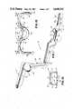
- FIG. 1is a perspective view of a preferred form of one-piece molding prior to assembly into a stapler according to the invention
- FIG. 2is a top plan view of the one-piece molding shown in FIG. 1;
- FIG. 3is a longitudinal vertical section of the unassembled molded piece, taken on line 3--3 of FIG. 2;
- FIG. 4is a plan view of the underside of the molded piece, prior to assembly
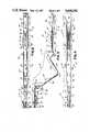
- FIG. 5is a vertical section of the assembled stapler in the "as-shipped" configuration, before the trigger has been pulled to advance the ratchet;
- FIG. 6is a fragmentary enlarged horizontal section taken on line 6--6 of FIG. 5, partly diagrammatic in nature, showing the relative positions of the pawl with respect to the stop and the ratchet at various stages of the operating cycle;
- FIG. 7is a longitudinal vertical section of the stapler after the trigger has been pulled far enough to advance the ratchet to its initial or "cocked" position;
- FIG. 8is an enlarged transverse vertical section taken on line 8--8 of FIG. 7;
- FIG. 9is an enlarged horizontal section taken on line 9--9 of FIG. 7, with the driver omitted for clarity;
- FIG. 10is a vertical section taken on line 10--10 of FIG. 9:
- FIG. 11is a longitudinal vertical section showing the stapler with the trigger fully retracted, the staple having been fully formed
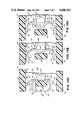
- FIG. 12is a fragmentary vertical section of the staple supply and anvil portion of the body, showing the staple ejection spring kicking a staple off the anvil;
- FIG. 13is an enlarged, fragmentary horizontal section, somewhat diagrammatic, of the front end portion of the stapler, taken on line 13--13 of FIG. 11, and shows the manner in which stapler is positioned with respect to approximated skin flaps to be stapled together;
- FIGS. 14A, B and Care a progressive series of enlarged horizontal sectional views of the front end of the stapler, showing a staple, driver, and anvil, as the staple is being formed, FIG. 14A showing the staple in open configuration when it is first engaged by the driver, FIG. 14B showing the staple after it has been partially formed on the anvil, and FIG. 14C showing the staple in fully formed or closed configuration;
- FIG. 15is an enlarged plan view of a preferred form of staple in accordance with the invention, in the open condition.
- FIG. 16is a plan view of the staple in closed condition.
- the stapler of this inventioncan be, and preferably is, formed as a unitary molding which incorporates, in one piece, a body, a pistol grip, a pivotable trigger, a staple driver or former, driver advance and return means, a staple holder or magazine, a staple feed spring, a backup feed spring, a driver advance ratchet, and a staple ejection spring.
- the drawingsshow the stapler as formed by a single piece molding, however, it should be understood that it can alternatively be assembled from two or more separately formed pieces.
- the staplercan be molded of a thermoplastic polyetherimide resin such as "Ultem 1000" or, as another example, from a polycarbonate resin such as "Lexan 124", both sold by General Electric Company. The molding process can be carried out by injection molding or other equivalent means.
- FIGS. 1-4A preferred form of unitary molding for this purpose is designated by 10, and is shown in FIGS. 1-4 in its unassembled state.
- the moldingbasically comprises three sections: a body section 11, a handle section 12, and a trigger section 13.
- the handle sectionlies between and connects the body and trigger sections.
- body section 11preferably includes components forming a staple guide passage 15 (see FIGS. 10 and 12), a magazine or holder 16 from which staples are fed into the staple guide passage, a feed spring 17, an anvil 18, a staple ejection spring 19, a driver guide channel 20, the pawl 21 of a driver ratchet, and two laterally spaced trigger pivot openings 22.
- the middle or handle section 12includes the forward part 26 of a pistol grip, an intermediate flexible or bendable portion 27 which forms the butt of the grip, the rear part 28 of the grip, and latch means 29, 29a for securing the front and rear grip components together.
- the trigger section 13 of molding 10includes components forming a trigger 33, two stub pivot axles 34, a driver 35, a driver retract spring 36, the rack 37 of the driver ratchet, a backup or supplementary feed spring 38, and connecting means 40 between the trigger and the driver for pulling driver 35 forward when trigger 33 is pulled.
- trigger section 13is swung up and forward from the handle section so that it is above or overlying the body.
- Driver 35is inserted into the driver guide channel 20 in the body so that it can slide forward therein.
- the triggeris pulled forward and over the front end of body section 11, which is passed partway through a body aperture 43 in the trigger section (FIG. 2).
- the trigger sectionis oriented so that trigger 33 extends at an angle, preferably substantially perpendicularly, to the body.
- the trigger sidescan be flexed out so that pivot axles 34, 34 can be snapped into pivot openings 22, 22 in the body.
- the rear part 28 of the gripis latched to the front part 26 by hooking grip latch portion 29 into the cooperating opening 29a (see FIG. 5).
- the handle section 12thereby forms a pistol grip type handle, rearwardly of the body and trigger, so that the trigger can be drawn to the grip to actuate the closure of a staple at the front end of the body sectin.
- This type of gripis more effective, from ergonometric considerations, than toggle-action means of the prior art which are operated between the fingertips.
- FIGS. 5 and followingshow the stapler in its assembled or use configuration.
- the trigger 33is pivoted for counterclockwise movement toward grip 48 in the direction indicated by arrow 49, (FIG. 5).
- the triggeris connected rearwardly to driver 35, at a point behind the trigger, by connecting means comprising straps 40, 40 on each side of the driver (best seen in FIG. 2).
- Driver 35slides in body 11 between upper and lower driver guide ways 50, 51 in body 11.
- the forward or tip end 53 of the driverengages and pushes forward the uppermost staple 54 of a stack 55 of staples.
- Stack 55is loaded into magazine 16 at the time the stapler is being assembled; or a separate magazine can be used.
- a visual counter or indicatorcan optionally be provided to show the number of staples remaining.
- the stack 55 of staplesis urged upwardly in body 11 by feed spring 17, against an overhead bridge or staple retainer 56, in position to be engaged by the driver.
- Spring 17is assisted by backup spring 38 which increases the upward force on the stack 55 of staples during closure of the staple.
- the top staple 54when engaged by the driver, is moved forwadly from stack 55 and along staple guide passage 15 until it abuts the downwardly projecting anvil 18.
- a preferred form of staple 54is shown enlarged in FIGS. 14A and 15 in its open or as-supplied configuration.
- the shape of the staple, prior to forming,is referred to herein as an "M" or “spider” shape.
- the staplehas a pair of parallel, straight outer legs 59, 59 having pointed or chisel tips 60, 60.
- the legs 59, 59are joined to straight intermediate sections 61, 61 by outer bends or knees 62, 62.
- the intermediate sections 61, 61extend upwardly and outwardly from a rounded, preferably semicircular, center section 64 at inner bends 65, 65 to form an obtuse center angle 66 between them.
- the obtuse angle 66 between intermediate sections 61, 61should preferably be about 140°-150°, most preferably 150°.
- the center section 64is an arc, preferably of about 180°-188°, most preferably 184°, and is preferably extended by short straight sections 72,72, at its upper ends, just inwardly of inner bends 65, 65 so that the center section is preferably somewhat U-shaped.
- the intermediate section 61, 61should form angles 67, 67 of about 100°-110°, most preferably 105°, with the axes 63 of the extensions 72,72 of the center section (see FIG. 15).
- the outer bendspreferably form acute angles 70, 70 of about 70°-75°, most preferably 75°, between the intermediate sections 61, 61 and the legs, so that the outer legs are parallel to each other.
- angles 67 and 70 of the inner and outer bendscollectively they should be such that when the center section 64 is straightened in closure, the legs will be slightlty inbent (about 2°-5°), as shown in FIG. 16.
- the sum of the angles of an inner bend 65 and an outer bend 62should be less than 180°, preferably about 178°.
- the staplesmay be made of about 0.02" diameter round stainless steel wire; they are usually quite small, and may, for example, be about 0.2" high by 0.4" wide in open form.
- Outer legs 59, 59which are straight rather than curved as in the prior art, are provided to impart a better skin gathering ability, and to hold the edges of the wound more tightly together after closure.
- the stapleis closed by flattening or straightening the rounded center portion 64; there should be essentially no bending at either the outer bends 62 or the inner bends 65.
- the stapleIn the closed configuration the staple has a pentagonal "B" shape, shown in FIGS. 13, 14C and 16, defined by the now straightened center section 64, the two straight sections 61, 61, and the two straight legs 59, 59, which are inbent toward the section 64.
- the tips 60are brought together and may actually overlap to a small degree, in order to provide for some possible springback after forming.
- the angle 71 between legs 59, 59 in closed configurationshould be about 175°-178° (see FIG. 16).
- the stapled skin flapswill slide out and apart on the staple legs 59, 59 to the outer bends 62, 62 thereof, so that the two edges of the cut abut for healing.
- the inbent shape of the staplewith the skin flaps seated on the intermediate sections and the outer bends and the legs inbent toward the center part of the staple, resists rotation about an axis perpendicular to the plane of the staple.
- the pointed tipsremain directly beneath center section 64, which is outside the skin; this facilitates staple removal.
- Stapler body section 11has two spaced side flanges 73, 74, which are connected to one another at various longitudinal positions by transverse webs or bridges (FIGS. 9 and 10).
- trigger 33straddles these body flanges on the outside, and projects approximately perpendicularly to the body.
- the triggeris pivotally connected to and between opposed openings 22 in ears 75 depending from body flanges 73 and 74.
- the anvil or staple forming post 18depends from web 76 (FIG. 9) into the path of staple movement in staple guide passage 15, defined by and between parallel upper and lower ways 50, 51 (FIG. 10). These ways are formed on the inside surfaces of body flanges 73, 74.
- Staple ejection spring 19is presented immediately rearwardly of anvil 18 and is a leaf spring having a tip 78 which exerts a downward bias or spring force on a staple at the anvil, urging the staple downwardly to eject it from anvil 18 (see FIGS. 10, 12, and 14C) when the staple is no longer pressed against the anvil by the driver.
- Staplesare supplied upwardly from below into staple guide passage 15, from the magazine or supply means 55 (see FIGS. 5 and 10).
- This magazine 55has two spaced vertical ribs 79, 79, set in from the respective body flanges, and a center channel or guide 80 between them (FIG. 9).
- Guide 80receives and guides the rounded center section 64 of the staples, while the ribs 79, 79 project between the staple legs 59, 59.
- the staplermay be made as a "low-count" unit, i.e., the supply may be sized to contain only a small number of staples. However, will be apparent that the supply means can be changed to accommodate a greater number of staples.
- the stack of staples 55is held upwardly by a forwardly projecting cantilever leaf spring 17 which is supported at its rearward end by the two body sides 73, 74.
- the backup spring 38projects forwardly from driver 35 (see FIGS. 2 and 3), and in use applies an upward biasing force to feed spring 17, and hence to the staples.
- the supplementary spring 38is proximate to but does not engage or exert force on feed spring 17.
- trigger 33is pulled, forward motion of the driver brings the tip 82 of the spring into camming and biasing contact with spring 17, as shown in FIG. 7.
- spring 38applies an increasing force to spring 17, thereby insuring the staples are held upwardly and in contact with the driver.
- the tip 82 of spring 38engages spring 17 between a bent knee 83 or crook thereof and the point of attachment 84 to the body, and exerts an upward force on feed spring 17.
- Pulling trigger 33 to its fully retracted position shown in FIG. 11causes the tip 82 of supplementary spring 38 to slide past knee 83, thereby shortening the effective length of the lever acting on spring 17 and increasing the biasing force on stack 55 as the trigger is progressively pulled back.
- the purpose of the staple feed spring 17is to apply an upward pressure force on the staples at all times, after the magazine is loaded; the purpose of the backup or supplementary spring 38 is to apply increased force when the driver is "cocked" just prior to first use. This force increases as the driver engages the staple 54, and insures that the staple does not "cock” or get cammed downwardly out of the path of the driver end 53.
- the springis not stressed until the gun is cocked immediately prior to first use, which prevents loss of force from plastic creep.
- the driver 35is formed as part of trigger section 13, wherein it projects between the sides of the trigger.
- the driveris an elongated tongue which is guided and confined in a driver guide channel 20, defined by the guide ways 50, 51 of the body.
- Driver guide channel 20is a rearward extension of the staple guide passage 15.
- the driverhas a tip 53 which is specially configured, as best shown in FIG. 14B, to exert a staple bending force which progressively increases as the staple tips 60, 60 are brought together. This is done by reducing the lever arm, and thereby increasing the force applied to the staple by the driver, as the staple is closed.
- the anvil 18acts as the fulcrum about which the rounded center 64 of the staple is straightened; force is applied to the staple on each side of the anvil by the driver at points which move inward stepwise, toward the centerline, as the staple is closed.
- driver tip 53is doubly stepped or recessed, to present longitudinally offset staple centering and forming pockets which engage different parts of the staple as it is progressively formed in clinching.
- the driverhas a pair of first or outer recesses or pockets, shown in FIG. 14A at 86, which engage the outer bends 62, 62 of staple 54. Rearwardly and inwardly of the outer recess sections 86, 86 are inner recesses 87, 87, which engage the staple inner bends 65, 65 (FIG. 14B).
- a central recess 88is provided between and rearwardly of the inner recesses 87, 87.
- the stapleWhen the driver advances staple 54 to the anvil, the staple is first engaged at its outer bends 62, 62, by the outer recesses 86, 86. These apply force to bend the staple, moving the staple outer bends forward while the staple center 64 is straightened on the anvil. As this occurs, the inner bends 65, 65 come into engagement with driver inner recesses or pockets 87, 87; the lever arm, i.e., the lateral distance between these pockets and anvil 18, is less than that between the anvil and the outer pockets, so that the bending force increases.
- the tipsare brought together smoothly without excessive hand force being required (FIGS. 1B and C).
- the driver tipengages and lifts staple ejection spring 19 when the staple is being closed; thereafter, when the driver is moved away from the formed staple, spring 19 is released and kicks the staple off anvil 18, as shown in FIG. 12.
- a ratchet mechanismwhich permits reverse driver movement only after the driver has been advanced to its forwardmost position, corresponding to the ejection of the staple from the anvil.
- the ratchet mechanismis best seen in FIGS.
- the ratchet mechanismalso includes a stop 91 which is spaced from the rack on the underside of driver 35.
- the unitis supplied or shipped with the ratchet in an un-stressed condition wherein the pawl is not engaged with either stop 91 or rack 37 (FIG. 5).
- the driverAs trigger 33 is pulled, the driver is advanced into the body, carrying rack 37 in the direction of arrow 92 in FIG. 6. This brings stop 91 into camming engagement with pawl 21.
- the pawl spring 90is flexed, allowing pawl 21 to move to the right in FIG.
- the ratchet rack 37moves progressively forward past pawl 21, and the pawl seats nearer and nearer the rear of the rack.
- the pawl spring leg 90is increasingly deflected, and when the pawl moves beyond the last seat on the rack ("End” in FIGS. 6), the stress of spring 90 snaps the pawl laterally across the end of the rack to the other or flat side 93 of the rack ("Return” position shown in FIG. 6). This permits the rack to be moved rearwardly (to the right in FIG. 6) past the pawl, to disengage and reset in the ready position for the next staple.
- the stopprevents the driver from returning to the as-shipped position (see FIG. 7).
- Trigger 33has two spaced sides 94, 95, connected by an end web 96 and defining body aperture 43 between them. These two sides flank but are spaced from driver 35 and backup spring 38.
- Two tension members, straps or yokes 40,40connect what in assembled state is the top part 97 of the trigger (above the axle 34 and adjacent retract spring 36) to the driver (FIGS. 1 and 2). In assembled condition, the body extends through aperture 43 between trigger sides 94, 95, so that the trigger straddles the body.
- the top 97 of the triggeris arcuate or radiused about pivot axles 34, 34 to provide swingable support for the straps.
- the triggerstraddles and is pivotally connected to apertures in ears, one of which is shown at 75 in FIG. 5, which project below the body sides 73, 74.
- the pair of stub axles 34, 34have arrowhead snaps 98, by which they are locked into the pivot openings 22, 22 once the trigger is positioned with respect to the body.
- the driver return spring 36has an S-shape (FIG. 5), and extends forward from rear grip surface 28 to the driver (FIG. 5). This spring has a thin bending portion 99, and is tensioned when the trigger is pulled forward over the body. When the driver is pulled forward by the straps 40, 40, spring 36 exerts a force in the direction of arrow 100 to retract the driver and thereby return the trigger to its normal position.
Landscapes
- Health & Medical Sciences (AREA)
- Surgery (AREA)
- Life Sciences & Earth Sciences (AREA)
- Engineering & Computer Science (AREA)
- General Health & Medical Sciences (AREA)
- Biomedical Technology (AREA)
- Heart & Thoracic Surgery (AREA)
- Medical Informatics (AREA)
- Molecular Biology (AREA)
- Animal Behavior & Ethology (AREA)
- Nuclear Medicine, Radiotherapy & Molecular Imaging (AREA)
- Public Health (AREA)
- Veterinary Medicine (AREA)
- Mechanical Engineering (AREA)
- Portable Nailing Machines And Staplers (AREA)
- Diaphragms For Electromechanical Transducers (AREA)
- Materials For Medical Uses (AREA)
- Surgical Instruments (AREA)
- Electric Clocks (AREA)
- Dovetailed Work, And Nailing Machines And Stapling Machines For Wood (AREA)
- Sheet Holders (AREA)
Abstract
Description
Claims (54)
Priority Applications (13)
| Application Number | Priority Date | Filing Date | Title |
|---|---|---|---|
| US06/793,955US4648542A (en) | 1985-11-01 | 1985-11-01 | Disposable stapler |
| ZA867583AZA867583B (en) | 1985-11-01 | 1986-10-03 | Disposable stapler |
| DE8686307991TDE3680501D1 (en) | 1985-11-01 | 1986-10-15 | CLAMP FOR ONE-TIME USE. |
| AT86307991TATE65374T1 (en) | 1985-11-01 | 1986-10-15 | SINGLE USE STAPLER. |
| EP86307991AEP0229453B1 (en) | 1985-11-01 | 1986-10-15 | Disposable stapler |
| CA000520619ACA1276401C (en) | 1985-11-01 | 1986-10-16 | Disposable stapler |
| MX4167AMX164517B (en) | 1985-11-01 | 1986-10-27 | DISPOSABLE STAPLER |
| CN86106345ACN1008968B (en) | 1985-11-01 | 1986-10-31 | Disposable stapler |
| AU64574/86AAU581349B2 (en) | 1985-11-01 | 1986-10-31 | Disposable stapler |
| BR8605399ABR8605399A (en) | 1985-11-01 | 1986-10-31 | ELONGED TEMPLATE FOR ASSEMBLY IN STAPLER, STAPLER AND CLAMP AND STAPLER TO FORM THE CLAMP |
| JP61260553AJPS62112543A (en) | 1985-11-01 | 1986-10-31 | Staple, stapler and molded body assembled into stapler |
| KR1019860009218AKR900002917B1 (en) | 1985-11-01 | 1986-11-01 | Disposable stapler |
| AU27040/88AAU596036B2 (en) | 1985-11-01 | 1988-12-19 | Disposable stapler |
Applications Claiming Priority (1)
| Application Number | Priority Date | Filing Date | Title |
|---|---|---|---|
| US06/793,955US4648542A (en) | 1985-11-01 | 1985-11-01 | Disposable stapler |
Publications (1)
| Publication Number | Publication Date |
|---|---|
| US4648542Atrue US4648542A (en) | 1987-03-10 |
Family
ID=25161250
Family Applications (1)
| Application Number | Title | Priority Date | Filing Date |
|---|---|---|---|
| US06/793,955Expired - LifetimeUS4648542A (en) | 1985-11-01 | 1985-11-01 | Disposable stapler |
Country Status (12)
| Country | Link |
|---|---|
| US (1) | US4648542A (en) |
| EP (1) | EP0229453B1 (en) |
| JP (1) | JPS62112543A (en) |
| KR (1) | KR900002917B1 (en) |
| CN (1) | CN1008968B (en) |
| AT (1) | ATE65374T1 (en) |
| AU (2) | AU581349B2 (en) |
| BR (1) | BR8605399A (en) |
| CA (1) | CA1276401C (en) |
| DE (1) | DE3680501D1 (en) |
| MX (1) | MX164517B (en) |
| ZA (1) | ZA867583B (en) |
Cited By (39)
| Publication number | Priority date | Publication date | Assignee | Title |
|---|---|---|---|---|
| US4784137A (en)* | 1987-11-16 | 1988-11-15 | Kulik Yaroslav P | Surgical suturing instrument |
| USD307797S (en) | 1987-09-24 | 1990-05-08 | Ethicon, Inc. | Skin stapler |
| USD326323S (en) | 1989-09-28 | 1992-05-19 | Ethicon, Inc. | Cartridge for a skin stapler |
| USD327323S (en) | 1989-08-02 | 1992-06-23 | Ethicon,Inc. | Combination skin stapler and rotating head |
| US5161725A (en)* | 1990-02-13 | 1992-11-10 | Ethicon, Inc. | Rotating head skin stapler |
| US5240164A (en)* | 1990-02-13 | 1993-08-31 | Ethicon, Inc. | Rotating head skin stapler |
| EP0826340A3 (en)* | 1996-09-03 | 1998-11-04 | Medinov-Amp | Support for surgical staple of elastic, superelastic or shape memory type |
| US5908149A (en)* | 1997-03-12 | 1999-06-01 | Ethicon Endo-Surgery, Inc. | Skin stapler with multi-directional release mechanism |
| US5938101A (en)* | 1997-05-14 | 1999-08-17 | Ethicon Endo-Surgery, Inc. | Skin stapler with movable anvil |
| US5937951A (en)* | 1997-07-18 | 1999-08-17 | Ethicon Endo-Surgery, Inc. | Skin stapler with rack and pinion staple feed mechanism |
| US20040267311A1 (en)* | 2001-10-05 | 2004-12-30 | Viola Frank J. | Surgical stapling apparatus and method |
| US20050222616A1 (en)* | 2001-10-05 | 2005-10-06 | Rethy Csaba L | Surgical fastener applying apparatus |
| US20070125827A1 (en)* | 2002-05-10 | 2007-06-07 | Tyco Healthcare Group Lp | Surgical stapling apparatus having a wound closure material applicator assembly |
| US7296722B2 (en) | 2003-10-17 | 2007-11-20 | Tyco Healthcare Group Lp | Surgical fastener applying apparatus with controlled beam deflection |
| US20090101693A1 (en)* | 2007-10-19 | 2009-04-23 | Tyco Healthcare Group Lp | Two Piece Anvil For Surgical Stapler |
| US20100187285A1 (en)* | 2009-01-26 | 2010-07-29 | Harris Jason L | Surgical stapler for applying a large staple though a small delivery port and a method of using the stapler to secure a tissue fold |
| US20100191262A1 (en)* | 2009-01-26 | 2010-07-29 | Harris Jason L | Surgical stapler for applying a large staple through small delivery port and a method of using the stapler to secure a tissue fold |
| US20100191258A1 (en)* | 2009-01-26 | 2010-07-29 | Harris Jason L | surgical stapler for applying a large staple through a small delivery port and a method of using the stapler to secure a tissue fold |
| US20100191282A1 (en)* | 2009-01-26 | 2010-07-29 | Harris Jason L | Surgical Stapler For Applying A Large Staple Through A Small Delivery Port And A Method of Using The Stapler To Secure A Tissue Fold |
| US20100187284A1 (en)* | 2009-01-26 | 2010-07-29 | Lawrence Crainich | Apparatus For Feeding Staples In a Low Profile Surgical Stapler |
| US20100187283A1 (en)* | 2009-01-26 | 2010-07-29 | Lawrence Crainich | Method For Feeding Staples In a Low Profile Surgical Stapler |
| US20100280367A1 (en)* | 2009-04-30 | 2010-11-04 | Ducharme Richard W | System and method for fiducial deployment |
| WO2012103286A1 (en)* | 2011-01-28 | 2012-08-02 | Ethicon Endo-Surgery, Inc. | A surgical stapler fastening device |
| EP2537471A1 (en)* | 2011-06-21 | 2012-12-26 | Ethicon Endo-Surgery, Inc. | A surgical fastener having a safety feature |
| US8453905B2 (en) | 2009-01-26 | 2013-06-04 | Ethicon Endo-Surgery, Inc. | Surgical fastener for applying a large staple through a small delivery port |
| US8469252B2 (en) | 2009-01-26 | 2013-06-25 | Ethicon Endo-Surgery, Inc. | Surgical stapler fastening device with adjustable anvil |
| US9265501B2 (en) | 2012-09-06 | 2016-02-23 | Sabic Global Technologies B.V. | Surgical stapler with corrugated thermoplastic leaf spring |
| US9468440B2 (en) | 2011-03-31 | 2016-10-18 | Aesculap Ag | Surgical clip applicator |
| US9522264B2 (en) | 2013-02-26 | 2016-12-20 | Cook Medical Technologies Llc | Ratchet-slide handle and system for fiducial deployment |
| US9713471B2 (en) | 2009-01-26 | 2017-07-25 | Ethicon Endo-Surgery, Inc. | Surgical device with tandem fasteners |
| US9770262B2 (en) | 2014-06-09 | 2017-09-26 | Cook Medical Technologies Llc | Screw-driven handles and systems for fiducial deployment |
| US9980716B2 (en) | 2012-03-21 | 2018-05-29 | Ethicon Llc | Methods and devices for creating tissue plications |
| US10123848B2 (en) | 2014-12-03 | 2018-11-13 | Cook Medical Technologies Llc | EUS fiducial needle stylet handle assembly |
| US10258373B2 (en) | 2011-06-28 | 2019-04-16 | Cook Medical Technologies Llc | Fiducial deployment needle system |
| US10278695B2 (en) | 2013-11-04 | 2019-05-07 | Quickring Medical Technologies Ltd. | Surgical stapler |
| CN109875627A (en)* | 2019-02-26 | 2019-06-14 | 宁波市爱达维电器有限公司 | Medical long kiss type stitching unstrument |
| CN109875628A (en)* | 2019-02-26 | 2019-06-14 | 宁波市爱达维电器有限公司 | The staple cartridge structure of medical suturing instrument |
| US10363407B2 (en) | 2014-06-16 | 2019-07-30 | Cook Medical Technologies Llc | Plunger-driven collet handle and system for fiducial deployment |
| US10675108B2 (en)* | 2018-02-06 | 2020-06-09 | Ethicon Llc | Surgical clip applier with clip forming system |
Families Citing this family (8)
| Publication number | Priority date | Publication date | Assignee | Title |
|---|---|---|---|---|
| US4648542A (en)* | 1985-11-01 | 1987-03-10 | Senmed, Inc. | Disposable stapler |
| CA1286185C (en)* | 1986-07-14 | 1991-07-16 | Harold E. Froehlich | Bent back box staple and staple closing mechanism with split actuator |
| US4874122A (en)* | 1986-07-14 | 1989-10-17 | Minnesota Mining And Manufacturing Company | Bent back box staple and staple closing mechanism with split actuator |
| US4951860A (en)* | 1987-12-28 | 1990-08-28 | Edward Weck & Co. | Method and apparatus for storing, dispensing and applying surgical staples |
| GB8919691D0 (en)* | 1989-08-31 | 1989-10-11 | Taylor James | Improvements in surgical stapling devices |
| AU7082091A (en)* | 1990-02-13 | 1991-08-15 | Ethicon Inc. | Rotating head skin stapler |
| US6149660A (en)* | 1996-04-22 | 2000-11-21 | Vnus Medical Technologies, Inc. | Method and apparatus for delivery of an appliance in a vessel |
| CN104921792A (en)* | 2015-06-12 | 2015-09-23 | 季欣然 | Bone pinning device for fracture fixation |
Citations (20)
| Publication number | Priority date | Publication date | Assignee | Title |
|---|---|---|---|---|
| US1910688A (en)* | 1931-08-03 | 1933-05-23 | Bella Goodstein | Staple |
| US1945377A (en)* | 1933-10-25 | 1934-01-30 | Charles B Goodstein | Stapling machine |
| DE618955C (en)* | 1932-11-12 | 1935-09-19 | Feodor Hoernlimann Dipl Ing | Equipment for the production of Ortpfählen with foldable jacket |
| US3275211A (en)* | 1965-05-10 | 1966-09-27 | United States Surgical Corp | Surgical stapler with replaceable cartridge |
| US3583622A (en)* | 1969-03-21 | 1971-06-08 | Robert Frank Graeff | Stapler |
| US3827277A (en)* | 1969-07-29 | 1974-08-06 | Ici Ltd | Applicator for surgical clips |
| US3873016A (en)* | 1973-11-30 | 1975-03-25 | Meyer Fishbein | Pliers type surgical stapler for joining disunited skin or fascia |
| US3906957A (en)* | 1973-04-24 | 1975-09-23 | Ici Ltd | Forceps |
| US4014492A (en)* | 1975-06-11 | 1977-03-29 | Senco Products, Inc. | Surgical staple |
| US4127227A (en)* | 1976-10-08 | 1978-11-28 | United States Surgical Corporation | Wide fascia staple cartridge |
| US4185762A (en)* | 1978-03-27 | 1980-01-29 | Minnesota Mining And Manufacturing Company | Medical stapling device |
| US4202480A (en)* | 1979-02-26 | 1980-05-13 | Minnesota Mining And Manufacturing Company | Stapler including means for preventing double feeding of staples |
| US4256251A (en)* | 1978-04-24 | 1981-03-17 | Lawrence M. Smith | Surgical staplers and staple |
| US4321002A (en)* | 1978-03-27 | 1982-03-23 | Minnesota Mining And Manufacturing Company | Medical stapling device |
| US4399810A (en)* | 1979-11-28 | 1983-08-23 | Samuels Peter B | Skin clip and applier |
| WO1984001706A1 (en)* | 1982-11-04 | 1984-05-10 | Minnesota Mining & Mfg | Stapler with retractable anvil |
| US4477007A (en)* | 1979-02-26 | 1984-10-16 | Minnesota Mining And Manufacturing Company | Stapler with intermediate latching mechanism |
| US4477008A (en)* | 1981-09-03 | 1984-10-16 | Minnesota Mining And Manufacturing Company | Stapler |
| US4505273A (en)* | 1982-02-10 | 1985-03-19 | Intermedicat Gmbh | Surgical staple |
| US4523707A (en)* | 1982-05-04 | 1985-06-18 | Blake Joseph W Iii | Surgical stapler |
Family Cites Families (4)
| Publication number | Priority date | Publication date | Assignee | Title |
|---|---|---|---|---|
| IE36591B1 (en)* | 1971-09-17 | 1976-12-08 | Ici Ltd | Wound clip applicator |
| US4645111A (en)* | 1981-07-08 | 1987-02-24 | Howmedica, Inc. | Surgical stapler with retractable anvil |
| CA1182709A (en)* | 1981-09-03 | 1985-02-19 | Kent R. Struble | Stapler |
| US4648542A (en)* | 1985-11-01 | 1987-03-10 | Senmed, Inc. | Disposable stapler |
- 1985
- 1985-11-01USUS06/793,955patent/US4648542A/ennot_activeExpired - Lifetime
- 1986
- 1986-10-03ZAZA867583Apatent/ZA867583B/enunknown
- 1986-10-15ATAT86307991Tpatent/ATE65374T1/ennot_activeIP Right Cessation
- 1986-10-15DEDE8686307991Tpatent/DE3680501D1/ennot_activeExpired - Lifetime
- 1986-10-15EPEP86307991Apatent/EP0229453B1/ennot_activeExpired - Lifetime
- 1986-10-16CACA000520619Apatent/CA1276401C/ennot_activeExpired - Lifetime
- 1986-10-27MXMX4167Apatent/MX164517B/enunknown
- 1986-10-31CNCN86106345Apatent/CN1008968B/ennot_activeExpired
- 1986-10-31AUAU64574/86Apatent/AU581349B2/ennot_activeCeased
- 1986-10-31BRBR8605399Apatent/BR8605399A/ennot_activeIP Right Cessation
- 1986-10-31JPJP61260553Apatent/JPS62112543A/enactivePending
- 1986-11-01KRKR1019860009218Apatent/KR900002917B1/ennot_activeExpired
- 1988
- 1988-12-19AUAU27040/88Apatent/AU596036B2/ennot_activeCeased
Patent Citations (20)
| Publication number | Priority date | Publication date | Assignee | Title |
|---|---|---|---|---|
| US1910688A (en)* | 1931-08-03 | 1933-05-23 | Bella Goodstein | Staple |
| DE618955C (en)* | 1932-11-12 | 1935-09-19 | Feodor Hoernlimann Dipl Ing | Equipment for the production of Ortpfählen with foldable jacket |
| US1945377A (en)* | 1933-10-25 | 1934-01-30 | Charles B Goodstein | Stapling machine |
| US3275211A (en)* | 1965-05-10 | 1966-09-27 | United States Surgical Corp | Surgical stapler with replaceable cartridge |
| US3583622A (en)* | 1969-03-21 | 1971-06-08 | Robert Frank Graeff | Stapler |
| US3827277A (en)* | 1969-07-29 | 1974-08-06 | Ici Ltd | Applicator for surgical clips |
| US3906957A (en)* | 1973-04-24 | 1975-09-23 | Ici Ltd | Forceps |
| US3873016A (en)* | 1973-11-30 | 1975-03-25 | Meyer Fishbein | Pliers type surgical stapler for joining disunited skin or fascia |
| US4014492A (en)* | 1975-06-11 | 1977-03-29 | Senco Products, Inc. | Surgical staple |
| US4127227A (en)* | 1976-10-08 | 1978-11-28 | United States Surgical Corporation | Wide fascia staple cartridge |
| US4185762A (en)* | 1978-03-27 | 1980-01-29 | Minnesota Mining And Manufacturing Company | Medical stapling device |
| US4321002A (en)* | 1978-03-27 | 1982-03-23 | Minnesota Mining And Manufacturing Company | Medical stapling device |
| US4256251A (en)* | 1978-04-24 | 1981-03-17 | Lawrence M. Smith | Surgical staplers and staple |
| US4202480A (en)* | 1979-02-26 | 1980-05-13 | Minnesota Mining And Manufacturing Company | Stapler including means for preventing double feeding of staples |
| US4477007A (en)* | 1979-02-26 | 1984-10-16 | Minnesota Mining And Manufacturing Company | Stapler with intermediate latching mechanism |
| US4399810A (en)* | 1979-11-28 | 1983-08-23 | Samuels Peter B | Skin clip and applier |
| US4477008A (en)* | 1981-09-03 | 1984-10-16 | Minnesota Mining And Manufacturing Company | Stapler |
| US4505273A (en)* | 1982-02-10 | 1985-03-19 | Intermedicat Gmbh | Surgical staple |
| US4523707A (en)* | 1982-05-04 | 1985-06-18 | Blake Joseph W Iii | Surgical stapler |
| WO1984001706A1 (en)* | 1982-11-04 | 1984-05-10 | Minnesota Mining & Mfg | Stapler with retractable anvil |
Cited By (91)
| Publication number | Priority date | Publication date | Assignee | Title |
|---|---|---|---|---|
| USD307797S (en) | 1987-09-24 | 1990-05-08 | Ethicon, Inc. | Skin stapler |
| US4784137A (en)* | 1987-11-16 | 1988-11-15 | Kulik Yaroslav P | Surgical suturing instrument |
| USD327323S (en) | 1989-08-02 | 1992-06-23 | Ethicon,Inc. | Combination skin stapler and rotating head |
| USD326323S (en) | 1989-09-28 | 1992-05-19 | Ethicon, Inc. | Cartridge for a skin stapler |
| US5161725A (en)* | 1990-02-13 | 1992-11-10 | Ethicon, Inc. | Rotating head skin stapler |
| US5240164A (en)* | 1990-02-13 | 1993-08-31 | Ethicon, Inc. | Rotating head skin stapler |
| EP0826340A3 (en)* | 1996-09-03 | 1998-11-04 | Medinov-Amp | Support for surgical staple of elastic, superelastic or shape memory type |
| US5908149A (en)* | 1997-03-12 | 1999-06-01 | Ethicon Endo-Surgery, Inc. | Skin stapler with multi-directional release mechanism |
| US5938101A (en)* | 1997-05-14 | 1999-08-17 | Ethicon Endo-Surgery, Inc. | Skin stapler with movable anvil |
| US5937951A (en)* | 1997-07-18 | 1999-08-17 | Ethicon Endo-Surgery, Inc. | Skin stapler with rack and pinion staple feed mechanism |
| US8091754B2 (en) | 2000-10-13 | 2012-01-10 | Tyco Healthcare Group Lp | Surgical fastener applying apparatus |
| US10231733B2 (en) | 2000-10-13 | 2019-03-19 | Covidien Lp | Surgical fastener applying apparatus |
| US20100282817A1 (en)* | 2000-10-13 | 2010-11-11 | Tyco Healthcare Group Lp | Surgical fastener applying apparatus |
| US8074861B2 (en) | 2000-10-13 | 2011-12-13 | Tyco Healthcare Group Lp | Surgical fastener applying apparatus |
| US20100193570A1 (en)* | 2000-10-13 | 2010-08-05 | Ehrenfels Karl H | Surgical fastener applying apparatus |
| US8505801B2 (en) | 2000-10-13 | 2013-08-13 | Covidien Lp | Surgical fastener applying apparatus |
| US9402629B2 (en) | 2000-10-13 | 2016-08-02 | Covidien Lp | Surgical fastener applying apparatus |
| US10959729B2 (en) | 2000-10-13 | 2021-03-30 | Covidien Lp | Surgical fastener applying apparatus |
| US20070125828A1 (en)* | 2001-10-05 | 2007-06-07 | Tyco Healthcare Group Lp | Surgical fastener applying apparatus |
| US20080116244A1 (en)* | 2001-10-05 | 2008-05-22 | Tyco Healthcare Group Lp | Surgical fastener applying apparatus |
| US20050222616A1 (en)* | 2001-10-05 | 2005-10-06 | Rethy Csaba L | Surgical fastener applying apparatus |
| US7188758B2 (en) | 2001-10-05 | 2007-03-13 | Tyco Healthcare Group Lp | Surgical stapling apparatus and method |
| US7326232B2 (en) | 2001-10-05 | 2008-02-05 | Tyco Healthcare Group Lp | Surgical stapling apparatus and method |
| US7334717B2 (en) | 2001-10-05 | 2008-02-26 | Tyco Healthcare Group Lp | Surgical fastener applying apparatus |
| US20060138194A1 (en)* | 2001-10-05 | 2006-06-29 | Tyco Healthcare Group Lp | Surgical stapling apparatus and method |
| US20070145096A1 (en)* | 2001-10-05 | 2007-06-28 | Tyco Healthcare Group Lp | Surgical stapling apparatus and method |
| US20080302854A1 (en)* | 2001-10-05 | 2008-12-11 | Rethy Csaba L | Surgical Fastener Applying Apparatus |
| US20060138193A1 (en)* | 2001-10-05 | 2006-06-29 | Tyco Healthcare Group Lp | Surgical stapling apparatus and method |
| US7942300B2 (en) | 2001-10-05 | 2011-05-17 | Tyco Healthcare Group Lp | Surgical fastener applying apparatus |
| US7032799B2 (en) | 2001-10-05 | 2006-04-25 | Tyco Healthcare Group Lp | Surgical stapling apparatus and method |
| US20040267311A1 (en)* | 2001-10-05 | 2004-12-30 | Viola Frank J. | Surgical stapling apparatus and method |
| US7631794B2 (en) | 2001-10-05 | 2009-12-15 | Tyco Healthcare Group Lp | Surgical fastener applying apparatus |
| US7631793B2 (en) | 2001-10-05 | 2009-12-15 | Tyco Healthcare Group Lp | Surgical fastener applying apparatus |
| US20100230468A1 (en)* | 2002-05-10 | 2010-09-16 | Tyco Healthcare Group Lp | Surgical Stapling Apparatus Having a Wound Closure Material Applicator Assembly |
| US20070175954A1 (en)* | 2002-05-10 | 2007-08-02 | Tyco Healthcare Group Lp | Surgical stapling apparatus having a wound closure material applicator assembly |
| US7740160B2 (en) | 2002-05-10 | 2010-06-22 | Tyco Healthcare Group Lp | Surgical stapling apparatus having a wound closure material applicator assembly |
| US20070125827A1 (en)* | 2002-05-10 | 2007-06-07 | Tyco Healthcare Group Lp | Surgical stapling apparatus having a wound closure material applicator assembly |
| US7571845B2 (en) | 2002-05-10 | 2009-08-11 | Tyco Healthcare Group Lp | Surgical stapling apparatus having a wound closure material applicator assembly |
| US7238195B2 (en) | 2002-05-10 | 2007-07-03 | Tyco Healthcare Group Lp | Wound closure material applicator and stapler |
| US8286850B2 (en) | 2002-05-10 | 2012-10-16 | Tyco Healthcare Group Lp | Surgical stapling apparatus having a wound closure material applicator assembly |
| US7699205B2 (en) | 2003-10-17 | 2010-04-20 | Tyco Healthcare Group Lp | Surgical fastener applying apparatus with controlled beam deflection |
| US9241711B2 (en) | 2003-10-17 | 2016-01-26 | Covidien Lp | Surgical fastener applying apparatus with controlled beam deflection |
| US10154843B2 (en) | 2003-10-17 | 2018-12-18 | Covidien Lp | Surgical fastener applying apparatus with controlled beam deflection |
| US10835252B2 (en) | 2003-10-17 | 2020-11-17 | Covidien Lp | Surgical fastener applying apparatus with controlled beam deflection |
| US8701961B2 (en) | 2003-10-17 | 2014-04-22 | Covidien Lp | Surgical fastener applying apparatus with controlled beam deflection |
| US7543729B2 (en) | 2003-10-17 | 2009-06-09 | Tyco Healthcare Group Lp | Surgical fastener applying apparatus with controlled beam deflection |
| US20090127313A1 (en)* | 2003-10-17 | 2009-05-21 | David Ivanko | Surgical fastener applying apparatus with controlled beam deflection |
| US20100170933A1 (en)* | 2003-10-17 | 2010-07-08 | Tyco Healthcare Group Lp | Surgical Fastener Applying Apparatus with Controlled Beam Deflection |
| US7296722B2 (en) | 2003-10-17 | 2007-11-20 | Tyco Healthcare Group Lp | Surgical fastener applying apparatus with controlled beam deflection |
| US8011552B2 (en) | 2003-10-17 | 2011-09-06 | Tyco Healthcare Group Lp | Surgical fastener applying apparatus with controlled beam deflection |
| US8292149B2 (en) | 2003-10-17 | 2012-10-23 | Tyco Healthcare Group Lp | Surgical fastener applying apparatus with controlled beam deflection |
| US20080054046A1 (en)* | 2003-10-17 | 2008-03-06 | David Ivanko | Surgical fastener applying apparatus with controlled beam deflection |
| US7942304B2 (en)* | 2007-10-19 | 2011-05-17 | Tyco Healthcare Group Lp | Two piece anvil for surgical stapler |
| US20110192880A1 (en)* | 2007-10-19 | 2011-08-11 | Taylor Eric J | Two piece anvil for surgical stapler |
| US8205620B2 (en) | 2007-10-19 | 2012-06-26 | Tyco Healthcare Group Lp | Two piece anvil for surgical stapler |
| US20090101693A1 (en)* | 2007-10-19 | 2009-04-23 | Tyco Healthcare Group Lp | Two Piece Anvil For Surgical Stapler |
| US8602286B2 (en) | 2009-01-26 | 2013-12-10 | Ethicon Endo-Surgery, Inc. | Apparatus for feeding staples in a low profile surgical stapler |
| US8801732B2 (en) | 2009-01-26 | 2014-08-12 | Ethicon Endo-Surgery, Inc. | Surgical stapler to secure a tissue fold |
| US8453905B2 (en) | 2009-01-26 | 2013-06-04 | Ethicon Endo-Surgery, Inc. | Surgical fastener for applying a large staple through a small delivery port |
| US8469252B2 (en) | 2009-01-26 | 2013-06-25 | Ethicon Endo-Surgery, Inc. | Surgical stapler fastening device with adjustable anvil |
| US11540825B2 (en) | 2009-01-26 | 2023-01-03 | Ethicon Endo-Surgery, Inc. | Surgical device with tandem fasteners |
| US9713468B2 (en) | 2009-01-26 | 2017-07-25 | Ethicon Endo-Surgery, Inc. | Surgical stapler for applying a large staple through a small delivery port and a method of using the stapler to secure a tissue fold |
| US20100191262A1 (en)* | 2009-01-26 | 2010-07-29 | Harris Jason L | Surgical stapler for applying a large staple through small delivery port and a method of using the stapler to secure a tissue fold |
| US20100187285A1 (en)* | 2009-01-26 | 2010-07-29 | Harris Jason L | Surgical stapler for applying a large staple though a small delivery port and a method of using the stapler to secure a tissue fold |
| US10779819B2 (en) | 2009-01-26 | 2020-09-22 | Ethicon Endo-Surgery, Inc. | Surgical device with tandem fasteners |
| US20100187283A1 (en)* | 2009-01-26 | 2010-07-29 | Lawrence Crainich | Method For Feeding Staples In a Low Profile Surgical Stapler |
| US20100191258A1 (en)* | 2009-01-26 | 2010-07-29 | Harris Jason L | surgical stapler for applying a large staple through a small delivery port and a method of using the stapler to secure a tissue fold |
| US20100187284A1 (en)* | 2009-01-26 | 2010-07-29 | Lawrence Crainich | Apparatus For Feeding Staples In a Low Profile Surgical Stapler |
| US20100191282A1 (en)* | 2009-01-26 | 2010-07-29 | Harris Jason L | Surgical Stapler For Applying A Large Staple Through A Small Delivery Port And A Method of Using The Stapler To Secure A Tissue Fold |
| US9713471B2 (en) | 2009-01-26 | 2017-07-25 | Ethicon Endo-Surgery, Inc. | Surgical device with tandem fasteners |
| US20100280367A1 (en)* | 2009-04-30 | 2010-11-04 | Ducharme Richard W | System and method for fiducial deployment |
| US9042964B2 (en) | 2009-04-30 | 2015-05-26 | Cook Medical Technologies Llc | System and method for fiducial deployment via slotted needle |
| US8439244B2 (en) | 2010-01-20 | 2013-05-14 | Ethicon Endo-Surgery, Inc. | Surgical stapler fastening device with movable anvil |
| WO2012103286A1 (en)* | 2011-01-28 | 2012-08-02 | Ethicon Endo-Surgery, Inc. | A surgical stapler fastening device |
| US9468440B2 (en) | 2011-03-31 | 2016-10-18 | Aesculap Ag | Surgical clip applicator |
| EP2537471A1 (en)* | 2011-06-21 | 2012-12-26 | Ethicon Endo-Surgery, Inc. | A surgical fastener having a safety feature |
| US10258373B2 (en) | 2011-06-28 | 2019-04-16 | Cook Medical Technologies Llc | Fiducial deployment needle system |
| US10595852B2 (en) | 2012-03-21 | 2020-03-24 | Ethicon Llc | Methods and devices for creating tissue plications |
| US9980716B2 (en) | 2012-03-21 | 2018-05-29 | Ethicon Llc | Methods and devices for creating tissue plications |
| US9265501B2 (en) | 2012-09-06 | 2016-02-23 | Sabic Global Technologies B.V. | Surgical stapler with corrugated thermoplastic leaf spring |
| US10292786B2 (en) | 2013-02-26 | 2019-05-21 | Cook Medical Technologies Llc | Ratchet-slide handle and system for fiducial deployment |
| US9522264B2 (en) | 2013-02-26 | 2016-12-20 | Cook Medical Technologies Llc | Ratchet-slide handle and system for fiducial deployment |
| US10278695B2 (en) | 2013-11-04 | 2019-05-07 | Quickring Medical Technologies Ltd. | Surgical stapler |
| US9770262B2 (en) | 2014-06-09 | 2017-09-26 | Cook Medical Technologies Llc | Screw-driven handles and systems for fiducial deployment |
| US10363407B2 (en) | 2014-06-16 | 2019-07-30 | Cook Medical Technologies Llc | Plunger-driven collet handle and system for fiducial deployment |
| US10123848B2 (en) | 2014-12-03 | 2018-11-13 | Cook Medical Technologies Llc | EUS fiducial needle stylet handle assembly |
| US10675108B2 (en)* | 2018-02-06 | 2020-06-09 | Ethicon Llc | Surgical clip applier with clip forming system |
| CN109875627A (en)* | 2019-02-26 | 2019-06-14 | 宁波市爱达维电器有限公司 | Medical long kiss type stitching unstrument |
| CN109875628A (en)* | 2019-02-26 | 2019-06-14 | 宁波市爱达维电器有限公司 | The staple cartridge structure of medical suturing instrument |
| CN109875628B (en)* | 2019-02-26 | 2024-03-08 | 宁波市爱达维电器有限公司 | Nail box structure of medical stitching instrument |
| CN109875627B (en)* | 2019-02-26 | 2024-03-08 | 宁波市爱达维电器有限公司 | Medical long kiss type suture device |
Also Published As
| Publication number | Publication date |
|---|---|
| JPS62112543A (en) | 1987-05-23 |
| EP0229453A3 (en) | 1987-09-30 |
| BR8605399A (en) | 1987-08-11 |
| CN86106345A (en) | 1987-07-01 |
| AU581349B2 (en) | 1989-02-16 |
| MX164517B (en) | 1992-08-24 |
| AU6457486A (en) | 1987-05-07 |
| EP0229453A2 (en) | 1987-07-22 |
| KR900002917B1 (en) | 1990-05-03 |
| AU2704088A (en) | 1989-04-13 |
| DE3680501D1 (en) | 1991-08-29 |
| ATE65374T1 (en) | 1991-08-15 |
| CA1276401C (en) | 1990-11-20 |
| KR870004793A (en) | 1987-06-01 |
| ZA867583B (en) | 1988-05-25 |
| EP0229453B1 (en) | 1991-07-24 |
| AU596036B2 (en) | 1990-04-12 |
| CN1008968B (en) | 1990-08-01 |
Similar Documents
| Publication | Publication Date | Title |
|---|---|---|
| US4648542A (en) | Disposable stapler | |
| US4519532A (en) | Stapler including ratchet means for preventing double feeding of staples | |
| US4470532A (en) | Medical stapling device | |
| US3873016A (en) | Pliers type surgical stapler for joining disunited skin or fascia | |
| EP0392750B1 (en) | Fascia stapler | |
| US5456400A (en) | Apparatus and clip for fastening body tissue | |
| US4391401A (en) | Surgical staplers and staple | |
| CA1193165A (en) | Multiple clip applier | |
| US4256251A (en) | Surgical staplers and staple | |
| US4478220A (en) | Ligating clip cartridge | |
| US2874384A (en) | Surgical device | |
| JPS6236694B2 (en) | ||
| US4523707A (en) | Surgical stapler | |
| US4664305A (en) | Surgical stapler | |
| US4645111A (en) | Surgical stapler with retractable anvil | |
| US6244491B1 (en) | Hand held stapler | |
| JPS62243545A (en) | Stapler for operation | |
| EP0092300A1 (en) | Tip configuration for a ligating clip applier | |
| EP0588081A2 (en) | Surgical fastening device | |
| JPH027947A (en) | Stapler for surgery | |
| CA2082229A1 (en) | Surgical stapling instrument | |
| US4527725A (en) | Stapler with retractable anvil | |
| US4478362A (en) | Stapler cartridge with angularly disposed staple guide track portions | |
| US4477007A (en) | Stapler with intermediate latching mechanism | |
| JPS60207656A (en) | Surgical stapler |
Legal Events
| Date | Code | Title | Description |
|---|---|---|---|
| AS | Assignment | Owner name:SENMED, INC., 8485 BROADWELL ROAD, CINCINNATI, OHI Free format text:ASSIGNMENT OF ASSIGNORS INTEREST.;ASSIGNORS:FOX, WILLIAM D.;MERENESS, WILLIAM M.;REEL/FRAME:004478/0473 Effective date:19851029 | |
| STCF | Information on status: patent grant | Free format text:PATENTED CASE | |
| AS | Assignment | Owner name:SENCORP., 8485 BROADWELL ROAD, CINCINNATI, OHIO, 4 Free format text:ASSIGNMENT OF ASSIGNORS INTEREST.;ASSIGNOR:SENMED, INC., (A OH CORP.);REEL/FRAME:004881/0195 Effective date:19860803 Owner name:SC FINANCIAL INC., A CORP. OF DE. Free format text:ASSIGNMENT OF ASSIGNORS INTEREST.;ASSIGNOR:SENCORP., A OH CORP.,;REEL/FRAME:004881/0208 Effective date:19860806 Owner name:ETHICON, INC., A CORP. OF NEW JERSEY Free format text:ASSIGNMENT OF ASSIGNORS INTEREST.;ASSIGNOR:SC FINANCIAL, INC.,;REEL/FRAME:004881/0221 Effective date:19861031 Owner name:SENCORP., A CORP. OF OHIO,OHIO Free format text:ASSIGNMENT OF ASSIGNORS INTEREST;ASSIGNOR:SENMED, INC., (A OH CORP.);REEL/FRAME:004881/0195 Effective date:19860803 | |
| FPAY | Fee payment | Year of fee payment:4 | |
| FPAY | Fee payment | Year of fee payment:8 | |
| FPAY | Fee payment | Year of fee payment:12 |