US4648430A - Device and method for collecting a desired weight amount of a material - Google Patents
Device and method for collecting a desired weight amount of a materialDownload PDFInfo
- Publication number
- US4648430A US4648430AUS06/852,090US85209086AUS4648430AUS 4648430 AUS4648430 AUS 4648430AUS 85209086 AUS85209086 AUS 85209086AUS 4648430 AUS4648430 AUS 4648430A
- Authority
- US
- United States
- Prior art keywords
- time period
- weight amount
- amount
- weight
- desired end
- Prior art date
- Legal status (The legal status is an assumption and is not a legal conclusion. Google has not performed a legal analysis and makes no representation as to the accuracy of the status listed.)
- Expired - Lifetime
Links
- 239000000463materialSubstances0.000titleclaimsabstractdescription93
- 238000000034methodMethods0.000titleclaimsabstractdescription39
- 230000002265preventionEffects0.000claimsdescription7
- 238000005303weighingMethods0.000claims5
- 230000003466anti-cipated effectEffects0.000abstract1
- 238000011156evaluationMethods0.000description11
- 239000012530fluidSubstances0.000description10
- 238000012546transferMethods0.000description9
- 230000005484gravityEffects0.000description8
- 238000005086pumpingMethods0.000description7
- 230000002572peristaltic effectEffects0.000description6
- 239000000203mixtureSubstances0.000description4
- 230000000717retained effectEffects0.000description4
- 150000001875compoundsChemical class0.000description3
- 238000010586diagramMethods0.000description3
- 238000013329compoundingMethods0.000description2
- 238000007796conventional methodMethods0.000description2
- 238000009472formulationMethods0.000description2
- 230000007246mechanismEffects0.000description2
- WQZGKKKJIJFFOK-GASJEMHNSA-NGlucoseNatural productsOC[C@H]1OC(O)[C@H](O)[C@@H](O)[C@@H]1OWQZGKKKJIJFFOK-GASJEMHNSA-N0.000description1
- 150000001413amino acidsChemical class0.000description1
- 238000010276constructionMethods0.000description1
- 230000008602contractionEffects0.000description1
- 238000013479data entryMethods0.000description1
- 230000001419dependent effectEffects0.000description1
- 239000008121dextroseSubstances0.000description1
- 238000001990intravenous administrationMethods0.000description1
- 238000004519manufacturing processMethods0.000description1
- 230000037361pathwayEffects0.000description1
- 238000012360testing methodMethods0.000description1
- XLYOFNOQVPJJNP-UHFFFAOYSA-NwaterSubstancesOXLYOFNOQVPJJNP-UHFFFAOYSA-N0.000description1
Images


Classifications
- A—HUMAN NECESSITIES
- A61—MEDICAL OR VETERINARY SCIENCE; HYGIENE
- A61J—CONTAINERS SPECIALLY ADAPTED FOR MEDICAL OR PHARMACEUTICAL PURPOSES; DEVICES OR METHODS SPECIALLY ADAPTED FOR BRINGING PHARMACEUTICAL PRODUCTS INTO PARTICULAR PHYSICAL OR ADMINISTERING FORMS; DEVICES FOR ADMINISTERING FOOD OR MEDICINES ORALLY; BABY COMFORTERS; DEVICES FOR RECEIVING SPITTLE
- A61J3/00—Devices or methods specially adapted for bringing pharmaceutical products into particular physical or administering forms
- A61J3/002—Compounding apparatus specially for enteral or parenteral nutritive solutions
- G—PHYSICS
- G01—MEASURING; TESTING
- G01G—WEIGHING
- G01G11/00—Apparatus for weighing a continuous stream of material during flow; Conveyor belt weighers
- G01G11/08—Apparatus for weighing a continuous stream of material during flow; Conveyor belt weighers having means for controlling the rate of feed or discharge
- G—PHYSICS
- G01—MEASURING; TESTING
- G01G—WEIGHING
- G01G13/00—Weighing apparatus with automatic feed or discharge for weighing-out batches of material
- G01G13/02—Means for automatically loading weigh pans or other receptacles, e.g. disposable containers, under control of the weighing mechanism
- G01G13/04—Means for automatically loading weigh pans or other receptacles, e.g. disposable containers, under control of the weighing mechanism involving dribble-feed means controlled by the weighing mechanism to top up the receptacle to the target weight
- G01G13/08—Means for automatically loading weigh pans or other receptacles, e.g. disposable containers, under control of the weighing mechanism involving dribble-feed means controlled by the weighing mechanism to top up the receptacle to the target weight wherein the main feed is effected by mechanical conveying means, e.g. by belt conveyors, by vibratory conveyors
- G—PHYSICS
- G01—MEASURING; TESTING
- G01G—WEIGHING
- G01G13/00—Weighing apparatus with automatic feed or discharge for weighing-out batches of material
- G01G13/24—Weighing mechanism control arrangements for automatic feed or discharge
- G01G13/28—Weighing mechanism control arrangements for automatic feed or discharge involving variation of an electrical variable which is used to control loading or discharge of the receptacle
- G01G13/295—Weighing mechanism control arrangements for automatic feed or discharge involving variation of an electrical variable which is used to control loading or discharge of the receptacle for controlling automatic loading of the receptacle
- G01G13/2951—Weighing mechanism control arrangements for automatic feed or discharge involving variation of an electrical variable which is used to control loading or discharge of the receptacle for controlling automatic loading of the receptacle involving dribble-feed means controlled by the weighing mechanism to top up the receptacle to the target weight
- G01G13/2954—Weighing mechanism control arrangements for automatic feed or discharge involving variation of an electrical variable which is used to control loading or discharge of the receptacle for controlling automatic loading of the receptacle involving dribble-feed means controlled by the weighing mechanism to top up the receptacle to the target weight wherein the main feed is effected by mechanical conveying means, e.g. by belt conveyors, by vibratory conveyors
- G—PHYSICS
- G01—MEASURING; TESTING
- G01G—WEIGHING
- G01G17/00—Apparatus for or methods of weighing material of special form or property
- G01G17/04—Apparatus for or methods of weighing material of special form or property for weighing fluids, e.g. gases, pastes
- G01G17/06—Apparatus for or methods of weighing material of special form or property for weighing fluids, e.g. gases, pastes having means for controlling the supply or discharge
- A—HUMAN NECESSITIES
- A61—MEDICAL OR VETERINARY SCIENCE; HYGIENE
- A61J—CONTAINERS SPECIALLY ADAPTED FOR MEDICAL OR PHARMACEUTICAL PURPOSES; DEVICES OR METHODS SPECIALLY ADAPTED FOR BRINGING PHARMACEUTICAL PRODUCTS INTO PARTICULAR PHYSICAL OR ADMINISTERING FORMS; DEVICES FOR ADMINISTERING FOOD OR MEDICINES ORALLY; BABY COMFORTERS; DEVICES FOR RECEIVING SPITTLE
- A61J2200/00—General characteristics or adaptations
- A61J2200/70—Device provided with specific sensor or indicating means
- A61J2200/74—Device provided with specific sensor or indicating means for weight
Definitions
- the inventionpertains to methods and devices for delivering predetermined amounts of materials.
- the desired physical characteristics and tolerances of the tubing segments associated with the pump rotorscan be initially controlled by following careful manufacturing methods.
- the dimensions and other physical characteristics of the tubing segmentsare subject to change; for example, due to repeated expansion and contraction by the peristaltic pump rotors or by temperature changes. These changes can introduce metering errors which are either random or change with time.
- a given peristaltic pumpmay also provide consistently accurate and reliable service when used to convey a particular material through a tubing segment of given physical characteristics, its accuracy and reliability can significantly change if a tubing segment having different physical characteristics is substituted, or if a material having different flow characteristics is conveyed.
- the inventionprovides a method and associated device which are usable in association with virtually any fluid delivery system.
- the method and devicequickly and consistently deliver materials in precise amounts and are not significantly effected by the various factors which, alone or in combination, can unexpectedly introduce metering errors in the associated system.
- the method and devicewhich embody the features of the invention, follow four basic operative steps.
- materialis conveyed into a collection container until a predetermined weight amount is collected.
- the predetermined weight amountis less than the desired finished or end-point weight amount by a selected initial weight offset amount.
- additional materialis conveyed into the container for a predetermined fixed time period.
- the method and devicemeasure the incremental weight amount of material which is conveyed during the fixed time period. In doing so, the method and device test the associated fluid delivery system to make a preliminary determination of its specific flow characteristics. The method and device then control subsequent delivery of material based upon this determination.
- the method and devicecompare the desired end-point weight amount to the weight amount of material present in the container after the second step.
- the differenceconstitutes the present weight offset amount.
- additional materialis conveyed into the collection container for a calculated time period.
- the length of the calculated time periodreflects the specific flow characteristics of the system determined during the second step.
- the length of the calculated time periodrepresents the product of the fixed time period employed in the second step multiplied by the quotient of the present weight offset amount obtained in the third step and the incremental weight amount conveyed during the second step.
- the third and fourth stepsare repeated until the then-existing weight amount equals or exceeds the desired end-point weight amount.
- the calculated time period and corresponding incremental weight amount collected during the preceding iterationare used to derive the new calculated time period.
- the method and device which embody the features of the inventionreadily adapt themselves to the specific flow characteristics of the associated flow system. In so doing, the method and device can deliver the desired precise amounts of materials independent of the particular flow characteristics of the fluid delivery system or the nature of materials being conveyed.
- the method and devicewhich embody the features of the invention provide for the fast, accurate and reliable delivery of precise amounts of materials.
- the speed, accuracy, and reliability of the method and deviceare not significantly effected by differences in flow tubing dimension, by differences in pump operation, or by the physical characteristics of the material conveyed.
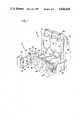
- FIG. 1is a perspective view of a fluid transfer device having a pump control system which embodies the features of the invention
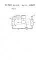
- FIG. 2is a diagrammatic view of the device and the associated pump control system
- FIG. 3is a flow diagram of one preferred embodiment of the weight evaluation circuit which forms a part of the pump control system of the invention.
- FIG. 4is a flow diagram of another preferred embodiment of the weight evaluation circuit.
- a fluid transfer device 10 having a pump control system 12 which embodies the features of the inventionis shown in FIG. 1.
- the pump control system 12serves to convey a desired amount of fluid from one or more supply containers 14, 16, and 18 into a collection container 20.
- the associated device 10is used to compound different hyperalimentation solutions from up to three supply containers 14, 16, and 18 into the collection container 20 for intravenous delivery to a patient.
- the device 10is similar in general operation to the one disclosed in Miller et al, U.S. patent application Ser. No. 391,759, now U.S. Pat. No. 4,513,796 filed June 24, 1982, and entitled, HIGH SPEED BULK COMPOUNDER.
- the device 10first conveys solution from the first source container 14 into the collection container 20 until a desired amount is delivered. The device 10 then conveys desired amounts of solution in sequence from each of the remaining second and third source containers 16 and 18. The result is a desired final mix of solutions in the collection container 20.
- Each supply container 14, 16, and 18communicates with the collection container 20 through a fluid transfer conduit, respectively 15, 17, and 19, which is preferably flexible tubing or the like. Fluid transfer is accomplished by pumps, respectively 22, 24, and 26, which are operatively connected to the conduits 15, 17, and 19 between each supply container 14, 16, and 18 and the receiving container 20.
- the pumps 22, 24, and 26can be of any positive fluid pumping type. Preferably, however, they are peristaltic pumps for use in sterile applications, as shown in FIG. 1.
- the device 10includes a pump module 28, on which the peristaltic pumps 22, 24, and 26 are mounted.
- the supply containers 14, 16, and 18are also suspended by hangers from a support bracket 30 on the pump module 28.
- the pump module 28also includes a weight sensor or detector 32, such as a conventional load cell, strain gauge or the like, on which the receiving container 20 is suspended.
- the device 10also includes a control module 34 which receives and supplies control signals from the pump module 28 through a control cable 36.
- the control module 34includes, for each of the supply containers 14, 16, and 18, a display, respectively 38, 40, and 42, which shows the desired volume of each solution which is to be conveyed into the collection container 20, along with a display, respectively 39, 41, and 43, which shows the specific gravity of such solution being conveyed.
- a display 45shows the volume amount of solution in the collection container 20.
- the control module 34also includes a keyboard 44 and associated data entry buttons 46, 48, and 50, through which the operator can enter the desired volume and specific gravity data into the displays 38, 40, and 42.
- weight-indicative voltage signalsare developed by conventional means by the weight sensor 32. These signals are conveyed to an amplifier 52 and an analog-to-digital converter 54. The weight-indicative voltage signals are fed through the amplifier 52 and converter 54 and are thereby converted by conventional means to digital weight-indicative signals.
- the pump control system 12includes a weight evaluation circuit 56, which receives the weight-indicative digital signals, and a pump operation circuit 58, which receives the output signals of the weight evaluation circuit 56 and drives the selected pump 22.
- the selected pumpis pump 22 associated with supply container 14 and flow tubing segment 15.
- FIG. 3where a flow diagram of a preferred embodiment of the weight evaluation circuit 56 is shown.
- the selected pump 22is initially operated in a continuous mode. During this mode, material is continuously conveyed from the associated supply container 14 into the collection container 20.
- the weight evaluation circuit 56continuously monitors the weight amount of material (W T ) present in the collection container 20.
- the continuous modeceases and an intermittent pumping mode begins.
- the active pump 22is preferably initially stopped for a predetermined time delay interval (T D ) to allow the weight sensor 32 to stabilize and provide an accurate weight-indicative output signal.
- T Dtime delay interval
- the active pump 22is next operated for a predetermined fixed time period (T F ).
- T Fa predetermined fixed time period
- W Ian incremental weight amount of material will be conveyed into the collection container 20.
- This incremental amount W Irepresents the difference between the weight of the container 20 at the beginning of the time period T F and the weight of the container 20 at the end of the time period T F .
- the fixed time period T Fis preferably purposely selected so that the incremental weight amount W I collected is less than the selected initial weight offset amount W O ; i.e., W I ⁇ W O .
- the end-point weight amount W Fis therefore purposely not the target of the circuit 56 at this stage of the intermittent mode.
- T FAfter the fixed time period T F has elapsed, the active pump 22 is again stopped.
- T Danother time delay (T D ) follows to allow the weight sensor 32 to again stabilize.
- the incremental weight amount W I which is collected during the fixed time period T Fis latched and retained by the circuit 56 for later use.
- this datais used to precisely control the subsequent delivery of material to the collection container 20 until the desired end-point weight amount W F is reached.
- the then-existing weight amount (W E ) of material present in the collection container 20is now compared to the desired end-point weight amount W F . If the then-existing weight W E is less than the desired end-point weight amount W F a present weight difference amount (W D ) is derived.
- the weight evaluation circuit 56next calculates a new time period (T C ) during which the active pump 22 will next be operated to convey additional material into the collection container 20.
- the weight evaluation circuit 56initially operates the active pump 22 for the fixed time period T F and measures the initial incremental weight amount W I as a prelude to deriving later, more precise control signals.
- the length of any subsequent time period (T C ) required to convey a desired increment weight amount of material (W D )is computed by the evaluation circuit 56 as follows:
- the weight evaluation circuit 56will not operate the active pump 22 for a time period which is less than a predetermined minimum (T MIN ) or exceeds a predetermined maximum (T MAX ), regardless of the magnitude of the calculated time period T C derived by the circuit 56 based upon then-existing conditions.
- T MINa predetermined minimum
- T MAXa predetermined maximum
- the minimum time period T MINserves to prevent stalling of the pump due to control signals of insufficient magnitude.
- the maximum time period T MAXserves, like the overshoot weight offset W B , to control the amount by which the circuit 56 can overshoot the desired end-point weight amount W F .
- the circuit 56compares T C both to the predetermined minimum time period T MIN and to the maximum time period T MAX . If the calculated time period T C exceeds the maximum time period T MAX , the active pump 22 is operated only for the maximum time period T MAX . If the calculated time period T C is less than the maximum time period T MAX , the active pump 22 is operated for either the calculated period T C or the minimum time period T MIN , whichever is greater.
- the active pump 22is operated either for the maximum time period T MAX , or the calculated time period T C , or the minimum time period T MIN , as appropriate. After another preferred time delay T D , the then-existing weight amount W E is again compared to the desired end-point weight amount W F . If the then-existing weight amount W E equals or exceeds the desired end-point weight amount W F , further operation of the active pump 22 is terminated. A new active pump 24, or 26 is selected and the heretofore described steps are repeated in their entirety.
- FIG. 4Another preferred embodiment is shown in FIG. 4. This embodiment is identical to the one shown in FIG. 3 and as heretofore described, except that, in each reiteration, the calculated time period T C and the corresponding incremental weight increase observed during the preceding iteration are used in place of T F and W I to calculate the new time period T C . In this embodiment, then, the circuit 56 is constantly adapting itself to the most recently observed flow characteristics of the device 10.
- the calculated time period T Crepresents the product of the fixed time period T F and the quotient of the present weight offset amount W D and the first incremental weight amount W I . Both W I and T C are retained by the circuit 56.
- the new calculated time period (New T C )represents the product of the preceding calculated time period (Last T C ) and the quotient of the present weight offset amount W D and the preceding incremental weight amount (Last W I ).
- the pump control system 12 as just describedmay be variously operated.
- the system 12in which the system 12 is used to precisely control the delivery of hyperalimentation solutions, the following system parameters can be used:
- the pump control system 12having the above listed system parameters was used to control delivery of various hyperalimentation solutions, and its speed, accuracy, and reliability were compared to the following conventional compounding methods:
- Vacuuma commercially available vacuum pumping unit
- the volumetric delivery accuracywas calculated from gravimetric and specific gravity data. The results are shown in the following Table 1.
- Table 1demonstrates that the system 12 which embodies the features of the invention is more accurate than any of the conventional methods studied.
- Table 2demonstrates that the system 12 which embodies the features of the invention was significantly the fastest method to compound three-component formulations.
Landscapes
- Physics & Mathematics (AREA)
- General Physics & Mathematics (AREA)
- Health & Medical Sciences (AREA)
- Nutrition Science (AREA)
- Chemical & Material Sciences (AREA)
- Medicinal Chemistry (AREA)
- Pharmacology & Pharmacy (AREA)
- Life Sciences & Earth Sciences (AREA)
- Animal Behavior & Ethology (AREA)
- General Health & Medical Sciences (AREA)
- Public Health (AREA)
- Veterinary Medicine (AREA)
- Weight Measurement For Supplying Or Discharging Of Specified Amounts Of Material (AREA)
Abstract
Description
W.sub.I /T.sub.F ≈W.sub.D /T.sub.C
T.sub.C ≈T.sub.F ·(W.sub.D /W.sub.I),
______________________________________ Initial Weight Offset 20 grams Amount (W.sub.O) Predetermined Time 750 milliseconds Delay Interval (T.sub.D) Fixed Time Period (T.sub.F) 500milliseconds Overshoot Prevention 1 gram Weight Offset (W.sub.B) Maximum Pump Time 750 milliseconds Period (T.sub.MAX) Minimum Pump Time 250 milliseconds Period (T.sub.MIN) ______________________________________
TABLE 1 ______________________________________ Volumetric Delivery Accuracy Mean % Volumetric Method error ±SD ______________________________________ System 12 0.45 ± 0.32 Vacuum 1.11 ± 1.00 Gravity 2.79 ± 1.54 Conventional Pump 5.12 ± 5.65 ______________________________________
TABLE 2 ______________________________________ Patient Specific Formula Compounding Time Required to Transfer Varied Amounts of Amino Acid, 50% Dextrose, and Water to an Empty Final Container (Three-Component Transfer) Mean Time ± SD Method Minutes ______________________________________System 12 1.15 ± 0.05 Conventional Pump 7.22 ± 0.38 Vacuum 9.62 ± 0.32 Gravity 23.40 ± 1.92 ______________________________________
Claims (15)
Priority Applications (1)
| Application Number | Priority Date | Filing Date | Title |
|---|---|---|---|
| US06/852,090US4648430A (en) | 1984-06-22 | 1986-04-14 | Device and method for collecting a desired weight amount of a material |
Applications Claiming Priority (2)
| Application Number | Priority Date | Filing Date | Title |
|---|---|---|---|
| US62381884A | 1984-06-22 | 1984-06-22 | |
| US06/852,090US4648430A (en) | 1984-06-22 | 1986-04-14 | Device and method for collecting a desired weight amount of a material |
Related Parent Applications (1)
| Application Number | Title | Priority Date | Filing Date |
|---|---|---|---|
| US62381884AContinuation | 1984-06-22 | 1984-06-22 |
Publications (1)
| Publication Number | Publication Date |
|---|---|
| US4648430Atrue US4648430A (en) | 1987-03-10 |
Family
ID=27089536
Family Applications (1)
| Application Number | Title | Priority Date | Filing Date |
|---|---|---|---|
| US06/852,090Expired - LifetimeUS4648430A (en) | 1984-06-22 | 1986-04-14 | Device and method for collecting a desired weight amount of a material |
Country Status (1)
| Country | Link |
|---|---|
| US (1) | US4648430A (en) |
Cited By (45)
| Publication number | Priority date | Publication date | Assignee | Title |
|---|---|---|---|---|
| US4789014A (en)* | 1986-12-05 | 1988-12-06 | Baxter International Inc. | Automated system for adding multiple fluids to a single container |
| US4922975A (en)* | 1986-01-24 | 1990-05-08 | Fresenius Ag | Apparatus for making mixtures of pharmaceutical liquids |
| US5040699A (en)* | 1989-05-15 | 1991-08-20 | Gangemi Ronald J | Fluid compounding method and apparatus |
| US5046569A (en)* | 1989-11-24 | 1991-09-10 | Sartorius Ag | Method and device for a pulsation-free, continuous and gravimetric dosing |
| US5056568A (en)* | 1986-12-05 | 1991-10-15 | Clintec Nutrition Company | Automated system for adding multiple fluids to a single container |
| US5076332A (en)* | 1986-12-08 | 1991-12-31 | Clintec Nitrition Co. | Arch geometry to eliminate tubing influence on load cell accuracy |
| US5402834A (en)* | 1992-11-25 | 1995-04-04 | Merck & Co., Inc. | Solution preparation system |
| US5431203A (en)* | 1993-08-12 | 1995-07-11 | R. M. Schultz & Associates, Inc. | Compressed gas tank filling system with improved valve |
| US5431202A (en)* | 1993-09-17 | 1995-07-11 | W. Cary Dikeman | Medical fluid flow control system and compounder apparatus |
| US5431201A (en)* | 1993-12-03 | 1995-07-11 | Technology 2000 Incororated | Robotic admixture system |
| US5450847A (en)* | 1991-04-22 | 1995-09-19 | Schering Aktiengesellschaft | Process for making doses formulation of contrast media from concentrate |
| US5458167A (en)* | 1993-08-12 | 1995-10-17 | R. M. Schultz & Associates, Inc. | Filling system for compressed gas tanks |
| US5464047A (en)* | 1994-01-24 | 1995-11-07 | Benjamin Moore & Co. | Method and apparatus for dispensing paint into containers |
| US5513678A (en)* | 1993-08-12 | 1996-05-07 | R. M. Schultz & Associates, Inc. | Filling system for compressed gas tanks |
| US5597094A (en)* | 1992-12-03 | 1997-01-28 | Solignac Industries S.A. | Device with peristaltic pump which makes it possible to draw, weight and mix liquids automatically |
| US5608650A (en)* | 1994-08-19 | 1997-03-04 | Spectrel Partners, L.L.C. | Systems and methods for testing pump flow rates |
| US5717603A (en)* | 1994-08-19 | 1998-02-10 | Spectrel Partners, L.L.C. | Integrated test station for testing liquid flow and electrical safety characteristics of IV pumps |
| US5742519A (en)* | 1994-08-19 | 1998-04-21 | Spectrel Partners, L.L.C. | Integrated systems for testing and certifying the physical, functional, and electrical performance of IV pumps |
| WO1998025570A1 (en)* | 1996-12-09 | 1998-06-18 | Baxter International Inc. | Compounding assembly for nutritional fluids |
| US6199603B1 (en) | 1998-08-14 | 2001-03-13 | Baxter International Inc. | Compounding assembly for nutritional fluids |
| US6213174B1 (en)* | 1998-04-17 | 2001-04-10 | Blue Boy International Limited | Portioning of flowable products |
| US6261065B1 (en) | 1999-09-03 | 2001-07-17 | Baxter International Inc. | System and methods for control of pumps employing electrical field sensing |
| US6296450B1 (en) | 1999-09-03 | 2001-10-02 | Baxter International Inc. | Systems and methods for control of pumps employing gravimetric sensing |
| US20030097232A1 (en)* | 1994-08-19 | 2003-05-22 | Triad Infusion Products, Inc. | Integrated systems for testing and certifying the physical, functional, and electrical performance of IV pumps |
| US6723062B1 (en) | 1999-09-03 | 2004-04-20 | Baxter International Inc. | Fluid pressure actuated blood pumping systems and methods with continuous inflow and pulsatile outflow conditions |
| US20040087888A1 (en)* | 2001-12-31 | 2004-05-06 | Digianfilippo Aleandro | Pharmaceutical compounding systems and methods and information management system for same |
| US6732597B1 (en) | 2002-11-14 | 2004-05-11 | Robert O. Brandt, Jr. | Precision gravimetric feeder |
| US20050086008A1 (en)* | 2001-12-31 | 2005-04-21 | Digianfilippo Aleandro | Apparatus and method for transferring data to a pharmaceutical compounding system |
| US20050126652A1 (en)* | 2003-12-04 | 2005-06-16 | Digianfilippo Aleandro | Bulk compounder manifold |
| US20050209737A1 (en)* | 1999-12-03 | 2005-09-22 | Kircher Joseph J | Method and apparatus for controlling the strategy of compounding pharmaceutical admixtures |
| US20050234385A1 (en)* | 1999-09-03 | 2005-10-20 | Baxter International Inc. | Blood processing systems with fluid flow cassette with a pressure actuated pump chamber and in-line air trap |
| US6984218B2 (en) | 1999-09-03 | 2006-01-10 | Baxter International Inc. | Systems and methods for control of pumps employing electrical field sensing |
| US20060054241A1 (en)* | 2004-09-16 | 2006-03-16 | Joel Bartholomew | By-pass line connector for compounding system |
| US20060130927A1 (en)* | 2001-12-31 | 2006-06-22 | Digianfilippo Aleandro | Pharmaceutical compounder |
| US20060259195A1 (en)* | 2004-12-22 | 2006-11-16 | Eliuk Walter W | Automated pharmacy admixture system (APAS) |
| US20080199353A1 (en)* | 2005-12-22 | 2008-08-21 | Intelligent Hospital Systems Ltd. | Ultraviolet Sanitization In Pharmacy Environments |
| US20090044877A1 (en)* | 2007-06-22 | 2009-02-19 | Jean-Yves Faudou | Method for controlled filling of pressurized gas tanks |
| US20090067973A1 (en)* | 2007-09-12 | 2009-03-12 | Intelligent Hospital Systems Ltd. | Gripper Device |
| US7610115B2 (en) | 2004-12-22 | 2009-10-27 | Intelligent Hospital Systems Ltd. | Automated pharmacy admixture system (APAS) |
| US20100241270A1 (en)* | 2009-03-18 | 2010-09-23 | Intelligent Hospital Systems Ltd. | Automated Pharmacy Admixture System |
| US8225824B2 (en) | 2007-11-16 | 2012-07-24 | Intelligent Hospital Systems, Ltd. | Method and apparatus for automated fluid transfer operations |
| FR2978064A1 (en)* | 2011-07-18 | 2013-01-25 | Interlab | METHOD AND DEVICE FOR GRAVIMETRIC DISTRIBUTION AND SOLUTION SERIES. |
| US20160310920A1 (en)* | 2015-04-23 | 2016-10-27 | B. Braun Medical Inc. | Compounding device, system, kit, software, and method |
| WO2016196810A1 (en)* | 2015-06-04 | 2016-12-08 | B. Braun Medical Inc. | Compounding device, system, kit, software, and method |
| US20240344872A1 (en)* | 2022-02-04 | 2024-10-17 | Zhengzhou Sanhua Technology & Industry Co., Ltd. | Liquid outpouring method and liquid outpouring device |
Citations (12)
| Publication number | Priority date | Publication date | Assignee | Title |
|---|---|---|---|---|
| US2199010A (en)* | 1936-01-03 | 1940-04-30 | John F Robb | Batching apparatus recording mechanism |
| US3306495A (en)* | 1964-06-02 | 1967-02-28 | American Motors Corp | Dispensing apparatus with calibrating means |
| DE2640842A1 (en)* | 1976-09-10 | 1978-03-23 | Linde Ag | Acetylene bottle filling system - with common valve for jointly filled batch controlled by weighing one bottle |
| US4182383A (en)* | 1978-06-23 | 1980-01-08 | General Electric Company | Fluidized bed powder discharge and metering method and apparatus |
| US4222496A (en)* | 1979-01-22 | 1980-09-16 | Fabri-Coate Company, Inc. | Continuous outflow, weight-measuring blender |
| US4272824A (en)* | 1979-08-17 | 1981-06-09 | Pennant Products, Inc. | Batch product preparation |
| US4275775A (en)* | 1978-05-12 | 1981-06-30 | Sig Schweizerische Industrie-Gesellschaft | System for the accurate dosing of bulk material |
| US4320855A (en)* | 1976-12-07 | 1982-03-23 | Acrison, Incorporated | Weigh feeding apparatus |
| US4401981A (en)* | 1981-11-27 | 1983-08-30 | Baxter Travenol Laboratories, Inc. | System for reading multiplexed data |
| US4408640A (en)* | 1981-10-26 | 1983-10-11 | The Singer Company | Method and apparatus for filling a container |
| US4438357A (en)* | 1982-06-17 | 1984-03-20 | Baxter Travenol Laboratories, Inc. | Level sensitive reset circuit for digital logic |
| US4582097A (en)* | 1983-10-05 | 1986-04-15 | Mateer-Burt Company, Inc. | Control apparatus and method for automatic filling machine |
- 1986
- 1986-04-14USUS06/852,090patent/US4648430A/ennot_activeExpired - Lifetime
Patent Citations (12)
| Publication number | Priority date | Publication date | Assignee | Title |
|---|---|---|---|---|
| US2199010A (en)* | 1936-01-03 | 1940-04-30 | John F Robb | Batching apparatus recording mechanism |
| US3306495A (en)* | 1964-06-02 | 1967-02-28 | American Motors Corp | Dispensing apparatus with calibrating means |
| DE2640842A1 (en)* | 1976-09-10 | 1978-03-23 | Linde Ag | Acetylene bottle filling system - with common valve for jointly filled batch controlled by weighing one bottle |
| US4320855A (en)* | 1976-12-07 | 1982-03-23 | Acrison, Incorporated | Weigh feeding apparatus |
| US4275775A (en)* | 1978-05-12 | 1981-06-30 | Sig Schweizerische Industrie-Gesellschaft | System for the accurate dosing of bulk material |
| US4182383A (en)* | 1978-06-23 | 1980-01-08 | General Electric Company | Fluidized bed powder discharge and metering method and apparatus |
| US4222496A (en)* | 1979-01-22 | 1980-09-16 | Fabri-Coate Company, Inc. | Continuous outflow, weight-measuring blender |
| US4272824A (en)* | 1979-08-17 | 1981-06-09 | Pennant Products, Inc. | Batch product preparation |
| US4408640A (en)* | 1981-10-26 | 1983-10-11 | The Singer Company | Method and apparatus for filling a container |
| US4401981A (en)* | 1981-11-27 | 1983-08-30 | Baxter Travenol Laboratories, Inc. | System for reading multiplexed data |
| US4438357A (en)* | 1982-06-17 | 1984-03-20 | Baxter Travenol Laboratories, Inc. | Level sensitive reset circuit for digital logic |
| US4582097A (en)* | 1983-10-05 | 1986-04-15 | Mateer-Burt Company, Inc. | Control apparatus and method for automatic filling machine |
Non-Patent Citations (2)
| Title |
|---|
| "A Comparative Evaluation of Methods Used to Compound Parenteral Nutrition Solutions", Nutritional Support Services, vol. 3, #12, 12/83, by Robert R. McClendon, RPh. |
| A Comparative Evaluation of Methods Used to Compound Parenteral Nutrition Solutions , Nutritional Support Services, vol. 3, 12, 12/83, by Robert R. McClendon, RPh.* |
Cited By (100)
| Publication number | Priority date | Publication date | Assignee | Title |
|---|---|---|---|---|
| US4922975A (en)* | 1986-01-24 | 1990-05-08 | Fresenius Ag | Apparatus for making mixtures of pharmaceutical liquids |
| US4967811A (en)* | 1986-12-05 | 1990-11-06 | Clintec Nutrition Company | Automated system for adding multiple fluids to a single container |
| US5056568A (en)* | 1986-12-05 | 1991-10-15 | Clintec Nutrition Company | Automated system for adding multiple fluids to a single container |
| US4789014A (en)* | 1986-12-05 | 1988-12-06 | Baxter International Inc. | Automated system for adding multiple fluids to a single container |
| US5076332A (en)* | 1986-12-08 | 1991-12-31 | Clintec Nitrition Co. | Arch geometry to eliminate tubing influence on load cell accuracy |
| US5040699A (en)* | 1989-05-15 | 1991-08-20 | Gangemi Ronald J | Fluid compounding method and apparatus |
| US5046569A (en)* | 1989-11-24 | 1991-09-10 | Sartorius Ag | Method and device for a pulsation-free, continuous and gravimetric dosing |
| US5450847A (en)* | 1991-04-22 | 1995-09-19 | Schering Aktiengesellschaft | Process for making doses formulation of contrast media from concentrate |
| US5592940A (en)* | 1991-04-22 | 1997-01-14 | Schering Aktiengesellschaft | Process for making doses formulation of contrast media from concentrate |
| US5402834A (en)* | 1992-11-25 | 1995-04-04 | Merck & Co., Inc. | Solution preparation system |
| US5597094A (en)* | 1992-12-03 | 1997-01-28 | Solignac Industries S.A. | Device with peristaltic pump which makes it possible to draw, weight and mix liquids automatically |
| US5431203A (en)* | 1993-08-12 | 1995-07-11 | R. M. Schultz & Associates, Inc. | Compressed gas tank filling system with improved valve |
| US5458167A (en)* | 1993-08-12 | 1995-10-17 | R. M. Schultz & Associates, Inc. | Filling system for compressed gas tanks |
| US5513678A (en)* | 1993-08-12 | 1996-05-07 | R. M. Schultz & Associates, Inc. | Filling system for compressed gas tanks |
| US5431202A (en)* | 1993-09-17 | 1995-07-11 | W. Cary Dikeman | Medical fluid flow control system and compounder apparatus |
| US5431201A (en)* | 1993-12-03 | 1995-07-11 | Technology 2000 Incororated | Robotic admixture system |
| US5464047A (en)* | 1994-01-24 | 1995-11-07 | Benjamin Moore & Co. | Method and apparatus for dispensing paint into containers |
| US5717603A (en)* | 1994-08-19 | 1998-02-10 | Spectrel Partners, L.L.C. | Integrated test station for testing liquid flow and electrical safety characteristics of IV pumps |
| US6757630B2 (en) | 1994-08-19 | 2004-06-29 | Mediq/Prn Life Support Services, Inc. | Integrated systems for testing and certifying the physical, functional, and electrical performance of IV pumps |
| US5742519A (en)* | 1994-08-19 | 1998-04-21 | Spectrel Partners, L.L.C. | Integrated systems for testing and certifying the physical, functional, and electrical performance of IV pumps |
| US5608650A (en)* | 1994-08-19 | 1997-03-04 | Spectrel Partners, L.L.C. | Systems and methods for testing pump flow rates |
| US5856929A (en)* | 1994-08-19 | 1999-01-05 | Spectrel Partners, L.L.C. | Integrated systems for testing and certifying the physical, functional, and electrical performance of IV pumps |
| US20030097232A1 (en)* | 1994-08-19 | 2003-05-22 | Triad Infusion Products, Inc. | Integrated systems for testing and certifying the physical, functional, and electrical performance of IV pumps |
| US5927349A (en)* | 1996-12-09 | 1999-07-27 | Baxter International Inc. | Compounding assembly for nutritional fluids |
| US6202711B1 (en) | 1996-12-09 | 2001-03-20 | Baxter International Inc. | Compounding assembly for nutritional fluids |
| WO1998025570A1 (en)* | 1996-12-09 | 1998-06-18 | Baxter International Inc. | Compounding assembly for nutritional fluids |
| US6213174B1 (en)* | 1998-04-17 | 2001-04-10 | Blue Boy International Limited | Portioning of flowable products |
| US6199603B1 (en) | 1998-08-14 | 2001-03-13 | Baxter International Inc. | Compounding assembly for nutritional fluids |
| US6261065B1 (en) | 1999-09-03 | 2001-07-17 | Baxter International Inc. | System and methods for control of pumps employing electrical field sensing |
| US6723062B1 (en) | 1999-09-03 | 2004-04-20 | Baxter International Inc. | Fluid pressure actuated blood pumping systems and methods with continuous inflow and pulsatile outflow conditions |
| US6296450B1 (en) | 1999-09-03 | 2001-10-02 | Baxter International Inc. | Systems and methods for control of pumps employing gravimetric sensing |
| US20050234385A1 (en)* | 1999-09-03 | 2005-10-20 | Baxter International Inc. | Blood processing systems with fluid flow cassette with a pressure actuated pump chamber and in-line air trap |
| US20060178612A9 (en)* | 1999-09-03 | 2006-08-10 | Baxter International Inc. | Blood processing systems with fluid flow cassette with a pressure actuated pump chamber and in-line air trap |
| US6984218B2 (en) | 1999-09-03 | 2006-01-10 | Baxter International Inc. | Systems and methods for control of pumps employing electrical field sensing |
| US20100057264A1 (en)* | 1999-12-03 | 2010-03-04 | Baxter International Inc. | Method and apparatus for controlling the compounding of a pharmaceutical admixture |
| US7620479B2 (en) | 1999-12-03 | 2009-11-17 | Baxter International Inc. | Method and apparatus for controlling the strategy of compounding pharmaceutical admixtures |
| US20050209737A1 (en)* | 1999-12-03 | 2005-09-22 | Kircher Joseph J | Method and apparatus for controlling the strategy of compounding pharmaceutical admixtures |
| US6975924B2 (en) | 1999-12-03 | 2005-12-13 | Baxter International Inc. | Method and apparatus for controlling the strategy of compounding pharmaceutical admixtures |
| US7194336B2 (en) | 2001-12-31 | 2007-03-20 | B. Braun Medical Inc. | Pharmaceutical compounding systems and methods with enhanced order entry and information management capabilities for single and/or multiple users and/or a network management capabilities for single and/or multiple users and/or a network |
| US7171992B2 (en) | 2001-12-31 | 2007-02-06 | B. Braun Medical Inc. | Pharmaceutical compounder |
| US20040087888A1 (en)* | 2001-12-31 | 2004-05-06 | Digianfilippo Aleandro | Pharmaceutical compounding systems and methods and information management system for same |
| US7343224B2 (en) | 2001-12-31 | 2008-03-11 | B. Braun Medical Inc. | Pharmaceutical compounding systems and methods and information management system for same |
| US7317967B2 (en) | 2001-12-31 | 2008-01-08 | B. Braun Medical Inc. | Apparatus and method for transferring data to a pharmaceutical compounding system |
| US20060130927A1 (en)* | 2001-12-31 | 2006-06-22 | Digianfilippo Aleandro | Pharmaceutical compounder |
| US20060136081A1 (en)* | 2001-12-31 | 2006-06-22 | Digianfilippo Aleandro | Pharmaceutical compounder and information management system |
| US20060133966A1 (en)* | 2001-12-31 | 2006-06-22 | Digianfilippo Aleandro | Transfer set for use with a pharmaceutical compounder |
| US20050086008A1 (en)* | 2001-12-31 | 2005-04-21 | Digianfilippo Aleandro | Apparatus and method for transferring data to a pharmaceutical compounding system |
| US6732597B1 (en) | 2002-11-14 | 2004-05-11 | Robert O. Brandt, Jr. | Precision gravimetric feeder |
| US20040093958A1 (en)* | 2002-11-14 | 2004-05-20 | Brandt Robert O. | Precision gravimetric feeder |
| US6951228B2 (en) | 2003-12-04 | 2005-10-04 | B Braun Medical Inc. | Bulk compounder manifold |
| US7252122B2 (en) | 2003-12-04 | 2007-08-07 | B. Braun Medical Inc. | Bulk compounder manifold |
| US20050126652A1 (en)* | 2003-12-04 | 2005-06-16 | Digianfilippo Aleandro | Bulk compounder manifold |
| US20060070684A1 (en)* | 2003-12-04 | 2006-04-06 | Digianfilippo Aleandro | Bulk compounder manifold |
| US7036537B2 (en) | 2003-12-04 | 2006-05-02 | B. Braun Medical Inc. | Bulk compounder manifold |
| US20070151626A1 (en)* | 2004-09-16 | 2007-07-05 | Joel Bartholomew | By-pass line connector for compounding system |
| US7836920B2 (en) | 2004-09-16 | 2010-11-23 | B. Braun Medical, Inc. | By-pass line connector for compounding system |
| US20070151618A1 (en)* | 2004-09-16 | 2007-07-05 | Joel Bartholomew | By-pass line connector for compounding system |
| US20060054241A1 (en)* | 2004-09-16 | 2006-03-16 | Joel Bartholomew | By-pass line connector for compounding system |
| US7415994B2 (en) | 2004-09-16 | 2008-08-26 | B.Braun Medical, Inc. | By-pass line connector for compounding system |
| US20080283146A1 (en)* | 2004-09-16 | 2008-11-20 | B.Braun Medical, Inc. | By-pass line connector for compounding system |
| US7490636B2 (en) | 2004-09-16 | 2009-02-17 | B. Braun Medical Inc. | By-pass line connector for compounding system |
| US7726361B2 (en) | 2004-09-16 | 2010-06-01 | B. Braun Medical, Inc. | By-pass line connector for compounding system |
| US7204277B2 (en) | 2004-09-16 | 2007-04-17 | B. Braun Medical Inc. | By-pass line connector for compounding system |
| US20100032052A1 (en)* | 2004-09-16 | 2010-02-11 | B. Braun Medical, Inc. | By-pass line connector for compounding system |
| US7783383B2 (en) | 2004-12-22 | 2010-08-24 | Intelligent Hospital Systems Ltd. | Automated pharmacy admixture system (APAS) |
| US7610115B2 (en) | 2004-12-22 | 2009-10-27 | Intelligent Hospital Systems Ltd. | Automated pharmacy admixture system (APAS) |
| US20060259195A1 (en)* | 2004-12-22 | 2006-11-16 | Eliuk Walter W | Automated pharmacy admixture system (APAS) |
| US20080199353A1 (en)* | 2005-12-22 | 2008-08-21 | Intelligent Hospital Systems Ltd. | Ultraviolet Sanitization In Pharmacy Environments |
| US7931859B2 (en) | 2005-12-22 | 2011-04-26 | Intelligent Hospital Systems Ltd. | Ultraviolet sanitization in pharmacy environments |
| US20090044877A1 (en)* | 2007-06-22 | 2009-02-19 | Jean-Yves Faudou | Method for controlled filling of pressurized gas tanks |
| US8286670B2 (en) | 2007-06-22 | 2012-10-16 | L'air Liquide Societe Anonyme Pour L'etude Et L'exploitation Des Procedes Georges Claude | Method for controlled filling of pressurized gas tanks |
| US20090067973A1 (en)* | 2007-09-12 | 2009-03-12 | Intelligent Hospital Systems Ltd. | Gripper Device |
| US8271138B2 (en) | 2007-09-12 | 2012-09-18 | Intelligent Hospital Systems Ltd. | Gripper device |
| US8225824B2 (en) | 2007-11-16 | 2012-07-24 | Intelligent Hospital Systems, Ltd. | Method and apparatus for automated fluid transfer operations |
| US20100241270A1 (en)* | 2009-03-18 | 2010-09-23 | Intelligent Hospital Systems Ltd. | Automated Pharmacy Admixture System |
| US8386070B2 (en) | 2009-03-18 | 2013-02-26 | Intelligent Hospital Systems, Ltd | Automated pharmacy admixture system |
| FR2978064A1 (en)* | 2011-07-18 | 2013-01-25 | Interlab | METHOD AND DEVICE FOR GRAVIMETRIC DISTRIBUTION AND SOLUTION SERIES. |
| US20180043323A1 (en)* | 2015-04-23 | 2018-02-15 | B. Braun Medical Inc. | Compounding device, system, kit, software, and method |
| AU2021200220B2 (en)* | 2015-04-23 | 2022-12-01 | B. Braun Medical Inc. | Compounding device, system, kit, software, and method |
| US12370355B2 (en) | 2015-04-23 | 2025-07-29 | B.Braun Medical Inc. | Compounding device, system, kit, software, and method |
| US9802172B2 (en)* | 2015-04-23 | 2017-10-31 | B. Braun Medical Inc. | Compounding device, system, kit, software, and method |
| US20160310920A1 (en)* | 2015-04-23 | 2016-10-27 | B. Braun Medical Inc. | Compounding device, system, kit, software, and method |
| CN108093654A (en)* | 2015-04-23 | 2018-05-29 | B.布劳恩医疗公司 | Composite devices, systems, toolkits, software and methods |
| US10143985B2 (en)* | 2015-04-23 | 2018-12-04 | B. Braun Medical Inc. | Compounding device, system, kit, software, and method |
| US10512885B2 (en) | 2015-04-23 | 2019-12-24 | B. Braun Medical Inc. | Compounding device, system, kit, software, and method |
| US12076524B2 (en) | 2015-04-23 | 2024-09-03 | B. Braun Medical Inc. | Compounding device, system, kit, software, and method |
| CN108093654B (en)* | 2015-04-23 | 2020-02-21 | B.布劳恩医疗公司 | Composite device, system, toolbox, software and method |
| US10617863B2 (en) | 2015-04-23 | 2020-04-14 | B. Braun Medical Inc. | Compounding device, system, kit, software, and method |
| US11957864B2 (en) | 2015-04-23 | 2024-04-16 | B. Braun Medical Inc. | Compounding device, system, kit, software, and method |
| US10709885B2 (en)* | 2015-04-23 | 2020-07-14 | B. Braun Medical Inc. | Compounding device, system, kit, software, and method |
| AU2016270941B2 (en)* | 2015-04-23 | 2021-02-25 | B. Braun Medical Inc. | Compounding device, system, kit, software, and method |
| US11357966B2 (en) | 2015-04-23 | 2022-06-14 | B. Braun Medical Inc. | Compounding device, system, kit, software, and method |
| AU2021200225B2 (en)* | 2015-04-23 | 2022-12-01 | B. Braun Medical Inc. | Compounding device, system, kit, software, and method |
| US20160310916A1 (en)* | 2015-04-23 | 2016-10-27 | B. Braun Medical Inc. | Compounding device, system, kit, software, and method |
| US11717668B2 (en) | 2015-04-23 | 2023-08-08 | B. Braun Medical Inc. | Compounding device, system, kit, software, and method |
| EP3607930A3 (en)* | 2015-06-04 | 2020-04-15 | B. Braun Medical Inc. | Compounding device, system, kit, software and method |
| EP3586812A1 (en)* | 2015-06-04 | 2020-01-01 | B. Braun Medical Inc. | Compounding device, system, kit, software and method |
| WO2016196810A1 (en)* | 2015-06-04 | 2016-12-08 | B. Braun Medical Inc. | Compounding device, system, kit, software, and method |
| US20240344872A1 (en)* | 2022-02-04 | 2024-10-17 | Zhengzhou Sanhua Technology & Industry Co., Ltd. | Liquid outpouring method and liquid outpouring device |
| US12339150B2 (en)* | 2022-04-02 | 2025-06-24 | Zhengzhou Sanhua Technology & Industry Co., Ltd. | Liquid outpouring method and liquid outpouring device |
Similar Documents
| Publication | Publication Date | Title |
|---|---|---|
| US4648430A (en) | Device and method for collecting a desired weight amount of a material | |
| US4670007A (en) | Fluid flow control process and apparatus | |
| US12115344B2 (en) | Occlusion detection system and method | |
| JP6534633B2 (en) | Infusion pump with tube measurement technology using linear actuator and pressure sensor | |
| US4919596A (en) | Fluid delivery control and monitoring apparatus for a medication infusion system | |
| EP0319267B1 (en) | Fluid delivery control and monitoring apparatus | |
| US4781525A (en) | Flow measurement system | |
| JP2527527B2 (en) | Method and apparatus for pressure determination and occlusion detection in syringe pumps | |
| US20040176720A1 (en) | Device for administering a liquid solution of an active substance | |
| US4952205A (en) | Pressure infusion device | |
| US20030045840A1 (en) | Intravenous set flow volumetric measurement device | |
| WO1990007942A1 (en) | A method of continuous monitoring of the operation of a delivery system, a device for carrying out this method, and the use of this device | |
| CA1239630A (en) | Device and method for collecting a desired weight amount of a material | |
| US5085256A (en) | Drift stabilization check | |
| JP2963514B2 (en) | Infusion control device | |
| JP2003294519A (en) | Method for measuring amount of feed in continuous powder feeder | |
| EP3801679B1 (en) | Infusing pumping system including disposable cassette and pump | |
| JPH0116507B2 (en) | ||
| HK40002022A (en) | Method for preparing a medical preparation | |
| HK40002022B (en) | Method for preparing a medical preparation | |
| HK40002035B (en) | Method for producing a medical preparation using a hose pump | |
| HK40002035A (en) | Method for producing a medical preparation using a hose pump | |
| JPH02270712A (en) | Constant payout amount control system | |
| AU2015224423A1 (en) | Infusion pump with tube measurement technique using linear actuator and pressure sensor |
Legal Events
| Date | Code | Title | Description |
|---|---|---|---|
| STCF | Information on status: patent grant | Free format text:PATENTED CASE | |
| FPAY | Fee payment | Year of fee payment:4 | |
| FEPP | Fee payment procedure | Free format text:PAYOR NUMBER ASSIGNED (ORIGINAL EVENT CODE: ASPN); ENTITY STATUS OF PATENT OWNER: LARGE ENTITY | |
| AS | Assignment | Owner name:CLINTEC NUTRITION COMPANY, ILLINOIS Free format text:ASSIGNMENT OF ASSIGNORS INTEREST.;ASSIGNOR:BAXTER INTERNATIONAL INC.;REEL/FRAME:006327/0970 Effective date:19921005 | |
| FPAY | Fee payment | Year of fee payment:8 | |
| AS | Assignment | Owner name:BAXTER INTERNATIONAL INC., ILLINOIS Free format text:ASSIGNMENT OF ASSIGNORS INTEREST;ASSIGNOR:CLINTEC NUTRITION COMPANY;REEL/FRAME:008239/0827 Effective date:19961001 | |
| FEPP | Fee payment procedure | Free format text:PAYOR NUMBER ASSIGNED (ORIGINAL EVENT CODE: ASPN); ENTITY STATUS OF PATENT OWNER: LARGE ENTITY Free format text:PAYER NUMBER DE-ASSIGNED (ORIGINAL EVENT CODE: RMPN); ENTITY STATUS OF PATENT OWNER: LARGE ENTITY | |
| FPAY | Fee payment | Year of fee payment:12 |