US4647917A - Article control system having coded magnetomechanical marker - Google Patents
Article control system having coded magnetomechanical markerDownload PDFInfo
- Publication number
- US4647917A US4647917AUS06/593,146US59314684AUS4647917AUS 4647917 AUS4647917 AUS 4647917AUS 59314684 AUS59314684 AUS 59314684AUS 4647917 AUS4647917 AUS 4647917A
- Authority
- US
- United States
- Prior art keywords
- marker
- generating
- interrogation zone
- code
- control system
- Prior art date
- Legal status (The legal status is an assumption and is not a legal conclusion. Google has not performed a legal analysis and makes no representation as to the accuracy of the status listed.)
- Expired - Lifetime
Links
Images


Classifications
- G—PHYSICS
- G08—SIGNALLING
- G08B—SIGNALLING OR CALLING SYSTEMS; ORDER TELEGRAPHS; ALARM SYSTEMS
- G08B13/00—Burglar, theft or intruder alarms
- G08B13/22—Electrical actuation
- G08B13/24—Electrical actuation by interference with electromagnetic field distribution
- G08B13/2402—Electronic Article Surveillance [EAS], i.e. systems using tags for detecting removal of a tagged item from a secure area, e.g. tags for detecting shoplifting
- G08B13/2405—Electronic Article Surveillance [EAS], i.e. systems using tags for detecting removal of a tagged item from a secure area, e.g. tags for detecting shoplifting characterised by the tag technology used
- G08B13/2408—Electronic Article Surveillance [EAS], i.e. systems using tags for detecting removal of a tagged item from a secure area, e.g. tags for detecting shoplifting characterised by the tag technology used using ferromagnetic tags
- G—PHYSICS
- G06—COMPUTING OR CALCULATING; COUNTING
- G06K—GRAPHICAL DATA READING; PRESENTATION OF DATA; RECORD CARRIERS; HANDLING RECORD CARRIERS
- G06K19/00—Record carriers for use with machines and with at least a part designed to carry digital markings
- G06K19/06—Record carriers for use with machines and with at least a part designed to carry digital markings characterised by the kind of the digital marking, e.g. shape, nature, code
- G06K19/067—Record carriers with conductive marks, printed circuits or semiconductor circuit elements, e.g. credit or identity cards also with resonating or responding marks without active components
- G06K19/0672—Record carriers with conductive marks, printed circuits or semiconductor circuit elements, e.g. credit or identity cards also with resonating or responding marks without active components with resonating marks
- G—PHYSICS
- G06—COMPUTING OR CALCULATING; COUNTING
- G06K—GRAPHICAL DATA READING; PRESENTATION OF DATA; RECORD CARRIERS; HANDLING RECORD CARRIERS
- G06K7/00—Methods or arrangements for sensing record carriers, e.g. for reading patterns
- G06K7/08—Methods or arrangements for sensing record carriers, e.g. for reading patterns by means detecting the change of an electrostatic or magnetic field, e.g. by detecting change of capacitance between electrodes
- G06K7/082—Methods or arrangements for sensing record carriers, e.g. for reading patterns by means detecting the change of an electrostatic or magnetic field, e.g. by detecting change of capacitance between electrodes using inductive or magnetic sensors
- G06K7/083—Methods or arrangements for sensing record carriers, e.g. for reading patterns by means detecting the change of an electrostatic or magnetic field, e.g. by detecting change of capacitance between electrodes using inductive or magnetic sensors inductive
- G06K7/086—Methods or arrangements for sensing record carriers, e.g. for reading patterns by means detecting the change of an electrostatic or magnetic field, e.g. by detecting change of capacitance between electrodes using inductive or magnetic sensors inductive sensing passive circuit, e.g. resonant circuit transponders
- G—PHYSICS
- G08—SIGNALLING
- G08B—SIGNALLING OR CALLING SYSTEMS; ORDER TELEGRAPHS; ALARM SYSTEMS
- G08B13/00—Burglar, theft or intruder alarms
- G08B13/22—Electrical actuation
- G08B13/24—Electrical actuation by interference with electromagnetic field distribution
- G08B13/2402—Electronic Article Surveillance [EAS], i.e. systems using tags for detecting removal of a tagged item from a secure area, e.g. tags for detecting shoplifting
- G08B13/2451—Specific applications combined with EAS
- G08B13/2462—Asset location systems combined with EAS
- G—PHYSICS
- G08—SIGNALLING
- G08B—SIGNALLING OR CALLING SYSTEMS; ORDER TELEGRAPHS; ALARM SYSTEMS
- G08B13/00—Burglar, theft or intruder alarms
- G08B13/22—Electrical actuation
- G08B13/24—Electrical actuation by interference with electromagnetic field distribution
- G08B13/2402—Electronic Article Surveillance [EAS], i.e. systems using tags for detecting removal of a tagged item from a secure area, e.g. tags for detecting shoplifting
- G08B13/2465—Aspects related to the EAS system, e.g. system components other than tags
- G08B13/2468—Antenna in system and the related signal processing
- G08B13/2471—Antenna signal processing by receiver or emitter
- G—PHYSICS
- G08—SIGNALLING
- G08B—SIGNALLING OR CALLING SYSTEMS; ORDER TELEGRAPHS; ALARM SYSTEMS
- G08B13/00—Burglar, theft or intruder alarms
- G08B13/22—Electrical actuation
- G08B13/24—Electrical actuation by interference with electromagnetic field distribution
- G08B13/2402—Electronic Article Surveillance [EAS], i.e. systems using tags for detecting removal of a tagged item from a secure area, e.g. tags for detecting shoplifting
- G08B13/2465—Aspects related to the EAS system, e.g. system components other than tags
- G08B13/2468—Antenna in system and the related signal processing
- G08B13/2474—Antenna or antenna activator geometry, arrangement or layout
Definitions
- the inventionrelates to an article control system and an encoded marker used therein, and more particularly, to a system in which an article of luggage having an encoded marker attached thereto is monitored from a remote location and thus guided to a proper destination.
- Article control systemsupon which this invention has improved, are conventionally employed in applications where articles of luggage are required to be transferred to many different locations. There presently exists two main categories of such systems: manual and automated.
- Manual article control systemsentail affixing a label containing a destination code and/or address directly to an article and thereafter visually reading the affixed label to determine the proper routing required to allow the article to reach its proper destination.
- Such systemsare personnel dependent, thus in applications where large volumes of articles are transferred to many different locations human error or misreading of labels becomes increasingly detrimental to the efficiency of the system.
- visually reading the affixed labelrequires correct positioning and the proper lighting of the article.
- tags or bar codescontain inscripted information about the article such as a name, address or destination.
- An article to which a tag or bar code is affixed upon passing by a visual scannerconveys its inscripted information to a signal generating device enabling a routing mechanism to guide the article to its proper destination.
- the major drawbacks of these tags or codesis that they require proper orientation of the color coded tag or bar code to the visual scanner and any obstruction between the tag or code and the scanner disables the system. As a result of this such automated article control system are less efficient and reliable than expected.
- the present inventionprovides an article control system that allows an article to which an encoded marker is attached to be remotely monitored and/or guided to a proper destination.
- the coded markerremains functional regardless of the orientation of the article to which it is attached and, more surprisingly, the marker requires no power or physical contact with the system's sensing devices.
- the article control system of the inventioncomprises means for defining an interrogation zone.
- the systemhas a generating means, including an interrogating coil, for generating a magnetic field having a frequency band within the interrogation zone and a marker associated with an article appointed for passage through the interrogation zone.
- the markeris responsive within the interrogation zone to undergo a substantial change in its effective magnetic permeability at preselected frequencies within the frequency band that provides the marker with signal identity.
- the markercomprises at least one strip of magnetostrictive, ferromagnetic material. The strip is adapted to be magnetically biased and thereby armed to resonate mechanically at a preselected frequency with the frequency band of the magnetic field.
- the systemhas a detecting means for detecting the resonance of the marker within the interrogation zone.
- a cataloging meansis provided for maintaining a code list comprising at least one predefined code, which is generated by a code entry means.
- the systemalso includes a decoding means for comparing the detected marker resonance against the code list to verify parity between said resonance and said predefined code.
- the systementails a signal means for generating a signal in response to an indication of parity from the decoding means
- the article control system of the inventionprovides added security against theft and/or accidental loss of articles as a benefit of having a remotely detected marker whose code is not externally visible.
- FIG. 1is a block diagram of an article surveillance system incorporating the present invention
- FIG. 2is a diagrammatic illustration of a typical installation of the system of FIG. 1;
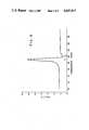
- FIG. 3is a graph showing the voltage induced by magnetomechanical energy exchange of an article control marker over a preselected frequency range
- FIG. 4is a isometric view showing components of a marker adapted for use in the system of FIG. 1;
- FIG. 5is an isometric view showing a portable unit of the system of FIG. 1;
- FIG. 6is a schematic electrical diagram of an interrogation and detection scheme comprising part of the article control system of FIG. 1.
- the components of the article control system 10can be fabricated in a number of diverse sizes and configurations.
- the inventionhas been found to function with many varieties of article control systems.
- the inventionis described in connection with an article control system in which the monitored and/or guided articles are items of luggage passing through an airport to which coded markers have been attached allowing more efficient and reliable transferring of such items to their proper destinations.
- the inventioncan be employed for similar and yet diversified uses, such as the identification of articles, wherein the marker and the system exchange magnetomechanical energy so that the marker functions as an identifier for checkpoint control of classified documents, warehouse packages, library books and the like.
- the inventionis intended to encompass modifications of the preferred embodiment wherein at least one resonant frequency of the marker provides articles bearing it with signal identity.
- FIG. 1 of the drawingsthere is shown an article control system 10 responsive to the presence of an article within an interrogation zone.
- the system 10has means for defining an interrogation zone 12.
- a field generating means 14is provided for generating a magnetic field having a frequency band within the interrogation zone 12.
- the system 10provides a marker 16 associated with an article 17 which is responsive within the interrogation zone 12 to undergo a substantial change in its effective magnetic permeability at preselected frequencies within the frequency band that provides the marker 16 with signal identity.
- a detecting means 20is also provided for detecting resonance of said marker within the interrogation zone 12.
- a cataloging means 210is provided for maintaining a code list comprising at least one predefined code which is generated by a code entry means 200.
- the system 10also includes a decoding means 15 for comparing the detected marker resonances against the code list to verify parity between said resonances and said predefined code.
- the systementails a signal means 220 for generating a signal in response to an indication of parity from the deooding means 15.
- FIG. 2 of the drawingsis a diagrammatic illustration of an article control system installed in an airport where incoming articles 17 labeled luggage from passengers must be monitored and/or guided to the proper airplane whose destination matches that of the passenger.
- a passenger and luggage 17arrive at an airport and proceed to the reservation desk 70.
- the reservation desk 70is that local at which the passenger's flight reservations are confirmed and the luggage 17 is prepared for transit to the airplane's luggage compartment.
- a marker 16is attached to the luggage 17.
- the code of marker 16is then entered via code entry means 200 to the cataloging means 210, which correlates the entered code with the passenger's name and destination.
- the luggage 17 with attached marker 16is then placed on conveyor 230, which transports luggage 17 towards the airplane cargo loading area. As shown in FIG.
- the main conveyor belt 230proceeds past three gates A, B and C which are connected to individual conveyor belts A (not shown), B and C, each of which leads to a different airplane cargo loading area A (not shown), B or C.
- the generating means 14, interrogating coil 72 and a receiving coil 74 of the detecting means 20are located on opposite sides of the conveyor belt 230 providing an interrogation zone 12 located prior to the first gate C.
- the marker 16 upon entering the interrogation zone 12is characterized by a substantial change in its effective magnetic permeability at the resonant and/or antiresonant frequency (shown in FIG. 3 as fr and fa) of which each of the predefined frequencies are comprised that provides marker 16 with signal identity.
- the detecting means 20then detects the resonant frequencies at which the marker 16 undergoes the substantial change in effective magnetic permeability. These frequencies are then relayed to the decoding means 15 which compares the detected marker 16 resonances against a code list relayed from the cataloging means 210 and upon finding a predefined code that matches the marker's 16 resonances, the decoding means 20 relays a corresponding code from the code list to the signal means 220 (FIG. 1).
- the signal means 220is a series of three gates A, B and C, each of which responds by opening to a different code relayed from the decoding means 15.
- the gatecloses allowing the signal means 220 to respond to the next code received from the decoding means 15.
- the marker 16(FIG. 4) is comprised of at least one strip 18 of amorphous magnetostrictive ferromagnetic material enclosed within a container 19 composed of a ferromagnetic filled plastic such as polyester filled with barium ferrite.
- Container 19consists of two parts: a boat 62 and a cover 44. The container must be constructed in such a manner that strip 18 remains undamped or free to vibrate, upon being placed in the boat 62 and enclosed by the cover 44. This can be accomplished by leaving 1 millimeter clearance on all inside dimensions of container 19.
- the container 19is adapted, upon being magnetized, to magnetically bias the strip 18 and thereby arm the strip 18 to resonate at its preselected frequency.
- the markeris composed of a magnetostrictive amorphous metal alloy in the form a strip 18 having a first component composed of a composition consisting essentially of the formula M a N b O c X d Y e Z f , where M is at least one of iron and cobalt, N is nickel, O is at least one of chromium and molybdenum, X is at least one of boron and phosphorous, Y is silicon, Z is carbon, "a”-"f” are in atom percent, “a” ranges from about 35-85, “b” ranges from about 0-45, “c” ranges from about 0-7, “d” ranges from about 5-22, “e” ranges from about 0-15 and “f” ranges from about 0-2, and the sum of d+e+f ranges from about 15-25.
- the marker 16is designed in such a manner as to allow numerous codes to be represented. Coded markers having the structure of marker 16 are visually indistinguishable from one
- the code entry means 200 for generating a code listcan be actuated by several different methods.
- One methodconsists of a keyboard wherein the code is visually read from markings on the marker 16 and then entered by pressing corresponding buttons on the keyboard in the correct sequence.
- the marker's 16 codemay be entered by voice demodulation in which markings on the marker 16 are transposed to verbal communication and then demodulated to an electronic representation.
- an electronic signalsuch as that created by detecting the resonances of marker 16 or by communication via a modem can be used to enter the markers code.
- the cataloging means 210for maintaining a code list, correlates the code of marker 16 to information on the luggage 17 to which it is attached such as destination code, identification codes and/or routing codes.
- the cataloging means 210receives the markers 16 code from the code entry means 200 and upon verification of the passengers reservations the additional information codes are received via an electronic terminal. Upon request the cataloging means 210 transmits the code list to the decoding means 15 via an electronic signal.
- the decoding means 15searches the code list, from the cataloging means 210, for a code that matches the detected marker's 16 code, from the detecting means 20. Upon finding a matching pair of codes the decoding means 15 transmits a corresponding code such as a destination code to the signal means 220. The signal means 220 then produces a physical response which is individually keyed to the received code such as opening a specific gate and/or lighting corresponding lights.
- the generating means 14is comprised of an energizing circuit 201 (FIG. 6) and an interrogation coil 206.
- the energizing circuit 201 in the preferred embodimentis adapted to provide the interrogating coil 206 with a burst of sine wave frequencies that includes each the marker's preselected frequencies.
- energizing meanswhich provide the marker 16 with each of its preselected frequencies, including (1) a frequency sweeping means adapted to sweep through each different preselected frequency of the marker 16, (2) an energizing means adapted to provide the interrogating coil 206 with a pulse, the width of which is equal to 1/(2 fr), where fr is the preselected frequency (3) an energizing means adapted to provide the interrogating coil 206 with a burst of noise and (4) an energizing means adapted to provide the interrogation coil 206 with a burst of sweeping sine wave frequency.
- the generating means 14provides a burst of sine wave frequencies. Upon completion of the burst the marker 16 will continue to vibrate and thereby undergo damped oscillation at its resonance frequencies. The vibrating marker 16 will cause a voltage to be induced in the receiving coil 207 of the detection means 20 at each of the resonant frequencies.
- the detecting means 20is synchronized with the generating means 14 via synchronizing circuit 209 in such a manner as to allow the resonant frequencies induced in the receiving coil 207 to be detected only after completion of the interrogating burst.
- the detecting means 20determines the values, via the detecting circuit 202, of the resonant frequencies of the marker 16 and thus produces a frequency code.
- the frequency codeis transmitted to the decoding means 15 for comparison with the code list.
- the article control system 5 in FIG. 5is designed as a portable unit capable of locating a specific item of luggage located in the presence of many other items of luggage.
- the method of operationis the same as previously described, however, the configuration is slightly altered.
- the antenna system 340 of FIG. 5is constructed as a hand held unit consisting of a pair of interrogation coils 350, 351 disposed adjacent and coplanar to each other and driven alternately at phase angles of 0° and 180° with respect to each other.
- a receiving coil 352is positioned coplanar and centered about the interrogation coils 350, 351.
- the complete antenna system 340is encased within a nonmagnetic binder with an attached handle through which linking means with the electronics of system 5 are placed.
- the electronics of system 5are located within a portable box which enables the code of the specific luggage to be entered via a keypad 363 thereon. Upon positioning the antenna system 340 in the vicinity of the specific luggage a signal is produced such as a flashing light, 370. Thus system 5 enables a desired item of luggage with affixed marker to be located efficiently and quickly.
- markers 16 containing strips 18, or magnetostrictive amorphous materialare particularly adapted to resonate mechanically at preselected frequencies of an incident magnetic field. While we do to wish to be bound by any theory, it is believed that, in markers of the aforesaid composition, direct magnetic coupling between an ac magnetic field and the marker 16 occurs by means of the following mechanism.
- a ferromagnetic materialsuch as an amorphous metal ribbon
- Hmagnetic field
- the ribbon's magnetic domainsare caused to grow and/or rotate. This domain movement allows magnetic energy to be stored, in addition to a small amount of energy which is lost as heat.
- the domainsreturn to their original orientation releasing the stored magnetic energy, again minus a small amount of energy lost as heat.
- Amorphous metalhave high efficiency in this mode of energy storage. Since amorphus metals have no grain boundaries and have high resistivities, their energy losses are extraordinarily low.
- a magnetostrictive amorphous metal ribbonWhen the ferromagnetic ribbon is magnetostrictive, an additional mode of energy storage is also possible.
- This additional mode of energy storagemay be viewed as an increase in the effective magnetic permeability of the ribbon.
- magnetostrictive ribbonWhen an ac magnetic field and a dc field are introduced on the magnetostrictive ribbon (such as can be generated by ac and dc electric currents in a solenoid), energy is alternately stored and released with the frequency of the ac field.
- the magnetostrictive energy storage and releaseare maximal at the material's mechanical resonance frequency and minimal at its anti-resonance. This energy storage and release induces a voltage in a pickup coil via flux density changes in the ribbon.
- the flux density changemay also be viewed as an increase in effective magnetic permeability at the resonant frequency and a decrease at antiresonance, thus, in effect, increasing or decreasing, respectively, the magnetic coupling between the driving solenoid and a second pickup solenoid.
- the voltage induced by the purely magnetic energy exchangeis linear with frequency and the change in voltage with frequency is small over a limited frequency range.
- the voltage induced by the magnetomechanical energy exchangeis also linear with frequency except near mechanical resonance.
- the mechanical resonance frequencyis given by:
- MMCmagnetomechanical coupling
- kthe ratio of mechanical to magnetic energy.
- fr and faare, respectively, the resonant and anti-resonant frequencies described above.
- fr and faare, respectively, the resonant and anti-resonant frequencies described above.
- fr and faare, respectively, the resonant and anti-resonant frequencies described above.
- fr and faare, respectively, the resonant and anti-resonant frequencies described above.
- fr and faare, respectively, the resonant and anti-resonant frequencies described above.
- fr and faare, respectively, the resonant and anti-resonant frequencies described above.
- fr and faare, respectively, the resonant and anti-resonant frequencies described above.
- fr and faare, respectively, the resonant and anti-resonant frequencies described above.
- fr and faare, respectively, the resonant and anti-resonant frequencies described above.
- Coupling factorsare influenced in a given amorphous metal by the level of bias field present, the level of internal stress (or structural anisotropy) present and by the level and direction of any magnetic anisotropy.
- Annealing an amorphous metalrelieves internal stresses, thus enhancing k.
- the structural anisotropyis small due to the ribbon's amorphous nature, also enhancing k.
- Annealing in a properly oriented magnetic fieldcan significantly enhance coupling factors. Domain movement can be maximized when the ribbon has a magnetic anisotropy which is perpendicular to the interrogating field. Because of demagnetizing field effects, it is practical to interrogate the ribbon only along its length (this being the longest dimension). Therefore, the induced magnetic anisotropy should be transverse to the long dimension of the ribbon.
- kMaximum values of k are obtained by annealing the ribbon in a saturating magnetic field which is perpendicular to ribbon length (cross-field annealed). For a 1/2 inch ribbon, a field of a few hundred oersted is required.
- the optimum time and temperature of the annealdepends on the alloy employed. As an example, an iron-boron-silicon alloy yields an optimum coupling (k>0.90) when cross-field annealed at 400° C. for 30 minutes. This anneal yields an optimum bias field of 1 Oe.
- the annealing temperatureranges from about 300° to 450° C. and the annealing time ranges from about 7 to 120 min.
- the annealalso affects the bias field required to optimize k.
- the couplingdepends strongly on the bias field. At zero and saturating fields, the coupling is zero (no resonant and anti-resonant phenomena).
- an optimum bias fieldexists which yields a maximum k.
- the bias field required to optimize kranges from about 0.1 to 20 Oe.
- amorphous metalsyield extremely high coupling factors, and are, therefore highly preferred. As-cast amorphous metals yield higher k than most other magnetostrictive materials. No material has higher k than amorphous metals when cross-field annealed. Amorphous metals have high k because they have:
- Amorphous metal alloysmake good markers because (a) they have high k--even as-cast, (b) they are mechanically strong, tough and ductile, (c) they require low bias fields and (d) they have extremely high magnetostrictivity (they develop a large force upon resonating and are, therefore, more difficult to damp out). It will be appreciated, therefore, that the amorphous metals of which the marker of this invention is composed need not be annealed, but may be incorporated into the marker "as cast”.
- amorphous ferromagnetic marker compositions in atomic percent within the scope of the inventionare set forth percent within the scope of the invention are set forth below in Table 1.
- the amorphous ferromagnetic metal marker of the inventionis prepared by cooling a melt of the desired composition at a rate of at least about 10 5 ° C./sec, employing metal alloy quenching techniques well-known to the amorphous metal alloy art; see, e.g., U.S. Pat. No. 3,856,513 to Chen et al.
- the purity of all compositionsis that found in normal commercial practice.
- a variety of techniquesare available for fabricating continuous ribbon, wire, sheet, etc. Typically, a particular composition is selected, powders or granules of the requisite elements in the desired portions are melted and homogenized, and the molten alloy is rapidly quenched on a chill surface, such as a rapidly rotating metal cylinder.
- the metastable materialmay be amorphous, in which case there is no long-range order.
- X-ray diffraction patterns of amorphous metal alloysshow only a diffuse halo, similar to that observed for inorganic oxide glasses.
- Such amorphous alloysshow only a diffuse halo, similar to that observed for inorganic oxide glasses.
- Such amorphous alloysmust be at least 50% amorphous to be sufficiently ductile to permit subsequent handling, such as stamping complex marker shapes from ribbons of the alloys without degradation of the marker's signal identity.
- the amorphous metal markermust be at least 80% amorphous to attain superior ductility.
- the metastable phasemay also be a solid solution of the constituent elements.
- such metastable, solid solution phasesare not ordinarily produced under conventional processing techniques employed in the art of fabricating crystalline alloys.
- X-ray diffraction patterns of the solid solution alloysshow the sharp diffraction peaks characteristic of crystalline alloys, with some broadening of the peaks due to desired fine-grained size of crystallites.
- Such metastable materialsare also ductile when produced under the conditions described above.
Landscapes
- Engineering & Computer Science (AREA)
- Physics & Mathematics (AREA)
- General Physics & Mathematics (AREA)
- Automation & Control Theory (AREA)
- Computer Security & Cryptography (AREA)
- Electromagnetism (AREA)
- Signal Processing (AREA)
- Theoretical Computer Science (AREA)
- Artificial Intelligence (AREA)
- Computer Vision & Pattern Recognition (AREA)
- Burglar Alarm Systems (AREA)
- Discharge Of Articles From Conveyors (AREA)
- Sorting Of Articles (AREA)
Abstract
Description
f.sub.r =(n/2L) (E/D).sup.1/2
TABLE 1 ______________________________________ ALLOY AS-CAST k OPTIMAL ANNEALED k ______________________________________ Fe.sub.78 Si.sub.9 B.sub.13 0.35 >0.90 Fe.sub.79 Si.sub.5 B.sub.16 0.31 >0.90 Fe.sub.81 B.sub.13.5 Si.sub.3.5 C.sub.2 0.22 >0.90 Fe.sub.67 Co.sub.18 B.sub.14 Si.sub.1 0.45 0.72 Fe.sub.40 Ni.sub.38 Mo.sub.4 B.sub.28 0.23 0.50 ______________________________________
TABLE 2 ______________________________________ COMPOSITION PERCENT EXAMPLE 1 EXAMPLE 2 ______________________________________ Ni at. % 71.67 Ni at. % 65.63 wt. % 84.40 wt. % 76.97 Cr at. % 5.75 Cr at. % 11.55 wt. % 6 wt. % 12.0 B at. % 2.75 B wt. % 11.58 wt. % 2.75 wt. % 2.5 Si at. % 7.10 Si at. % 7.13wt. % 4wt. % 4 Fe at. % 2.23 Fe at. % 3.14 wt. % 2.5 wt. % 3.5 C at. % .25 C at. % .12 P at. % .032 P at. % -- wt. % .02 wt. % -- S at. % .031 S at. % -- wt. % .02 wt. % -- Al at. % .093 Al at. % -- wt. % .05 wt. % -- Ti at. % .052 Ti at. % -- wt. % .05 wt. % -- Zr at. % .027 Zr at. % -- wt. % .05 wt. % -- Co at. % .085 Co at. % .85 wt. % .1 wt. % 1.0 ______________________________________
Claims (20)
Priority Applications (2)
| Application Number | Priority Date | Filing Date | Title |
|---|---|---|---|
| US06/593,146US4647917A (en) | 1984-03-26 | 1984-03-26 | Article control system having coded magnetomechanical marker |
| JP60052155AJPS60218223A (en) | 1984-03-26 | 1985-03-15 | Article steering system including coded magneto-mechanical markers |
Applications Claiming Priority (1)
| Application Number | Priority Date | Filing Date | Title |
|---|---|---|---|
| US06/593,146US4647917A (en) | 1984-03-26 | 1984-03-26 | Article control system having coded magnetomechanical marker |
Publications (1)
| Publication Number | Publication Date |
|---|---|
| US4647917Atrue US4647917A (en) | 1987-03-03 |
Family
ID=24373567
Family Applications (1)
| Application Number | Title | Priority Date | Filing Date |
|---|---|---|---|
| US06/593,146Expired - LifetimeUS4647917A (en) | 1984-03-26 | 1984-03-26 | Article control system having coded magnetomechanical marker |
Country Status (2)
| Country | Link |
|---|---|
| US (1) | US4647917A (en) |
| JP (1) | JPS60218223A (en) |
Cited By (43)
| Publication number | Priority date | Publication date | Assignee | Title |
|---|---|---|---|---|
| US4711994A (en)* | 1986-01-17 | 1987-12-08 | Princeton Synergetics, Inc. | Security system for correlating passengers and their baggage |
| WO1988001427A1 (en)* | 1986-08-14 | 1988-02-25 | Tyren Carl | Method of remote sensing of objects |
| US4781596A (en)* | 1986-06-16 | 1988-11-01 | Weinblatt Lee S | Survey technique for readership of publications |
| US4823113A (en)* | 1986-02-27 | 1989-04-18 | Allied-Signal Inc. | Glassy alloy identification marker |
| EP0329402A1 (en)* | 1988-02-15 | 1989-08-23 | Esselte Meto International GmbH | Systems and markers using magnetic or spin resonance phenomena |
| US4945339A (en)* | 1987-11-17 | 1990-07-31 | Hitachi Metals, Ltd. | Anti-theft sensor marker |
| US5036310A (en)* | 1991-01-04 | 1991-07-30 | Russell David E | Remote mail delivery reporting system triggered by predetermined mail in a mailbox |
| US5049856A (en)* | 1988-04-15 | 1991-09-17 | Scientific Generics Limited | Antipilferage systems |
| AU624365B2 (en)* | 1988-02-15 | 1992-06-11 | Esselte Meto International Produktions Gmbh | Systems and markers using magnetic or spin resonance phenomena |
| WO1992012402A1 (en)* | 1991-01-04 | 1992-07-23 | Scientific Generics Limited | Remotely readable data storage devices and apparatus |
| US5175419A (en)* | 1989-08-17 | 1992-12-29 | Fuji Electric Co., Ltd. | Identification method for markers having a plurality of magnetic thin lines or bands with various coercivities |
| WO1993005707A1 (en)* | 1991-09-27 | 1993-04-01 | Fabian Carl E | Surgical implement detector utilizing a resonant marker |
| WO1993014478A1 (en)* | 1992-01-20 | 1993-07-22 | Rso Corporation N.V. | Methods and device for remote sensing of objects |
| US5381137A (en)* | 1992-10-26 | 1995-01-10 | Motorola, Inc. | RF tagging system and RF tags and method |
| US5401944A (en)* | 1990-11-20 | 1995-03-28 | Symbol Technologies, Inc. | Traveler security and luggage control system |
| US5551158A (en)* | 1992-01-20 | 1996-09-03 | Rso Corporation N.V. | Method for measuring position and angle |
| US5552778A (en)* | 1994-11-23 | 1996-09-03 | International Business Machines Corporation | Multibit bimorph magnetic tags using acoustic or magnetic interrogation for identification of an object coupled thereto |
| US5557085A (en)* | 1992-01-20 | 1996-09-17 | Rso Corporation N.V. | Method and device for electronic identification |
| US5717381A (en)* | 1995-12-21 | 1998-02-10 | Eastman Kodak Company | Copyright protection for photos and documents using magnetic elements |
| US5739752A (en)* | 1993-04-26 | 1998-04-14 | Rso Corporation, N.V. | Method in detecting magnetic elements |
| US5745039A (en)* | 1997-02-21 | 1998-04-28 | Minnesota Mining And Manufacturing Company | Remote sterilization monitor |
| US5760580A (en)* | 1994-04-26 | 1998-06-02 | Rso Corporation N.V. | Method for excitation and detection of magnetic elements by a mechanical resonance |
| US5783871A (en)* | 1996-09-24 | 1998-07-21 | Trw Inc. | Apparatus and method for sensing a rearward facing child seat |
| WO1998032104A1 (en)* | 1997-01-21 | 1998-07-23 | Sensormatic Electronics Corporation | Tag for identifying recyclable materials |
| US5854589A (en)* | 1996-10-23 | 1998-12-29 | How; Hoton | Method and apparatus for generating and detecting acoustic signals |
| US5866888A (en)* | 1990-11-20 | 1999-02-02 | Symbol Technologies, Inc. | Traveler security and luggage control system |
| WO1999036798A3 (en)* | 1998-01-13 | 1999-10-07 | Tecsec Inc | Rf identification process and apparatus |
| US5969610A (en)* | 1994-10-26 | 1999-10-19 | Rso Corporation N.V. | Method of detecting labels with amorphous magneto-elastical tapes |
| US5990792A (en)* | 1994-04-26 | 1999-11-23 | Rso Corporation N.V. | Label including amorphous tape with improved properties |
| US6018297A (en)* | 1994-04-26 | 2000-01-25 | Rso Corporation N.V. | Method and device for coding electronic labels |
| US6028518A (en)* | 1998-06-04 | 2000-02-22 | Checkpoint Systems, Inc. | System for verifying attachment of an EAS marker to an article after tagging |
| US6046677A (en)* | 1999-02-08 | 2000-04-04 | Honda Of America Mfg., Inc. | Method and apparatus for ensuring proper use of an indication device within an assembly line |
| WO2000052637A1 (en)* | 1999-03-01 | 2000-09-08 | Georg Siegel Gesellschaft mit beschränkter Haftung zur Verwertung von gewerblichen Schutzrechten | Method for converting sensor systems for security labels on goods |
| US6158658A (en)* | 1997-08-27 | 2000-12-12 | Laser Data Command, Inc. | System and method for matching passengers and their baggage |
| US6218944B1 (en)* | 1996-05-31 | 2001-04-17 | Lothar Kiesewetter | Label for marking and remote detection of objects |
| US6371379B1 (en)* | 1995-07-17 | 2002-04-16 | Flying Null Limited | Magnetic tags or markers |
| US6535108B1 (en) | 1995-08-14 | 2003-03-18 | Intermec Ip Corp. | Modulation of the resonant frequency of a circuit using an energy field |
| US6956481B1 (en)* | 1998-07-20 | 2005-10-18 | Germplus | Metal screened electronic labelling system |
| US20050270159A1 (en)* | 1995-08-14 | 2005-12-08 | Brady Michael J | Combination radio frequency identification transponder (RFID Tag) and magnetic electronic article surveillance (EAS) tag |
| US7123129B1 (en) | 1995-08-14 | 2006-10-17 | Intermec Ip Corp. | Modulation of the resonant frequency of a circuit using an energy field |
| US20070080808A1 (en)* | 2005-04-01 | 2007-04-12 | Ryusuke Hasegawa | Marker for mechanically resonant article surveillance system |
| EP1460970A4 (en)* | 2001-12-03 | 2010-03-17 | Carl E Fabian | Portable surgical implement detector |
| US20120068823A1 (en)* | 2010-09-22 | 2012-03-22 | 3M Innovative Properties Company | Magnetomechanical markers for marking stationary assets |
Families Citing this family (2)
| Publication number | Priority date | Publication date | Assignee | Title |
|---|---|---|---|---|
| GB8713353D0 (en)* | 1987-06-08 | 1987-07-15 | Scient Generics Ltd | Magnetic article surveillance systems |
| US5341125A (en)* | 1992-01-15 | 1994-08-23 | Sensormatic Electronics Corporation | Deactivating device for deactivating EAS dual status magnetic tags |
Citations (6)
| Publication number | Priority date | Publication date | Assignee | Title |
|---|---|---|---|---|
| US3557758A (en)* | 1968-05-09 | 1971-01-26 | Teledictor Ltd | Animal identification and feed control means |
| US3832530A (en)* | 1972-01-04 | 1974-08-27 | Westinghouse Electric Corp | Object identifying apparatus |
| US3919704A (en)* | 1972-12-04 | 1975-11-11 | Check Mate Systems Inc | System and method for detecting unauthorized removal of goods from protected premises, and magnet detecting apparatus suitable for use therein |
| US4300183A (en)* | 1980-03-27 | 1981-11-10 | Richardson Robert H | Method and apparatus for generating alternating magnetic fields to produce harmonic signals from a metallic strip |
| US4394645A (en)* | 1981-09-10 | 1983-07-19 | Sensormatic Electronics Corporation | Electrical surveillance apparatus with moveable antenna elements |
| US4510490A (en)* | 1982-04-29 | 1985-04-09 | Allied Corporation | Coded surveillance system having magnetomechanical marker |
Family Cites Families (2)
| Publication number | Priority date | Publication date | Assignee | Title |
|---|---|---|---|---|
| JPS49113369A (en)* | 1973-03-09 | 1974-10-29 | ||
| JPS58219677A (en)* | 1982-06-03 | 1983-12-21 | アイデンテイテツク コ−ポレ−シヨン | Coded surveillance system with magneto-mechanical markers |
- 1984
- 1984-03-26USUS06/593,146patent/US4647917A/ennot_activeExpired - Lifetime
- 1985
- 1985-03-15JPJP60052155Apatent/JPS60218223A/enactivePending
Patent Citations (6)
| Publication number | Priority date | Publication date | Assignee | Title |
|---|---|---|---|---|
| US3557758A (en)* | 1968-05-09 | 1971-01-26 | Teledictor Ltd | Animal identification and feed control means |
| US3832530A (en)* | 1972-01-04 | 1974-08-27 | Westinghouse Electric Corp | Object identifying apparatus |
| US3919704A (en)* | 1972-12-04 | 1975-11-11 | Check Mate Systems Inc | System and method for detecting unauthorized removal of goods from protected premises, and magnet detecting apparatus suitable for use therein |
| US4300183A (en)* | 1980-03-27 | 1981-11-10 | Richardson Robert H | Method and apparatus for generating alternating magnetic fields to produce harmonic signals from a metallic strip |
| US4394645A (en)* | 1981-09-10 | 1983-07-19 | Sensormatic Electronics Corporation | Electrical surveillance apparatus with moveable antenna elements |
| US4510490A (en)* | 1982-04-29 | 1985-04-09 | Allied Corporation | Coded surveillance system having magnetomechanical marker |
Cited By (58)
| Publication number | Priority date | Publication date | Assignee | Title |
|---|---|---|---|---|
| US4711994A (en)* | 1986-01-17 | 1987-12-08 | Princeton Synergetics, Inc. | Security system for correlating passengers and their baggage |
| US4823113A (en)* | 1986-02-27 | 1989-04-18 | Allied-Signal Inc. | Glassy alloy identification marker |
| US4781596A (en)* | 1986-06-16 | 1988-11-01 | Weinblatt Lee S | Survey technique for readership of publications |
| WO1988001427A1 (en)* | 1986-08-14 | 1988-02-25 | Tyren Carl | Method of remote sensing of objects |
| US5001458A (en)* | 1986-08-14 | 1991-03-19 | Tyren Carl | Method of remote sensing of objects |
| US4945339A (en)* | 1987-11-17 | 1990-07-31 | Hitachi Metals, Ltd. | Anti-theft sensor marker |
| US5175499A (en)* | 1988-02-15 | 1992-12-29 | Davies Dafydd G | Systems and markers using magnetic or spin resonance phenomena |
| EP0329402A1 (en)* | 1988-02-15 | 1989-08-23 | Esselte Meto International GmbH | Systems and markers using magnetic or spin resonance phenomena |
| WO1989007769A1 (en)* | 1988-02-15 | 1989-08-24 | Scientific Generics Limited | Systems and markers using magnetic or spin resonance phenomena |
| AU624365B2 (en)* | 1988-02-15 | 1992-06-11 | Esselte Meto International Produktions Gmbh | Systems and markers using magnetic or spin resonance phenomena |
| US5049856A (en)* | 1988-04-15 | 1991-09-17 | Scientific Generics Limited | Antipilferage systems |
| US5175419A (en)* | 1989-08-17 | 1992-12-29 | Fuji Electric Co., Ltd. | Identification method for markers having a plurality of magnetic thin lines or bands with various coercivities |
| US5401944A (en)* | 1990-11-20 | 1995-03-28 | Symbol Technologies, Inc. | Traveler security and luggage control system |
| US5866888A (en)* | 1990-11-20 | 1999-02-02 | Symbol Technologies, Inc. | Traveler security and luggage control system |
| US5420569A (en)* | 1991-01-04 | 1995-05-30 | Scientific Generics Limited | Remotely readable data storage devices and apparatus |
| CN1044937C (en)* | 1991-01-04 | 1999-09-01 | 科学类属有限公司 | Remotely readable data storage devices and apparatus |
| WO1992012402A1 (en)* | 1991-01-04 | 1992-07-23 | Scientific Generics Limited | Remotely readable data storage devices and apparatus |
| US5036310A (en)* | 1991-01-04 | 1991-07-30 | Russell David E | Remote mail delivery reporting system triggered by predetermined mail in a mailbox |
| WO1992012401A3 (en)* | 1991-01-04 | 1992-09-03 | Scient Generics Ltd | Indicating devices and apparatus |
| WO1993005707A1 (en)* | 1991-09-27 | 1993-04-01 | Fabian Carl E | Surgical implement detector utilizing a resonant marker |
| US5557085A (en)* | 1992-01-20 | 1996-09-17 | Rso Corporation N.V. | Method and device for electronic identification |
| WO1993014478A1 (en)* | 1992-01-20 | 1993-07-22 | Rso Corporation N.V. | Methods and device for remote sensing of objects |
| US5576693A (en)* | 1992-01-20 | 1996-11-19 | Rso Corporation N.V. | Method and device for remote sensing of objects |
| US5551158A (en)* | 1992-01-20 | 1996-09-03 | Rso Corporation N.V. | Method for measuring position and angle |
| US5381137A (en)* | 1992-10-26 | 1995-01-10 | Motorola, Inc. | RF tagging system and RF tags and method |
| US5739752A (en)* | 1993-04-26 | 1998-04-14 | Rso Corporation, N.V. | Method in detecting magnetic elements |
| US5990792A (en)* | 1994-04-26 | 1999-11-23 | Rso Corporation N.V. | Label including amorphous tape with improved properties |
| US5760580A (en)* | 1994-04-26 | 1998-06-02 | Rso Corporation N.V. | Method for excitation and detection of magnetic elements by a mechanical resonance |
| US6018297A (en)* | 1994-04-26 | 2000-01-25 | Rso Corporation N.V. | Method and device for coding electronic labels |
| US5969610A (en)* | 1994-10-26 | 1999-10-19 | Rso Corporation N.V. | Method of detecting labels with amorphous magneto-elastical tapes |
| US5552778A (en)* | 1994-11-23 | 1996-09-03 | International Business Machines Corporation | Multibit bimorph magnetic tags using acoustic or magnetic interrogation for identification of an object coupled thereto |
| US6371379B1 (en)* | 1995-07-17 | 2002-04-16 | Flying Null Limited | Magnetic tags or markers |
| US20050270159A1 (en)* | 1995-08-14 | 2005-12-08 | Brady Michael J | Combination radio frequency identification transponder (RFID Tag) and magnetic electronic article surveillance (EAS) tag |
| US6535108B1 (en) | 1995-08-14 | 2003-03-18 | Intermec Ip Corp. | Modulation of the resonant frequency of a circuit using an energy field |
| US7123129B1 (en) | 1995-08-14 | 2006-10-17 | Intermec Ip Corp. | Modulation of the resonant frequency of a circuit using an energy field |
| US5717381A (en)* | 1995-12-21 | 1998-02-10 | Eastman Kodak Company | Copyright protection for photos and documents using magnetic elements |
| US6218944B1 (en)* | 1996-05-31 | 2001-04-17 | Lothar Kiesewetter | Label for marking and remote detection of objects |
| US5783871A (en)* | 1996-09-24 | 1998-07-21 | Trw Inc. | Apparatus and method for sensing a rearward facing child seat |
| US5854589A (en)* | 1996-10-23 | 1998-12-29 | How; Hoton | Method and apparatus for generating and detecting acoustic signals |
| US6229445B1 (en) | 1997-01-13 | 2001-05-08 | Tecsec, Incorporated | RF identification process and apparatus |
| WO1998032104A1 (en)* | 1997-01-21 | 1998-07-23 | Sensormatic Electronics Corporation | Tag for identifying recyclable materials |
| AU734481B2 (en)* | 1997-01-21 | 2001-06-14 | Sensormatic Electronics Corporation | Tag for identifying recyclable materials |
| US5947256A (en)* | 1997-01-21 | 1999-09-07 | Sensormatic Electronics Corporation | Tag for identifying recyclable materials and method and apparatus for same |
| US5745039A (en)* | 1997-02-21 | 1998-04-28 | Minnesota Mining And Manufacturing Company | Remote sterilization monitor |
| US6158658A (en)* | 1997-08-27 | 2000-12-12 | Laser Data Command, Inc. | System and method for matching passengers and their baggage |
| WO1999036798A3 (en)* | 1998-01-13 | 1999-10-07 | Tecsec Inc | Rf identification process and apparatus |
| EP1157364A4 (en)* | 1998-01-13 | 2005-02-09 | Tecsec Inc | Rf identification process and apparatus |
| US6028518A (en)* | 1998-06-04 | 2000-02-22 | Checkpoint Systems, Inc. | System for verifying attachment of an EAS marker to an article after tagging |
| US6956481B1 (en)* | 1998-07-20 | 2005-10-18 | Germplus | Metal screened electronic labelling system |
| US6046677A (en)* | 1999-02-08 | 2000-04-04 | Honda Of America Mfg., Inc. | Method and apparatus for ensuring proper use of an indication device within an assembly line |
| WO2000052637A1 (en)* | 1999-03-01 | 2000-09-08 | Georg Siegel Gesellschaft mit beschränkter Haftung zur Verwertung von gewerblichen Schutzrechten | Method for converting sensor systems for security labels on goods |
| EP1460970A4 (en)* | 2001-12-03 | 2010-03-17 | Carl E Fabian | Portable surgical implement detector |
| US20070080808A1 (en)* | 2005-04-01 | 2007-04-12 | Ryusuke Hasegawa | Marker for mechanically resonant article surveillance system |
| US7561043B2 (en)* | 2005-04-01 | 2009-07-14 | Metglas, Inc. | Marker for mechanically resonant article surveillance system |
| US20120068823A1 (en)* | 2010-09-22 | 2012-03-22 | 3M Innovative Properties Company | Magnetomechanical markers for marking stationary assets |
| US9013274B2 (en)* | 2010-09-22 | 2015-04-21 | 3M Innovative Properties Company | Magnetomechanical markers for marking stationary assets |
| US20150226872A1 (en)* | 2010-09-22 | 2015-08-13 | 3M Innovative Properties Company | Magnetomechanical markers for marking stationary assets |
| US9638822B2 (en)* | 2010-09-22 | 2017-05-02 | 3M Innovative Properties Company | Magnetomechanical markers for marking stationary assets |
Also Published As
| Publication number | Publication date |
|---|---|
| JPS60218223A (en) | 1985-10-31 |
Similar Documents
| Publication | Publication Date | Title |
|---|---|---|
| US4647917A (en) | Article control system having coded magnetomechanical marker | |
| US4622543A (en) | Surveillance system having acoustic magnetomechanical marker | |
| EP0096182B1 (en) | Coded surveillance system having magnetomechanical marker | |
| US4510490A (en) | Coded surveillance system having magnetomechanical marker | |
| CA1200871A (en) | Surveillance system having magnetomechanical marker | |
| US5650023A (en) | Metallic glass alloys for mechanically resonant marker surveillance systems | |
| US7075440B2 (en) | Miniature magnetomechanical marker for electronic article surveillance system | |
| US6011475A (en) | Method of annealing amorphous ribbons and marker for electronic article surveillance | |
| US6018296A (en) | Amorphous magnetostrictive alloy with low cobalt content and method for annealing same | |
| EP0121649A1 (en) | Amorphous antipilferage marker | |
| CA1341071C (en) | Metallic glass alloys for mechanically resonant target surveillance systems | |
| CA2097150C (en) | Semi-hard magnetic elements and method of making same | |
| Herzer | Magnetic materials for electronic article surveillance | |
| EP2188792A2 (en) | Amorphous alloy compositions for a magnetomechanical resonator and eas marker containing same | |
| US6137412A (en) | Marker for use in an electronic article surveillance system | |
| EP1872299A2 (en) | Marker for coded electronic article identification system | |
| US6093261A (en) | Metallic glass alloys for mechanically resonant marker surveillance systems | |
| US4823113A (en) | Glassy alloy identification marker | |
| US5495231A (en) | Metallic glass alloys for mechanically resonant marker surveillance systems | |
| O’Handley | Magnetic materials for EAS sensors | |
| EP0153613B1 (en) | Passive keyless entry system | |
| HK1039390A1 (en) | Iron-rich magnetostrictive element having optimized bias-field-dependent resonant frequency characteristic | |
| HK1015939A (en) | Heat-treatment of glassy metal alloy for article surveillance system markers | |
| HK1039390B (en) | Iron-rich magnetostrictive element having optimized bias-field-dependent resonant frequency characteristic |
Legal Events
| Date | Code | Title | Description |
|---|---|---|---|
| AS | Assignment | Owner name:ALLIED CORPORATION, COLUMBIA ROAD AND PARK AVE., M Free format text:ASSIGNMENT OF ASSIGNORS INTEREST.;ASSIGNORS:ANDERSON, PHILIP M. III;URBANSKI, JEFFREY C.;REEL/FRAME:004311/0116 Effective date:19840323 | |
| AS | Assignment | Owner name:ALLIED CORPORATION, A CORP OF NY. Free format text:SECURITY INTEREST;ASSIGNOR:IDENTITECH CORPORATION;REEL/FRAME:004650/0473 Effective date:19861231 Owner name:IDENTITECH CORPORATION, 101 OKNER PARKWAY, LIVINGS Free format text:ASSIGNMENT OF ASSIGNORS INTEREST.;ASSIGNOR:ALLIED CORPORATION;REEL/FRAME:004650/0486 Effective date:19861224 Owner name:ALLIED CORPORATION, A NEW YORK CORP. Free format text:SECURITY INTEREST;ASSIGNOR:IDENTITECH CORPORATION;REEL/FRAME:004650/0625 Effective date:19861211 Owner name:SENSORMATIC ELECTRONICS CORPORATION, A DE. CORP. Free format text:SECURITY INTEREST;ASSIGNOR:IDENTITECH CORPORATION;REEL/FRAME:004650/0625 Effective date:19861211 Owner name:ALLIED CORPORATION Free format text:SECURITY INTEREST;ASSIGNOR:IDENTITECH CORPORATION;REEL/FRAME:004650/0473 Effective date:19861231 Owner name:IDENTITECH CORPORATION, NEW JERSEY Free format text:ASSIGNMENT OF ASSIGNORS INTEREST;ASSIGNOR:ALLIED CORPORATION;REEL/FRAME:004650/0486 Effective date:19861224 Owner name:ALLIED CORPORATION Free format text:SECURITY INTEREST;ASSIGNOR:IDENTITECH CORPORATION;REEL/FRAME:004650/0625 Effective date:19861211 Owner name:SENSORMATIC ELECTRONICS CORPORATION Free format text:SECURITY INTEREST;ASSIGNOR:IDENTITECH CORPORATION;REEL/FRAME:004650/0625 Effective date:19861211 | |
| STCF | Information on status: patent grant | Free format text:PATENTED CASE | |
| AS | Assignment | Owner name:SENSORMATIC ELECTRONICS CORPORATION, A CORP. OF DE Free format text:SECURITY INTEREST;ASSIGNOR:ALLIED-SIGNAL INC., SUCCESSOR BY MERGER TO ALLIED CORPORATION;REEL/FRAME:005224/0515 Effective date:19880630 Owner name:IDENTITECH CORPORATION, A CORP. OF DE., NEW JERSEY Free format text:RELEASED BY SECURED PARTY;ASSIGNOR:ALLIED-SIGNAL INC., SUCCESSOR BY MERGER TO ALLIED CORPORATION;REEL/FRAME:005224/0531 Effective date:19880630 | |
| FEPP | Fee payment procedure | Free format text:PAYOR NUMBER ASSIGNED (ORIGINAL EVENT CODE: ASPN); ENTITY STATUS OF PATENT OWNER: LARGE ENTITY | |
| FPAY | Fee payment | Year of fee payment:4 | |
| FPAY | Fee payment | Year of fee payment:8 | |
| FPAY | Fee payment | Year of fee payment:12 | |
| AS | Assignment | Owner name:SENSORMATIC ELECTRONICS CORPORATION, FLORIDA Free format text:MERGER/CHANGE OF NAME;ASSIGNOR:SENSORMATIC ELECTRONICS CORPORATION;REEL/FRAME:012991/0641 Effective date:20011113 Owner name:SENSORMATIC ELECTRONICS CORPORATION, FLORIDA Free format text:ASSIGNMENT OF ASSIGNORS INTEREST;ASSIGNOR:IDENTITECH CORPORATION;REEL/FRAME:013000/0602 Effective date:19880629 |