US4647784A - Vehicle guidance and control system - Google Patents
Vehicle guidance and control systemDownload PDFInfo
- Publication number
- US4647784A US4647784AUS06/608,242US60824284AUS4647784AUS 4647784 AUS4647784 AUS 4647784AUS 60824284 AUS60824284 AUS 60824284AUS 4647784 AUS4647784 AUS 4647784A
- Authority
- US
- United States
- Prior art keywords
- vehicle
- reflector
- stripes
- laser beam
- sense
- Prior art date
- Legal status (The legal status is an assumption and is not a legal conclusion. Google has not performed a legal analysis and makes no representation as to the accuracy of the status listed.)
- Expired - Lifetime
Links
- 230000003287optical effectEffects0.000claimsdescription11
- 230000001419dependent effectEffects0.000claimsdescription2
- 239000003550markerSubstances0.000abstract2
- JBRZTFJDHDCESZ-UHFFFAOYSA-NAsGaChemical compound[As]#[Ga]JBRZTFJDHDCESZ-UHFFFAOYSA-N0.000description3
- 229910001218Gallium arsenideInorganic materials0.000description3
- 238000004891communicationMethods0.000description3
- 239000000463materialSubstances0.000description3
- 238000005286illuminationMethods0.000description2
- 230000001427coherent effectEffects0.000description1
- 238000012937correctionMethods0.000description1
- 230000000694effectsEffects0.000description1
- 239000007789gasSubstances0.000description1
- 229910052734heliumInorganic materials0.000description1
- 239000001307heliumSubstances0.000description1
- SWQJXJOGLNCZEY-UHFFFAOYSA-Nhelium atomChemical compound[He]SWQJXJOGLNCZEY-UHFFFAOYSA-N0.000description1
- 229910052751metalInorganic materials0.000description1
- 239000002184metalSubstances0.000description1
- 238000000034methodMethods0.000description1
- 239000000203mixtureSubstances0.000description1
- 238000012544monitoring processMethods0.000description1
- 229910052754neonInorganic materials0.000description1
- GKAOGPIIYCISHV-UHFFFAOYSA-Nneon atomChemical compound[Ne]GKAOGPIIYCISHV-UHFFFAOYSA-N0.000description1
- 230000010363phase shiftEffects0.000description1
- 239000002994raw materialSubstances0.000description1
- 239000004065semiconductorSubstances0.000description1
- 238000012546transferMethods0.000description1
Images

Classifications
- G—PHYSICS
- G05—CONTROLLING; REGULATING
- G05D—SYSTEMS FOR CONTROLLING OR REGULATING NON-ELECTRIC VARIABLES
- G05D1/00—Control of position, course, altitude or attitude of land, water, air or space vehicles, e.g. using automatic pilots
- G05D1/02—Control of position or course in two dimensions
- G05D1/021—Control of position or course in two dimensions specially adapted to land vehicles
- G05D1/0287—Control of position or course in two dimensions specially adapted to land vehicles involving a plurality of land vehicles, e.g. fleet or convoy travelling
- G05D1/0291—Fleet control
- G05D1/0297—Fleet control by controlling means in a control room
- G—PHYSICS
- G01—MEASURING; TESTING
- G01S—RADIO DIRECTION-FINDING; RADIO NAVIGATION; DETERMINING DISTANCE OR VELOCITY BY USE OF RADIO WAVES; LOCATING OR PRESENCE-DETECTING BY USE OF THE REFLECTION OR RERADIATION OF RADIO WAVES; ANALOGOUS ARRANGEMENTS USING OTHER WAVES
- G01S17/00—Systems using the reflection or reradiation of electromagnetic waves other than radio waves, e.g. lidar systems
- G01S17/87—Combinations of systems using electromagnetic waves other than radio waves
- G—PHYSICS
- G05—CONTROLLING; REGULATING
- G05D—SYSTEMS FOR CONTROLLING OR REGULATING NON-ELECTRIC VARIABLES
- G05D1/00—Control of position, course, altitude or attitude of land, water, air or space vehicles, e.g. using automatic pilots
- G05D1/02—Control of position or course in two dimensions
- G05D1/021—Control of position or course in two dimensions specially adapted to land vehicles
- G05D1/0231—Control of position or course in two dimensions specially adapted to land vehicles using optical position detecting means
- G05D1/0234—Control of position or course in two dimensions specially adapted to land vehicles using optical position detecting means using optical markers or beacons
- G05D1/0236—Control of position or course in two dimensions specially adapted to land vehicles using optical position detecting means using optical markers or beacons in combination with a laser
- G—PHYSICS
- G05—CONTROLLING; REGULATING
- G05D—SYSTEMS FOR CONTROLLING OR REGULATING NON-ELECTRIC VARIABLES
- G05D1/00—Control of position, course, altitude or attitude of land, water, air or space vehicles, e.g. using automatic pilots
- G05D1/02—Control of position or course in two dimensions
- G05D1/021—Control of position or course in two dimensions specially adapted to land vehicles
- G05D1/0231—Control of position or course in two dimensions specially adapted to land vehicles using optical position detecting means
- G05D1/0244—Control of position or course in two dimensions specially adapted to land vehicles using optical position detecting means using reflecting strips
Definitions
- This inventionrelates to a vehicle control and guidance system in which one or more vehicles each having its own motive power and steering capability can be accurately moved within a predetermined area of space.
- the vehiclesare of a free ranging nature and the invention seeks to provide a system in which the vehicles can be guided over paths which are not of a predetermined nature but with a very high degree of positional accuracy.
- a vehicle guidance and control systemincludes a vehicle having motive power and steering and means for transmitting a directional laser beam which is scanned in a predetermined sense; a plurality of reflectors spaced apart from each other, each incorporating an optical code which identifies that reflector, and which is located so as to be capable of intercepting said laser beam; and means utilising light reflected back to said vehicle by at least two reflectors for controlling the movement and heading of said vehicle.
- a vehicle guidance and control systemincludes a plurality of controllable vehicles each having individually controllable motive power and steering and having means for transmitting a directional laser beam which is continuously scanned in azimuth in the same sense; a base station for allocating destinations for the vehicles; a plurality of reflectors spaced apart from each other, each incorporating an optical code which identifies that reflector, and which is located so as to be capable of intercepting said continuously scanning laser beam; and means utilising light reflected back to said vehicle by at least two reflectors for controlling the movement and heading of said vehicles towards their respective destinations.
- the laser beamcan be scanned continuously in a clockwise or anticlockwise direction.
- each reflectorand the disposition of the means which serve to identify it, are dependent on the sense of the azimuth direction in which the laser beam is scanned, i.e. clockwise or anticlockwise.
- the reflectorcomprises an array of stripes disposed transversely to the direction of the scanning, with the stripes having predetermined reflection characteristics which differ from their background or a second interleaved array of stripes.
- the stripesconstitute an optical pattern representing a binary code which uniquely identifies the reflector and distinguishes it from all other of said reflectors.
- at least one of the stripesdefines a precisely determined position in said system, and the instant at which light is reflected by it back to the vehicle is utilised by the vehicle to determine its own angular position relative to that of the stripe.
- the directional laser beamcould be one which is extremely narrow in the azimuth direction, or fan-shaped in elevation, so that the beam will strike each reflector even if they are mounted at different heights, and if the platform on which the scanning laser beam is mounted is not always exactly horizontal.
- a narrow pencil lasercould be projected in an exactly horizontal direction if all reflectors are carefully placed at the correct height - this results in a more efficient use of the available laser light.
- the means for transmitting the directional laser beampreferably comprises an arrangement for directing a pencil-like beam upwards upon an inclined mirror which is rotatable about a nominally vertical axis.
- a lensis positioned just below the mirror surface so as to convert the pencil-like beam into a fan-shaped beam if required before it is incident upon the mirror.
- FIG. 1is a schematic plan view of a vehicle guidance and control system in accordance with the invention
- FIG. 2shows a vehicle
- FIG. 3shows a reflector
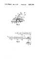
- FIG. 4shows part of a vehicle-mounted laser beam scanning head
- FIG. 5shows circuits associated therewith.
- FIG. 1there is shown in schematic form an area defined by a perimeter shown in broken line 1 within which two mobile trucks 2 and 3 are to be controlled and guided under the overall control of a base station 4.
- the trucks 2 and 3are utilised to transfer material between a store area 5 and a work position 6.
- the store areacan, for example, accommodate raw material which is to be machined at the work position into a required shape, or otherwise processed in accordance with a particular requirement.
- the finished work piecesare transferred by means of one of the trucks to a further holding area 7 for removal and utilisation as required.
- the base station 4allocates required destinations to each of the trucks 2 and 3 via any convenient form of communication link.
- a short range radio communications linkcan be provided, or, alternatively, an optical communication system utilising infra-red transmitters and detectors mounted in the ceilings of the area defined by the perimeter 1.
- each vehiclecontains a co-operating infra-red sensor and transmitter directed upward.
- reflector boards 8located around the area of movement to achieve a high degree of positional accuracy.
- Each reflector boardcontains a unique code which indicates its identity and precise position. The reflector boards are described in greater detail subsequently with reference to FIG. 3.
- Each vehiclecontains a scanning laser beam which rotates in azimuth so that it scans across each of those reflector boards which are within its field of view.
- the reflector boardis composed of a retro-reflective material which is such that a narrow beam is reflected in the same direction from which the original illumination is incident upon it.
- the vehiclecontinuously monitors its own position as it moves along a path which takes it to its required destination. Its own position is continuously transmitted back to the base station so that the base station is aware of the location of all trucks to enable it to assume overall command to avoid a collision between two trucks. Particularly precise control is required in the region of the store area 5, the work position 6 and the holding area 7 and for this reason additional reflectors are positioned around these locations as indicated in FIG. 1.
- the store area and the holding areamay be much larger than illustrated, and of complex configurations. For example, each may consist of a large number of bays divided into separate sections by means of alley-ways down which the trucks can navigate. In this case additional reflector boards are required so as to ensure a truck is always able to communicate with at least two of them whilst in any position.
- a truckis illustrated diagramatically in FIG. 2, and it will be seen that it comprises a small vehicle having a load carrying surface 10 and a raised portion 11 at one end which supports a rotating scanner head 12.
- a scanner headrotates in azimuth a very narrow fan-shaped laser beam 14 is transmitted, although it may be desired to use just a narrow horizontal pencil-like beam.
- the fan beamhas an appreciable vertical spread which is determined by the apex angle of the fan so as to ensure that at least a portion of the laser beam 14 is incident upon a reflector board 8 regardless of significant variations in the height of the reflector board above ground level. It will be seen that the reflector board 8 contains an array of the vertically disposed stripes referred to previously.
- the reflector board 8therefore returns an amplitude modulated beam of light having a pattern which varies in time which corresponds to the bright (reflective) and dark (absorbing) portions of the reflector board.
- the returned signalis received by a detector located within the scanning head, and from this information the vehicle can determine its precise bearing relative to that of the reflector board 8 and by utilising returns from two or more boards it can make minor corrections to its path to compensate for any positional errors.
- a reflector boardis illustrated in greater detail in FIG. 3. It will be seen that it contains reflective stripes, which are indicated by cross-hatching, which are spaced apart by dark stripes, i.e. non-reflective regions. The width of the reflective stripes and the associated non-reflective stripes together determine the nature of the coded signal which is obtained. Thus in FIG. 3 a digital "1" is represented by a relatively wide reflective stripe followed by a narrower non-reflective stripe, and a digital "0" is represented by the inverse combination of these stripes.
- the reflector board 8is scanned from left to right in this example, the first few stripes serve to indicate unambiguously that a reflector board has been found. It is important to distinguish a reflector board from other reflective bodies within the field of view which could produce a confusingly similar reflector pattern, such as a metal grid or mesh having a number of vertically disposed wires. Once the initial pattern of 1's and 0's has been found which identify a reflector board, a unique code follows, identifying that particular reflector board so as to distinguish it from all other reflector boards which are mounted within the area.
- the final vertical stripe in this exampleis a position stripe which indicates the position of the end of the reflector board with a very high degree of accuracy, typically to within one cm, although any predetermined stripe could be designated as the position member.
- a stripecould have an appreciable width, in a system requiring very high positional accuracy, the boundary edge of the stripe will be used to define the position of the reflector board.
- the angular bearing of the vehiclecan be determined relative to that of the reflector board at the instant that the rotating scanning head receives a reflected signal from the end stripe.
- two reflector boardscan be associated with a particular reflector position such that each can be easily seen by trucks approaching in either direction.
- the stripes at the abutting ends of the two boardsserve to define a common position relative to which the truck orientates itself.
- An accurately calibrated optical encoderkeeps track of the angular position of the rotating scanner head 12 relative to that of the vehicle.
- An angular bearing of this kind received from at least two reflector boardsenables the absolute position of the vehicle to be determined accurately.
- the angular offset of the vehicle from the reflector boardsindicate its actual headings and can be used to permit navigation of the vehicle to proceed to a required destination.
- a laser 21generates a very narrow beam of intense coherent light which is expanded by means of an optical system 23 into a parallel sided pencil-like beam of about 5 mm width.
- This lasermay be a conventional gas-filled type consisting of a mixture of helium or neon, or it may be a semi-conductor source such as a gallium arsenide laser diode.
- the narrow pencil beamis emitted by the optical system 23 and is reflected at a mirror 24 upwardly on to a further mirror 25 which is fixed relative to the vehicle.
- the beamis then reflected on to a further small mirror 26 which is carried by the centre of a plate, the remaining annular region of which constitutes a very large area light sensor 27.
- the transmitted beamis passed via a cylindrical lens 28 on to the reflecting surface of an inclined mirror 29.
- the lensin combination with the mirror produce a very wide angle fan beam defined by the lines 30 and 31.
- the fantypically has an apex angle of about 40°.
- the mirror 29has a flat planar surface and is supported by a rotating frame 32 which is secured to a base diode 33 supported by bearings 34 and 35 and which are driven by means of a small motor 36 so that the mirror 29, and hence the laser beam, are rotated in azimuth at a rate of about three revolutions per second.
- a reflector boardLight reflected by a reflector board is returned in a parallel beam, represented by the lines 38 and 39, which is incident upon the inclined mirror surface 29 and directed downwardly on to the very large area of the light sensor 27.
- the use of retroreflective stripes on the target boardsensures that a very high proportion of the incident light is returned to the sensor 27, as retroreflective material returns incident illumination back along its original path largely independently of the angle of incidence.
- the sensor 27comprises a photo diode.
- An interference filtercan be placed immediately above the sensor 27 to reduce the effect of ambient light.
- the informationis extracted in electrical form via an interface device 40 and fed to an analysing circuit for utilisation as required.
- the light outputcan conveniently be pulsed at a high predetermined frequency, typically above 1 MHz, and the use of a band pass filter tuned to the same frequency in the output path of the sensor 27 provides positive discrimination against interference by ambient light.
- a band pass filtertuned to the same frequency in the output path of the sensor 27 provides positive discrimination against interference by ambient light.
- FIG. 5An arrangement of this kind is indicated diagramatically in FIG. 5, in which an oscillator 41 running at about 100 MHz is used to drive the gallium arsenide diode laser 21 so as to amplitude modulate it.
- the output from the sensor 27is fed via the interface device 40 to a narrow band pass filter 42 tuned to the frequency of oscillator 41.
- the filtered signalis fed to a phase comparator 43 where it is compared with the output of the oscillator.
- the phase difference(or phase shift) is directly related to the distance of the truck from the reflector board, and is converted into a measure of distance at a converter 44.
Landscapes
- Physics & Mathematics (AREA)
- Engineering & Computer Science (AREA)
- Electromagnetism (AREA)
- General Physics & Mathematics (AREA)
- Radar, Positioning & Navigation (AREA)
- Remote Sensing (AREA)
- Aviation & Aerospace Engineering (AREA)
- Automation & Control Theory (AREA)
- Computer Networks & Wireless Communication (AREA)
- Optics & Photonics (AREA)
- Control Of Position, Course, Altitude, Or Attitude Of Moving Bodies (AREA)
Abstract
Description
Claims (11)
Applications Claiming Priority (2)
| Application Number | Priority Date | Filing Date | Title |
|---|---|---|---|
| GB838313339AGB8313339D0 (en) | 1983-05-14 | 1983-05-14 | Vehicle guidance |
| GB8313339 | 1983-05-14 |
Publications (1)
| Publication Number | Publication Date |
|---|---|
| US4647784Atrue US4647784A (en) | 1987-03-03 |
Family
ID=10542757
Family Applications (1)
| Application Number | Title | Priority Date | Filing Date |
|---|---|---|---|
| US06/608,242Expired - LifetimeUS4647784A (en) | 1983-05-14 | 1984-05-08 | Vehicle guidance and control system |
Country Status (2)
| Country | Link |
|---|---|
| US (1) | US4647784A (en) |
| GB (1) | GB8313339D0 (en) |
Cited By (78)
| Publication number | Priority date | Publication date | Assignee | Title |
|---|---|---|---|---|
| US4700301A (en)* | 1983-11-02 | 1987-10-13 | Dyke Howard L | Method of automatically steering agricultural type vehicles |
| US4790402A (en)* | 1987-09-28 | 1988-12-13 | Tennant Company | Automated guided vehicle |
| US4796198A (en)* | 1986-10-17 | 1989-01-03 | The United States Of America As Represented By The United States Department Of Energy | Method for laser-based two-dimensional navigation system in a structured environment |
| US4797557A (en)* | 1986-05-23 | 1989-01-10 | Aktiebolaget Electrolux | Position sensing system for a moving object wherein a lens focuses light onto a radiation sensitive matrix |
| DE3725896A1 (en)* | 1987-08-05 | 1989-02-16 | Angele Eduard Ing Grad | Method and device for detecting the position of a vehicle |
| US4846297A (en)* | 1987-09-28 | 1989-07-11 | Tennant Company | Automated guided vehicle |
| US4887223A (en)* | 1985-08-30 | 1989-12-12 | Texas Instruments Incorporated | Visual navigation system for a mobile robot having capabilities of regenerating of hidden images |
| US4906159A (en)* | 1989-03-22 | 1990-03-06 | Caterpillar Industrial Inc. | Freely positionable load carrying attachment for an automatic guided vehicle |
| WO1990002987A1 (en)* | 1988-09-09 | 1990-03-22 | Caterpillar Industrial Inc. | Vehicle guidance system |
| US4935871A (en)* | 1989-02-23 | 1990-06-19 | Caterpillar Inc. | Electronic road system generation method for an automatic guided vehicle |
| US4967064A (en)* | 1989-06-30 | 1990-10-30 | Tennant Company | Method and apparatus for a target determining apparatus having increased range |
| DE3930109C1 (en)* | 1989-09-09 | 1990-11-15 | Pepperl & Fuchs Gmbh, 6800 Mannheim, De | |
| US4973206A (en)* | 1987-06-18 | 1990-11-27 | General Signal Corporation | Method and apparatus for loading and unloading semitrailers and off railroad flat cars |
| US5008557A (en)* | 1989-03-01 | 1991-04-16 | Honda Giken Kogyo Kabushiki Kaisha | Position detector for moving vehicle |
| US5011288A (en)* | 1988-05-13 | 1991-04-30 | Honda Giken Kogyo Kabushiki Kaisha | Position control system for unmanned automated vehicle |
| US5067872A (en)* | 1987-06-18 | 1991-11-26 | Knorr Brake Holding Corporation | Method for semitrailer transfer |
| US5153833A (en)* | 1988-06-23 | 1992-10-06 | Total Spectrum Manufacturing, Inc. | Robotic television-camera dolly system |
| US5155684A (en)* | 1988-10-25 | 1992-10-13 | Tennant Company | Guiding an unmanned vehicle by reference to overhead features |
| US5202832A (en)* | 1991-01-29 | 1993-04-13 | R. R. Donnelley & Sons Co. | Material handling automation system using portable transfer module |
| US5202742A (en)* | 1990-10-03 | 1993-04-13 | Aisin Seiki Kabushiki Kaisha | Laser radar for a vehicle lateral guidance system |
| GB2264184A (en)* | 1992-01-12 | 1993-08-18 | Israel State | Large area movement robots |
| US5357432A (en)* | 1990-10-03 | 1994-10-18 | Aisin Seiki Kabushiki Kaisha | Automatic lateral guidance control system |
| US5367458A (en)* | 1993-08-10 | 1994-11-22 | Caterpillar Industrial Inc. | Apparatus and method for identifying scanned reflective anonymous targets |
| US5375059A (en)* | 1990-02-05 | 1994-12-20 | Caterpillar Inc. | Vehicle position determination system and method |
| US5390118A (en)* | 1990-10-03 | 1995-02-14 | Aisin Seiki Kabushiki Kaisha | Automatic lateral guidance control system |
| US5483455A (en)* | 1992-09-08 | 1996-01-09 | Caterpillar Inc. | Method and apparatus for determining the location of a vehicle |
| US5555503A (en)* | 1989-12-11 | 1996-09-10 | Caterpillar Inc. | System and method for providing accurate vehicle positioning using spatial bias techniques |
| WO1997039394A1 (en)* | 1996-04-15 | 1997-10-23 | Apogeum Ab | A method for determining the positions of a plurality of anonymous fixed reference objects for mobile surface transportation and a device for determining said positions |
| US5739785A (en)* | 1993-03-04 | 1998-04-14 | Trimble Navigation Limited | Location and generation of high accuracy survey control marks using satellites |
| US5805286A (en)* | 1995-11-07 | 1998-09-08 | Fraunhofer-Gesellschaft Zur Forderung Der Angewandten Forschung E.V. | Process for determination of the position of a vehicle in a plane of travel |
| US5821718A (en)* | 1996-05-07 | 1998-10-13 | Chrysler Corporation | Robotic system for automated durability road (ADR) facility |
| US5867089A (en)* | 1996-09-03 | 1999-02-02 | Chrysler Corporation | Base-to-remotely controlled vehicle communications for automated durability road (ADR) facility |
| US5906647A (en)* | 1996-09-03 | 1999-05-25 | Chrysler Corporation | Vehicle mounted guidance antenna for automated durability road (ADR) facility |
| US5908454A (en)* | 1996-09-03 | 1999-06-01 | Chrysler Corporation | Operator interface for automated durability road (ADR) facility |
| US5938705A (en)* | 1996-09-03 | 1999-08-17 | Chrysler Corporation | Vehicle controller (VCON) for automated durability road (ADR) facility |
| US5991674A (en)* | 1996-05-02 | 1999-11-23 | Chrysler Corporation | Floor shifter linkage for robotic control of vehicle |
| US5999866A (en)* | 1996-11-05 | 1999-12-07 | Carnegie Mellon University | Infrastructure independent position determining system |
| US6061613A (en)* | 1996-09-03 | 2000-05-09 | Chrysler Corporation | Base station for automated durability road (ADR) facility |
| US6141620A (en)* | 1996-09-03 | 2000-10-31 | Chrysler Corporation | Vehicle control system for automated durability road (ADR) facility |
| US6374155B1 (en) | 1999-11-24 | 2002-04-16 | Personal Robotics, Inc. | Autonomous multi-platform robot system |
| WO2002091095A1 (en)* | 2001-05-10 | 2002-11-14 | Ibeo Automobile Sensor Gmbh | Calibrating method |
| US6603865B1 (en)* | 2000-01-27 | 2003-08-05 | President Of Nagoya University | System for optically performing position detection and data communication |
| US6741054B2 (en) | 2000-05-02 | 2004-05-25 | Vision Robotics Corporation | Autonomous floor mopping apparatus |
| US6807478B2 (en)* | 2001-12-27 | 2004-10-19 | Koninklijke Philips Electronics N.V. | In-building navigation system |
| US20040267442A1 (en)* | 2002-07-02 | 2004-12-30 | Linda Fehr | Computer-controlled power wheelchair navigation system |
| US6857493B2 (en) | 2002-02-13 | 2005-02-22 | Paragon Technologies, Inc. | Automatic load positioning for a conveyor cart |
| US20050065655A1 (en)* | 2003-09-16 | 2005-03-24 | Samsung Electronics Co., Ltd. | Apparatus and method for estimating a position and an orientation of a mobile robot |
| US7077619B2 (en)* | 2001-07-13 | 2006-07-18 | 3M Innovative Properties Company | Continuous motion robotic manipulator |
| US20070271002A1 (en)* | 2006-05-22 | 2007-11-22 | Hoskinson Reed L | Systems and methods for the autonomous control, automated guidance, and global coordination of moving process machinery |
| US20080219508A1 (en)* | 2007-03-08 | 2008-09-11 | Honeywell International Inc. | Vision based navigation and guidance system |
| US20080228384A1 (en)* | 2007-03-17 | 2008-09-18 | Erickson Clinton W | Navigational system for a personal mobility device |
| US20080300777A1 (en)* | 2002-07-02 | 2008-12-04 | Linda Fehr | Computer-controlled power wheelchair navigation system |
| EP2006708A1 (en)* | 2007-06-15 | 2008-12-24 | Robert Bosch GmbH | Localising system for a robotic vehicle |
| US20110010023A1 (en)* | 2005-12-03 | 2011-01-13 | Kunzig Robert S | Method and apparatus for managing and controlling manned and automated utility vehicles |
| US20110097014A1 (en)* | 2009-10-26 | 2011-04-28 | Industrial Technology Research Institute | Self-positioning device and method thereof |
| US20110153072A1 (en)* | 2009-12-17 | 2011-06-23 | Noel Wayne Anderson | Enhanced visual landmark for localization |
| US20110153136A1 (en)* | 2009-12-17 | 2011-06-23 | Noel Wayne Anderson | System and method for area coverage using sector decomposition |
| US20110153338A1 (en)* | 2009-12-17 | 2011-06-23 | Noel Wayne Anderson | System and method for deploying portable landmarks |
| US8364136B2 (en) | 1999-02-01 | 2013-01-29 | Steven M Hoffberg | Mobile system, a method of operating mobile system and a non-transitory computer readable medium for a programmable control of a mobile system |
| US8369967B2 (en) | 1999-02-01 | 2013-02-05 | Hoffberg Steven M | Alarm system controller and a method for controlling an alarm system |
| US8892495B2 (en) | 1991-12-23 | 2014-11-18 | Blanding Hovenweep, Llc | Adaptive pattern recognition based controller apparatus and method and human-interface therefore |
| US9151633B2 (en) | 1998-01-27 | 2015-10-06 | Steven M. Hoffberg | Mobile communication device for delivering targeted advertisements |
| US20160026185A1 (en)* | 2013-03-15 | 2016-01-28 | Mtd Products Inc | Autonomous mobile work system comprising a variable reflectivity base station |
| US20160313740A1 (en)* | 2014-01-14 | 2016-10-27 | Grenzebach Maschinenbau Gmbh | Orientation device for electrically operated transportation vehicles, automatically guided in factory building |
| US10299431B2 (en) | 2014-09-05 | 2019-05-28 | Mtd Products Inc | Quick change lawn mower blades |
| US10361802B1 (en) | 1999-02-01 | 2019-07-23 | Blanding Hovenweep, Llc | Adaptive pattern recognition based control system and method |
| WO2020088782A1 (en)* | 2018-11-02 | 2020-05-07 | Moba Mobile Automation Ag | Sensor system for a road paver |
| EP3654061A1 (en)* | 2018-11-16 | 2020-05-20 | Swareflex GmbH | System and method for position measurement |
| US20200166954A1 (en)* | 2017-10-04 | 2020-05-28 | Arche Information Inc. | Comprehensive multi-agent robotics management system |
| WO2020125951A1 (en)* | 2018-12-18 | 2020-06-25 | Volvo Truck Corporation | A method for determining coordinates of a vehicle |
| CN112240205A (en)* | 2019-07-18 | 2021-01-19 | 联邦科学和工业研究组织 | Machine guidance integration |
| US10943273B2 (en) | 2003-02-05 | 2021-03-09 | The Hoffberg Family Trust 2004-1 | System and method for determining contingent relevance |
| US20210124055A1 (en)* | 2019-10-24 | 2021-04-29 | Nuro, Inc. | Single beam digitally modulated lidar for autonomous vehicle distance sensing |
| US11307307B2 (en)* | 2017-12-22 | 2022-04-19 | Guangdong Jaten Robot & Automation Co., Ltd. | Reflector matching algorithm based on triangle perimeter matching |
| US20230113535A1 (en)* | 2021-10-13 | 2023-04-13 | U.S. Army DEVCOM, Army Research Laboratory | Optical positioning system |
| JP7708943B1 (en)* | 2024-08-08 | 2025-07-15 | 大豊建設株式会社 | Coordinate unified measurement system and coordinate unified measurement method |
| US12385231B2 (en) | 2020-01-31 | 2025-08-12 | Moba Mobile Automation Ag | Measuring system and controller |
| US12435477B2 (en) | 2021-03-23 | 2025-10-07 | Moba Mobile Automation Ag | Measuring system |
Citations (4)
| Publication number | Priority date | Publication date | Assignee | Title |
|---|---|---|---|---|
| US4307791A (en)* | 1978-12-06 | 1981-12-29 | Bell & Howell Company | Line follower vehicle with scanning head |
| US4328422A (en)* | 1978-03-27 | 1982-05-04 | Litton Systems, Inc. | Automated warehouse vehicle position determining system |
| US4482960A (en)* | 1981-11-20 | 1984-11-13 | Diffracto Ltd. | Robot tractors |
| US4531061A (en)* | 1982-07-01 | 1985-07-23 | Jacob Rabinow | Electrically settable escort memory |
- 1983
- 1983-05-14GBGB838313339Apatent/GB8313339D0/enactivePending
- 1984
- 1984-05-08USUS06/608,242patent/US4647784A/ennot_activeExpired - Lifetime
Patent Citations (4)
| Publication number | Priority date | Publication date | Assignee | Title |
|---|---|---|---|---|
| US4328422A (en)* | 1978-03-27 | 1982-05-04 | Litton Systems, Inc. | Automated warehouse vehicle position determining system |
| US4307791A (en)* | 1978-12-06 | 1981-12-29 | Bell & Howell Company | Line follower vehicle with scanning head |
| US4482960A (en)* | 1981-11-20 | 1984-11-13 | Diffracto Ltd. | Robot tractors |
| US4531061A (en)* | 1982-07-01 | 1985-07-23 | Jacob Rabinow | Electrically settable escort memory |
Cited By (114)
| Publication number | Priority date | Publication date | Assignee | Title |
|---|---|---|---|---|
| US4700301A (en)* | 1983-11-02 | 1987-10-13 | Dyke Howard L | Method of automatically steering agricultural type vehicles |
| US4887223A (en)* | 1985-08-30 | 1989-12-12 | Texas Instruments Incorporated | Visual navigation system for a mobile robot having capabilities of regenerating of hidden images |
| US4797557A (en)* | 1986-05-23 | 1989-01-10 | Aktiebolaget Electrolux | Position sensing system for a moving object wherein a lens focuses light onto a radiation sensitive matrix |
| US4796198A (en)* | 1986-10-17 | 1989-01-03 | The United States Of America As Represented By The United States Department Of Energy | Method for laser-based two-dimensional navigation system in a structured environment |
| US4973206A (en)* | 1987-06-18 | 1990-11-27 | General Signal Corporation | Method and apparatus for loading and unloading semitrailers and off railroad flat cars |
| US5067872A (en)* | 1987-06-18 | 1991-11-26 | Knorr Brake Holding Corporation | Method for semitrailer transfer |
| DE3725896A1 (en)* | 1987-08-05 | 1989-02-16 | Angele Eduard Ing Grad | Method and device for detecting the position of a vehicle |
| DE3725896C2 (en)* | 1987-08-05 | 2001-03-08 | Frank Sinn | Method and device for determining the position of a vehicle |
| US4790402A (en)* | 1987-09-28 | 1988-12-13 | Tennant Company | Automated guided vehicle |
| US4846297A (en)* | 1987-09-28 | 1989-07-11 | Tennant Company | Automated guided vehicle |
| US5011288A (en)* | 1988-05-13 | 1991-04-30 | Honda Giken Kogyo Kabushiki Kaisha | Position control system for unmanned automated vehicle |
| US5153833A (en)* | 1988-06-23 | 1992-10-06 | Total Spectrum Manufacturing, Inc. | Robotic television-camera dolly system |
| WO1990002987A1 (en)* | 1988-09-09 | 1990-03-22 | Caterpillar Industrial Inc. | Vehicle guidance system |
| US4918607A (en)* | 1988-09-09 | 1990-04-17 | Caterpillar Industrial Inc. | Vehicle guidance system |
| US5155684A (en)* | 1988-10-25 | 1992-10-13 | Tennant Company | Guiding an unmanned vehicle by reference to overhead features |
| US4935871A (en)* | 1989-02-23 | 1990-06-19 | Caterpillar Inc. | Electronic road system generation method for an automatic guided vehicle |
| US5008557A (en)* | 1989-03-01 | 1991-04-16 | Honda Giken Kogyo Kabushiki Kaisha | Position detector for moving vehicle |
| US4906159A (en)* | 1989-03-22 | 1990-03-06 | Caterpillar Industrial Inc. | Freely positionable load carrying attachment for an automatic guided vehicle |
| US4967064A (en)* | 1989-06-30 | 1990-10-30 | Tennant Company | Method and apparatus for a target determining apparatus having increased range |
| DE3930109C1 (en)* | 1989-09-09 | 1990-11-15 | Pepperl & Fuchs Gmbh, 6800 Mannheim, De | |
| US5610815A (en)* | 1989-12-11 | 1997-03-11 | Caterpillar Inc. | Integrated vehicle positioning and navigation system, apparatus and method |
| US5555503A (en)* | 1989-12-11 | 1996-09-10 | Caterpillar Inc. | System and method for providing accurate vehicle positioning using spatial bias techniques |
| US5375059A (en)* | 1990-02-05 | 1994-12-20 | Caterpillar Inc. | Vehicle position determination system and method |
| US5390125A (en)* | 1990-02-05 | 1995-02-14 | Caterpillar Inc. | Vehicle position determination system and method |
| US5357432A (en)* | 1990-10-03 | 1994-10-18 | Aisin Seiki Kabushiki Kaisha | Automatic lateral guidance control system |
| US5390118A (en)* | 1990-10-03 | 1995-02-14 | Aisin Seiki Kabushiki Kaisha | Automatic lateral guidance control system |
| US5202742A (en)* | 1990-10-03 | 1993-04-13 | Aisin Seiki Kabushiki Kaisha | Laser radar for a vehicle lateral guidance system |
| US5202832A (en)* | 1991-01-29 | 1993-04-13 | R. R. Donnelley & Sons Co. | Material handling automation system using portable transfer module |
| US8892495B2 (en) | 1991-12-23 | 2014-11-18 | Blanding Hovenweep, Llc | Adaptive pattern recognition based controller apparatus and method and human-interface therefore |
| GB2264184B (en)* | 1992-01-12 | 1996-01-17 | Israel State | Large area movement robots |
| US5467273A (en)* | 1992-01-12 | 1995-11-14 | State Of Israel, Ministry Of Defence, Rafael Armament Development Authority | Large area movement robot |
| GB2264184A (en)* | 1992-01-12 | 1993-08-18 | Israel State | Large area movement robots |
| US5483455A (en)* | 1992-09-08 | 1996-01-09 | Caterpillar Inc. | Method and apparatus for determining the location of a vehicle |
| US5739785A (en)* | 1993-03-04 | 1998-04-14 | Trimble Navigation Limited | Location and generation of high accuracy survey control marks using satellites |
| US5367458A (en)* | 1993-08-10 | 1994-11-22 | Caterpillar Industrial Inc. | Apparatus and method for identifying scanned reflective anonymous targets |
| US5805286A (en)* | 1995-11-07 | 1998-09-08 | Fraunhofer-Gesellschaft Zur Forderung Der Angewandten Forschung E.V. | Process for determination of the position of a vehicle in a plane of travel |
| DE19541379C2 (en)* | 1995-11-07 | 2001-01-18 | Fraunhofer Ges Forschung | Method for determining the position of a vehicle in a driving plane |
| WO1997039394A1 (en)* | 1996-04-15 | 1997-10-23 | Apogeum Ab | A method for determining the positions of a plurality of anonymous fixed reference objects for mobile surface transportation and a device for determining said positions |
| US6012003A (en)* | 1996-04-15 | 2000-01-04 | Apogeum Ab | Method for determining the positions of a plurality of anonymous fixed reference objects for mobile surface transportation and a device for determining said positions |
| US5991674A (en)* | 1996-05-02 | 1999-11-23 | Chrysler Corporation | Floor shifter linkage for robotic control of vehicle |
| US5821718A (en)* | 1996-05-07 | 1998-10-13 | Chrysler Corporation | Robotic system for automated durability road (ADR) facility |
| US5906647A (en)* | 1996-09-03 | 1999-05-25 | Chrysler Corporation | Vehicle mounted guidance antenna for automated durability road (ADR) facility |
| US5938705A (en)* | 1996-09-03 | 1999-08-17 | Chrysler Corporation | Vehicle controller (VCON) for automated durability road (ADR) facility |
| US6061613A (en)* | 1996-09-03 | 2000-05-09 | Chrysler Corporation | Base station for automated durability road (ADR) facility |
| US6141620A (en)* | 1996-09-03 | 2000-10-31 | Chrysler Corporation | Vehicle control system for automated durability road (ADR) facility |
| US5908454A (en)* | 1996-09-03 | 1999-06-01 | Chrysler Corporation | Operator interface for automated durability road (ADR) facility |
| US5867089A (en)* | 1996-09-03 | 1999-02-02 | Chrysler Corporation | Base-to-remotely controlled vehicle communications for automated durability road (ADR) facility |
| US5999866A (en)* | 1996-11-05 | 1999-12-07 | Carnegie Mellon University | Infrastructure independent position determining system |
| US6453223B1 (en) | 1996-11-05 | 2002-09-17 | Carnegie Mellon University | Infrastructure independent position determining system |
| US9151633B2 (en) | 1998-01-27 | 2015-10-06 | Steven M. Hoffberg | Mobile communication device for delivering targeted advertisements |
| US9551582B2 (en) | 1998-01-27 | 2017-01-24 | Blanding Hovenweep, Llc | Mobile communication device |
| US10127816B2 (en) | 1998-01-27 | 2018-11-13 | Blanding Hovenweep, Llc | Detection and alert of automobile braking event |
| US10361802B1 (en) | 1999-02-01 | 2019-07-23 | Blanding Hovenweep, Llc | Adaptive pattern recognition based control system and method |
| US9535563B2 (en) | 1999-02-01 | 2017-01-03 | Blanding Hovenweep, Llc | Internet appliance system and method |
| US8364136B2 (en) | 1999-02-01 | 2013-01-29 | Steven M Hoffberg | Mobile system, a method of operating mobile system and a non-transitory computer readable medium for a programmable control of a mobile system |
| US8369967B2 (en) | 1999-02-01 | 2013-02-05 | Hoffberg Steven M | Alarm system controller and a method for controlling an alarm system |
| EP1240562B1 (en)* | 1999-11-24 | 2004-06-16 | Vision Robotics Corporation | Autonomous multi-platform robot system |
| US6374155B1 (en) | 1999-11-24 | 2002-04-16 | Personal Robotics, Inc. | Autonomous multi-platform robot system |
| US6496755B2 (en) | 1999-11-24 | 2002-12-17 | Personal Robotics, Inc. | Autonomous multi-platform robot system |
| US6603865B1 (en)* | 2000-01-27 | 2003-08-05 | President Of Nagoya University | System for optically performing position detection and data communication |
| US6741054B2 (en) | 2000-05-02 | 2004-05-25 | Vision Robotics Corporation | Autonomous floor mopping apparatus |
| WO2002091095A1 (en)* | 2001-05-10 | 2002-11-14 | Ibeo Automobile Sensor Gmbh | Calibrating method |
| US7077619B2 (en)* | 2001-07-13 | 2006-07-18 | 3M Innovative Properties Company | Continuous motion robotic manipulator |
| US6807478B2 (en)* | 2001-12-27 | 2004-10-19 | Koninklijke Philips Electronics N.V. | In-building navigation system |
| US6857493B2 (en) | 2002-02-13 | 2005-02-22 | Paragon Technologies, Inc. | Automatic load positioning for a conveyor cart |
| US20040267442A1 (en)* | 2002-07-02 | 2004-12-30 | Linda Fehr | Computer-controlled power wheelchair navigation system |
| US20080300777A1 (en)* | 2002-07-02 | 2008-12-04 | Linda Fehr | Computer-controlled power wheelchair navigation system |
| US7383107B2 (en) | 2002-07-02 | 2008-06-03 | The United States Of America As Represented By The Department Of Veterans Affairs | Computer-controlled power wheelchair navigation system |
| US6842692B2 (en) | 2002-07-02 | 2005-01-11 | The United States Of America As Represented By The Department Of Veterans Affairs | Computer-controlled power wheelchair navigation system |
| US10943273B2 (en) | 2003-02-05 | 2021-03-09 | The Hoffberg Family Trust 2004-1 | System and method for determining contingent relevance |
| US11790413B2 (en) | 2003-02-05 | 2023-10-17 | Hoffberg Family Trust 2 | System and method for communication |
| US7765027B2 (en)* | 2003-09-16 | 2010-07-27 | Samsung Electronics Co., Ltd. | Apparatus and method for estimating a position and an orientation of a mobile robot |
| CN1598610B (en)* | 2003-09-16 | 2010-10-27 | 三星电子株式会社 | Apparatus and method for estimating the position and orientation of a mobile robot |
| US20050065655A1 (en)* | 2003-09-16 | 2005-03-24 | Samsung Electronics Co., Ltd. | Apparatus and method for estimating a position and an orientation of a mobile robot |
| EP1517210A3 (en)* | 2003-09-16 | 2006-10-04 | Samsung Electronics Co., Ltd. | Apparatus and method for estimating position and orientation of mobile robot |
| US8381982B2 (en) | 2005-12-03 | 2013-02-26 | Sky-Trax, Inc. | Method and apparatus for managing and controlling manned and automated utility vehicles |
| US20110010023A1 (en)* | 2005-12-03 | 2011-01-13 | Kunzig Robert S | Method and apparatus for managing and controlling manned and automated utility vehicles |
| US20070271002A1 (en)* | 2006-05-22 | 2007-11-22 | Hoskinson Reed L | Systems and methods for the autonomous control, automated guidance, and global coordination of moving process machinery |
| US7881497B2 (en) | 2007-03-08 | 2011-02-01 | Honeywell International Inc. | Vision based navigation and guidance system |
| US20080219508A1 (en)* | 2007-03-08 | 2008-09-11 | Honeywell International Inc. | Vision based navigation and guidance system |
| US20080228384A1 (en)* | 2007-03-17 | 2008-09-18 | Erickson Clinton W | Navigational system for a personal mobility device |
| EP2006708A1 (en)* | 2007-06-15 | 2008-12-24 | Robert Bosch GmbH | Localising system for a robotic vehicle |
| US8385683B2 (en) | 2009-10-26 | 2013-02-26 | Industrial Technology Research Institute | Self-positioning device and method thereof |
| US20110097014A1 (en)* | 2009-10-26 | 2011-04-28 | Industrial Technology Research Institute | Self-positioning device and method thereof |
| US8635015B2 (en)* | 2009-12-17 | 2014-01-21 | Deere & Company | Enhanced visual landmark for localization |
| US20110153072A1 (en)* | 2009-12-17 | 2011-06-23 | Noel Wayne Anderson | Enhanced visual landmark for localization |
| US20110153136A1 (en)* | 2009-12-17 | 2011-06-23 | Noel Wayne Anderson | System and method for area coverage using sector decomposition |
| US8989946B2 (en) | 2009-12-17 | 2015-03-24 | Deere & Company | System and method for area coverage using sector decomposition |
| US8666554B2 (en) | 2009-12-17 | 2014-03-04 | Deere & Company | System and method for area coverage using sector decomposition |
| US8224516B2 (en) | 2009-12-17 | 2012-07-17 | Deere & Company | System and method for area coverage using sector decomposition |
| US20110153338A1 (en)* | 2009-12-17 | 2011-06-23 | Noel Wayne Anderson | System and method for deploying portable landmarks |
| US20160026185A1 (en)* | 2013-03-15 | 2016-01-28 | Mtd Products Inc | Autonomous mobile work system comprising a variable reflectivity base station |
| US9829891B2 (en)* | 2013-03-15 | 2017-11-28 | Mtd Products Inc | Autonomous mobile work system comprising a variable reflectivity base station |
| US9971351B2 (en)* | 2014-01-14 | 2018-05-15 | Grenzebach Maschinenbau Gmbh | Orientation device for electrically operated transportation vehicles, automatically guided in factory building |
| US20160313740A1 (en)* | 2014-01-14 | 2016-10-27 | Grenzebach Maschinenbau Gmbh | Orientation device for electrically operated transportation vehicles, automatically guided in factory building |
| US10299431B2 (en) | 2014-09-05 | 2019-05-28 | Mtd Products Inc | Quick change lawn mower blades |
| US20200166954A1 (en)* | 2017-10-04 | 2020-05-28 | Arche Information Inc. | Comprehensive multi-agent robotics management system |
| US11307307B2 (en)* | 2017-12-22 | 2022-04-19 | Guangdong Jaten Robot & Automation Co., Ltd. | Reflector matching algorithm based on triangle perimeter matching |
| US11885881B2 (en) | 2018-11-02 | 2024-01-30 | Moba Mobile Automation Ag | Sensor system for a road finishing machine |
| CN113260876A (en)* | 2018-11-02 | 2021-08-13 | 摩巴自动控制股份有限公司 | Sensor system for a road finishing machine |
| WO2020088782A1 (en)* | 2018-11-02 | 2020-05-07 | Moba Mobile Automation Ag | Sensor system for a road paver |
| EP3654061A1 (en)* | 2018-11-16 | 2020-05-20 | Swareflex GmbH | System and method for position measurement |
| WO2020099637A1 (en)* | 2018-11-16 | 2020-05-22 | Swareflex Gmbh | System and method for position determination |
| WO2020125951A1 (en)* | 2018-12-18 | 2020-06-25 | Volvo Truck Corporation | A method for determining coordinates of a vehicle |
| US12422554B2 (en) | 2018-12-18 | 2025-09-23 | Volvo Truck Corporation | Method for determining coordinates of a vehicle |
| US11506053B2 (en)* | 2019-07-18 | 2022-11-22 | Commonwealth Scientific And Industrial Research Organisation | Machine guidance integration |
| AU2020202698B2 (en)* | 2019-07-18 | 2025-02-27 | Commonwealth Scientific And Industrial Research Organisation | Machine Guidance Integration |
| CN112240205A (en)* | 2019-07-18 | 2021-01-19 | 联邦科学和工业研究组织 | Machine guidance integration |
| US20210124055A1 (en)* | 2019-10-24 | 2021-04-29 | Nuro, Inc. | Single beam digitally modulated lidar for autonomous vehicle distance sensing |
| US11899116B2 (en)* | 2019-10-24 | 2024-02-13 | Nuro, Inc. | Single beam digitally modulated lidar for autonomous vehicle distance sensing |
| US12385231B2 (en) | 2020-01-31 | 2025-08-12 | Moba Mobile Automation Ag | Measuring system and controller |
| US12435477B2 (en) | 2021-03-23 | 2025-10-07 | Moba Mobile Automation Ag | Measuring system |
| US20230113535A1 (en)* | 2021-10-13 | 2023-04-13 | U.S. Army DEVCOM, Army Research Laboratory | Optical positioning system |
| JP7708943B1 (en)* | 2024-08-08 | 2025-07-15 | 大豊建設株式会社 | Coordinate unified measurement system and coordinate unified measurement method |
Also Published As
| Publication number | Publication date |
|---|---|
| GB8313339D0 (en) | 1983-06-22 |
Similar Documents
| Publication | Publication Date | Title |
|---|---|---|
| US4647784A (en) | Vehicle guidance and control system | |
| EP0185816A1 (en) | A vehicle guidance and control system | |
| GB2143395A (en) | Vehicle guidance and control system | |
| JP2741403B2 (en) | Automatic vehicle control method | |
| AU755485B2 (en) | Method for determining the position of an automated guided vehicle | |
| JP3039801B2 (en) | Position measurement device | |
| JPH06230135A (en) | Method and apparatus for detecting obstacle | |
| KR970017041A (en) | Scanning Optical Rangefinder | |
| EP0007790A1 (en) | Driverless vehicle carrying non-directional detectors auto-guided by light signals | |
| JPH09250927A (en) | Surveying system | |
| WO1987001814A1 (en) | Method of navigating an automated guided vehicle | |
| WO1999026214A1 (en) | Device and method for detection of aircraft wire hazard | |
| EP0363072A1 (en) | Automated vehicle control | |
| CA1238706A (en) | Vehicle guidance and control system | |
| IE850052L (en) | Vehicle guidance and control system | |
| KR920009051B1 (en) | Vehicle guide | |
| US20230258804A1 (en) | Detection and communication system, control apparatus, and detection system | |
| GB1416364A (en) | Generation of scanning radio beans | |
| JPS61169908A (en) | Vehicle guidance control system | |
| JP7614022B2 (en) | Obstacle detection method and obstacle detection system | |
| JPS5870181A (en) | Radar system | |
| JPH11230746A (en) | Mobile object position detection equipment | |
| SU709013A3 (en) | Receiving device of an aircraft navigation system over signal tower radiosignals | |
| EP0559849A1 (en) | Vehicle navigation system | |
| JPH0363084B2 (en) |
Legal Events
| Date | Code | Title | Description |
|---|---|---|---|
| AS | Assignment | Owner name:GENERAL ELECTRIC COMPANY P.L.C., THE, ENGLAND Free format text:ASSIGNMENT OF ASSIGNORS INTEREST.;ASSIGNOR:STEPHENS, PHILIP E.;REEL/FRAME:004306/0689 Effective date:19840802 | |
| STCF | Information on status: patent grant | Free format text:PATENTED CASE | |
| FPAY | Fee payment | Year of fee payment:4 | |
| AS | Assignment | Owner name:GEC ELECTRIC PROJECTS LIMITED, UNITED KINGDOM Free format text:ASSIGNMENT OF ASSIGNORS INTEREST.;ASSIGNOR:GENERAL ELECTRIC COMPANY, P.L.C., THE;REEL/FRAME:006264/0841 Effective date:19890627 | |
| AS | Assignment | Owner name:GEC CONTROLS LIMITED Free format text:CHANGE OF NAME;ASSIGNOR:GEC ELECTRICAL PROJECTS LIMITED;REEL/FRAME:006270/0875 Effective date:19891220 | |
| AS | Assignment | Owner name:CEGELEC CONTROLS LTD. Free format text:CHANGE OF NAME;ASSIGNOR:GEC CONTROLS LIMITED;REEL/FRAME:006276/0394 Effective date:19910301 | |
| FEPP | Fee payment procedure | Free format text:PAYOR NUMBER ASSIGNED (ORIGINAL EVENT CODE: ASPN); ENTITY STATUS OF PATENT OWNER: LARGE ENTITY | |
| FPAY | Fee payment | Year of fee payment:8 | |
| FPAY | Fee payment | Year of fee payment:12 | |
| SULP | Surcharge for late payment | ||
| REMI | Maintenance fee reminder mailed |