US4646737A - Localized heat applying medical device - Google Patents
Localized heat applying medical deviceDownload PDFInfo
- Publication number
- US4646737A US4646737AUS06/503,783US50378383AUS4646737AUS 4646737 AUS4646737 AUS 4646737AUS 50378383 AUS50378383 AUS 50378383AUS 4646737 AUS4646737 AUS 4646737A
- Authority
- US
- United States
- Prior art keywords
- medical device
- tube
- fiber
- heat generating
- generating element
- Prior art date
- Legal status (The legal status is an assumption and is not a legal conclusion. Google has not performed a legal analysis and makes no representation as to the accuracy of the status listed.)
- Expired - Fee Related
Links
- 239000012530fluidSubstances0.000claimsabstractdescription20
- 239000000835fiberSubstances0.000claimsdescription58
- 239000000463materialSubstances0.000claimsdescription26
- 238000000034methodMethods0.000claimsdescription23
- 239000007788liquidSubstances0.000claimsdescription18
- CURLTUGMZLYLDI-UHFFFAOYSA-NCarbon dioxideChemical compoundO=C=OCURLTUGMZLYLDI-UHFFFAOYSA-N0.000claimsdescription14
- 230000017531blood circulationEffects0.000claimsdescription9
- 238000012546transferMethods0.000claimsdescription9
- 238000004891communicationMethods0.000claimsdescription8
- 230000002093peripheral effectEffects0.000claimsdescription8
- 230000005540biological transmissionEffects0.000claimsdescription7
- 239000001569carbon dioxideSubstances0.000claimsdescription7
- 229910002092carbon dioxideInorganic materials0.000claimsdescription7
- 239000002184metalSubstances0.000claimsdescription7
- -1poly(tetrafluoroethylene)Polymers0.000claimsdescription7
- 229920001343polytetrafluoroethylenePolymers0.000claimsdescription6
- 239000011248coating agentSubstances0.000claimsdescription5
- 238000000576coating methodMethods0.000claimsdescription5
- 238000003780insertionMethods0.000claimsdescription2
- 230000037431insertionEffects0.000claimsdescription2
- 241000217377Amblema plicataSpecies0.000claims1
- VRDIULHPQTYCLN-UHFFFAOYSA-NProthionamideChemical groupCCCC1=CC(C(N)=S)=CC=N1VRDIULHPQTYCLN-UHFFFAOYSA-N0.000claims1
- 210000004204blood vesselAnatomy0.000description28
- 210000001519tissueAnatomy0.000description26
- XKRFYHLGVUSROY-UHFFFAOYSA-NArgonChemical compound[Ar]XKRFYHLGVUSROY-UHFFFAOYSA-N0.000description16
- 210000001367arteryAnatomy0.000description15
- 239000008280bloodSubstances0.000description15
- 210000004369bloodAnatomy0.000description15
- 238000012360testing methodMethods0.000description13
- 230000000740bleeding effectEffects0.000description10
- 238000010438heat treatmentMethods0.000description10
- 238000005259measurementMethods0.000description9
- 229910052786argonInorganic materials0.000description8
- 238000005253claddingMethods0.000description6
- 239000000523sampleSubstances0.000description5
- VYPSYNLAJGMNEJ-UHFFFAOYSA-Nsilicon dioxideInorganic materialsO=[Si]=OVYPSYNLAJGMNEJ-UHFFFAOYSA-N0.000description5
- XLYOFNOQVPJJNP-UHFFFAOYSA-NwaterSubstancesOXLYOFNOQVPJJNP-UHFFFAOYSA-N0.000description5
- 210000001715carotid arteryAnatomy0.000description4
- 239000007789gasSubstances0.000description4
- 230000000717retained effectEffects0.000description4
- 239000000853adhesiveSubstances0.000description3
- 230000001070adhesive effectEffects0.000description3
- 210000001105femoral arteryAnatomy0.000description3
- 238000011010flushing procedureMethods0.000description3
- 239000013307optical fiberSubstances0.000description3
- 239000010453quartzSubstances0.000description3
- 230000005855radiationEffects0.000description3
- 229920005989resinPolymers0.000description3
- 239000011347resinSubstances0.000description3
- 208000024172Cardiovascular diseaseDiseases0.000description2
- KCXVZYZYPLLWCC-UHFFFAOYSA-NEDTAChemical compoundOC(=O)CN(CC(O)=O)CCN(CC(O)=O)CC(O)=OKCXVZYZYPLLWCC-UHFFFAOYSA-N0.000description2
- FAPWRFPIFSIZLT-UHFFFAOYSA-MSodium chlorideChemical compound[Na+].[Cl-]FAPWRFPIFSIZLT-UHFFFAOYSA-M0.000description2
- 208000025865UlcerDiseases0.000description2
- QVGXLLKOCUKJST-UHFFFAOYSA-Natomic oxygenChemical group[O]QVGXLLKOCUKJST-UHFFFAOYSA-N0.000description2
- 230000036760body temperatureEffects0.000description2
- 238000009529body temperature measurementMethods0.000description2
- 230000006378damageEffects0.000description2
- 229960001484edetic acidDrugs0.000description2
- 230000000694effectsEffects0.000description2
- 238000002474experimental methodMethods0.000description2
- 229920002457flexible plasticPolymers0.000description2
- 208000014674injuryDiseases0.000description2
- 239000011810insulating materialSubstances0.000description2
- 238000009413insulationMethods0.000description2
- 230000003902lesionEffects0.000description2
- 238000002844meltingMethods0.000description2
- 230000008018meltingEffects0.000description2
- 238000012544monitoring processMethods0.000description2
- 239000001301oxygenChemical group0.000description2
- 229910052760oxygenChemical group0.000description2
- 239000007787solidSubstances0.000description2
- 229910001220stainless steelInorganic materials0.000description2
- 239000010935stainless steelSubstances0.000description2
- 238000001356surgical procedureMethods0.000description2
- 239000008399tap waterSubstances0.000description2
- 235000020679tap waterNutrition0.000description2
- 230000008733traumaEffects0.000description2
- 231100000397ulcerToxicity0.000description2
- 206010053567CoagulopathiesDiseases0.000description1
- WQZGKKKJIJFFOK-GASJEMHNSA-NGlucoseChemical groupOC[C@H]1OC(O)[C@H](O)[C@@H](O)[C@@H]1OWQZGKKKJIJFFOK-GASJEMHNSA-N0.000description1
- 239000004793PolystyreneSubstances0.000description1
- 230000002146bilateral effectEffects0.000description1
- 230000015572biosynthetic processEffects0.000description1
- 239000006229carbon blackSubstances0.000description1
- 239000000919ceramicSubstances0.000description1
- 230000035602clottingEffects0.000description1
- 230000001427coherent effectEffects0.000description1
- 230000000295complement effectEffects0.000description1
- 230000006835compressionEffects0.000description1
- 238000007906compressionMethods0.000description1
- 239000012141concentrateSubstances0.000description1
- 239000004020conductorSubstances0.000description1
- 238000013461designMethods0.000description1
- 230000001627detrimental effectEffects0.000description1
- 201000010099diseaseDiseases0.000description1
- 208000037265diseases, disorders, signs and symptomsDiseases0.000description1
- 230000005684electric fieldEffects0.000description1
- 238000005485electric heatingMethods0.000description1
- 230000005611electricityEffects0.000description1
- 230000005670electromagnetic radiationEffects0.000description1
- 239000003822epoxy resinSubstances0.000description1
- 210000003238esophagusAnatomy0.000description1
- 238000001125extrusionMethods0.000description1
- 239000011521glassSubstances0.000description1
- 239000003292glueSubstances0.000description1
- 230000017525heat dissipationEffects0.000description1
- 230000020169heat generationEffects0.000description1
- 238000005286illuminationMethods0.000description1
- 239000012212insulatorSubstances0.000description1
- 239000006233lamp blackSubstances0.000description1
- 230000031700light absorptionEffects0.000description1
- 239000007769metal materialSubstances0.000description1
- 238000002156mixingMethods0.000description1
- 239000000203mixtureSubstances0.000description1
- 210000003205muscleAnatomy0.000description1
- 230000001613neoplastic effectEffects0.000description1
- 239000004033plasticSubstances0.000description1
- 229920003023plasticPolymers0.000description1
- 229920000647polyepoxidePolymers0.000description1
- 229920002223polystyrenePolymers0.000description1
- 238000003825pressingMethods0.000description1
- 230000000750progressive effectEffects0.000description1
- 210000004879pulmonary tissueAnatomy0.000description1
- 239000000377silicon dioxideSubstances0.000description1
- 239000011780sodium chlorideSubstances0.000description1
- 230000009295sperm incapacitationEffects0.000description1
- 239000000126substanceSubstances0.000description1
- 229910000811surgical stainless steelInorganic materials0.000description1
- 239000010966surgical stainless steelSubstances0.000description1
- 238000013022ventingMethods0.000description1
- 238000012800visualizationMethods0.000description1
Images


Classifications
- B—PERFORMING OPERATIONS; TRANSPORTING
- B23—MACHINE TOOLS; METAL-WORKING NOT OTHERWISE PROVIDED FOR
- B23K—SOLDERING OR UNSOLDERING; WELDING; CLADDING OR PLATING BY SOLDERING OR WELDING; CUTTING BY APPLYING HEAT LOCALLY, e.g. FLAME CUTTING; WORKING BY LASER BEAM
- B23K26/00—Working by laser beam, e.g. welding, cutting or boring
- B23K26/02—Positioning or observing the workpiece, e.g. with respect to the point of impact; Aligning, aiming or focusing the laser beam
- B23K26/06—Shaping the laser beam, e.g. by masks or multi-focusing
- B23K26/064—Shaping the laser beam, e.g. by masks or multi-focusing by means of optical elements, e.g. lenses, mirrors or prisms
- B23K26/0643—Shaping the laser beam, e.g. by masks or multi-focusing by means of optical elements, e.g. lenses, mirrors or prisms comprising mirrors
- A—HUMAN NECESSITIES
- A61—MEDICAL OR VETERINARY SCIENCE; HYGIENE
- A61B—DIAGNOSIS; SURGERY; IDENTIFICATION
- A61B18/00—Surgical instruments, devices or methods for transferring non-mechanical forms of energy to or from the body
- A61B18/18—Surgical instruments, devices or methods for transferring non-mechanical forms of energy to or from the body by applying electromagnetic radiation, e.g. microwaves
- A61B18/20—Surgical instruments, devices or methods for transferring non-mechanical forms of energy to or from the body by applying electromagnetic radiation, e.g. microwaves using laser
- A61B18/22—Surgical instruments, devices or methods for transferring non-mechanical forms of energy to or from the body by applying electromagnetic radiation, e.g. microwaves using laser the beam being directed along or through a flexible conduit, e.g. an optical fibre; Couplings or hand-pieces therefor
- A61B18/28—Surgical instruments, devices or methods for transferring non-mechanical forms of energy to or from the body by applying electromagnetic radiation, e.g. microwaves using laser the beam being directed along or through a flexible conduit, e.g. an optical fibre; Couplings or hand-pieces therefor for heating a thermal probe or absorber
- B—PERFORMING OPERATIONS; TRANSPORTING
- B23—MACHINE TOOLS; METAL-WORKING NOT OTHERWISE PROVIDED FOR
- B23K—SOLDERING OR UNSOLDERING; WELDING; CLADDING OR PLATING BY SOLDERING OR WELDING; CUTTING BY APPLYING HEAT LOCALLY, e.g. FLAME CUTTING; WORKING BY LASER BEAM
- B23K26/00—Working by laser beam, e.g. welding, cutting or boring
- B23K26/02—Positioning or observing the workpiece, e.g. with respect to the point of impact; Aligning, aiming or focusing the laser beam
- B23K26/06—Shaping the laser beam, e.g. by masks or multi-focusing
- B23K26/064—Shaping the laser beam, e.g. by masks or multi-focusing by means of optical elements, e.g. lenses, mirrors or prisms
- A—HUMAN NECESSITIES
- A61—MEDICAL OR VETERINARY SCIENCE; HYGIENE
- A61B—DIAGNOSIS; SURGERY; IDENTIFICATION
- A61B17/00—Surgical instruments, devices or methods
- A61B2017/00017—Electrical control of surgical instruments
- A61B2017/00022—Sensing or detecting at the treatment site
- A61B2017/00084—Temperature
- A—HUMAN NECESSITIES
- A61—MEDICAL OR VETERINARY SCIENCE; HYGIENE
- A61B—DIAGNOSIS; SURGERY; IDENTIFICATION
- A61B17/00—Surgical instruments, devices or methods
- A61B17/22—Implements for squeezing-off ulcers or the like on inner organs of the body; Implements for scraping-out cavities of body organs, e.g. bones; for invasive removal or destruction of calculus using mechanical vibrations; for removing obstructions in blood vessels, not otherwise provided for
- A61B2017/22038—Implements for squeezing-off ulcers or the like on inner organs of the body; Implements for scraping-out cavities of body organs, e.g. bones; for invasive removal or destruction of calculus using mechanical vibrations; for removing obstructions in blood vessels, not otherwise provided for with a guide wire
- A61B2017/22039—Implements for squeezing-off ulcers or the like on inner organs of the body; Implements for scraping-out cavities of body organs, e.g. bones; for invasive removal or destruction of calculus using mechanical vibrations; for removing obstructions in blood vessels, not otherwise provided for with a guide wire eccentric
- A—HUMAN NECESSITIES
- A61—MEDICAL OR VETERINARY SCIENCE; HYGIENE
- A61B—DIAGNOSIS; SURGERY; IDENTIFICATION
- A61B17/00—Surgical instruments, devices or methods
- A61B17/22—Implements for squeezing-off ulcers or the like on inner organs of the body; Implements for scraping-out cavities of body organs, e.g. bones; for invasive removal or destruction of calculus using mechanical vibrations; for removing obstructions in blood vessels, not otherwise provided for
- A61B2017/22051—Implements for squeezing-off ulcers or the like on inner organs of the body; Implements for scraping-out cavities of body organs, e.g. bones; for invasive removal or destruction of calculus using mechanical vibrations; for removing obstructions in blood vessels, not otherwise provided for with an inflatable part, e.g. balloon, for positioning, blocking, or immobilisation
- A—HUMAN NECESSITIES
- A61—MEDICAL OR VETERINARY SCIENCE; HYGIENE
- A61B—DIAGNOSIS; SURGERY; IDENTIFICATION
- A61B18/00—Surgical instruments, devices or methods for transferring non-mechanical forms of energy to or from the body
- A61B2018/00053—Mechanical features of the instrument of device
- A61B2018/00107—Coatings on the energy applicator
- A—HUMAN NECESSITIES
- A61—MEDICAL OR VETERINARY SCIENCE; HYGIENE
- A61B—DIAGNOSIS; SURGERY; IDENTIFICATION
- A61B18/00—Surgical instruments, devices or methods for transferring non-mechanical forms of energy to or from the body
- A61B2018/00636—Sensing and controlling the application of energy
- A—HUMAN NECESSITIES
- A61—MEDICAL OR VETERINARY SCIENCE; HYGIENE
- A61M—DEVICES FOR INTRODUCING MEDIA INTO, OR ONTO, THE BODY; DEVICES FOR TRANSDUCING BODY MEDIA OR FOR TAKING MEDIA FROM THE BODY; DEVICES FOR PRODUCING OR ENDING SLEEP OR STUPOR
- A61M25/00—Catheters; Hollow probes
- A61M25/10—Balloon catheters
- A61M2025/1043—Balloon catheters with special features or adapted for special applications
- A61M2025/1052—Balloon catheters with special features or adapted for special applications for temporarily occluding a vessel for isolating a sector
- A—HUMAN NECESSITIES
- A61—MEDICAL OR VETERINARY SCIENCE; HYGIENE
- A61M—DEVICES FOR INTRODUCING MEDIA INTO, OR ONTO, THE BODY; DEVICES FOR TRANSDUCING BODY MEDIA OR FOR TAKING MEDIA FROM THE BODY; DEVICES FOR PRODUCING OR ENDING SLEEP OR STUPOR
- A61M25/00—Catheters; Hollow probes
- A61M25/01—Introducing, guiding, advancing, emplacing or holding catheters
- A61M25/06—Body-piercing guide needles or the like
- A61M25/0662—Guide tubes
- A—HUMAN NECESSITIES
- A61—MEDICAL OR VETERINARY SCIENCE; HYGIENE
- A61M—DEVICES FOR INTRODUCING MEDIA INTO, OR ONTO, THE BODY; DEVICES FOR TRANSDUCING BODY MEDIA OR FOR TAKING MEDIA FROM THE BODY; DEVICES FOR PRODUCING OR ENDING SLEEP OR STUPOR
- A61M25/00—Catheters; Hollow probes
- A61M25/10—Balloon catheters
- A61M25/104—Balloon catheters used for angioplasty
Definitions
- This inventionrelates to medical devices and procedures for applying localized heat to a site in a patient's body for such purposes as removing tissue or deposits or cauterizing tissue.
- Localized heatcan also be used to alter, remove, or destroy tissue in a patient's body.
- Localized heatis the treatment of a bleeding ulcer.
- An endoscopeis inserted through a patient's esophagus to view the bleeding site and direct an electric powered heating element to contact the site and cauterize the bleeding.
- Another exampleis the use of such heat to remove neoplastic pulmonary tissue.
- the electric current passing through the wiresalso limits the regions in the body in which such a device can be used. There is the threat of an electric shock to the patient and the generated electric field about the wires by flowing current can also have undesirable effects. One region where such electric currents and fields could possibly be life threatening is in the heart.
- Cardiovascular diseasecontinues to be an ongoing problem, particularly in complex societies. It has been estimated that every year more than one-half million Americans die from cardiovascular disease. Another 3.5 million are believed to suffer some degree of incapacitation because of this disease. A particularly serious problem is the progressive blockage of a blood vessel by the collection or deposit of fatty material such as arteriosclerotic plaque. The collected material at first constricts the vessel, reducing blood flow to a relatively small channel. Eventually, blood flow can be obstructed completely.
- a balloonis positioned within the constricted channel and inflated, compressing the plaque into the vessel walls to widen the opening. This method is only available when the constriction in the blood vessel is not so severe that the remaining channel is too small for the deflated balloon. Compression of the plaque into the vessel walls is not possible where the plaque has become calcified and hard. Such a method is not even attempted in completely obstructed vessels.
- the heat provided by such a devicecan be used to stop bleeding or remove body tissue or material in a blood vessel, even a completely obstructed blood vessel.
- the heatshould be quickly developed without use of electrical current.
- the deviceshould be sufficiently small so that it can be directed into a patient's body cavity or lumen such as a blood vessel. It would also be desirable to provide rapid and accurate measurement of the heat produced.
- the present inventionmeets these desires.
- the present inventioncontemplates a medical device, system and method for applying localized heat to a site in a patient's body.
- the localized heat provided in accordance with the present inventioncan be used for several purposes such as cauterizing a lesion to stop bleeding, or to remove a clot, or to remove an arteriosclerotic deposit from a blood vessel.
- the heat availablecan also be used to create an open channel in a previously occluded blood vessel.
- the medical device embodying this inventionincludes a heat generating element mounted on the distal end of an elongated light transmitting conduit.
- a preferred conduitis a single flexible quartz optical fiber.
- Light energy from an intense light source such as a laseris transmitted through the conduit and emitted onto a light receiving surface of the heat generating element.
- the lightis converted by the element to generate heat.
- the elementcan then be contacted with a material in a patient's body such as a clot, deposit or tissue to alter that material by melting, removing or destroying it.
- the heat generating elementpreferably has a rounded exterior surface end and is retained on the conduit by a locking means, such as a ridge on the element received in a complementary groove on the conduit.
- the medical devicecan be used as part of a system which also includes a light source for providing sufficient light energy to raise the temperature of the element to soften the deposit in a blood vessel, and temperature sensing means associated with the light transmitting conduit for monitoring the temperature of the element.
- the preferred light sourceis a laser and the preferred temperature sensing means is a pyrometer. Other such means can be utilized, however.
- the laseris activated to transmit an intense light pulse through the conduit. The light is emitted by the conduit onto the receiving surface of the heat generating element which converts the light energy into heat. After the laser is deactivated, the light or glow from the hot element is transmitted back through the light transmitting conduit. This glow is then converted by the pyrometer into a temperature reading or measurement.
- the medical devicecan also be provided with an elongated tube which carries the light transmitting conduit.
- the heat generating elementextends beyond the distal portion of the tube so it may be brought into contact with the tissue or deposit to be heated.
- the tubehelps guide the conduit to the desired location and is particularly useful for providing access to a blood vessel.
- the exterior of the tubecan be provided with blood flow occlusion means such as an inflatable balloon to selectively stop the flow of blood.
- a fluidsuch as saline, a radiopaque liquid or carbon dioxide can also be introduced through a passageway defined by the tube.
- a viewing system to permit viewing within the lumen or blood vesselcan also be provided as part of the medical device.
- the viewing systemincludes a fiberoptic viewing bundle carried by the tube to provide a view of the heat generating element and the tissue or obstruction about to be contacted.
- a suitable clear flushing fluidcan be introduced through the passageway defined by the tube to provide improved viewing.
- the medical deviceis inserted into a patient's body such as by positioning the distal end of the medical device within a blood vessel.
- the elementis contacted with a site such as a constriction, and light energy is transmitted through the conduit to heat the element rapidly and sufficiently to soften and open at least a portion of the constriction as the element contacts the constriction and is urged forward.
- the blood flowis occluded by the balloon and a radiopaque liquid introduced into the vessel to allow fluoroscopic study of the constriction and location of the medical device. It is particularly preferred also to introduce a bubble of biologically compatible gas such as carbon dioxide into the vessel about the element prior to the light transmission. This avoids dissipation of heat into the liquid or blood otherwise in contact with the element.
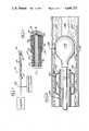
- FIG. 1is a schematic view of a system including a medical device embodying the present invention
- FIG. 2is an enlarged cross-sectional elevational view of the distal end portion of the medical device of FIG. 1;
- FIG. 3is another enlarged elevational view, partly in section, of a further alternative embodiment of the medical device shown received within a blood vessel having a constriction;
- FIG. 4is an enlarged elevational view, partly in section, of the distal end portion of a further alternative embodiment for the medical device
- FIG. 5is further enlarged cross-sectional view taken generally along plane 5--5 of FIG. 4 showing the internal structure of the medical device of FIG. 4;
- FIG. 6is an elevational view of a further alternative embodiment for the medical device
- FIG. 7is an enlarged cross-sectional view taken generally along plane 7--7 of FIG. 6 showing the internal structure of the medical device of FIG. 6;
- FIG. 8is a cross-sectional view of a still further embodiment for the medical device.
- the present inventionis a medical device for delivering and applying localized heat to a site in a patient's body.
- the heatcan be used to stop bleeding or remove or alter a material such as tissue or deposit in the body.
- the material being alteredcan be any solid or semi-solid substance found in the body including living tissue or deposits such as clots, fat or arteriosclerotic plaque.
- FIGS. 1 and 2show a medical device 10 embodying the present invention and including an elongated light transmitting conduit 12 such as an optical fiber or a microwave channel or waveguide, having a proximal end 14 and a distal end 16.
- a heat generating element 18is mounted with respect to the distal end 16 of the conduit 12 such that light transmitted by the fiber is absorbed and converted by the element into heat.
- the lightis emitted by the distal end 16 of the conduit and is received and collected by a light receiving surface 20 on the element 18.
- the element 18is preferably mounted on the distal end 16 of the conduit 12 and retained in that position by appropriate means discussed in more detail below. Mounting the element 18 directly on the conduit 12 insures that the light is properly delivered and the element will not become disengaged from the conduit.
- the conduit 12is preferably a single, flexible light-transmitting fiber such as used in fiberoptic devices and generally has a total exterior diameter of about one millimeter or less.
- a single fibergenerally has the rigidity needed to press the element into a deposit or tissue. Larger or smaller fibers can be used depending on the available area in a patient.
- the single, light-transmitting fiber 13includes a fiber core 22 surrounded by cladding 28. The internal reflection caused by the cladding 28 should be such that the fiber 13 has a low divergence as the light exits the distal end 16.
- the core 22 and the cladding 28are made of glass, e.g. silica quartz with a combined diameter of less than about 0.5 millimeter to about 1.0 millimeter.
- Substantially all of the light exiting the distal end 16should be directed forward to be absorbed by the light receiving surface 20. This generates the majority of the heat at the forward end of the heat generating element 18 where it is needed while minimizing the heat on the rearward portions of the element where it could otherwise be detrimental to the fiber 13.
- the fiberalso includes a jacket 26 which surrounds the cladding 28 and is held in place by a resin coating 24.
- the external jacket 26is usually made of a flexible plastic material such as poly(ethylene) or poly(tetrafluoroethylene). This also provides a flexible and smooth surface allowing easy manipulation of the medical device. Fiber optic bundles are not prefered since the glue between individual fibers limits the amount of light which can be transmitted without melting of the bundle.
- the conduit 12should be flexible yet sufficiently resilient so that it is possible to push the conduit along a lumen to drive the heat generating element 18 into and through an obstruction.
- One such suitable conduitis a fiber optic having a core diameter of 0.4 millimeters which is marketed under the trademark Med 400 by Quartz Products Corporation of Plainfield, N.J.
- the forward portion of the heat generating element 18is preferably generally rounded on its exterior surface to facilitate pressing the element into and through softened body material.
- the heat generating elementcan alternatively have other shapes as desired including oblong or eccentric with respect to the axis of the fiber or even generally crescent-shaped. Such an eccentric or oblong shape can be rotated to generate an even larger channel through an obstruction.
- a crescent-shaped elementallows for fluid flow and viewing past the element.
- the element 18is preferably made of metal such as surgical stainless steel, but could also be made of a combination of thermally conductive and insulating material such as metal and ceramic.
- the inside light receiving surface 20is preferably treated, e.g., oxidized, to increase its coefficient of emissivity to about 0.95 or greater to further increase the absorption of light by the element 18.
- the surface 20can be treated by being coated by a material having a high coefficient of emissivity such as lamp or carbon black.
- the exterior surface of the heat generating element 18is preferably coated with a non-stick or release surface such as poly(tetrafluoroethylene) to provide easy release from the tissue poly(tetrafluoroethylene) should only be used for operating temperatures below about 300 degrees C.
- the distal end 16 of the conduit 12is preferably positioned or received in cavity 30 defined by the rear portion of the heat generating element 18.
- the element 18can be retained on the distal end 16 by appropriate means for mounting such as an adhesive, an appropriate locking means, or a combination of both.
- the locking meansis preferably at least one inwardly extending, peripheral ridge 34 on the element 18 received in a complimentary groove 36 defined by the conduit 12.
- the groove 36should extend into the jacket 26 but not into either the core 22 or the cladding 28.
- the adhesivesuch as hardened epoxy resin can be used to retain the element 18 on the conduit 12 while the ridges 34 are crimped into the groove. Since some adhesives may become ineffective under intense heat, the locking means provides a backup to ensure the element remains in place.
- the heat generating element 18has sufficient mass to avoid burn-through during use. However, the mass is not so great as to materially slow its heating rate. For this reason, it is advantageous to place the thickest portion of material in the forward portion of the element 18 where the light infringes.
- a minimum amount of space between the distal end 16 of the fiber and the light receiving surface 20 of the element 18reduces the presence of other matter such as air or liquid which, if present in excess may require venting due to expansion as a result of the heat generated. Where such a space is provided, one or more vents are supplied to provide communication between the space and the outside surface of the element to the ambient surroundings.
- the distal end 16 of the fiberis preferably spaced no more than 2 diameters of the core 22 away from the light receiving surface 20. Where the core is about 0.5 millimeters, this spacing should be no more than about 1 millimeter. This relatively close spacing insures that substantially all of the light is received on the forward light receiving surface 20 and is not dispersed on the inside side walls of the cavity 30.
- the medical devicecan serve as part of a system which, as shown in FIG. 1, includes a light source such as a laser associated with the proximal end 14 of the fiber 13.
- the light sourceis chosen to deliver sufficient light energy to raise the temperature of the element 18 to soften material causing an obstruction or to destroy tissue.
- the systemfurther includes temperature sensing means such as a pyrometer also associated with the proximal end 14 of the fiber for measuring the temperature of the element 18. Both the light source and temperature sensing means can be associated with the proximal end 14 of the fiber 13 by a beam splitting means 42.
- the beam splitting means 42can be a partial mirror or a system such as a rotating or movable mirror. When the mirror is in a first position the laser light is directed into the fiber 13. After the laser is deactivated, the mirror is then placed in a second position to direct the resulting radiation or glow of the element 18 emitted by the fiber proximal end 14 to the pyrometer.
- the laserproduces the light which is converted by the heat generating element 18 into heat.
- the word lightis used in its broad sense, meaning electromagnetic radiation which propagates through space and includes not only visible light, but also infrared, ultraviolet and microwave radiation.
- the laseris preferably used intermittently with temperature measurements made between uses. By monitoring the glow of the heated element 18 it is also possible to provide an advance warning of approaching burn-through where the element 18 has been provided with a layer of different metallic or non-metallic material 46 embedded within the forward portion of the element 18.
- the lightcan enter the fiber continuously or intermittently, as desired, to maintain the element 18 above a predetermined temperature such that it is capable of softening a plaque deposit or cauterizing bleeding tissue.
- rapid heating of the element 18is preferred since this allows the softening and removal of obstructing material while minimizing the amount of heat transferred to the tissues surrounding the blood vessel.
- a slower heating ratereleases a greater total amount of energy into the entire tissue area while a rapid heating rate releases less total energy, but concentrates it in a small area within the material to be softened and removed.
- the elementcan be first heated i.e., light transmission begun, and then contacted with the deposit. This minimizes heat dissipation into the surrounding tissue and allows the element to reach a higher temperature before contact.
- FIG. 3An alternative embodiment for the medical device 110 is shown in FIG. 3.
- the medical deviceis shown received within a blood vessel 152 having a deposit 154 which reduces the operative size of the blood vessel to a relatively small constricted channel 156.
- the medical device 110includes a light transmitting conduit 112 and a heat generating element 118 substantially as described above.
- the element 118includes an enlarged head portion to create a channel of relatively larger diameter in the deposit 154.
- the medical device 110also includes an elongated tube 158 having a proximal portion (not shown) and a distal portion 162 and defining a passageway 164 along its length.
- the elongated tube 158allows for positioning the light transmitting conduit 112 and heated element 118 in a lumen such as blood vessel 152 by passing the tube through the skin and muscle layers of the patient into the blood vessel.
- the conduit 112is slidingly received in the tube 158 so that it can be moved longitudinally with respect to the tube and the element 118 extended beyond the distal portion 162 of the tube.
- the elementcan be of such size that it may be received within the passageway 164 during the placement of the device within the blood vessel 152.
- the tube 158is then first located in a vessel and a conduit 112 with a relatively small heated element as shown in FIG. 2 inserted into the tube 158.
- the element 118 as shown in FIG. 3can be relatively larger in cross section than the passageway 164 to create a larger channel in an obstruction.
- the heated elementcan even be larger than the outer diameter of the tube 158 allowing the tube to be advanced progressively as the element is repeatedly pressed forward to create a longer channel.
- the heated elementis larger in cross section than the passageway 164, the element can rest against the opening of the tube distal portion 162 during insertion into the blood vessel.
- the defined annular passageway 164permits the introduction of fluid into the blood vessel such as a radiopaque liquid which allows fluoroscopic study of the size and location of the deposit 154 and the constricted channel 156.
- the element 118, also radiopaquecan also be fluoroscopically tracked.
- the conduit 112 and tube 158can also be provided with radiopaque markings along their lengths for fluoroscopic tracking.
- the tube 158preferably carries a blood flow occlusion means such as an inflatable balloon 166 positioned circumferentially about the tube on the distal portion 162.
- the balloon 166is preferably made of a suitable flexible plastic material and is inflated to contact and seal with the blood vessel wall by introducing a fluid such as carbon dioxide through a channel 168 defined by a thickened wall of the tube 158.
- a fluidsuch as a physiologically tolerable flushing liquid can be introduced through passageway 164.
- Suitable liquidsinclude a saline solution, a dextrose solution, or an oxygen bearing liquid which provides oxygen to tissue downstream of the balloon.
- a radiopaque liquidcan also be introduced for fluoroscopic viewing as described above.
- a physiologically tolerable gas such as carbon dioxidecan also be introduced through the passageway 164 such that it surrounds the element 118 with a temporary gas bubble to minimize dissipation of heat from the element which otherwise would be directed into blood or radiopaque liquid. This also avoids damage to the blood.
- the gas bubble or introduced liquidcan be withdrawn by suction through the passageway 164 after the procedure is over. Any debris generated can also be removed by suction.
- FIGS. 4 and 5A still further alternative embodiment for the medical device 210 is shown in FIGS. 4 and 5.
- the heat generating element 218is mounted on the distal end 216 of the light transmitting conduit 212.
- the resin coating 224 and jacket 226have been trimmed back from the distal end 216 of the fiber 213 leaving a section of the clading 228 surrounding the fiber core 222 open to the sides.
- the removal of the resin coating 224 and jacket 226 from the end portion of the fiber core 222creates a spacing between the fiber core 222 and the element 218.
- the air in this spaceserves as an insulator between the element 218 and the fiber 213.
- Suitable other insulating materialscan also be located between the element and fiber.
- Directing substantially all of the emitted light onto the light receiving surface 220 on the forward portion of the element 218 together with this spacingminimizes the conduction of heat from the element 218 to the jacket 226 of the conduit 212.
- a section of reduced metal thicknesssuch as caused by a peripheral notch 272 can be provided. Because there is less metal in the area of the notch 272, a lesser cross-sectional area for heat conduction is available and there is less transfer of heat per unit time toward the rearward portion of the element 218.
- the heat generating element 218is retained on the conduit 212 by one or more inwardly extending ridges 234 received within corresponding peripheral grooves 236 in the jacket 226.
- the distal portion 262 of tube 258engages the rear portion of the heat generating element 218 also to help retain the element on the conduit 212.
- the tube 258can be made of the same material as the jacket 226, and is preferably a heat resisting plastic such as poly(tetrafluoroethylene).
- the tube 258defines passageway 264 along its length through which the light transmitting conduit 212 is received.
- the rear portion of the heat generating element 218preferably defines at least one, and optimally a plurality of flutes 274 which are in fluid communication with the tube passageway 264.
- the introduced fluidis not only useful for clearing or removing debris produced about the heat generating element 218 when in use, but also helps to cool the rear portion of the element 218.
- the elongated structure of the heat generating element 218assists manipulation of the device 210 as when it is passed through a channel defined by an endoscope.
- a vent 276can be provided on the side of the element in communication with the cavity 230.
- the medical device 310includes a heat generating element 318 mounted on the end of a light transmitting conduit 312 which is slidably received within an elongated tube 358.
- An inflatable balloon 366is also included on the distal portion 362 of the tube 358.
- Mounted on the proximal portion 360 of the tubeis an assembly including an eyepiece 380 that forms part of a viewing system.
- the viewing systemalso includes a fiberoptic viewing conduit 382 and illumination conduit 388 carried by the tube 358 together with the appropriate lens devices well-known in the art carried both by the assembly 378 and the distal end 362 of the tube.
- the conduit 312is slidably carried by the tube 358 and includes a connector 384 on its proximal end for linking with appropriate laser.
- the tube 358also defines a channel 368 for inflating the balloon 366 and a flushing or suction passageway 364 for introducing fluids into a lumen.
- the passageway 364can also be used in conjunction with a guide wire to direct the device into the patient.
- the distal portion of the medical deviceis inserted into a patient and positioned in the approximate desired location.
- the balloon 366is then inflated to occlude the blood vessel.
- a clear fluidsuch as carbon dioxide or a liquid can then be introduced through the passageway 364 to allow viewing through the viewing system.
- Appropriate meanscan also be provided to wash the distal end of the viewing system. This allows visualization of the occlusion to be made prior to contact with the heat generating element 318 and also to determine the size of the size of the channel which has been opened by the heat generating element after it has been withdrawn.
- the light transmitting conduit 412extends through the elongated tube 458 and is centered within the defined passageway 464 along the central axis of the tube by centering means such as three longitudinal ridges 492 extending inward from the tube wall.
- Each ridge 492preferably defines a channel 468 which can be used to inflate a balloon on the tube or for introduction of fluid through the distal end of the tube.
- the ridges 492can be extrusion molded unitary with the remainder of the tube 458.
- the ridges 492center the conduit 412 and the element mounted on its distal end so that the element can be directed into the center of a lumen and avoid the lumen walls.
- the ridges 492also minimize heat transfer from the conduit 412 to the tube 458 and hence to the lumen.
- the flow of a fluid through the passageway 464 about the conduit 412also lowers its temperature during use.
- the preferred lasersare Argon and Neodyminum-YAG. Tests were done with a Med 400 fiber optic (0.4 millimeter diameter core) 1.8 meters in length and equiped with a stainless steel heat generating element having the configuration as shown in FIG. 4 and a length of about 9 millimeters, a diameter of about 1.0 millimeters, and a mass of about 0.1 grams.
- a 68 watt Neodyminum-YAG laser manufactured by Messerschmidt of Kunststoff, West Germanyraised the temperature of the heat generating element from room temperature to about 500 degrees C. in about 0.5 seconds.
- a 6 watt Argon laser manufactured by Laser Ionics of Orlando, Fla.raised the temperature of the heat generating element to 654 degrees C. from a base line temperature of 25 degrees C. in five seconds.
- a two second burst from a 6 watt Argon laserraised the temperature of the heat generating element to 231 degrees from a base line temperature of 24 degrees C.
- Measurements of laser intensitywere made at the proximal end of the fiber optic by using a laser power meter Model 201 made by Coherent Radiation of Palo Alto, Calif. Temperature measurements of the element were made using a 30 gauge Model HPY-1 hypodermic thermocouple available from Omega Engineering of Stanford, Conn. and a digital temperature meter available from Analogic Corporation of Wakefield, Mass.
- Testswere also made of the energy transfer by the device into liquid samples using both blood and tap water samples.
- Bloodwas withdrawn from several patients in a process which mixed approximately 7 milliliters of blood with 0.07 milliliters of 15 percent ethylene diamine tetraacetic acid (EDTA). The blood was pooled by mixing to obtain a uniform larger quantity.
- Conical polystyrene sample cups having a capacity of 2.0 milliliterswere divided into two groups and filled respectively with 0.5 milliliters of tap water for 0.5 milliliters of blood.
- the heat generating elementwas then immersed in the water or blood together with the thermocouple temperature probe. Tests were then made at 1 to 6 watts with an Argon laser for periods of 10 to 60 seconds to determine the heat generation of the device. Seven samples were tested for each combination of energy and time. The base line temperature for each test was 19-20 degrees C.
- a 10 second burst of laser energy at 1 watt intensityraised the temperature of the water samples to an average of 33 degrees C. and the blood samples to an average of 46 degrees C.
- a 1 watt burst for 60 secondsraised the temperature of the water samples to an average of 52 degrees C. and blood to an average temperature of 66 degrees C.
- Testswere also carried out to measure the effectiveness of the medical device on artery walls.
- a particularly surprising result of those experimentswas the relative thermal insulation provided by an artery. It was found that a substantial temperature gradient existed across the wall of the artery when the device was used. This demonstrates that it is possible to remove an obstruction within an artery using the medical device of the present invention with a minimum amount of trauma to the surrounding tissue.
- Bilateral cut-downswere performed on the femoral and carotid arteries of a male Shepherd-mix dog 82 pounds in weight.
- a Med 400 fiber having a stainless steel heat generating element mounted on the end as described abovewas inserted into the artery and positioned adjacent two of three sutures located in the right femoral artery to serve as markers.
- An Argon laser at a power level of 6 wattswas used for 5-second bursts.
- the temperature increase of the artery and the heated elementwere measured in separate tests in the same artery.
- the thermocouple temperature probe located in the artery wall adjacent the heat generating elementshowed a temperature of 44 degrees C. after use of the laser from a base line temperature of 31.5 degrees C.
- the temperature of the heat generating elementwas measured after laser use at 66 degrees C. from a base line temperature of 34 degrees C.
- the temperature of the arterial wallincreased from a base line temperature of 32 degrees C. to 36 degrees C.
- the temperature of the element within the arteryincreased from a base line temperature of 32.5 degrees C. to a final temperature of 47 degrees C.
- the arteryhas particularly good insulating qualities which protect the surrounding tissue.
- the heat generating elementcan be raised to a sufficient temperature to soften a deposit such as a fat without extensive damage to an artery. It has also been demonstrated that the insulation quality of arterial wall substantially reduces trauma to any adjacent tissue.
- the medical devicecan be used to cauterize bleeding or remove tissue in surgical procedures where there is little available space.
- One such procedureis surgery being conducted by means of an endoscope in a body cavity.
- the medical devicecan be directed along a channel defined by the endoscope until the heat generating element has been properly located in contact with the tissue. After the operator is satisfied that the element is properly and safely located, the element can be quickly heated. This provides safety since the heat energy is not conducted to the tissue until the operator can be certain that otherwise healthy tissue will not be damaged.
- Such use of the medical device of the present inventioncan be made in the treatment of a bleeding ulcer with the assistance of a gastrofiberscope.
- the medical device embodying this inventioncan also be used to deliver localized heat within a lumen such as a blood vessel.
- the heatcan be used to open a clot or soften and remove plaque and fatty deposits which are found in blood vessels.
- the heated elementsoftens the deposit material so that the element may be pressed into and through the plaque to enlarge the channel in a constriction or create a channel through an obstruction.
Landscapes
- Physics & Mathematics (AREA)
- Optics & Photonics (AREA)
- Engineering & Computer Science (AREA)
- Health & Medical Sciences (AREA)
- Surgery (AREA)
- Life Sciences & Earth Sciences (AREA)
- Plasma & Fusion (AREA)
- Mechanical Engineering (AREA)
- Electromagnetism (AREA)
- Animal Behavior & Ethology (AREA)
- Nuclear Medicine, Radiotherapy & Molecular Imaging (AREA)
- Biomedical Technology (AREA)
- Heart & Thoracic Surgery (AREA)
- Medical Informatics (AREA)
- Molecular Biology (AREA)
- Otolaryngology (AREA)
- General Health & Medical Sciences (AREA)
- Public Health (AREA)
- Veterinary Medicine (AREA)
- Thermal Sciences (AREA)
- Laser Surgery Devices (AREA)
- Radiation-Therapy Devices (AREA)
- Surgical Instruments (AREA)
Abstract
Description
TABLE I ______________________________________ Laser Baseline O.D. Of Vessel Final O.D. of Vessel Duration Temp Pre-Lasing Temp Post-Lasing (Secs) (°C.) (mm) (°C.) (mm) ______________________________________ 1 29 5.2 138 5.2 2 28 5.3 87 4.0 3 25 5.1 89 4.1 ______________________________________
TABLE II ______________________________________ Laser Baseline O.D. Of Vessel Final O.D. of Vessel Duration Temp Pre-Lasing Temp Post-Lasing (Secs) (°C.) (mm) (°C.) (mm) ______________________________________ 1 38 5.0 38 5.1 2 37 5.0 36 5.0 3 38 4.8 40 4.9 ______________________________________
Claims (59)
Priority Applications (13)
| Application Number | Priority Date | Filing Date | Title |
|---|---|---|---|
| US06/503,783US4646737A (en) | 1983-06-13 | 1983-06-13 | Localized heat applying medical device |
| IT8448331AIT8448331A0 (en) | 1983-06-13 | 1984-06-06 | MEDICAL DEVICE FOR THE LOCALIZED APPLICATION OF HEAT FOR REMOVAL OR CAUTERIZATION PURPOSES |
| CA000456416ACA1253216A (en) | 1983-06-13 | 1984-06-12 | Localized heat applying medical device |
| ES533326AES8600916A1 (en) | 1983-06-13 | 1984-06-12 | Localized heat applying medical device. |
| PCT/US1984/000902WO1984004879A1 (en) | 1983-06-13 | 1984-06-13 | Localized heat applying medical device |
| JP1985600005UJPS60500014U (en) | 1983-06-13 | 1984-06-13 | |
| EP84902561AEP0145780B1 (en) | 1983-06-13 | 1984-06-13 | Localized heat applying medical device |
| DE8484902561TDE3482752D1 (en) | 1983-06-13 | 1984-06-13 | MEDICAL DEVICE FOR APPLYING A LOCAL HEAT. |
| BR8406928ABR8406928A (en) | 1983-06-13 | 1984-06-13 | MEDICAL DEVICE FOR LOCATED HEAT APPLICATION |
| AU30657/84AAU3065784A (en) | 1983-06-13 | 1984-06-13 | Localized heat applying medical device |
| ES543208AES8707423A1 (en) | 1983-06-13 | 1985-05-16 | Localized heat applying medical device. |
| US06/750,683US4662368A (en) | 1983-06-13 | 1985-06-28 | Localized heat applying medical device |
| US07/016,248US4773413A (en) | 1983-06-13 | 1987-02-19 | Localized heat applying medical device |
Applications Claiming Priority (1)
| Application Number | Priority Date | Filing Date | Title |
|---|---|---|---|
| US06/503,783US4646737A (en) | 1983-06-13 | 1983-06-13 | Localized heat applying medical device |
Related Child Applications (1)
| Application Number | Title | Priority Date | Filing Date |
|---|---|---|---|
| US06/750,683Continuation-In-PartUS4662368A (en) | 1983-06-13 | 1985-06-28 | Localized heat applying medical device |
Publications (1)
| Publication Number | Publication Date |
|---|---|
| US4646737Atrue US4646737A (en) | 1987-03-03 |
Family
ID=24003491
Family Applications (1)
| Application Number | Title | Priority Date | Filing Date |
|---|---|---|---|
| US06/503,783Expired - Fee RelatedUS4646737A (en) | 1983-06-13 | 1983-06-13 | Localized heat applying medical device |
Country Status (10)
| Country | Link |
|---|---|
| US (1) | US4646737A (en) |
| EP (1) | EP0145780B1 (en) |
| JP (1) | JPS60500014U (en) |
| AU (1) | AU3065784A (en) |
| BR (1) | BR8406928A (en) |
| CA (1) | CA1253216A (en) |
| DE (1) | DE3482752D1 (en) |
| ES (2) | ES8600916A1 (en) |
| IT (1) | IT8448331A0 (en) |
| WO (1) | WO1984004879A1 (en) |
Cited By (97)
| Publication number | Priority date | Publication date | Assignee | Title |
|---|---|---|---|---|
| WO1987004611A1 (en)* | 1986-01-30 | 1987-08-13 | The Beth Israel Hospital Association | Optical fiber metallic tip intravascular laser coagulation |
| DE3723227C1 (en)* | 1987-07-14 | 1988-10-20 | Messerschmitt Boelkow Blohm | Radiation coagulator |
| US4825035A (en)* | 1986-09-20 | 1989-04-25 | Mitsubishi Denki Kabushiki Kaisha | Control apparatus for energy beam hardening |
| US4860743A (en)* | 1986-10-27 | 1989-08-29 | University Of Florida | Laser method and apparatus for the recanalization of vessels and the treatment of other cardiac conditions |
| US4878492A (en)* | 1987-10-08 | 1989-11-07 | C. R. Bard, Inc. | Laser balloon catheter |
| US4899741A (en)* | 1987-01-14 | 1990-02-13 | Hgm Medical Laser Systems, Inc. | Laser heated probe and control system |
| EP0311295A3 (en)* | 1987-10-07 | 1990-02-28 | University College London | Improvements in surgical apparatus |
| WO1990004949A1 (en)* | 1988-11-10 | 1990-05-17 | Xintec Corporation | Improved laser-heated intravascular cautery cap |
| JPH02156941A (en)* | 1988-09-23 | 1990-06-15 | Trimedyne Laser Syst Inc | Heating catheter with thermal barrier |
| US4949244A (en)* | 1987-02-18 | 1990-08-14 | Hitachi, Ltd. | Storage system |
| US5009655A (en)* | 1989-05-24 | 1991-04-23 | C. R. Bard, Inc. | Hot tip device with optical diagnostic capability |
| US5019075A (en)* | 1984-10-24 | 1991-05-28 | The Beth Israel Hospital | Method and apparatus for angioplasty |
| US5041109A (en)* | 1986-10-27 | 1991-08-20 | University Of Florida | Laser apparatus for the recanalization of vessels and the treatment of other cardiac conditions |
| US5061265A (en)* | 1989-06-20 | 1991-10-29 | University Of Florida | Laser treatment apparatus and method |
| US5103804A (en)* | 1990-07-03 | 1992-04-14 | Boston Scientific Corporation | Expandable tip hemostatic probes and the like |
| US5122137A (en)* | 1990-04-27 | 1992-06-16 | Boston Scientific Corporation | Temperature controlled rf coagulation |
| US5147353A (en)* | 1990-03-23 | 1992-09-15 | Myriadlase, Inc. | Medical method for applying high energy light and heat for gynecological sterilization procedures |
| US5154707A (en)* | 1987-02-27 | 1992-10-13 | Rink Dan L | Method and apparatus for external control of surgical lasers |
| US5188632A (en)* | 1984-12-07 | 1993-02-23 | Advanced Interventional Systems, Inc. | Guidance and delivery system for high-energy pulsed laser light |
| US5226430A (en)* | 1984-10-24 | 1993-07-13 | The Beth Israel Hospital | Method for angioplasty |
| WO1993025136A3 (en)* | 1992-06-05 | 1994-02-17 | Albert K Chin | Method and apparatus for prostatic treatment |
| US5322507A (en)* | 1992-08-11 | 1994-06-21 | Myriadlase, Inc. | Endoscope for treatment of prostate |
| US5419767A (en)* | 1992-01-07 | 1995-05-30 | Thapliyal And Eggers Partners | Methods and apparatus for advancing catheters through severely occluded body lumens |
| US5487740A (en)* | 1994-03-02 | 1996-01-30 | Energy Life Systems Corporation | Laser device for ablation of human tissue |
| US5496311A (en)* | 1988-10-28 | 1996-03-05 | Boston Scientific Corporation | Physiologic low stress angioplasty |
| USRE35330E (en)* | 1989-08-28 | 1996-09-17 | University Of Kansas Medical Center | Hot tip catheter assembly |
| US5607420A (en)* | 1992-02-25 | 1997-03-04 | Surgical Laser Technologies, Inc. | Surgical tool for use with a contact laser |
| US5649924A (en)* | 1988-06-10 | 1997-07-22 | Trimedyne, Inc. | Medical device for irradiation of tissue |
| WO1998033555A1 (en) | 1997-01-31 | 1998-08-06 | Radiance Medical Systems, Inc. | Radiation delivery balloon |
| US5807389A (en)* | 1991-08-16 | 1998-09-15 | Myriadlase, Inc. | Laterally reflecting tip for laser transmitting fiber |
| US5814784A (en)* | 1992-01-13 | 1998-09-29 | Powerlasers Ltd. | Laser-welding techniques using pre-heated tool and enlarged beam |
| WO1998044854A1 (en)* | 1997-04-07 | 1998-10-15 | Broncus Technologies, Inc. | Bronchial stenter |
| US5833683A (en)* | 1996-01-12 | 1998-11-10 | Surgical Laser Technologies, Inc. | Laterally-emitting laser medical device |
| US5843071A (en)* | 1986-12-18 | 1998-12-01 | Bath; Patricia E. | Method and apparatus for ablating and removing cataract lenses |
| US5897551A (en)* | 1990-03-23 | 1999-04-27 | Myriadlase, Inc. | Medical device for applying high energy light and heat for gynecological sterilization procedures |
| US5921963A (en)* | 1992-04-29 | 1999-07-13 | Mali-Tech Ltd. | Skin piercing devices for medical use |
| US5989243A (en)* | 1984-12-07 | 1999-11-23 | Advanced Interventional Systems, Inc. | Excimer laser angioplasty system |
| US6073052A (en)* | 1996-11-15 | 2000-06-06 | Zelickson; Brian D. | Device and method for treatment of gastroesophageal reflux disease |
| US6106516A (en)* | 1997-10-30 | 2000-08-22 | Sonique Surgical Systems, Inc. | Laser-assisted liposuction method and apparatus |
| US6139571A (en)* | 1997-07-09 | 2000-10-31 | Fuller Research Corporation | Heated fluid surgical instrument |
| US6196963B1 (en) | 1999-03-02 | 2001-03-06 | Medtronic Ave, Inc. | Brachytherapy device assembly and method of use |
| US20010001314A1 (en)* | 1997-06-13 | 2001-05-17 | Arthrocare Corporation | Electrosurgical systems and methods for recanalization of occluded body lumens |
| US6283989B1 (en) | 1997-04-07 | 2001-09-04 | Broncus Technolgies, Inc. | Method of treating a bronchial tube with a bronchial stenter having diametrically adjustable electrodes |
| US6283988B1 (en) | 1997-04-07 | 2001-09-04 | Broncus Technologies, Inc. | Bronchial stenter having expandable electrodes |
| US20020156471A1 (en)* | 1999-03-09 | 2002-10-24 | Stern Roger A. | Method for treatment of tissue |
| US6488673B1 (en) | 1997-04-07 | 2002-12-03 | Broncus Technologies, Inc. | Method of increasing gas exchange of a lung |
| US6554824B2 (en) | 2000-12-15 | 2003-04-29 | Laserscope | Methods for laser treatment of soft tissue |
| US20030084907A1 (en)* | 1993-05-10 | 2003-05-08 | Arthrocare Corporation | Systems and methods for electrosurgical dissection and harvesting of tissue |
| US6582423B1 (en) | 1997-06-13 | 2003-06-24 | Arthrocare Corporation | Electrosurgical systems and methods for recanalization of occluded body lumens |
| US20030130649A1 (en)* | 2000-12-15 | 2003-07-10 | Murray Steven C. | Method and system for treatment of benign prostatic hypertrophy (BPH) |
| US20030135205A1 (en)* | 2000-12-15 | 2003-07-17 | Davenport Scott A. | Method and system for photoselective vaporization of the prostate, and other tissue |
| US20030195592A1 (en)* | 2002-04-12 | 2003-10-16 | Michael Black | Temperature controlled heating device and method to heat a selected area of a biological body |
| US20030199866A1 (en)* | 1996-01-05 | 2003-10-23 | Stern Roger A. | Method and kit for treatment of tissue |
| US20030212393A1 (en)* | 1996-01-05 | 2003-11-13 | Knowlton Edward W. | Handpiece with RF electrode and non-volatile memory |
| US20030216717A1 (en)* | 2002-02-22 | 2003-11-20 | Laserscope | Method and system for photoselective vaporization for gynecological treatments |
| US20040002704A1 (en)* | 1996-01-05 | 2004-01-01 | Knowlton Edward W. | Treatment apparatus with electromagnetic energy delivery device and non-volatile memory |
| US20040002705A1 (en)* | 1996-01-05 | 2004-01-01 | Knowlton Edward W. | Methods for creating tissue effect utilizing electromagnetic energy and a reverse thermal gradient |
| US20040000316A1 (en)* | 1996-01-05 | 2004-01-01 | Knowlton Edward W. | Methods for creating tissue effect utilizing electromagnetic energy and a reverse thermal gradient |
| US20040030332A1 (en)* | 1996-01-05 | 2004-02-12 | Knowlton Edward W. | Handpiece with electrode and non-volatile memory |
| US20040031494A1 (en)* | 1998-06-10 | 2004-02-19 | Broncus Technologies, Inc. | Methods of treating asthma |
| US20040034346A1 (en)* | 1996-01-05 | 2004-02-19 | Stern Roger A. | RF device with thermo-electric cooler |
| US20040044337A1 (en)* | 2002-08-27 | 2004-03-04 | Gal Shafirstein | Conductive interstitial thermal therapy device |
| US20040111087A1 (en)* | 1999-03-09 | 2004-06-10 | Stern Roger A. | Handpiece for treatment of tissue |
| US20040111137A1 (en)* | 1996-08-13 | 2004-06-10 | Oratec Interventions, Inc., A Delaware Corporation | Method of treating intervertebral disc |
| US20040127963A1 (en)* | 1999-01-25 | 2004-07-01 | Uchida Andy H. | Intervertebral decompression |
| US20040186535A1 (en)* | 1999-06-30 | 2004-09-23 | Knowlton Edward W. | Fluid delivery apparatus |
| GB2409816A (en)* | 2004-01-12 | 2005-07-13 | Martin Lister | Cauterising tool |
| US20050187579A1 (en)* | 1997-04-07 | 2005-08-25 | Asthmatx, Inc. | Method for treating an asthma attack |
| US7022121B2 (en) | 1999-03-09 | 2006-04-04 | Thermage, Inc. | Handpiece for treatment of tissue |
| US20060167445A1 (en)* | 2002-08-27 | 2006-07-27 | Gal Shafirstein | Selective conductive interstitial thermal therapy device |
| US20060247726A1 (en)* | 2000-10-17 | 2006-11-02 | Asthmatx, Inc. | Control system and process for application of energy to airway walls and other mediums |
| US20060254600A1 (en)* | 2000-03-27 | 2006-11-16 | Asthmatx, Inc. | Methods for treating airways |
| US7189230B2 (en) | 1996-01-05 | 2007-03-13 | Thermage, Inc. | Method for treating skin and underlying tissue |
| US20070083197A1 (en)* | 1998-01-07 | 2007-04-12 | Asthmatx, Inc. | Method for treating an asthma attack |
| US20070100390A1 (en)* | 2000-10-17 | 2007-05-03 | Asthmatx, Inc. | Modification of airways by application of energy |
| US20070102011A1 (en)* | 1998-06-10 | 2007-05-10 | Asthmatx, Inc. | Methods of evaluating individuals having reversible obstructive pulmonary disease |
| US20070123958A1 (en)* | 1998-06-10 | 2007-05-31 | Asthmatx, Inc. | Apparatus for treating airways in the lung |
| US7452358B2 (en) | 1996-01-05 | 2008-11-18 | Thermage, Inc. | RF electrode assembly for handpiece |
| US20080287940A1 (en)* | 2007-05-14 | 2008-11-20 | Hunter Lowell D | Fiber Pole Tip |
| US20080287934A1 (en)* | 2007-05-15 | 2008-11-20 | Hunter Lowell D | Laser Handle and Fiber Guard |
| US20090069797A1 (en)* | 1997-04-07 | 2009-03-12 | Asthmatx, Inc. | Bipolar devices for modification of airways by transfer of energy |
| US7505812B1 (en) | 1993-05-10 | 2009-03-17 | Arthrocare Corporation | Electrosurgical system for treating restenosis of body lumens |
| US20090306637A1 (en)* | 2008-06-04 | 2009-12-10 | Vnus Medical Technologies, Inc. | Energy devices and methods for treating hollow anatomical structures |
| US8181656B2 (en) | 1998-06-10 | 2012-05-22 | Asthmatx, Inc. | Methods for treating airways |
| US8483831B1 (en) | 2008-02-15 | 2013-07-09 | Holaira, Inc. | System and method for bronchial dilation |
| US8740895B2 (en) | 2009-10-27 | 2014-06-03 | Holaira, Inc. | Delivery devices with coolable energy emitting assemblies |
| US8808280B2 (en) | 2008-05-09 | 2014-08-19 | Holaira, Inc. | Systems, assemblies, and methods for treating a bronchial tree |
| US8911439B2 (en) | 2009-11-11 | 2014-12-16 | Holaira, Inc. | Non-invasive and minimally invasive denervation methods and systems for performing the same |
| US9149328B2 (en) | 2009-11-11 | 2015-10-06 | Holaira, Inc. | Systems, apparatuses, and methods for treating tissue and controlling stenosis |
| US9272132B2 (en) | 2012-11-02 | 2016-03-01 | Boston Scientific Scimed, Inc. | Medical device for treating airways and related methods of use |
| US9283374B2 (en) | 2012-11-05 | 2016-03-15 | Boston Scientific Scimed, Inc. | Devices and methods for delivering energy to body lumens |
| US9339618B2 (en) | 2003-05-13 | 2016-05-17 | Holaira, Inc. | Method and apparatus for controlling narrowing of at least one airway |
| US9398933B2 (en) | 2012-12-27 | 2016-07-26 | Holaira, Inc. | Methods for improving drug efficacy including a combination of drug administration and nerve modulation |
| US9592086B2 (en) | 2012-07-24 | 2017-03-14 | Boston Scientific Scimed, Inc. | Electrodes for tissue treatment |
| US9770293B2 (en) | 2012-06-04 | 2017-09-26 | Boston Scientific Scimed, Inc. | Systems and methods for treating tissue of a passageway within a body |
| US9974607B2 (en) | 2006-10-18 | 2018-05-22 | Vessix Vascular, Inc. | Inducing desirable temperature effects on body tissue |
| US10478247B2 (en) | 2013-08-09 | 2019-11-19 | Boston Scientific Scimed, Inc. | Expandable catheter and related methods of manufacture and use |
Families Citing this family (26)
| Publication number | Priority date | Publication date | Assignee | Title |
|---|---|---|---|---|
| US5041108A (en)* | 1981-12-11 | 1991-08-20 | Pillco Limited Partnership | Method for laser treatment of body lumens |
| US4848336A (en)* | 1981-12-11 | 1989-07-18 | Fox Kenneth R | Apparatus for laser treatment of body lumens |
| US4784132A (en)* | 1983-03-25 | 1988-11-15 | Fox Kenneth R | Method of and apparatus for laser treatment of body lumens |
| IL76285A0 (en)* | 1984-09-17 | 1986-01-31 | Xintec Corp | Laser revascularization device and method of operation therefor |
| US4848339A (en)* | 1984-09-17 | 1989-07-18 | Xintec Corporation | Laser heated intravascular cautery cap assembly |
| CA1266412A (en)* | 1984-10-24 | 1990-03-06 | J. Richard Spears | Method and apparatus for angioplasty |
| GB2175505B (en)* | 1985-05-22 | 1989-10-25 | Bard Inc C R | Wire guided laser catheter |
| FR2582505B1 (en)* | 1985-05-31 | 1990-04-27 | Lefebvre Jean Marc | FIBER OPTIC CATHETER FOR REALIZING LIGHT ENERGY FROM A LASER |
| EP0214712B1 (en)* | 1985-07-31 | 1992-09-02 | C.R. Bard, Inc. | Infrared laser catheter apparatus |
| US4917084A (en)* | 1985-07-31 | 1990-04-17 | C. R. Bard, Inc. | Infrared laser catheter system |
| US4606331A (en)* | 1985-09-03 | 1986-08-19 | Monghan Medical Corporation | Electrode for fiber optic scopes |
| US4654024A (en)* | 1985-09-04 | 1987-03-31 | C.R. Bard, Inc. | Thermorecanalization catheter and method for use |
| GB2182565A (en)* | 1985-11-08 | 1987-05-20 | Micra Ltd | Surgical knives |
| US4834093A (en)* | 1986-02-03 | 1989-05-30 | Littleford Phillip O | Dilation catheter and method |
| US4736743A (en)* | 1986-05-12 | 1988-04-12 | Surgical Laser Technology, Inc. | Vaporization contact laser probe |
| IT1192033B (en)* | 1986-05-13 | 1988-03-31 | Umberto Cavicchi | DEVICE FOR THE GENERATION OF INFRARED RADIATION OPERATING AT CUTANEOUS LEVEL AND DEEP TISSUES IN THE HUMAN BODY |
| AU576428B2 (en)* | 1986-05-16 | 1988-08-25 | Gv Medical Inc. | Laser catheter feed back system |
| US4790311A (en)* | 1986-06-03 | 1988-12-13 | Ruiz Oscar F | Radio frequency angioplasty catheter system |
| EP0335022A1 (en)* | 1988-03-31 | 1989-10-04 | Robert Ginsburg | Vascular catheter |
| US4777951A (en)* | 1986-09-19 | 1988-10-18 | Mansfield Scientific, Inc. | Procedure and catheter instrument for treating patients for aortic stenosis |
| US4760845A (en)* | 1987-01-14 | 1988-08-02 | Hgm Medical Laser Systems, Inc. | Laser angioplasty probe |
| EP0357853A1 (en)* | 1988-09-09 | 1990-03-14 | GV Medical, Inc. | Centering balloon structure for transluminal angioplasty catheter |
| DE3833991A1 (en)* | 1987-05-25 | 1990-04-12 | Messerschmitt Boelkow Blohm | Catheter |
| US5454807A (en)* | 1993-05-14 | 1995-10-03 | Boston Scientific Corporation | Medical treatment of deeply seated tissue using optical radiation |
| DE4341967C2 (en)* | 1993-12-09 | 1997-01-09 | Dornier Medizintechnik | Method for operating a laser |
| DE102018118307A1 (en)* | 2018-07-27 | 2020-01-30 | Bajog Electronic Gmbh | Device for the thermal treatment of biological tissue and method for operating such a device |
Citations (13)
| Publication number | Priority date | Publication date | Assignee | Title |
|---|---|---|---|---|
| US3136310A (en)* | 1960-01-18 | 1964-06-09 | Bausch & Lomb | Optical catheter |
| US4074718A (en)* | 1976-03-17 | 1978-02-21 | Valleylab, Inc. | Electrosurgical instrument |
| DE2826383A1 (en)* | 1978-06-16 | 1979-12-20 | Eichler Juergen | Probe for laser surgery - is tubular and placed against or inserted in tissue, with or without heated end |
| DE2829516A1 (en)* | 1978-07-05 | 1980-01-17 | Messerschmitt Boelkow Blohm | Monitor for medical laser coagulator - detects changes in thermal radiation from irradiated tissue for conversion to temperature values |
| DE2832847A1 (en)* | 1978-07-26 | 1980-02-14 | Sigma Instr Gmbh | Safety device for laser endoscope - has beam directed onto converter connected to comparison circuit to test radiation level before use |
| US4209017A (en)* | 1970-08-13 | 1980-06-24 | Shaw Robert F | Surgical instrument having self-regulating radiant heating of its cutting edge and method of using the same |
| US4233493A (en)* | 1974-05-21 | 1980-11-11 | Nath Guenther | Apparatus for applying intense light radiation to a limited area |
| US4266549A (en)* | 1978-10-12 | 1981-05-12 | Hiroaki Kimura | Laser scalpel |
| US4423726A (en)* | 1980-11-04 | 1984-01-03 | Agency Of Industrial Science & Technology | Safety device for laser ray guide |
| US4437474A (en)* | 1982-07-16 | 1984-03-20 | Cordis Corporation | Method for making multiconductor coil and the coil made thereby |
| US4445892A (en)* | 1982-05-06 | 1984-05-01 | Laserscope, Inc. | Dual balloon catheter device |
| US4448188A (en)* | 1982-02-18 | 1984-05-15 | Laserscope, Inc. | Method for providing an oxygen bearing liquid to a blood vessel for the performance of a medical procedure |
| US4449528A (en)* | 1980-03-20 | 1984-05-22 | University Of Washington | Fast pulse thermal cautery probe and method |
Family Cites Families (2)
| Publication number | Priority date | Publication date | Assignee | Title |
|---|---|---|---|---|
| DE3119322C2 (en)* | 1981-05-15 | 1986-01-23 | Messerschmitt-Bölkow-Blohm GmbH, 8000 München | Probe for sclerosing varicose veins |
| JPS585010U (en)* | 1981-07-02 | 1983-01-13 | 住友電気工業株式会社 | Monitor device for laser equipment that passes output laser light through a light guiding fiber |
- 1983
- 1983-06-13USUS06/503,783patent/US4646737A/ennot_activeExpired - Fee Related
- 1984
- 1984-06-06ITIT8448331Apatent/IT8448331A0/enunknown
- 1984-06-12CACA000456416Apatent/CA1253216A/ennot_activeExpired
- 1984-06-12ESES533326Apatent/ES8600916A1/ennot_activeExpired
- 1984-06-13EPEP84902561Apatent/EP0145780B1/ennot_activeExpired - Lifetime
- 1984-06-13AUAU30657/84Apatent/AU3065784A/ennot_activeAbandoned
- 1984-06-13JPJP1985600005Upatent/JPS60500014U/jaactivePending
- 1984-06-13WOPCT/US1984/000902patent/WO1984004879A1/enactiveIP Right Grant
- 1984-06-13BRBR8406928Apatent/BR8406928A/enunknown
- 1984-06-13DEDE8484902561Tpatent/DE3482752D1/ennot_activeExpired - Fee Related
- 1985
- 1985-05-16ESES543208Apatent/ES8707423A1/ennot_activeExpired
Patent Citations (13)
| Publication number | Priority date | Publication date | Assignee | Title |
|---|---|---|---|---|
| US3136310A (en)* | 1960-01-18 | 1964-06-09 | Bausch & Lomb | Optical catheter |
| US4209017A (en)* | 1970-08-13 | 1980-06-24 | Shaw Robert F | Surgical instrument having self-regulating radiant heating of its cutting edge and method of using the same |
| US4233493A (en)* | 1974-05-21 | 1980-11-11 | Nath Guenther | Apparatus for applying intense light radiation to a limited area |
| US4074718A (en)* | 1976-03-17 | 1978-02-21 | Valleylab, Inc. | Electrosurgical instrument |
| DE2826383A1 (en)* | 1978-06-16 | 1979-12-20 | Eichler Juergen | Probe for laser surgery - is tubular and placed against or inserted in tissue, with or without heated end |
| DE2829516A1 (en)* | 1978-07-05 | 1980-01-17 | Messerschmitt Boelkow Blohm | Monitor for medical laser coagulator - detects changes in thermal radiation from irradiated tissue for conversion to temperature values |
| DE2832847A1 (en)* | 1978-07-26 | 1980-02-14 | Sigma Instr Gmbh | Safety device for laser endoscope - has beam directed onto converter connected to comparison circuit to test radiation level before use |
| US4266549A (en)* | 1978-10-12 | 1981-05-12 | Hiroaki Kimura | Laser scalpel |
| US4449528A (en)* | 1980-03-20 | 1984-05-22 | University Of Washington | Fast pulse thermal cautery probe and method |
| US4423726A (en)* | 1980-11-04 | 1984-01-03 | Agency Of Industrial Science & Technology | Safety device for laser ray guide |
| US4448188A (en)* | 1982-02-18 | 1984-05-15 | Laserscope, Inc. | Method for providing an oxygen bearing liquid to a blood vessel for the performance of a medical procedure |
| US4445892A (en)* | 1982-05-06 | 1984-05-01 | Laserscope, Inc. | Dual balloon catheter device |
| US4437474A (en)* | 1982-07-16 | 1984-03-20 | Cordis Corporation | Method for making multiconductor coil and the coil made thereby |
Non-Patent Citations (2)
| Title |
|---|
| Protell et al., "The Hecter Probe . . .", Gastroenterology, 74:257-262, 1978. |
| Protell et al., The Hecter Probe . . . , Gastroenterology, 74:257 262, 1978.* |
Cited By (222)
| Publication number | Priority date | Publication date | Assignee | Title |
|---|---|---|---|---|
| US5226430A (en)* | 1984-10-24 | 1993-07-13 | The Beth Israel Hospital | Method for angioplasty |
| US5019075A (en)* | 1984-10-24 | 1991-05-28 | The Beth Israel Hospital | Method and apparatus for angioplasty |
| US5989243A (en)* | 1984-12-07 | 1999-11-23 | Advanced Interventional Systems, Inc. | Excimer laser angioplasty system |
| US5188632A (en)* | 1984-12-07 | 1993-02-23 | Advanced Interventional Systems, Inc. | Guidance and delivery system for high-energy pulsed laser light |
| US4735201A (en)* | 1986-01-30 | 1988-04-05 | The Beth Israel Hospital Association | Optical fiber with detachable metallic tip for intravascular laser coagulation of arteries, veins, aneurysms, vascular malformations and arteriovenous fistulas |
| WO1987004611A1 (en)* | 1986-01-30 | 1987-08-13 | The Beth Israel Hospital Association | Optical fiber metallic tip intravascular laser coagulation |
| US4825035A (en)* | 1986-09-20 | 1989-04-25 | Mitsubishi Denki Kabushiki Kaisha | Control apparatus for energy beam hardening |
| US4860743A (en)* | 1986-10-27 | 1989-08-29 | University Of Florida | Laser method and apparatus for the recanalization of vessels and the treatment of other cardiac conditions |
| US5041109A (en)* | 1986-10-27 | 1991-08-20 | University Of Florida | Laser apparatus for the recanalization of vessels and the treatment of other cardiac conditions |
| US5843071A (en)* | 1986-12-18 | 1998-12-01 | Bath; Patricia E. | Method and apparatus for ablating and removing cataract lenses |
| US4899741A (en)* | 1987-01-14 | 1990-02-13 | Hgm Medical Laser Systems, Inc. | Laser heated probe and control system |
| US4949244A (en)* | 1987-02-18 | 1990-08-14 | Hitachi, Ltd. | Storage system |
| US5154707A (en)* | 1987-02-27 | 1992-10-13 | Rink Dan L | Method and apparatus for external control of surgical lasers |
| US4884568A (en)* | 1987-07-14 | 1989-12-05 | Messerschmitt-Bolkow-Blohm Gmbh | Radiation coagulator |
| DE3723227C1 (en)* | 1987-07-14 | 1988-10-20 | Messerschmitt Boelkow Blohm | Radiation coagulator |
| EP0311295A3 (en)* | 1987-10-07 | 1990-02-28 | University College London | Improvements in surgical apparatus |
| US4878492A (en)* | 1987-10-08 | 1989-11-07 | C. R. Bard, Inc. | Laser balloon catheter |
| US5649924A (en)* | 1988-06-10 | 1997-07-22 | Trimedyne, Inc. | Medical device for irradiation of tissue |
| EP0360582A3 (en)* | 1988-09-23 | 1991-08-14 | Trimedyne Laser Systems, Inc. | Heated catheter with thermal barrier |
| JPH02156941A (en)* | 1988-09-23 | 1990-06-15 | Trimedyne Laser Syst Inc | Heating catheter with thermal barrier |
| US5496311A (en)* | 1988-10-28 | 1996-03-05 | Boston Scientific Corporation | Physiologic low stress angioplasty |
| WO1990004949A1 (en)* | 1988-11-10 | 1990-05-17 | Xintec Corporation | Improved laser-heated intravascular cautery cap |
| US5009655A (en)* | 1989-05-24 | 1991-04-23 | C. R. Bard, Inc. | Hot tip device with optical diagnostic capability |
| US5061265A (en)* | 1989-06-20 | 1991-10-29 | University Of Florida | Laser treatment apparatus and method |
| USRE35330E (en)* | 1989-08-28 | 1996-09-17 | University Of Kansas Medical Center | Hot tip catheter assembly |
| US5147353A (en)* | 1990-03-23 | 1992-09-15 | Myriadlase, Inc. | Medical method for applying high energy light and heat for gynecological sterilization procedures |
| US5897551A (en)* | 1990-03-23 | 1999-04-27 | Myriadlase, Inc. | Medical device for applying high energy light and heat for gynecological sterilization procedures |
| US5122137A (en)* | 1990-04-27 | 1992-06-16 | Boston Scientific Corporation | Temperature controlled rf coagulation |
| US5103804A (en)* | 1990-07-03 | 1992-04-14 | Boston Scientific Corporation | Expandable tip hemostatic probes and the like |
| US5807389A (en)* | 1991-08-16 | 1998-09-15 | Myriadlase, Inc. | Laterally reflecting tip for laser transmitting fiber |
| US5419767A (en)* | 1992-01-07 | 1995-05-30 | Thapliyal And Eggers Partners | Methods and apparatus for advancing catheters through severely occluded body lumens |
| US5814784A (en)* | 1992-01-13 | 1998-09-29 | Powerlasers Ltd. | Laser-welding techniques using pre-heated tool and enlarged beam |
| US5607420A (en)* | 1992-02-25 | 1997-03-04 | Surgical Laser Technologies, Inc. | Surgical tool for use with a contact laser |
| US5921963A (en)* | 1992-04-29 | 1999-07-13 | Mali-Tech Ltd. | Skin piercing devices for medical use |
| WO1993025136A3 (en)* | 1992-06-05 | 1994-02-17 | Albert K Chin | Method and apparatus for prostatic treatment |
| US5593404A (en)* | 1992-08-11 | 1997-01-14 | Myriadlase, Inc. | Method of treatment of prostate |
| US5322507A (en)* | 1992-08-11 | 1994-06-21 | Myriadlase, Inc. | Endoscope for treatment of prostate |
| US20030084907A1 (en)* | 1993-05-10 | 2003-05-08 | Arthrocare Corporation | Systems and methods for electrosurgical dissection and harvesting of tissue |
| US6915806B2 (en) | 1993-05-10 | 2005-07-12 | Arthrocare Corporation | Method for harvesting graft vessel |
| US7505812B1 (en) | 1993-05-10 | 2009-03-17 | Arthrocare Corporation | Electrosurgical system for treating restenosis of body lumens |
| US5487740A (en)* | 1994-03-02 | 1996-01-30 | Energy Life Systems Corporation | Laser device for ablation of human tissue |
| US20040002705A1 (en)* | 1996-01-05 | 2004-01-01 | Knowlton Edward W. | Methods for creating tissue effect utilizing electromagnetic energy and a reverse thermal gradient |
| US7006874B2 (en) | 1996-01-05 | 2006-02-28 | Thermage, Inc. | Treatment apparatus with electromagnetic energy delivery device and non-volatile memory |
| US20040000316A1 (en)* | 1996-01-05 | 2004-01-01 | Knowlton Edward W. | Methods for creating tissue effect utilizing electromagnetic energy and a reverse thermal gradient |
| US7189230B2 (en) | 1996-01-05 | 2007-03-13 | Thermage, Inc. | Method for treating skin and underlying tissue |
| US20040002704A1 (en)* | 1996-01-05 | 2004-01-01 | Knowlton Edward W. | Treatment apparatus with electromagnetic energy delivery device and non-volatile memory |
| US20030212393A1 (en)* | 1996-01-05 | 2003-11-13 | Knowlton Edward W. | Handpiece with RF electrode and non-volatile memory |
| US20030199866A1 (en)* | 1996-01-05 | 2003-10-23 | Stern Roger A. | Method and kit for treatment of tissue |
| US20040030332A1 (en)* | 1996-01-05 | 2004-02-12 | Knowlton Edward W. | Handpiece with electrode and non-volatile memory |
| US7115123B2 (en) | 1996-01-05 | 2006-10-03 | Thermage, Inc. | Handpiece with electrode and non-volatile memory |
| US7267675B2 (en) | 1996-01-05 | 2007-09-11 | Thermage, Inc. | RF device with thermo-electric cooler |
| US7473251B2 (en) | 1996-01-05 | 2009-01-06 | Thermage, Inc. | Methods for creating tissue effect utilizing electromagnetic energy and a reverse thermal gradient |
| US7452358B2 (en) | 1996-01-05 | 2008-11-18 | Thermage, Inc. | RF electrode assembly for handpiece |
| US7229436B2 (en) | 1996-01-05 | 2007-06-12 | Thermage, Inc. | Method and kit for treatment of tissue |
| US20040034346A1 (en)* | 1996-01-05 | 2004-02-19 | Stern Roger A. | RF device with thermo-electric cooler |
| US5833683A (en)* | 1996-01-12 | 1998-11-10 | Surgical Laser Technologies, Inc. | Laterally-emitting laser medical device |
| US8226697B2 (en) | 1996-08-13 | 2012-07-24 | Neurotherm, Inc. | Method for treating intervertebral disc |
| US20040111137A1 (en)* | 1996-08-13 | 2004-06-10 | Oratec Interventions, Inc., A Delaware Corporation | Method of treating intervertebral disc |
| US20040111136A1 (en)* | 1996-08-13 | 2004-06-10 | Oratec Interventions, Inc., A Delaware Corporation | Method for treating intervertebral discs |
| US7647123B2 (en) | 1996-08-13 | 2010-01-12 | Oratec Interventions, Inc. | Method for treating intervertebral discs |
| US7400930B2 (en) | 1996-08-13 | 2008-07-15 | Oratec Interventions, Inc. | Method for treating intervertebral discs |
| US8187312B2 (en) | 1996-08-13 | 2012-05-29 | Neurotherm, Inc. | Method for treating intervertebral disc |
| US20080058910A1 (en)* | 1996-08-13 | 2008-03-06 | Oratec Interventions, Inc. | Method for Treating Intervertebral Discs |
| US20080039908A1 (en)* | 1996-08-13 | 2008-02-14 | Oratec Interventions, Inc., A California Corporation | Method for treating intervertebral disc |
| US6997941B2 (en) | 1996-08-13 | 2006-02-14 | Oratec Interventions, Inc. | Method and apparatus for treating annular fissures in intervertebral discs |
| US7282061B2 (en) | 1996-08-13 | 2007-10-16 | Oratec Interventions, Inc. | Method of treating intervertebral disc |
| US7267683B2 (en) | 1996-08-13 | 2007-09-11 | Oratec Interventions, Inc. | Method for treating intervertebral discs |
| US20060224220A1 (en)* | 1996-11-15 | 2006-10-05 | Boston Scientific Scimed, Inc. | Device and method for treatment of gastroesophageal reflux disease |
| US6604004B1 (en)* | 1996-11-15 | 2003-08-05 | Brian D. Zelickson | Device and method for treatment of gastroesophageal reflux disease |
| US7761169B2 (en) | 1996-11-15 | 2010-07-20 | Boston Scientific Scimed, Inc. | Device and method for treatment of gastroesophageal reflux disease |
| US6073052A (en)* | 1996-11-15 | 2000-06-06 | Zelickson; Brian D. | Device and method for treatment of gastroesophageal reflux disease |
| US20080262530A1 (en)* | 1996-11-15 | 2008-10-23 | Boston Scientific Scimed, Inc. | Device and method for treatment of gastroesophageal reflux disease |
| US7043307B1 (en) | 1996-11-15 | 2006-05-09 | Boston Scientific Scimed, Inc. | Device and method for treatment of gastroesophageal reflux disease |
| US7400929B2 (en) | 1996-11-15 | 2008-07-15 | Boston Scientific Scimed, Inc. | Device and method for treatment of gastroesophageal reflux disease |
| WO1998033555A1 (en) | 1997-01-31 | 1998-08-06 | Radiance Medical Systems, Inc. | Radiation delivery balloon |
| US9956023B2 (en) | 1997-04-07 | 2018-05-01 | Boston Scientific Scimed, Inc. | System for treating a lung |
| US9027564B2 (en) | 1997-04-07 | 2015-05-12 | Asthmatx, Inc. | Method for treating a lung |
| WO1998044854A1 (en)* | 1997-04-07 | 1998-10-15 | Broncus Technologies, Inc. | Bronchial stenter |
| US11033317B2 (en) | 1997-04-07 | 2021-06-15 | Boston Scientific Scimed, Inc. | Methods for treating a lung |
| US7770584B2 (en) | 1997-04-07 | 2010-08-10 | Asthmatx, Inc. | Modification of airways by application of microwave energy |
| US6273907B1 (en) | 1997-04-07 | 2001-08-14 | Broncus Technologies, Inc. | Bronchial stenter |
| US20100185190A1 (en)* | 1997-04-07 | 2010-07-22 | Asthmatx, Inc. | Methods for treating asthma damaging nerve tissue |
| US8161978B2 (en) | 1997-04-07 | 2012-04-24 | Asthmatx, Inc. | Methods for treating asthma by damaging nerve tissue |
| US8267094B2 (en) | 1997-04-07 | 2012-09-18 | Asthmatx, Inc. | Modification of airways by application of ultrasound energy |
| US7740017B2 (en) | 1997-04-07 | 2010-06-22 | Asthmatx, Inc. | Method for treating an asthma attack |
| US6283989B1 (en) | 1997-04-07 | 2001-09-04 | Broncus Technolgies, Inc. | Method of treating a bronchial tube with a bronchial stenter having diametrically adjustable electrodes |
| US20050187579A1 (en)* | 1997-04-07 | 2005-08-25 | Asthmatx, Inc. | Method for treating an asthma attack |
| US7556624B2 (en) | 1997-04-07 | 2009-07-07 | Asthmatx, Inc. | Method of increasing gas exchange of a lung |
| US20090143705A1 (en)* | 1997-04-07 | 2009-06-04 | Asthmatx, Inc. | Modification of airways by application of ultrasound energy |
| US8640711B2 (en) | 1997-04-07 | 2014-02-04 | Asthmatx, Inc. | Method for treating an asthma attack |
| US8944071B2 (en) | 1997-04-07 | 2015-02-03 | Asthmatx, Inc. | Method for treating an asthma attack |
| US20030159700A1 (en)* | 1997-04-07 | 2003-08-28 | Laufer Michael D. | Method of increasing gas exchange of a lung |
| US7938123B2 (en) | 1997-04-07 | 2011-05-10 | Asthmatx, Inc. | Modification of airways by application of cryo energy |
| US20090069797A1 (en)* | 1997-04-07 | 2009-03-12 | Asthmatx, Inc. | Bipolar devices for modification of airways by transfer of energy |
| US6283988B1 (en) | 1997-04-07 | 2001-09-04 | Broncus Technologies, Inc. | Bronchial stenter having expandable electrodes |
| US6299633B1 (en) | 1997-04-07 | 2001-10-09 | Broncus Technologies, Inc. | Bronchial stenter |
| US6488673B1 (en) | 1997-04-07 | 2002-12-03 | Broncus Technologies, Inc. | Method of increasing gas exchange of a lung |
| US10058370B2 (en) | 1997-04-07 | 2018-08-28 | Boston Scientific Scimed, Inc. | Method for treating a lung |
| US6582423B1 (en) | 1997-06-13 | 2003-06-24 | Arthrocare Corporation | Electrosurgical systems and methods for recanalization of occluded body lumens |
| US6855143B2 (en) | 1997-06-13 | 2005-02-15 | Arthrocare Corporation | Electrosurgical systems and methods for recanalization of occluded body lumens |
| US20010001314A1 (en)* | 1997-06-13 | 2001-05-17 | Arthrocare Corporation | Electrosurgical systems and methods for recanalization of occluded body lumens |
| US6139571A (en)* | 1997-07-09 | 2000-10-31 | Fuller Research Corporation | Heated fluid surgical instrument |
| US6464694B1 (en) | 1997-10-30 | 2002-10-15 | Sonique Surgical Systems, Inc. | Laser-assisted liposuction method and apparatus |
| US6106516A (en)* | 1997-10-30 | 2000-08-22 | Sonique Surgical Systems, Inc. | Laser-assisted liposuction method and apparatus |
| US9789331B2 (en) | 1998-01-07 | 2017-10-17 | Boston Scientific Scimed, Inc. | Methods of treating a lung |
| US8584681B2 (en) | 1998-01-07 | 2013-11-19 | Asthmatx, Inc. | Method for treating an asthma attack |
| US20100204689A1 (en)* | 1998-01-07 | 2010-08-12 | Asthmatx, Inc. | Method for treating an asthma attack |
| US20070083197A1 (en)* | 1998-01-07 | 2007-04-12 | Asthmatx, Inc. | Method for treating an asthma attack |
| US7921855B2 (en) | 1998-01-07 | 2011-04-12 | Asthmatx, Inc. | Method for treating an asthma attack |
| US20070118190A1 (en)* | 1998-06-10 | 2007-05-24 | Asthmatx, Inc. | Methods of treating asthma |
| US20060278244A1 (en)* | 1998-06-10 | 2006-12-14 | Asthmatx, Inc. | Methods of reducing mucus in airways |
| US20070102011A1 (en)* | 1998-06-10 | 2007-05-10 | Asthmatx, Inc. | Methods of evaluating individuals having reversible obstructive pulmonary disease |
| US7264002B2 (en) | 1998-06-10 | 2007-09-04 | Asthmatx, Inc. | Methods of treating reversible obstructive pulmonary disease |
| US8733367B2 (en) | 1998-06-10 | 2014-05-27 | Asthmatx, Inc. | Methods of treating inflammation in airways |
| US20070062545A1 (en)* | 1998-06-10 | 2007-03-22 | Asthmatx, Inc. | Methods of regenerating tissue in airways |
| US7273055B2 (en) | 1998-06-10 | 2007-09-25 | Asthmatx, Inc. | Methods of treating asthma |
| US7992572B2 (en) | 1998-06-10 | 2011-08-09 | Asthmatx, Inc. | Methods of evaluating individuals having reversible obstructive pulmonary disease |
| US20060278243A1 (en)* | 1998-06-10 | 2006-12-14 | Asthmatx, Inc. | Methods of treating inflammation in airways |
| US20070123958A1 (en)* | 1998-06-10 | 2007-05-31 | Asthmatx, Inc. | Apparatus for treating airways in the lung |
| US8181656B2 (en) | 1998-06-10 | 2012-05-22 | Asthmatx, Inc. | Methods for treating airways |
| US20040182399A1 (en)* | 1998-06-10 | 2004-09-23 | Asthmatx, Inc. | Methods of treating reversible obstructive pulmonary disease |
| US8443810B2 (en) | 1998-06-10 | 2013-05-21 | Asthmatx, Inc. | Methods of reducing mucus in airways |
| US20040031494A1 (en)* | 1998-06-10 | 2004-02-19 | Broncus Technologies, Inc. | Methods of treating asthma |
| US8464723B2 (en) | 1998-06-10 | 2013-06-18 | Asthmatx, Inc. | Methods of evaluating individuals having reversible obstructive pulmonary disease |
| US8534291B2 (en) | 1998-06-10 | 2013-09-17 | Asthmatx, Inc. | Methods of treating inflammation in airways |
| US7542802B2 (en) | 1998-06-10 | 2009-06-02 | Asthmatx, Inc. | Methods of regenerating tissue in airways |
| US7449019B2 (en) | 1999-01-25 | 2008-11-11 | Smith & Nephew, Inc. | Intervertebral decompression |
| US20040127963A1 (en)* | 1999-01-25 | 2004-07-01 | Uchida Andy H. | Intervertebral decompression |
| US6196963B1 (en) | 1999-03-02 | 2001-03-06 | Medtronic Ave, Inc. | Brachytherapy device assembly and method of use |
| US7141049B2 (en) | 1999-03-09 | 2006-11-28 | Thermage, Inc. | Handpiece for treatment of tissue |
| US20040111087A1 (en)* | 1999-03-09 | 2004-06-10 | Stern Roger A. | Handpiece for treatment of tissue |
| US7022121B2 (en) | 1999-03-09 | 2006-04-04 | Thermage, Inc. | Handpiece for treatment of tissue |
| US20020156471A1 (en)* | 1999-03-09 | 2002-10-24 | Stern Roger A. | Method for treatment of tissue |
| US20040186535A1 (en)* | 1999-06-30 | 2004-09-23 | Knowlton Edward W. | Fluid delivery apparatus |
| US8459268B2 (en) | 2000-03-27 | 2013-06-11 | Asthmatx, Inc. | Methods for treating airways |
| US8251070B2 (en) | 2000-03-27 | 2012-08-28 | Asthmatx, Inc. | Methods for treating airways |
| US9358024B2 (en) | 2000-03-27 | 2016-06-07 | Asthmatx, Inc. | Methods for treating airways |
| US10278766B2 (en) | 2000-03-27 | 2019-05-07 | Boston Scientific Scimed, Inc. | Methods for treating airways |
| US10561458B2 (en) | 2000-03-27 | 2020-02-18 | Boston Scientific Scimed, Inc. | Methods for treating airways |
| US20060254600A1 (en)* | 2000-03-27 | 2006-11-16 | Asthmatx, Inc. | Methods for treating airways |
| US8257413B2 (en) | 2000-10-17 | 2012-09-04 | Asthmatx, Inc. | Modification of airways by application of energy |
| US8888769B2 (en) | 2000-10-17 | 2014-11-18 | Asthmatx, Inc. | Control system and process for application of energy to airway walls and other mediums |
| US9033976B2 (en) | 2000-10-17 | 2015-05-19 | Asthmatx, Inc. | Modification of airways by application of energy |
| US7837679B2 (en) | 2000-10-17 | 2010-11-23 | Asthmatx, Inc. | Control system and process for application of energy to airway walls and other mediums |
| US7854734B2 (en) | 2000-10-17 | 2010-12-21 | Asthmatx, Inc. | Control system and process for application of energy to airway walls and other mediums |
| US9931163B2 (en) | 2000-10-17 | 2018-04-03 | Boston Scientific Scimed, Inc. | Energy delivery devices |
| US8465486B2 (en) | 2000-10-17 | 2013-06-18 | Asthmatx, Inc. | Modification of airways by application of energy |
| US20060247726A1 (en)* | 2000-10-17 | 2006-11-02 | Asthmatx, Inc. | Control system and process for application of energy to airway walls and other mediums |
| US20070100390A1 (en)* | 2000-10-17 | 2007-05-03 | Asthmatx, Inc. | Modification of airways by application of energy |
| US10653482B2 (en) | 2000-12-15 | 2020-05-19 | Boston Scientific Scimed, Inc. | System for vaporization of tissue |
| US6986764B2 (en) | 2000-12-15 | 2006-01-17 | Laserscope | Method and system for photoselective vaporization of the prostate, and other tissue |
| US20040236318A1 (en)* | 2000-12-15 | 2004-11-25 | Laserscope | Method and system for photoselective vaporization of the prostate, and other tissue |
| US20040236319A1 (en)* | 2000-12-15 | 2004-11-25 | Laserscope | Method and system for photoselective vaporization of the prostate, and other tissue |
| US20030135205A1 (en)* | 2000-12-15 | 2003-07-17 | Davenport Scott A. | Method and system for photoselective vaporization of the prostate, and other tissue |
| US20070225696A1 (en)* | 2000-12-15 | 2007-09-27 | Davenport Scott A | Surgical apparatus for laser ablation of soft tissue |
| US20030130649A1 (en)* | 2000-12-15 | 2003-07-10 | Murray Steven C. | Method and system for treatment of benign prostatic hypertrophy (BPH) |
| US20050256513A1 (en)* | 2000-12-15 | 2005-11-17 | Laserscope | Method and system for vaporization of tissue using direct visualization |
| US6554824B2 (en) | 2000-12-15 | 2003-04-29 | Laserscope | Methods for laser treatment of soft tissue |
| US20080262485A1 (en)* | 2000-12-15 | 2008-10-23 | Laserscope | Method and system for photoselective vaporization of the prostate, and other tissue |
| US10016592B2 (en) | 2001-10-17 | 2018-07-10 | Boston Scientific Scimed, Inc. | Control system and process for application of energy to airway walls and other mediums |
| US20050177145A1 (en)* | 2002-02-22 | 2005-08-11 | Laserscope | Method and system for photoselective vaporization for gynecological treatments |
| US20030216717A1 (en)* | 2002-02-22 | 2003-11-20 | Laserscope | Method and system for photoselective vaporization for gynecological treatments |
| US7063694B2 (en) | 2002-02-22 | 2006-06-20 | Laserscope | Method and system for photoselective vaporization for gynecological treatments |
| US20030195592A1 (en)* | 2002-04-12 | 2003-10-16 | Michael Black | Temperature controlled heating device and method to heat a selected area of a biological body |
| US20060206179A1 (en)* | 2002-04-12 | 2006-09-14 | Reliant Technologies, Inc. | Temperature Controlled Heating Device and Method to Heat a Selected Area of a Biological Body |
| US7056318B2 (en) | 2002-04-12 | 2006-06-06 | Reliant Technologies, Inc. | Temperature controlled heating device and method to heat a selected area of a biological body |
| US8858545B2 (en) | 2002-08-27 | 2014-10-14 | Board Of Trustees Of The University Of Arkansas | Selective conductive interstitial thermal therapy device |
| US20050119645A1 (en)* | 2002-08-27 | 2005-06-02 | Gal Shafirstein | Conductive interstitial thermal therapy device |
| US20060167445A1 (en)* | 2002-08-27 | 2006-07-27 | Gal Shafirstein | Selective conductive interstitial thermal therapy device |
| US6872203B2 (en)* | 2002-08-27 | 2005-03-29 | Board Of Trustees Of The University Of Arkansas | Conductive interstitial thermal therapy device |
| US20040044337A1 (en)* | 2002-08-27 | 2004-03-04 | Gal Shafirstein | Conductive interstitial thermal therapy device |
| US6780177B2 (en) | 2002-08-27 | 2004-08-24 | Board Of Trustees Of The University Of Arkansas | Conductive interstitial thermal therapy device |
| WO2004019809A3 (en)* | 2002-08-27 | 2009-07-16 | Univ Arkansas | Conductive interstitial thermal therapy device |
| US7361173B2 (en)* | 2002-08-27 | 2008-04-22 | Board Of Trustees Of The University Of Arkansas | Conductive interstitial thermal therapy device |
| US10953170B2 (en) | 2003-05-13 | 2021-03-23 | Nuvaira, Inc. | Apparatus for treating asthma using neurotoxin |
| US9339618B2 (en) | 2003-05-13 | 2016-05-17 | Holaira, Inc. | Method and apparatus for controlling narrowing of at least one airway |
| GB2409816A (en)* | 2004-01-12 | 2005-07-13 | Martin Lister | Cauterising tool |
| US9974607B2 (en) | 2006-10-18 | 2018-05-22 | Vessix Vascular, Inc. | Inducing desirable temperature effects on body tissue |
| US20080287940A1 (en)* | 2007-05-14 | 2008-11-20 | Hunter Lowell D | Fiber Pole Tip |
| US8419718B2 (en) | 2007-05-15 | 2013-04-16 | Ams Research Corporation | Laser handle and fiber guard |
| US20080287934A1 (en)* | 2007-05-15 | 2008-11-20 | Hunter Lowell D | Laser Handle and Fiber Guard |
| US8731672B2 (en) | 2008-02-15 | 2014-05-20 | Holaira, Inc. | System and method for bronchial dilation |
| US8483831B1 (en) | 2008-02-15 | 2013-07-09 | Holaira, Inc. | System and method for bronchial dilation |
| US12357827B2 (en) | 2008-02-15 | 2025-07-15 | Nuvaira, Inc. | System and method for bronchial dilation |
| US9125643B2 (en) | 2008-02-15 | 2015-09-08 | Holaira, Inc. | System and method for bronchial dilation |
| US11058879B2 (en) | 2008-02-15 | 2021-07-13 | Nuvaira, Inc. | System and method for bronchial dilation |
| US8489192B1 (en) | 2008-02-15 | 2013-07-16 | Holaira, Inc. | System and method for bronchial dilation |
| US8961508B2 (en) | 2008-05-09 | 2015-02-24 | Holaira, Inc. | Systems, assemblies, and methods for treating a bronchial tree |
| US8808280B2 (en) | 2008-05-09 | 2014-08-19 | Holaira, Inc. | Systems, assemblies, and methods for treating a bronchial tree |
| US8821489B2 (en) | 2008-05-09 | 2014-09-02 | Holaira, Inc. | Systems, assemblies, and methods for treating a bronchial tree |
| US10149714B2 (en) | 2008-05-09 | 2018-12-11 | Nuvaira, Inc. | Systems, assemblies, and methods for treating a bronchial tree |
| US8961507B2 (en) | 2008-05-09 | 2015-02-24 | Holaira, Inc. | Systems, assemblies, and methods for treating a bronchial tree |
| US11937868B2 (en) | 2008-05-09 | 2024-03-26 | Nuvaira, Inc. | Systems, assemblies, and methods for treating a bronchial tree |
| US9668809B2 (en) | 2008-05-09 | 2017-06-06 | Holaira, Inc. | Systems, assemblies, and methods for treating a bronchial tree |
| US9770297B2 (en)* | 2008-06-04 | 2017-09-26 | Covidien Lp | Energy devices and methods for treating hollow anatomical structures |
| US20090306637A1 (en)* | 2008-06-04 | 2009-12-10 | Vnus Medical Technologies, Inc. | Energy devices and methods for treating hollow anatomical structures |
| US8740895B2 (en) | 2009-10-27 | 2014-06-03 | Holaira, Inc. | Delivery devices with coolable energy emitting assemblies |
| US9675412B2 (en) | 2009-10-27 | 2017-06-13 | Holaira, Inc. | Delivery devices with coolable energy emitting assemblies |
| US9931162B2 (en) | 2009-10-27 | 2018-04-03 | Nuvaira, Inc. | Delivery devices with coolable energy emitting assemblies |
| US9649153B2 (en) | 2009-10-27 | 2017-05-16 | Holaira, Inc. | Delivery devices with coolable energy emitting assemblies |
| US8932289B2 (en) | 2009-10-27 | 2015-01-13 | Holaira, Inc. | Delivery devices with coolable energy emitting assemblies |
| US8777943B2 (en) | 2009-10-27 | 2014-07-15 | Holaira, Inc. | Delivery devices with coolable energy emitting assemblies |
| US9017324B2 (en) | 2009-10-27 | 2015-04-28 | Holaira, Inc. | Delivery devices with coolable energy emitting assemblies |
| US9005195B2 (en) | 2009-10-27 | 2015-04-14 | Holaira, Inc. | Delivery devices with coolable energy emitting assemblies |
| US9649154B2 (en) | 2009-11-11 | 2017-05-16 | Holaira, Inc. | Non-invasive and minimally invasive denervation methods and systems for performing the same |
| US11712283B2 (en) | 2009-11-11 | 2023-08-01 | Nuvaira, Inc. | Non-invasive and minimally invasive denervation methods and systems for performing the same |
| US9149328B2 (en) | 2009-11-11 | 2015-10-06 | Holaira, Inc. | Systems, apparatuses, and methods for treating tissue and controlling stenosis |
| US12290309B2 (en) | 2009-11-11 | 2025-05-06 | Nuvaira, Inc. | Systems, apparatuses, and methods for treating tissue and controlling stenosis |
| US10610283B2 (en) | 2009-11-11 | 2020-04-07 | Nuvaira, Inc. | Non-invasive and minimally invasive denervation methods and systems for performing the same |
| US8911439B2 (en) | 2009-11-11 | 2014-12-16 | Holaira, Inc. | Non-invasive and minimally invasive denervation methods and systems for performing the same |
| US12343060B2 (en) | 2009-11-11 | 2025-07-01 | Nuvaira, Inc. | Non-invasive and minimally invasive denervation methods and systems for performing the same |
| US11389233B2 (en) | 2009-11-11 | 2022-07-19 | Nuvaira, Inc. | Systems, apparatuses, and methods for treating tissue and controlling stenosis |
| US9770293B2 (en) | 2012-06-04 | 2017-09-26 | Boston Scientific Scimed, Inc. | Systems and methods for treating tissue of a passageway within a body |
| US9592086B2 (en) | 2012-07-24 | 2017-03-14 | Boston Scientific Scimed, Inc. | Electrodes for tissue treatment |
| US9272132B2 (en) | 2012-11-02 | 2016-03-01 | Boston Scientific Scimed, Inc. | Medical device for treating airways and related methods of use |
| US9572619B2 (en) | 2012-11-02 | 2017-02-21 | Boston Scientific Scimed, Inc. | Medical device for treating airways and related methods of use |
| US10492859B2 (en) | 2012-11-05 | 2019-12-03 | Boston Scientific Scimed, Inc. | Devices and methods for delivering energy to body lumens |
| US9283374B2 (en) | 2012-11-05 | 2016-03-15 | Boston Scientific Scimed, Inc. | Devices and methods for delivering energy to body lumens |
| US9974609B2 (en) | 2012-11-05 | 2018-05-22 | Boston Scientific Scimed, Inc. | Devices and methods for delivering energy to body lumens |
| US9398933B2 (en) | 2012-12-27 | 2016-07-26 | Holaira, Inc. | Methods for improving drug efficacy including a combination of drug administration and nerve modulation |
| US11801090B2 (en) | 2013-08-09 | 2023-10-31 | Boston Scientific Scimed, Inc. | Expandable catheter and related methods of manufacture and use |
| US10478247B2 (en) | 2013-08-09 | 2019-11-19 | Boston Scientific Scimed, Inc. | Expandable catheter and related methods of manufacture and use |
Also Published As
| Publication number | Publication date |
|---|---|
| IT8448331A0 (en) | 1984-06-06 |
| EP0145780A1 (en) | 1985-06-26 |
| ES543208A0 (en) | 1986-06-01 |
| AU3065784A (en) | 1985-01-04 |
| WO1984004879A1 (en) | 1984-12-20 |
| JPS60500014U (en) | 1985-09-19 |
| ES8707423A1 (en) | 1986-06-01 |
| EP0145780A4 (en) | 1987-01-20 |
| ES533326A0 (en) | 1985-10-16 |
| DE3482752D1 (en) | 1990-08-23 |
| CA1253216A (en) | 1989-04-25 |
| EP0145780B1 (en) | 1990-07-18 |
| BR8406928A (en) | 1985-06-04 |
| ES8600916A1 (en) | 1985-10-16 |
Similar Documents
| Publication | Publication Date | Title |
|---|---|---|
| US4646737A (en) | Localized heat applying medical device | |
| US4662368A (en) | Localized heat applying medical device | |
| US4773413A (en) | Localized heat applying medical device | |
| EP0182689B1 (en) | Apparatus for angioplasty | |
| EP0311295A2 (en) | Improvements in surgical apparatus | |
| US4799479A (en) | Method and apparatus for angioplasty | |
| US5178620A (en) | Thermal dilatation catheter and method | |
| US8025661B2 (en) | Coaxial catheter instruments for ablation with radiant energy | |
| US5019075A (en) | Method and apparatus for angioplasty | |
| US4899741A (en) | Laser heated probe and control system | |
| US4998933A (en) | Thermal angioplasty catheter and method | |
| US6942657B2 (en) | Intralumenal contact sensor | |
| US5133709A (en) | Optical fiber with atraumatic rounded end for use in laser angioplasty | |
| EP0360582A2 (en) | Heated catheter with thermal barrier | |
| WO1988010132A1 (en) | Laser angioplasty | |
| Hussein | A novel fiberoptic laserprobe for treatment of occlusive vessel disease | |
| JPH0833646A (en) | Catheter device for detecting information | |
| WO1990006087A1 (en) | Single axis/angled beam laser catheter | |
| GB2210561A (en) | Surgical laser apparatus | |
| Bülow | Present and future plans for laser urological surgery | |
| JPH08112288A (en) | Catheter for treatment of biotissue |
Legal Events
| Date | Code | Title | Description |
|---|---|---|---|
| AS | Assignment | Owner name:LASERSCOPE, INC., A NV CORP. Free format text:ASSIGNMENT OF ASSIGNORS INTEREST.;ASSIGNORS:HUSSEIN, HANY;LOEB, MARVIN P.;REEL/FRAME:004148/0647 Effective date:19830607 Owner name:LASERSCOPE, INC., Free format text:ASSIGNMENT OF ASSIGNORS INTEREST;ASSIGNORS:HUSSEIN, HANY;LOEB, MARVIN P.;REEL/FRAME:004148/0647 Effective date:19830607 | |
| FPAY | Fee payment | Year of fee payment:4 | |
| FEPP | Fee payment procedure | Free format text:PAYOR NUMBER ASSIGNED (ORIGINAL EVENT CODE: ASPN); ENTITY STATUS OF PATENT OWNER: SMALL ENTITY | |
| FPAY | Fee payment | Year of fee payment:8 | |
| AS | Assignment | Owner name:TRIMEDYNE LASER SYSTEMS, INC., CALIFORNIA Free format text:CERTIFICATE OF AMENDMENT OF ARTICLES OF INCORPORATION;ASSIGNOR:LASERSCOPE, INC. A CORP. OF NEVADA;REEL/FRAME:007251/0033 Effective date:19850523 | |
| AS | Assignment | Owner name:TRIMEDYNE, INC. (A NEVADA CORPORATION), CALIFORN Free format text:ASSIGNMENT OF ASSIGNORS INTEREST;ASSIGNOR:TRIMEDYNE LASER SYSTEMS, INC. (A NEVADA CORP.);REEL/FRAME:007257/0573 Effective date:19950112 | |
| REMI | Maintenance fee reminder mailed | ||
| LAPS | Lapse for failure to pay maintenance fees | ||
| FP | Lapsed due to failure to pay maintenance fee | Effective date:19990303 | |
| AS | Assignment | Owner name:LASERSCOPE, CALIFORNIA Free format text:RELEASE BY SECURED PARTY;ASSIGNOR:SILICON VALLEY BANK;REEL/FRAME:018471/0846 Effective date:20061103 | |
| STCH | Information on status: patent discontinuation | Free format text:PATENT EXPIRED DUE TO NONPAYMENT OF MAINTENANCE FEES UNDER 37 CFR 1.362 |