US4646295A - Frequency-division multiplex communications system having grouped transmitters and receivers - Google Patents
Frequency-division multiplex communications system having grouped transmitters and receiversDownload PDFInfo
- Publication number
- US4646295A US4646295AUS06/697,834US69783485AUS4646295AUS 4646295 AUS4646295 AUS 4646295AUS 69783485 AUS69783485 AUS 69783485AUS 4646295 AUS4646295 AUS 4646295A
- Authority
- US
- United States
- Prior art keywords
- bus
- terminals
- frequency
- receivers
- signals
- Prior art date
- Legal status (The legal status is an assumption and is not a legal conclusion. Google has not performed a legal analysis and makes no representation as to the accuracy of the status listed.)
- Expired - Lifetime
Links
- 230000008878couplingEffects0.000claimsdescription16
- 238000010168coupling processMethods0.000claimsdescription16
- 238000005859coupling reactionMethods0.000claimsdescription16
- 238000010586diagramMethods0.000description4
- 230000001747exhibiting effectEffects0.000description2
- 238000009434installationMethods0.000description2
- 208000032369Primary transmissionDiseases0.000description1
- 230000003321amplificationEffects0.000description1
- 101150059062apln geneProteins0.000description1
- 230000009286beneficial effectEffects0.000description1
- 238000009408flooringMethods0.000description1
- 238000003780insertionMethods0.000description1
- 230000037431insertionEffects0.000description1
- 238000003199nucleic acid amplification methodMethods0.000description1
- 238000004804windingMethods0.000description1
- 229910000859α-FeInorganic materials0.000description1
Images


Classifications
- H—ELECTRICITY
- H04—ELECTRIC COMMUNICATION TECHNIQUE
- H04M—TELEPHONIC COMMUNICATION
- H04M9/00—Arrangements for interconnection not involving centralised switching
- H04M9/02—Arrangements for interconnection not involving centralised switching involving a common line for all parties
- H04M9/022—Multiplex systems
- H04M9/027—Frequency division multiplex systems
Definitions
- This inventionrelates generally to frequency division multiplex communications systems and, more particularly, to a system wherein a plurality of transmitters and receivers are grouped so as to be coupled to the main communications bus at a single tap, thereby eliminating the need for many of the common equipments normally located with the individual transmitters and receivers.
- LANLocal area networks
- digital data and voice messagesare carried via a cable, or bus, which interconnects all of the sending and receiving terminals in the system.
- a sending terminalmodulates a carrier signal with its baseband signal using, as an example, frequency division multiplexing, and transmits the modulated signal onto the bus.
- a receiving terminaltuned to the frequency of the carrier signal, detects and demodulates the received signal. In this way, a single cable can carry as many simultaneous messages as there are carrier frequencies.
- Each sending terminal and each receiving terminalare coupled to the cable via a tap.
- Each tapmay typically include two directional couplers of the type described in U.S. Pat. No. 4,467,293, "FERRITE TYPE DIRECTIONAL COUPLER,” issued Aug. 21, 1984, to T. R. Apel.
- the couplersmay be connected to the cable to permit communications along its two directions.
- Such a configurationis discussed in U.S. patent application Ser. No. 685,124, entitled “LOCAL AREA NETWORK SYSTEM WITH CONSTANT TAP LEVEL,” filed Dec. 24, 1984, for P. C. Basile et al.
- each sending and receiving stationis coupled to the bus using a separate wire and cable tap, although sender/receivers usually combine their signals using combiners and splitters, as taught in the aforementioned Basile et al. reference, so that they are tied to the bus via a single tap.
- each receiverincludes a preselector bandpass filter, which rejects image interference and prevents local oscillator leakage onto the bus, and a receive amplifier.
- Each transmitting terminalincludes a low pass filter to prevent harmonics of the carrier signal frequency from entering onto the bus, since the product of harmonics, when intermixed on the bus, give inband spurious signals.
- a communications systemcomprising a multiplicity of communications terminals.
- the terminalsinclude receive-only terminals having receivers, send-only terminals having transmitters, and transceivers having both a transmitter and a receiver.
- the systemfurther includes a bus to which the terminals are coupled for purposes of intercommunication.
- the multiplicity of terminalsare partitioned into groups, each of the groups comprising a plurality of receivers each fixedly tuned to receive signals modulating a single, different carrier frequency. All of the carrier frequencies to which the plurality of receivers are tuned are closely spaced within a narrow frequency band. This narrow frequency band is exclusive among all of the groups.
- Each groupalso includes a plurality of transmitters for transmitting signals on a carrier frequency.
- Each of the plurality of transmittersis adapted to transmit on all of the carrier frequencies within all of the narrow frequency bands of the system.
- Each groupadditionally includes means for combining the output signals of the plurality of transmitters and a first filter coupled to the combining means for passing only those signals having a carrier frequency not substantially higher than the highest carrier frequency transmitted by the transmitters.
- Each groupalso includes means for coupling the signals passed by the first filter to the bus and for receiving signals transmitted along the bus.
- Each groupfurther includes a second filter coupled to the coupling means for passing only those signals received from the bus having carrier frequencies not substantially outside the narrow frequency band.
- each groupincludes means for coupling the signals passed by the second filter to each of the plurality of receivers.
- FIG. 1is a block diagram of one grouping of transmitters and receivers according to the present invention
- FIG. 2is a block diagram showing one embodiment of the cable tap of FIG. 1 in greater detail
- FIG. 3is a block diagram of a system including groupings of the type shown in detail in FIG. 1;
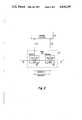
- FIG. 4illustrates the elements of FIG. 1 further providing typical values of signal power loss or gain therethrough.
- a plurality of communications terminalsillustratively including send-only terminals 10 and 12, receive-only terminals 18 and 20, and send/receive terminals 14 and 16, are grouped and coupled via a single cable tap 60 onto communications bus 70 for the purpose of communications.
- Send-only terminals 10 and 12may comprise, for example, radio transmitters, computer keyboards, digital modulators, etc.
- receive-only terminals 18 and 20may comprise, for example, radio receivers, video monitors, printers, digital demodulators, etc.
- send/receive terminals 14 and 16may comprise, for example, radio transceivers, telephones, modems, etc.
- the output signals of send-only terminals 10 and 12 and the transmit output signals of send/receive terminals 14 and 16are combined onto a single signal lead 34 by combiner 30.
- the signal on lead 34is applied to low pass harmonic filter 44 which is selected to pass all fundamental carrier frequencies generated by transmitting terminals 10, 12, 14 and 16.
- the output signal of filter 44is passed via signal lead 46 to combiner/splitter 50, which functions in this case as a combiner, coupling the signal on lead 46 to signal lead 52.
- Combiner/splitter 54which functions in this case as a splitter, receives the signal on lead 52 and couples it to both signal leads 56 and 58.
- the signals carried on leads 56 and 58are coupled to cable tap 60 which is shown, in a preferred embodiment, in FIG. 2.
- Cable tap 60comprises two directional couplers 62 and 64.
- Directional couplersare well known in the art as devices which couple signals traveling in one direction only to a secondary system, while virtually ignoring a signal traveling in the opposite direction.
- the amount of couplingis ordinarily expressed in decibels of attenuation that the signal undergoes in passing through the coupling to the secondary system.
- a directional couplersuch as Model No. PDC-10-1, sold by Mini-Circuits Division of Scientific Components Corp. of Brooklyn, N.Y.
- This modelincludes a plurality of toroidal windings for sensing current and voltage, and operates over a frequency range of 0.5 to 500 MHz.
- a directional coupler of the type described in the aforementioned Apel patentone might select a directional coupler such as Model No. PDC-10-1, sold by Mini-Circuits Division of Scientific Components Corp. of Brooklyn, N.Y.
- This modelincludes a plurality of toroidal windings for sensing current and voltage, and operates over a frequency range of 0.5 to 500 MHz.
- a directional couplerof the type described in the aforementioned Apel patent.
- directional couplers 62 and 64are substantially identical devices, but configured such as to receive oppositely-directed signals transmitted along cable 70. Coupler 62 passes signal along cable 70, the primary transmission system (path 62a), with very little attenuation, typically one-half decibel. Coupler 62 also permits communications between terminals 10 through 20 and terminals whose cable taps are disposed along cable 70 in direction B (toward the left) with relatively small attenuation along path 62b, typically 10 db.
- coupler 62effectively blocks communications between terminals 10 through 20 and terminals whose cable taps are disposed along cable 70 in direction A (toward the right), by exhibiting large attenuation along path 62c (shown as a dashed line), typically 50 db.
- directional coupler 64passes signal along cable 70 (path 64a) with very little attenuation, typically one-half db. Coupler 64 also permits communications between terminals 10 through 20 and terminals whose taps are disposed along cable 70 in direction A with relatively small attenuation along path 64b, typically 10 db. However, coupler 64 effectively blocks communications between terminals 10 through 20 and terminals whose taps are disposed along cable 70 in direction B, by exhibiting large attenuation along path 64c (shown as a dashed line), typically 50 db.
- a signal transmitted along cable 70 in direction Ais received by tap 60 via directional coupler 62 where it passes via signal lead 56 to device 54.
- a signal transmitted along cable 70 in direction Bis received by tap 60 via directional coupler 64 where it passes via signal lead 58 to device 54.
- device 54acts as a combiner, combining the signals on signal leads 56 and 58 onto a single lead 52.
- Device 50acting in this instance as a splitter, receives the combined signal on lead 52 and splits the part received from cable 70 onto signal lead 48 where it is applied to preselector bandpass filter 42, which is selected to pass only a narrow band of carrier frequencies.
- the output signal of filter 42is applied to receive amplifier 38 via lead 40.
- the amplified signalis applied to splitter 32 via signal lead 36.
- Splitter 32couples the signal on lead 36 to the receive portions of send/receive terminals 14 and 16 and to receive-only terminals 18 and 20.
- each of the directional couplers 62 and 64presents a loss of approximately one-half db to signals passing along cable 70.
- the insertion loss of tap 60may be said to be approximately one db.
- a system including the grouping of FIG. 1may illustratively operate within a band of carrier frequencies between 225 and 400 MHz.
- each of the transmitting terminalsi.e., send-only terminals 10 and 12 and the transmit portions of send/receive terminals 14 and 16, are frequency agile, in that they are capable of generating any carrier frequency used within the system.
- Low pass harmonic filter 44passes all signals up to 400 MHz and its response falls off sharply above that frequency to prevent harmonics of the carrier frequencies from entering upon the bus. This is important as the products of harmonics, when intermixed on the bus, may give spurious signals within the system frequency band.
- the receiving terminalsi.e., receive-only terminals 18 and 20 and the receive portions of send/receive terminals 14 and 16 are fixed in frequency. Each is tuned to receive but a single carrier frequency. Further, each receiving terminal within a grouping, those coupled to splitter 32 in the present example, is frequency-tuned within a narrow band of frequencies, e.g., within 2.5 percent of a center frequency. By way of illustration, the receive portions of terminals 14 and 16 and receive-only terminals 18 and 20 may be respectively tuned to four different carrier frequencies within the band of 292.5 to 307.5 MHz, which band comprises frequencies within 2.5 percent of a center frequency of 300 MHz. Each grouping of receivers within a system of the type including the grouping of FIG. 1 is tuned to a different center frequency, and there is no overlap within their respective frequency bands.
- Preselector filter 42is chosen to pass only the narrow band of frequencies to which its associated receivers are tuned. By providing filter 42 with a narrow pass band in this manner, the images of the carrier signals are rejected and, in addition, there can be no leakage of the first local oscillator of each receiver back onto bus 70.
- an intermediate frequency used for all receiversmay typically be 70 MHz.
- Filter 42rejects the image frequency signal at 440 MHz, and additionally blocks the leakage of the 370 MHz local oscillator signal.
- the fixed-frequency grouping of the receivers into a narrow band of frequencieshas a beneficial impact on the selection of receive amplifier 38.
- Amplifiers which are required to provide a linear response only over a narrow frequency bandare readily available and relatively inexpensive, in comparison to broadband amplifiers.
- FIG. 3there is shown a block diagram of a communications system including groups of elements 80 1 , 80 2 , 80 n (designated singly as 80 i ), coupled to bus 70 by taps 60 1 , 60 2 , 60 n (designated singly as 60 i ), respectively, where each group 80 i is of the type shown in FIG. 1 and where each bus tap 60 i is of the type shown in FIGS. 1 and 2.
- Each receiver in the system of FIG. 3is tuned to a different carrier frequency.
- the plurality of receivers within each groupare tuned to carrier frequencies within narrow frequency bands, typically within 2.5 percent of a center frequency, with no overlap between the bands of the several groups 80 i .
- FIG. 4illustrates the grouping of FIG. 1 including typical values of signal power level attenuation and amplification (expressed in decibels) for the several elements of the system.
- Combiner 30provides a loss of 6 db between its four input ports and its output port coupled to lead 34.
- Filter 44provides a loss of 2 db between leads 34 and 46 within its passband.
- Combiner/splitter 50provides a loss of 3 db between leads 46 and 52 and between leads 52 and 48, but it provides a loss of 36 db between leads 46 and 48.
- Combiner/splitter 54provides a loss of 3 db between leads 52 and 56 and between leads 52 and 58.
- Filter 42provides a loss of 6 db between leads 48 and 40 within its passband.
- Amplifier 38provides a gain of 56 db between leads 40 and 36.
- splitter 32provides a loss of 6 db between lead 36 and any of its output ports. The losses through cable tap 60 were enumerated within the earlier discussion relating to FIG. 2.
- the combined loss through devices 30, 44, 50(-36 db path), 42 and 32, is 56 db, which is entirely offset by the 56 db gain in amplifier 38, for a net gain (loss) of 0 db.
- the combined loss through devices 30, 44, 50(-3 db path twice), 54 (twice), 60 (-10 db path twice), 42 and 32, is 52 db. This is offset by the gain through amplifier 38 of 56 db for a net gain of 4 db, which is not substantially different from the 0 db gain demonstrated for the intragroup connection.
- the combined loss through devices 30, 44, 50(-3 db path twice), 54 (twice), 60 (-10 db path twice and the -1 db path six times), 42 and 32, is 58 db. This is offset by the gain through amplifier 38 of 56 db for a net loss of 2 db, which is also not substantially different from the 0 db gain demonstrated for the intragroup connection.
Landscapes
- Engineering & Computer Science (AREA)
- Signal Processing (AREA)
- Cable Transmission Systems, Equalization Of Radio And Reduction Of Echo (AREA)
Abstract
Description
Claims (7)
Priority Applications (1)
| Application Number | Priority Date | Filing Date | Title |
|---|---|---|---|
| US06/697,834US4646295A (en) | 1985-02-04 | 1985-02-04 | Frequency-division multiplex communications system having grouped transmitters and receivers |
Applications Claiming Priority (1)
| Application Number | Priority Date | Filing Date | Title |
|---|---|---|---|
| US06/697,834US4646295A (en) | 1985-02-04 | 1985-02-04 | Frequency-division multiplex communications system having grouped transmitters and receivers |
Publications (1)
| Publication Number | Publication Date |
|---|---|
| US4646295Atrue US4646295A (en) | 1987-02-24 |
Family
ID=24802768
Family Applications (1)
| Application Number | Title | Priority Date | Filing Date |
|---|---|---|---|
| US06/697,834Expired - LifetimeUS4646295A (en) | 1985-02-04 | 1985-02-04 | Frequency-division multiplex communications system having grouped transmitters and receivers |
Country Status (1)
| Country | Link |
|---|---|
| US (1) | US4646295A (en) |
Cited By (15)
| Publication number | Priority date | Publication date | Assignee | Title |
|---|---|---|---|---|
| US4755776A (en)* | 1987-03-06 | 1988-07-05 | Broadband Networks, Inc. | Tap device for broadband communications systems |
| US4955021A (en)* | 1989-07-03 | 1990-09-04 | At&T Bell Laboratories | Efficient connection arrangements for multihop networks |
| US5432838A (en)* | 1990-12-14 | 1995-07-11 | Ainsworth Technologies Inc. | Communication system |
| US5530702A (en)* | 1994-05-31 | 1996-06-25 | Ludwig Kipp | System for storage and communication of information |
| WO1997044914A1 (en)* | 1996-05-20 | 1997-11-27 | Scientific Research Corporation | Pcs cell site system for allowing a plurality of pcs providers to share cell site antennas |
| US5864672A (en)* | 1995-09-12 | 1999-01-26 | At&T Corp. | System for converter for providing downstream second FDM signals over access path and upstream FDM signals sent to central office over the second path |
| USRE36109E (en)* | 1991-04-30 | 1999-02-23 | Kipp; Ludwig | Checkout system |
| US6595811B2 (en)* | 2000-12-19 | 2003-07-22 | Bombardier Inc. | Personal watercraft vehicle component multiplex communication system |
| WO2012116801A1 (en)* | 2011-03-01 | 2012-09-07 | As-International Association E.V. | Bus system having a master and a group of slaves and communication method for interchanging data in such a bus system |
| US20130073760A1 (en)* | 2010-08-19 | 2013-03-21 | Siemens Aktiengesellschaft | As-i communication component |
| US20160258992A1 (en)* | 2015-03-06 | 2016-09-08 | Texas Instruments Incorporated | Wideband Capacitive Sensing Using Sense Signal Modulation |
| US20170271742A1 (en)* | 2016-03-17 | 2017-09-21 | Akg Acoustics Gmbh | Directional coupler and power splitter made therefrom |
| US10050328B2 (en)* | 2015-11-27 | 2018-08-14 | Technetix B.V. | Cable tap |
| US10103420B2 (en) | 2014-07-16 | 2018-10-16 | Technetix B.V. | Cable tap |
| CN113743138A (en)* | 2020-05-28 | 2021-12-03 | 意法半导体奥地利有限公司 | Method for distinguishing between active and passive contactless devices and corresponding reader |
Citations (7)
| Publication number | Priority date | Publication date | Assignee | Title |
|---|---|---|---|---|
| US2421333A (en)* | 1941-04-17 | 1947-05-27 | Int Standard Electric Corp | Multiplex carrier current communication system with transmission line impedance control means |
| US2634334A (en)* | 1948-02-20 | 1953-04-07 | Harry N Kalb | Carrier current communication system |
| US2721897A (en)* | 1951-01-13 | 1955-10-25 | Bell Telephone Labor Inc | Carrier wave communication system |
| US3581209A (en)* | 1968-09-17 | 1971-05-25 | Arie Zimmerman | Cable television program capacity enhancement |
| US3860873A (en)* | 1971-10-01 | 1975-01-14 | Tape Athon Corp | Fm transmission system |
| US4467293A (en)* | 1981-09-18 | 1984-08-21 | Rockwell International Corporation | Ferrite type directional coupler |
| US4481626A (en)* | 1982-05-05 | 1984-11-06 | Xerox Corporation | Transceiver multiplexor |
- 1985
- 1985-02-04USUS06/697,834patent/US4646295A/ennot_activeExpired - Lifetime
Patent Citations (7)
| Publication number | Priority date | Publication date | Assignee | Title |
|---|---|---|---|---|
| US2421333A (en)* | 1941-04-17 | 1947-05-27 | Int Standard Electric Corp | Multiplex carrier current communication system with transmission line impedance control means |
| US2634334A (en)* | 1948-02-20 | 1953-04-07 | Harry N Kalb | Carrier current communication system |
| US2721897A (en)* | 1951-01-13 | 1955-10-25 | Bell Telephone Labor Inc | Carrier wave communication system |
| US3581209A (en)* | 1968-09-17 | 1971-05-25 | Arie Zimmerman | Cable television program capacity enhancement |
| US3860873A (en)* | 1971-10-01 | 1975-01-14 | Tape Athon Corp | Fm transmission system |
| US4467293A (en)* | 1981-09-18 | 1984-08-21 | Rockwell International Corporation | Ferrite type directional coupler |
| US4481626A (en)* | 1982-05-05 | 1984-11-06 | Xerox Corporation | Transceiver multiplexor |
Cited By (21)
| Publication number | Priority date | Publication date | Assignee | Title |
|---|---|---|---|---|
| US4755776A (en)* | 1987-03-06 | 1988-07-05 | Broadband Networks, Inc. | Tap device for broadband communications systems |
| US4955021A (en)* | 1989-07-03 | 1990-09-04 | At&T Bell Laboratories | Efficient connection arrangements for multihop networks |
| US5432838A (en)* | 1990-12-14 | 1995-07-11 | Ainsworth Technologies Inc. | Communication system |
| USRE36109E (en)* | 1991-04-30 | 1999-02-23 | Kipp; Ludwig | Checkout system |
| US5530702A (en)* | 1994-05-31 | 1996-06-25 | Ludwig Kipp | System for storage and communication of information |
| US5864672A (en)* | 1995-09-12 | 1999-01-26 | At&T Corp. | System for converter for providing downstream second FDM signals over access path and upstream FDM signals sent to central office over the second path |
| WO1997044914A1 (en)* | 1996-05-20 | 1997-11-27 | Scientific Research Corporation | Pcs cell site system for allowing a plurality of pcs providers to share cell site antennas |
| US5781865A (en)* | 1996-05-20 | 1998-07-14 | Scientific Research Corporation | PCS cell site system for allowing a plurality of PCS providers to share cell site antennas |
| US6595811B2 (en)* | 2000-12-19 | 2003-07-22 | Bombardier Inc. | Personal watercraft vehicle component multiplex communication system |
| US20130073760A1 (en)* | 2010-08-19 | 2013-03-21 | Siemens Aktiengesellschaft | As-i communication component |
| WO2012116801A1 (en)* | 2011-03-01 | 2012-09-07 | As-International Association E.V. | Bus system having a master and a group of slaves and communication method for interchanging data in such a bus system |
| US20140025854A1 (en)* | 2011-03-01 | 2014-01-23 | As-International Association E.V. | Bus system having a master and a group of slaves and communication method for interchanging data in said bus system |
| JP2014508477A (en)* | 2011-03-01 | 2014-04-03 | アス−インターナショナル アソシエーション エーヴェー | Bus system having master and group of slaves and communication system for exchanging data of said bus system |
| US9507661B2 (en)* | 2011-03-01 | 2016-11-29 | As-International Association E.V. | Bus system having a master and a group of slaves and communication method for interchanging data in said bus system |
| US10103420B2 (en) | 2014-07-16 | 2018-10-16 | Technetix B.V. | Cable tap |
| US20160258992A1 (en)* | 2015-03-06 | 2016-09-08 | Texas Instruments Incorporated | Wideband Capacitive Sensing Using Sense Signal Modulation |
| US10050328B2 (en)* | 2015-11-27 | 2018-08-14 | Technetix B.V. | Cable tap |
| US20170271742A1 (en)* | 2016-03-17 | 2017-09-21 | Akg Acoustics Gmbh | Directional coupler and power splitter made therefrom |
| CN113743138A (en)* | 2020-05-28 | 2021-12-03 | 意法半导体奥地利有限公司 | Method for distinguishing between active and passive contactless devices and corresponding reader |
| US11416692B2 (en)* | 2020-05-28 | 2022-08-16 | STMicroelectronics Austria GmbH | Method for distinguishing between active and passive contactless devices, and corresponding reader |
| CN113743138B (en)* | 2020-05-28 | 2024-05-07 | 意法半导体奥地利有限公司 | Method for distinguishing active and passive contactless devices and corresponding readers |
Similar Documents
| Publication | Publication Date | Title |
|---|---|---|
| US4646295A (en) | Frequency-division multiplex communications system having grouped transmitters and receivers | |
| US3886454A (en) | Control apparatus for a two-way cable television system | |
| US4644526A (en) | Full duplex frequency division multiplex communication system | |
| US5424864A (en) | Microcellular mobile communication system | |
| US4512025A (en) | Increasing capacity of baseband digital data communication networks | |
| CA2061041C (en) | Optical communications systems for the subscriber area with optical amplifiers | |
| US5634191A (en) | Self-adjusting RF repeater arrangements for wireless telephone systems | |
| AU602064B2 (en) | A low power multi-function cellular television system | |
| US4521881A (en) | Data communication system with increased effective bandwidth | |
| JP2520530B2 (en) | Microcell communication station, method of radio signal processing in microcell communication station, microcellular communication system, and cellular communication base station | |
| US4667319A (en) | Digital repeater with 3-way branching of service channels | |
| US4107471A (en) | Frequency division multiplex communications system | |
| JPH09200840A (en) | Private wireless communication system | |
| GB1236776A (en) | Television telephone system | |
| US6513163B1 (en) | Embedded forward reference and control | |
| US3636452A (en) | Radio relay system | |
| CA2232615A1 (en) | Dual transmitter arrangement with back-up switching | |
| US4236244A (en) | Digital communications transmission system | |
| CA2069462A1 (en) | Rf repeater arrangement with reduced noise for wireless telephones | |
| US3022504A (en) | Two-way radio telephone system utilizing frequency subbands to provide transmitter-receiver isolation | |
| US2802056A (en) | Multiplex system | |
| US1658337A (en) | Carrier-wave signaling system | |
| RU2101868C1 (en) | Information transmission device | |
| US7062252B2 (en) | Capacity optimization of a wired cellular network | |
| US4852087A (en) | Receiver data gate with automatic gain control |
Legal Events
| Date | Code | Title | Description |
|---|---|---|---|
| AS | Assignment | Owner name:RCA CORPORATION A CORP OF DEL Free format text:ASSIGNMENT OF ASSIGNORS INTEREST.;ASSIGNOR:BASILE, PHILIP C.;REEL/FRAME:004371/0323 Effective date:19850130 | |
| STCF | Information on status: patent grant | Free format text:PATENTED CASE | |
| FPAY | Fee payment | Year of fee payment:4 | |
| FPAY | Fee payment | Year of fee payment:8 | |
| AS | Assignment | Owner name:MARTIN MARIETTA CORPORATION, MARYLAND Free format text:ASSIGNMENT OF ASSIGNORS INTEREST;ASSIGNOR:GENERAL ELECTRIC COMPANY;REEL/FRAME:007046/0736 Effective date:19940322 | |
| AS | Assignment | Owner name:LOCKHEED MARTIN CORPORATION, MARYLAND Free format text:ASSIGNMENT OF ASSIGNORS INTEREST;ASSIGNOR:MARTIN MARIETTA CORPORATION;REEL/FRAME:008628/0518 Effective date:19960128 | |
| FPAY | Fee payment | Year of fee payment:12 | |
| AS | Assignment | Owner name:L-3 COMMUNICATIONS CORPORATION, NEW YORK Free format text:ASSIGNMENT OF ASSIGNORS INTEREST;ASSIGNOR:LOCKHEED MARTIN CORPORATION, A CORP. OF MD;REEL/FRAME:010180/0073 Effective date:19970430 |