US4645320A - Camera mount for motor vehicle - Google Patents
Camera mount for motor vehicleDownload PDFInfo
- Publication number
- US4645320A US4645320AUS06/811,452US81145285AUS4645320AUS 4645320 AUS4645320 AUS 4645320AUS 81145285 AUS81145285 AUS 81145285AUS 4645320 AUS4645320 AUS 4645320A
- Authority
- US
- United States
- Prior art keywords
- pendulum
- vehicle
- camera
- mass
- sprung mass
- Prior art date
- Legal status (The legal status is an assumption and is not a legal conclusion. Google has not performed a legal analysis and makes no representation as to the accuracy of the status listed.)
- Expired - Fee Related
Links
- 238000013016dampingMethods0.000claimsabstractdescription21
- 239000000725suspensionSubstances0.000claimsabstractdescription10
- 230000001133accelerationEffects0.000claimsdescription19
- 230000005484gravityEffects0.000claimsdescription2
- 230000033001locomotionEffects0.000description3
- 230000000007visual effectEffects0.000description3
- 238000000034methodMethods0.000description2
- 239000011435rockSubstances0.000description2
- 230000000694effectsEffects0.000description1
Images

Classifications
- F—MECHANICAL ENGINEERING; LIGHTING; HEATING; WEAPONS; BLASTING
- F16—ENGINEERING ELEMENTS AND UNITS; GENERAL MEASURES FOR PRODUCING AND MAINTAINING EFFECTIVE FUNCTIONING OF MACHINES OR INSTALLATIONS; THERMAL INSULATION IN GENERAL
- F16M—FRAMES, CASINGS OR BEDS OF ENGINES, MACHINES OR APPARATUS, NOT SPECIFIC TO ENGINES, MACHINES OR APPARATUS PROVIDED FOR ELSEWHERE; STANDS; SUPPORTS
- F16M11/00—Stands or trestles as supports for apparatus or articles placed thereon ; Stands for scientific apparatus such as gravitational force meters
- F16M11/02—Heads
- F16M11/18—Heads with mechanism for moving the apparatus relatively to the stand
- B—PERFORMING OPERATIONS; TRANSPORTING
- B60—VEHICLES IN GENERAL
- B60R—VEHICLES, VEHICLE FITTINGS, OR VEHICLE PARTS, NOT OTHERWISE PROVIDED FOR
- B60R11/00—Arrangements for holding or mounting articles, not otherwise provided for
- B60R11/04—Mounting of cameras operative during drive; Arrangement of controls thereof relative to the vehicle
- F—MECHANICAL ENGINEERING; LIGHTING; HEATING; WEAPONS; BLASTING
- F16—ENGINEERING ELEMENTS AND UNITS; GENERAL MEASURES FOR PRODUCING AND MAINTAINING EFFECTIVE FUNCTIONING OF MACHINES OR INSTALLATIONS; THERMAL INSULATION IN GENERAL
- F16M—FRAMES, CASINGS OR BEDS OF ENGINES, MACHINES OR APPARATUS, NOT SPECIFIC TO ENGINES, MACHINES OR APPARATUS PROVIDED FOR ELSEWHERE; STANDS; SUPPORTS
- F16M11/00—Stands or trestles as supports for apparatus or articles placed thereon ; Stands for scientific apparatus such as gravitational force meters
- F16M11/02—Heads
- F16M11/04—Means for attachment of apparatus; Means allowing adjustment of the apparatus relatively to the stand
- F16M11/06—Means for attachment of apparatus; Means allowing adjustment of the apparatus relatively to the stand allowing pivoting
- F16M11/12—Means for attachment of apparatus; Means allowing adjustment of the apparatus relatively to the stand allowing pivoting in more than one direction
- F16M11/121—Means for attachment of apparatus; Means allowing adjustment of the apparatus relatively to the stand allowing pivoting in more than one direction constituted of several dependent joints
- F16M11/123—Means for attachment of apparatus; Means allowing adjustment of the apparatus relatively to the stand allowing pivoting in more than one direction constituted of several dependent joints the axis of rotation intersecting in a single point, e.g. by using gimbals
- G—PHYSICS
- G03—PHOTOGRAPHY; CINEMATOGRAPHY; ANALOGOUS TECHNIQUES USING WAVES OTHER THAN OPTICAL WAVES; ELECTROGRAPHY; HOLOGRAPHY
- G03B—APPARATUS OR ARRANGEMENTS FOR TAKING PHOTOGRAPHS OR FOR PROJECTING OR VIEWING THEM; APPARATUS OR ARRANGEMENTS EMPLOYING ANALOGOUS TECHNIQUES USING WAVES OTHER THAN OPTICAL WAVES; ACCESSORIES THEREFOR
- G03B29/00—Combinations of cameras, projectors or photographic printing apparatus with non-photographic non-optical apparatus, e.g. clocks or weapons; Cameras having the shape of other objects
- F—MECHANICAL ENGINEERING; LIGHTING; HEATING; WEAPONS; BLASTING
- F16—ENGINEERING ELEMENTS AND UNITS; GENERAL MEASURES FOR PRODUCING AND MAINTAINING EFFECTIVE FUNCTIONING OF MACHINES OR INSTALLATIONS; THERMAL INSULATION IN GENERAL
- F16M—FRAMES, CASINGS OR BEDS OF ENGINES, MACHINES OR APPARATUS, NOT SPECIFIC TO ENGINES, MACHINES OR APPARATUS PROVIDED FOR ELSEWHERE; STANDS; SUPPORTS
- F16M2200/00—Details of stands or supports
- F16M2200/04—Balancing means
- F16M2200/044—Balancing means for balancing rotational movement of the undercarriage
Definitions
- This inventionrelates to a mount for a camera in a vehicle which allows a moving picture to be taken through a window of the vehicle to show the exterior surroundings as they would be seen by a vehicle passenger. It has been observed that vehicle passengers tend to generally maintain their visual attitude oriented level to the apparent horizon. When a vehicle on level ground is subjected to horizontal accelerations such as cornering or braking, an occupant will lean his torso and/or head to maintain his level visual orientation. Moreover, when the vehicle is going uphill or downhill, the occupant tends to allow his body to rotate with the vehicle only sufficiently to maintain a visual orientation level relative to the horizon. A camera mount for a realistic moving picture of a vehicle occupant's view must operate in the same manner.
- One prior art method of mounting a camera in a vehicleprovides a platform fixed to the vehicle sprung mass. This mount, however, restrains the camera to rotate with the vehicle sprung mass at all times. Thus, through vehicle accelerations such as cornering and braking, the camera will tilt with respect to the road surface. On hills, the camera will over-rotate with the vehicle sprung mass due to gravitationally produced rotation and thus tilt forward or backward with respect to the road surface. In both cases the camera will produce a moving picture unrealistic in appearance, since it does not correspond to the behavior of most vehicle occupants during such maneuvers.
- the camera mount of the inventionis adapted for a motor vehicle of the type having an unsprung mass with supporting wheels and a sprung mass, the unsprung mass being supported by the wheels on a road surface and the sprung mass being supported on the unsprung mass by a suspension system comprising vehicle spring elements and vehicle damping elements allowing relative rotation of the vehicle sprung mass relative to the unsprung mass due to accelerational and gravitational forces.
- the camera mountcomprises a supporting frame rigidly supported within the motor vehicle sprung mass, a gimbal support on the supporting frame and a pendulum suspended from the gimbal support, the pendulum including camera support means and having a steady state position on a horizontal road surface in the absence of vehicle acceleration defining a level camera attitude with respect to the sprung mass and the unsprung mass.
- Pendulum spring elementsare effective to exert a restoring force when the pendulum rotates from its steady state position with respect to the vehicle sprung mass; and pendulum damping elements are effective to exert a damping force during pendulum rotation relative to the vehicle sprung mass.
- the pendulum spring elements and pendulum damping elementshave spring and damping coefficients, respectively, of magnitude matched to those of the vehicle suspension system. Thus they are effective during rotations of the sprung mass relative to the unsprung mass due to accelerational or gravitational forces to allow rotation of the pendulum through an equal and opposite angle, whereby the camera is maintained level with respect to the road surface regardless of vehicle accelerations due to cornering, stopping and increasing velocity or grade changes in the road surface from the horizontal. Further details and advantages of this invention will be apparent from the accompanying drawings and following description of a preferred embodiment.
- FIG. 1is a perspective view of a preferred embodiment of a camera mount according to this invention.
- FIG. 2is a front elevational view of the camera mount structure of the embodiment of FIG. 1 simplified to show the weight balancing thereof.
- FIG. 3is an elevational view taken along lines 3--3 of FIG. 2.
- FIG. 4is an elevational view taken along lines 4--4 of FIG. 3.
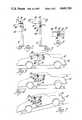
- FIGS. 5-7are side schematic views of a simplified version of the embodiment of FIG. 1 mounted in a vehicle which is, respectively, level and unaccelerated, level and accelerated, and unlevel and unaccelerated.
- a motor vehicle 10has an unsprung mass including wheels 11 and a sprung mass including a body 12.
- the sprung and unsprung massesare joined in a standard suspension system, not shown, including springs and damping elements at each of the wheels 11, which suspension system allows the sprung mass to rotate about horizontal axes with respect to the unsprung mass when subjected to strong horizontal accelerations.
- An exaggerated view of an accelerated vehicleis shown in FIG. 6, the particular acceleration being an increase in vehicle velocity with the body 12 rocking backward in rotation relative to wheels 11 and the road surface.
- the suspension systemwill, however, allow such rotation about any horizontal axis to allow components of sideways rocking as well as fore and aft rocking and combinations thereof.
- FIG. 7shows the same vehicle proceeding uphill with no acceleration.
- the springs of the suspension systemallow some rotation of the sprung mass relative to the unsprung mass due to gravitational force; and the vehicle body 12 rocks back slightly with respect to the wheels 11 and road surface. If the vehicle were proceeding downhill, the vehicle body 12 would rock slightly forward with respect to the wheels 11 and road surface. Accelerations will produce rocking similar to that shown in FIG. 6 in the forward, backward or sideways direction relative to the position caused by the angle of the road surface.
- Such responsesare familiar to anyone who has been in a motor vehicle operated on the public roads.
- a frame 13comprises horizontal octagonal frame member 15, angular frame members 16, 17 and 18, and braces 20 and 21.
- Frame members 16 and 17are fixed at their lower ends to frame member 15 and at their upper ends to mounting stud 22, by which the frame 13 is fixedly mounted within the passenger compartment of a motor vehicle.
- One U-shaped member 23 of a universal joint type gimbal mount 25is clamped onto stud 22 and braced by the upper end of frame member 18.
- Another U-shaped member 26 of gimbal mount 25is suspended from the X-shaped cross shaft 27 thereof so as to swing freely below it.
- a block 28 clamped onto the lower end of U-shaped member 26extends sideways to support a vertical tube 30 having a pendulum weight 31 at its lower end and an adjustable camera mounting apparatus 32 at its upper end.
- a camera 33is shown as a box with broken lines in mounted position on mounting plate 32. The camera lens 35 faces to the front right in the Figure, parallel to the stud 22.
- Tube 30is horizontally offset to one side along a first axis from the rotational center of the gimbal mount 25 and the camera is likewise horizontally offset to the back along a second axis from the rotational center of the gimbal mount 25. Therefore, the pendulum weight is horizontally offset by appropriate amounts in the opposite directions, to the other side along the first axis and to the front along the second axis. This places the components of the center of gravity of weight 31 along the first and second axes directly under the gimbal mount so that the tube naturally tends to hang truly vertically downward in the absence of horizontal accelerations.
- FIGS. 2-4wherein the pivot point of the gimbal apparatus is marked by the reference numeral 36.
- a collar 37 on tube 30 between block 28 and pendulum weight 31provides attachment for four coil springs 38 extending horizontally in tension in four directions--to the front, back, left and right--outwardly to adjustment screws 40 in mounting flanges 41 attached to frame member 15.
- These springs 38provide a restoring force, adjustable by varying the length thereof with adjustment screws 40, which resists rotation of the pendulum comprising weight 31 and tube 30 in any direction away from a steady state position in which tube 30 is perpendicular to the plane of frame member 15.
- Damping members 42 connecting flanges 43 fixed to frame member 15 and collar 45 on tube 30provide damping resistance to movement of the aforementioned pendulum.
- Flanges 43are braced by braces 20 and 21.
- Damping members 42are adjustable and extend orthogonally to each other, longitudinally and sideways relative to the vehicle body 12 and thus parallel to two of the springs 38.
- Springs 38 and damping members 42are adjusted to provide spring and damping coefficients for the pendulum matched to the spring and damping coefficients of the vehicle suspension system under horizontal accelerations.
- the springs 38 and damping members 42will allow an equal and opposite rotation of the pendulum weight 31 to maintain the preacceleration attitude of the camera. If the vehicle had been on a level horizontal surface before the acceleration so the camera was pointed at the horizon, the camera will remain pointed at the horizon through the acceleration.
Landscapes
- Engineering & Computer Science (AREA)
- General Engineering & Computer Science (AREA)
- Mechanical Engineering (AREA)
- Physics & Mathematics (AREA)
- General Physics & Mathematics (AREA)
- Accessories Of Cameras (AREA)
Abstract
Description
Claims (3)
Priority Applications (1)
| Application Number | Priority Date | Filing Date | Title |
|---|---|---|---|
| US06/811,452US4645320A (en) | 1985-12-20 | 1985-12-20 | Camera mount for motor vehicle |
Applications Claiming Priority (1)
| Application Number | Priority Date | Filing Date | Title |
|---|---|---|---|
| US06/811,452US4645320A (en) | 1985-12-20 | 1985-12-20 | Camera mount for motor vehicle |
Publications (1)
| Publication Number | Publication Date |
|---|---|
| US4645320Atrue US4645320A (en) | 1987-02-24 |
Family
ID=25206584
Family Applications (1)
| Application Number | Title | Priority Date | Filing Date |
|---|---|---|---|
| US06/811,452Expired - Fee RelatedUS4645320A (en) | 1985-12-20 | 1985-12-20 | Camera mount for motor vehicle |
Country Status (1)
| Country | Link |
|---|---|
| US (1) | US4645320A (en) |
Cited By (44)
| Publication number | Priority date | Publication date | Assignee | Title |
|---|---|---|---|---|
| US5184521A (en)* | 1991-11-18 | 1993-02-09 | Nelson Tyler | Gyroscopically stabilized apparatus |
| US5833101A (en)* | 1997-08-28 | 1998-11-10 | Watkins; D. Scott | Camera mount |
| US6116485A (en)* | 1997-08-28 | 2000-09-12 | Watkins; D. Scott | Camera mount |
| US6198502B1 (en) | 1998-07-22 | 2001-03-06 | D. Scott Watkins | Headrest and seat video imaging apparatus |
| US6201568B1 (en) | 1998-07-22 | 2001-03-13 | D. Scott Watkins | Headrest video camera |
| US6215518B1 (en) | 1998-07-22 | 2001-04-10 | D. Scott Watkins | Headrest and seat video imaging apparatus |
| US6315180B1 (en) | 1997-08-28 | 2001-11-13 | D. Scott Watkins | Camera mount |
| US6445408B1 (en) | 1998-07-22 | 2002-09-03 | D. Scott Watkins | Headrest and seat video imaging apparatus |
| US20020131781A1 (en)* | 2001-02-14 | 2002-09-19 | Buck John S. | Self-leveling camera |
| US6524020B2 (en)* | 2000-09-22 | 2003-02-25 | Dr. Ing. H.C.F. Porsche Aktiengesellschaft | Camera built into a motor vehicle |
| US6547205B2 (en)* | 2001-04-27 | 2003-04-15 | Engineered Support Systems, Inc. | Isolation platform assembly for supporting an instrumentation payload |
| US20040034452A1 (en)* | 2002-08-19 | 2004-02-19 | Miller Ronald Hugh | Steerable night vision system |
| US20050031335A1 (en)* | 2003-08-05 | 2005-02-10 | Arnold Itzkowitz | Frame assembly for supporting a camera |
| US20050196163A1 (en)* | 2004-03-03 | 2005-09-08 | Mootz Jeffery S. | Self Leveling Camera Support Apparatus |
| US20050196162A1 (en)* | 2004-03-03 | 2005-09-08 | Mootz Jeffery S. | Self Leveling Camera Support Apparatus |
| US20050231634A1 (en)* | 2004-04-16 | 2005-10-20 | Chapman/Leonard Studio Equipment | Shock and vibration isolator for a camera |
| US20050232625A1 (en)* | 2004-04-16 | 2005-10-20 | Chapman/Leonard Studio Equipment | Shock and vibration isolator for a camera |
| US20060239678A1 (en)* | 2004-08-02 | 2006-10-26 | Arnold Itzkowitz | Stable platform for image capturing |
| US20070108712A1 (en)* | 2005-08-23 | 2007-05-17 | Jeff Ryan | Shock isolation cradle |
| RU2364529C1 (en)* | 2008-08-26 | 2009-08-20 | Айрат Талгатович Ситдиков | Device to attach video camera inside passenger compartment |
| US20090230709A1 (en)* | 2008-03-13 | 2009-09-17 | Michael Lawrence Beauchamp | Home utility management vehicle mini van or Hum V Mini Van |
| WO2009152446A1 (en)* | 2008-06-12 | 2009-12-17 | Milestone Av Technologies Llc | Universal projector interface with sustainable alignment |
| US20120169876A1 (en)* | 2009-08-28 | 2012-07-05 | Riegl Laser Measurement Systems Gmbh | Laser scanning device for mounting on the roof rack of a vehicle |
| US20120217718A1 (en)* | 2011-02-24 | 2012-08-30 | Chapman/Leonard Studio Equipment, Inc. | Camera car |
| USD687879S1 (en) | 2012-11-21 | 2013-08-13 | Nitroworks Corporation | Camera mount for supporting two cameras |
| USD687878S1 (en) | 2012-11-21 | 2013-08-13 | Nitroworks Corporation | Camera mount |
| USD709547S1 (en) | 2012-11-21 | 2014-07-22 | Nitroworks Corporation | Base for a camera mount |
| US8831415B2 (en) | 2012-07-12 | 2014-09-09 | Nitroworks Corporation | Rotating camera mount with counterweight |
| US8993951B2 (en) | 1996-03-25 | 2015-03-31 | Magna Electronics Inc. | Driver assistance system for a vehicle |
| WO2015095951A1 (en) | 2013-12-24 | 2015-07-02 | Pv Labs Inc. | Platform stabilization system |
| US9171217B2 (en) | 2002-05-03 | 2015-10-27 | Magna Electronics Inc. | Vision system for vehicle |
| US9191634B2 (en) | 2004-04-15 | 2015-11-17 | Magna Electronics Inc. | Vision system for vehicle |
| US9201292B1 (en) | 2015-02-13 | 2015-12-01 | Michael Nevin Folgarelli | Camera motion damping |
| US9436880B2 (en) | 1999-08-12 | 2016-09-06 | Magna Electronics Inc. | Vehicle vision system |
| US9440535B2 (en) | 2006-08-11 | 2016-09-13 | Magna Electronics Inc. | Vision system for vehicle |
| US9450286B1 (en)* | 2012-09-12 | 2016-09-20 | Viasat, Inc. | Systems, devices, and methods for stabilizing an antenna |
| US9762779B2 (en) | 2014-10-10 | 2017-09-12 | Dotworkz | Shock-resistant camera mounting device and methods of forming the same |
| WO2018170882A1 (en)* | 2017-03-24 | 2018-09-27 | Sz Dji Osmo Technology Co., Ltd. | Method and system for adaptive gimbal |
| US10283837B2 (en) | 2015-10-23 | 2019-05-07 | Viasat, Inc. | Apparatuses for mounting an antenna assembly |
| US11009180B2 (en) | 2018-10-05 | 2021-05-18 | Joergen Geerds | Camera mount |
| CN113060077A (en)* | 2021-03-12 | 2021-07-02 | 深圳市乐其网络科技有限公司 | Shock absorption support and shock absorption device of shooting equipment |
| US11134201B2 (en)* | 2019-08-20 | 2021-09-28 | International Business Machines Corporation | Vision assisted driving system using a vertically extendable camera |
| US20230023116A1 (en)* | 2019-12-23 | 2023-01-26 | Cnh Industrial America Llc | Reel assembly with retractable sensor arm for an agricultural header |
| US20230025352A1 (en)* | 2019-12-23 | 2023-01-26 | Cnh Industrial America Llc | Reel assembly with retractable sensor arm for an agricultural header |
Citations (9)
| Publication number | Priority date | Publication date | Assignee | Title |
|---|---|---|---|---|
| US1824085A (en)* | 1930-06-12 | 1931-09-22 | James C Karnes | Camera mounting |
| US2506095A (en)* | 1948-04-13 | 1950-05-02 | Mantz Albert Paul | Vibration-damping camera mount |
| US3094054A (en)* | 1957-10-29 | 1963-06-18 | Hycon Mfg Company | Camera stabilized mount |
| US3176308A (en)* | 1960-09-19 | 1965-03-30 | Aero Service Corp | Continuous photographic apparatus |
| US3380310A (en)* | 1964-06-02 | 1968-04-30 | Gen Dynamies Corp | Stabilization system |
| US3515472A (en)* | 1967-11-14 | 1970-06-02 | Ralph K Schwitzgebel | Vehicle camera systems |
| US3523660A (en)* | 1968-02-05 | 1970-08-11 | Condor Helicopters & Aviat Inc | Television camera mounting structure for helicopters used in aerial survey work |
| US3638502A (en)* | 1969-12-01 | 1972-02-01 | Westinghouse Canada Ltd | Stabilized camera mount |
| US4093364A (en)* | 1977-02-04 | 1978-06-06 | Miller Keith G | Dual path photographic camera for use in motor vehicles |
- 1985
- 1985-12-20USUS06/811,452patent/US4645320A/ennot_activeExpired - Fee Related
Patent Citations (9)
| Publication number | Priority date | Publication date | Assignee | Title |
|---|---|---|---|---|
| US1824085A (en)* | 1930-06-12 | 1931-09-22 | James C Karnes | Camera mounting |
| US2506095A (en)* | 1948-04-13 | 1950-05-02 | Mantz Albert Paul | Vibration-damping camera mount |
| US3094054A (en)* | 1957-10-29 | 1963-06-18 | Hycon Mfg Company | Camera stabilized mount |
| US3176308A (en)* | 1960-09-19 | 1965-03-30 | Aero Service Corp | Continuous photographic apparatus |
| US3380310A (en)* | 1964-06-02 | 1968-04-30 | Gen Dynamies Corp | Stabilization system |
| US3515472A (en)* | 1967-11-14 | 1970-06-02 | Ralph K Schwitzgebel | Vehicle camera systems |
| US3523660A (en)* | 1968-02-05 | 1970-08-11 | Condor Helicopters & Aviat Inc | Television camera mounting structure for helicopters used in aerial survey work |
| US3638502A (en)* | 1969-12-01 | 1972-02-01 | Westinghouse Canada Ltd | Stabilized camera mount |
| US4093364A (en)* | 1977-02-04 | 1978-06-06 | Miller Keith G | Dual path photographic camera for use in motor vehicles |
Cited By (89)
| Publication number | Priority date | Publication date | Assignee | Title |
|---|---|---|---|---|
| US5184521A (en)* | 1991-11-18 | 1993-02-09 | Nelson Tyler | Gyroscopically stabilized apparatus |
| US8993951B2 (en) | 1996-03-25 | 2015-03-31 | Magna Electronics Inc. | Driver assistance system for a vehicle |
| US5833101A (en)* | 1997-08-28 | 1998-11-10 | Watkins; D. Scott | Camera mount |
| US6116485A (en)* | 1997-08-28 | 2000-09-12 | Watkins; D. Scott | Camera mount |
| US6315180B1 (en) | 1997-08-28 | 2001-11-13 | D. Scott Watkins | Camera mount |
| US6198502B1 (en) | 1998-07-22 | 2001-03-06 | D. Scott Watkins | Headrest and seat video imaging apparatus |
| US6201568B1 (en) | 1998-07-22 | 2001-03-13 | D. Scott Watkins | Headrest video camera |
| US6215518B1 (en) | 1998-07-22 | 2001-04-10 | D. Scott Watkins | Headrest and seat video imaging apparatus |
| US6445408B1 (en) | 1998-07-22 | 2002-09-03 | D. Scott Watkins | Headrest and seat video imaging apparatus |
| US9436880B2 (en) | 1999-08-12 | 2016-09-06 | Magna Electronics Inc. | Vehicle vision system |
| US6524020B2 (en)* | 2000-09-22 | 2003-02-25 | Dr. Ing. H.C.F. Porsche Aktiengesellschaft | Camera built into a motor vehicle |
| US20020131781A1 (en)* | 2001-02-14 | 2002-09-19 | Buck John S. | Self-leveling camera |
| US6611661B2 (en)* | 2001-02-14 | 2003-08-26 | Clean Line Incorporated | Self-leveling camera |
| US6547205B2 (en)* | 2001-04-27 | 2003-04-15 | Engineered Support Systems, Inc. | Isolation platform assembly for supporting an instrumentation payload |
| WO2002088585A3 (en)* | 2001-04-27 | 2004-03-11 | Engineered Support Systems Inc | Isolation platform assembly for supporting an instrumentation payload |
| US9555803B2 (en) | 2002-05-03 | 2017-01-31 | Magna Electronics Inc. | Driver assistance system for vehicle |
| US9171217B2 (en) | 2002-05-03 | 2015-10-27 | Magna Electronics Inc. | Vision system for vehicle |
| US9643605B2 (en) | 2002-05-03 | 2017-05-09 | Magna Electronics Inc. | Vision system for vehicle |
| US11203340B2 (en) | 2002-05-03 | 2021-12-21 | Magna Electronics Inc. | Vehicular vision system using side-viewing camera |
| US10683008B2 (en) | 2002-05-03 | 2020-06-16 | Magna Electronics Inc. | Vehicular driving assist system using forward-viewing camera |
| US9834216B2 (en) | 2002-05-03 | 2017-12-05 | Magna Electronics Inc. | Vehicular control system using cameras and radar sensor |
| US10118618B2 (en) | 2002-05-03 | 2018-11-06 | Magna Electronics Inc. | Vehicular control system using cameras and radar sensor |
| US10351135B2 (en) | 2002-05-03 | 2019-07-16 | Magna Electronics Inc. | Vehicular control system using cameras and radar sensor |
| US6725139B2 (en) | 2002-08-19 | 2004-04-20 | Ford Global Technologies, Llc | Steerable night vision system |
| US20040034452A1 (en)* | 2002-08-19 | 2004-02-19 | Miller Ronald Hugh | Steerable night vision system |
| US7068927B2 (en) | 2003-08-05 | 2006-06-27 | Arnold Itzkowitz | Frame assembly for supporting a camera |
| US20050031335A1 (en)* | 2003-08-05 | 2005-02-10 | Arnold Itzkowitz | Frame assembly for supporting a camera |
| US7090416B2 (en) | 2004-03-03 | 2006-08-15 | Jeffery Scott Mootz | Self leveling camera support apparatus |
| US7241060B2 (en) | 2004-03-03 | 2007-07-10 | Jeffery Scott Mootz | Self leveling camera support apparatus |
| US20050196162A1 (en)* | 2004-03-03 | 2005-09-08 | Mootz Jeffery S. | Self Leveling Camera Support Apparatus |
| US20050196163A1 (en)* | 2004-03-03 | 2005-09-08 | Mootz Jeffery S. | Self Leveling Camera Support Apparatus |
| US10187615B1 (en) | 2004-04-15 | 2019-01-22 | Magna Electronics Inc. | Vehicular control system |
| US10306190B1 (en) | 2004-04-15 | 2019-05-28 | Magna Electronics Inc. | Vehicular control system |
| US11847836B2 (en) | 2004-04-15 | 2023-12-19 | Magna Electronics Inc. | Vehicular control system with road curvature determination |
| US11503253B2 (en) | 2004-04-15 | 2022-11-15 | Magna Electronics Inc. | Vehicular control system with traffic lane detection |
| US9191634B2 (en) | 2004-04-15 | 2015-11-17 | Magna Electronics Inc. | Vision system for vehicle |
| US10735695B2 (en) | 2004-04-15 | 2020-08-04 | Magna Electronics Inc. | Vehicular control system with traffic lane detection |
| US9948904B2 (en) | 2004-04-15 | 2018-04-17 | Magna Electronics Inc. | Vision system for vehicle |
| US10462426B2 (en) | 2004-04-15 | 2019-10-29 | Magna Electronics Inc. | Vehicular control system |
| US9609289B2 (en) | 2004-04-15 | 2017-03-28 | Magna Electronics Inc. | Vision system for vehicle |
| US9428192B2 (en) | 2004-04-15 | 2016-08-30 | Magna Electronics Inc. | Vision system for vehicle |
| US10015452B1 (en) | 2004-04-15 | 2018-07-03 | Magna Electronics Inc. | Vehicular control system |
| US9736435B2 (en) | 2004-04-15 | 2017-08-15 | Magna Electronics Inc. | Vision system for vehicle |
| US10110860B1 (en) | 2004-04-15 | 2018-10-23 | Magna Electronics Inc. | Vehicular control system |
| US7137747B2 (en)* | 2004-04-16 | 2006-11-21 | Chapman/Leonard Studio Equipment | Shock and vibration isolator for a camera |
| US20050232625A1 (en)* | 2004-04-16 | 2005-10-20 | Chapman/Leonard Studio Equipment | Shock and vibration isolator for a camera |
| US20050231634A1 (en)* | 2004-04-16 | 2005-10-20 | Chapman/Leonard Studio Equipment | Shock and vibration isolator for a camera |
| US7522213B2 (en) | 2004-04-16 | 2009-04-21 | Chapman/Leonard Studio Equipment | Shock and vibration isolator for a camera |
| US7303341B2 (en) | 2004-08-02 | 2007-12-04 | Arnold Itzkowitz | Stable platform for image capturing |
| US20060239678A1 (en)* | 2004-08-02 | 2006-10-26 | Arnold Itzkowitz | Stable platform for image capturing |
| US20070108712A1 (en)* | 2005-08-23 | 2007-05-17 | Jeff Ryan | Shock isolation cradle |
| US7513516B2 (en) | 2005-08-23 | 2009-04-07 | Jri Development Group, Llc | Shock isolation cradle |
| US10787116B2 (en) | 2006-08-11 | 2020-09-29 | Magna Electronics Inc. | Adaptive forward lighting system for vehicle comprising a control that adjusts the headlamp beam in response to processing of image data captured by a camera |
| US10071676B2 (en) | 2006-08-11 | 2018-09-11 | Magna Electronics Inc. | Vision system for vehicle |
| US9440535B2 (en) | 2006-08-11 | 2016-09-13 | Magna Electronics Inc. | Vision system for vehicle |
| US11148583B2 (en) | 2006-08-11 | 2021-10-19 | Magna Electronics Inc. | Vehicular forward viewing image capture system |
| US11951900B2 (en) | 2006-08-11 | 2024-04-09 | Magna Electronics Inc. | Vehicular forward viewing image capture system |
| US11396257B2 (en) | 2006-08-11 | 2022-07-26 | Magna Electronics Inc. | Vehicular forward viewing image capture system |
| US11623559B2 (en) | 2006-08-11 | 2023-04-11 | Magna Electronics Inc. | Vehicular forward viewing image capture system |
| US20090230709A1 (en)* | 2008-03-13 | 2009-09-17 | Michael Lawrence Beauchamp | Home utility management vehicle mini van or Hum V Mini Van |
| US8138469B2 (en) | 2008-06-12 | 2012-03-20 | Milestone Av Technologies Llc | Universal projector interface having at least one arm assembly including an elongate arm member and a shiftable coupling portion with sustainable alignment |
| US8519326B2 (en) | 2008-06-12 | 2013-08-27 | Milestone A V Technologies LLC | Universal projector interface having at least one arm assembly including an elongate arm member and a shiftable coupling portion with sustainable alignment |
| WO2009152446A1 (en)* | 2008-06-12 | 2009-12-17 | Milestone Av Technologies Llc | Universal projector interface with sustainable alignment |
| US20090316118A1 (en)* | 2008-06-12 | 2009-12-24 | Jay Dittmer | Universal projector interface with sustainable alignment |
| CN102084292B (en)* | 2008-06-12 | 2012-09-26 | 里程碑视听科技有限责任公司 | Universal projector interface with sustainable alignment |
| RU2364529C1 (en)* | 2008-08-26 | 2009-08-20 | Айрат Талгатович Ситдиков | Device to attach video camera inside passenger compartment |
| US20120169876A1 (en)* | 2009-08-28 | 2012-07-05 | Riegl Laser Measurement Systems Gmbh | Laser scanning device for mounting on the roof rack of a vehicle |
| US10160400B2 (en)* | 2009-08-28 | 2018-12-25 | Riegl Laser Measurement Systems Gmbh | Laser scanning device for mounting on the roof rack of a vehicle |
| US20120217718A1 (en)* | 2011-02-24 | 2012-08-30 | Chapman/Leonard Studio Equipment, Inc. | Camera car |
| US8408347B2 (en)* | 2011-02-24 | 2013-04-02 | Chapman/Leonard Studio Equipment, Inc. | Camera car |
| US8831415B2 (en) | 2012-07-12 | 2014-09-09 | Nitroworks Corporation | Rotating camera mount with counterweight |
| US9450286B1 (en)* | 2012-09-12 | 2016-09-20 | Viasat, Inc. | Systems, devices, and methods for stabilizing an antenna |
| USD687878S1 (en) | 2012-11-21 | 2013-08-13 | Nitroworks Corporation | Camera mount |
| USD687879S1 (en) | 2012-11-21 | 2013-08-13 | Nitroworks Corporation | Camera mount for supporting two cameras |
| USD709547S1 (en) | 2012-11-21 | 2014-07-22 | Nitroworks Corporation | Base for a camera mount |
| WO2015095951A1 (en) | 2013-12-24 | 2015-07-02 | Pv Labs Inc. | Platform stabilization system |
| EP3105492A4 (en)* | 2013-12-24 | 2017-12-13 | PV Labs Inc. | Platform stabilization system |
| US9762779B2 (en) | 2014-10-10 | 2017-09-12 | Dotworkz | Shock-resistant camera mounting device and methods of forming the same |
| USD827699S1 (en) | 2014-10-10 | 2018-09-04 | Traeger Pellet Grills, Llc | Suspension housing for camera mount |
| US9201292B1 (en) | 2015-02-13 | 2015-12-01 | Michael Nevin Folgarelli | Camera motion damping |
| US10283837B2 (en) | 2015-10-23 | 2019-05-07 | Viasat, Inc. | Apparatuses for mounting an antenna assembly |
| US11121448B2 (en) | 2015-10-23 | 2021-09-14 | Viasat, Inc. | Apparatuses for mounting an antenna assembly |
| US12230863B2 (en) | 2015-10-23 | 2025-02-18 | Viasat, Inc. | Apparatuses for mounting an antenna assembly |
| WO2018170882A1 (en)* | 2017-03-24 | 2018-09-27 | Sz Dji Osmo Technology Co., Ltd. | Method and system for adaptive gimbal |
| US11009180B2 (en) | 2018-10-05 | 2021-05-18 | Joergen Geerds | Camera mount |
| US11134201B2 (en)* | 2019-08-20 | 2021-09-28 | International Business Machines Corporation | Vision assisted driving system using a vertically extendable camera |
| US20230025352A1 (en)* | 2019-12-23 | 2023-01-26 | Cnh Industrial America Llc | Reel assembly with retractable sensor arm for an agricultural header |
| US20230023116A1 (en)* | 2019-12-23 | 2023-01-26 | Cnh Industrial America Llc | Reel assembly with retractable sensor arm for an agricultural header |
| CN113060077A (en)* | 2021-03-12 | 2021-07-02 | 深圳市乐其网络科技有限公司 | Shock absorption support and shock absorption device of shooting equipment |
Similar Documents
| Publication | Publication Date | Title |
|---|---|---|
| US4645320A (en) | Camera mount for motor vehicle | |
| US5184521A (en) | Gyroscopically stabilized apparatus | |
| JP3064733B2 (en) | Dynamic vibration absorber of pendulum type structure | |
| CN101316736B (en) | Traveling vehicle | |
| US20120263445A1 (en) | Device for supporting a camera in a helicopter | |
| CA2865569A1 (en) | Gyroscope stabilization in two-wheeled vehicles | |
| CN102114881A (en) | Traveling vehicle | |
| FR2677155A1 (en) | Motor car simulator | |
| CN108579098A (en) | A kind of sideshake roller-coaster | |
| US4582291A (en) | Mechanically stabilized platform system | |
| JPH08509443A (en) | Satellite with aerodynamic control wings | |
| JPH05158148A (en) | Camera stabilizer for traveling vehicle | |
| CN114390993A (en) | Vehicle with a steering wheel | |
| JP2014059465A (en) | Vibration-proof device of vehicle mounted camera | |
| JP3702003B2 (en) | Motorcycle simulator | |
| JPH09207856A (en) | Two rear wheel suspension device of tricycle having two rear wheels which travels in the same way as two wheels | |
| Scherer et al. | Identification of Rider-Vehicle Coupling on Motorcycles and Riding Simulators | |
| DE281307C (en) | ||
| JPS6137508A (en) | Car rear suspension device | |
| WO2020142055A1 (en) | Self-balancing electric skateboard | |
| JPS6333125Y2 (en) | ||
| US4266431A (en) | Gyroscopic apparatus | |
| SU1485291A1 (en) | Tutorial device on mechanics | |
| JP2587638B2 (en) | Stabilization leveling device | |
| EP0077378B1 (en) | Mechanically stabilized platform system |
Legal Events
| Date | Code | Title | Description |
|---|---|---|---|
| AS | Assignment | Owner name:GENERAL MOTORS CORPORATION, DETROIT, MICHIGAN, A C Free format text:ASSIGNMENT OF ASSIGNORS INTEREST.;ASSIGNORS:MUELLING, DUANE D.;WILLETT, RONALD J.;REEL/FRAME:004518/0196 Effective date:19851213 Owner name:GENERAL MOTORS CORPORATION, DETROIT, MICHIGAN, A C Free format text:ASSIGNMENT OF ASSIGNORS INTEREST.;ASSIGNOR:NIMMO, PHILIP E.;REEL/FRAME:004518/0197 Effective date:19851212 Owner name:GENERAL MOTORS CORPORATION, A CORP OF DELAWARE,MIC Free format text:ASSIGNMENT OF ASSIGNORS INTEREST;ASSIGNORS:MUELLING, DUANE D.;WILLETT, RONALD J.;REEL/FRAME:004518/0196 Effective date:19851213 Owner name:GENERAL MOTORS CORPORATION, A CORP OF DELAWARE,MIC Free format text:ASSIGNMENT OF ASSIGNORS INTEREST;ASSIGNOR:NIMMO, PHILIP E.;REEL/FRAME:004518/0197 Effective date:19851212 | |
| FEPP | Fee payment procedure | Free format text:PAYOR NUMBER ASSIGNED (ORIGINAL EVENT CODE: ASPN); ENTITY STATUS OF PATENT OWNER: LARGE ENTITY | |
| FPAY | Fee payment | Year of fee payment:4 | |
| FPAY | Fee payment | Year of fee payment:8 | |
| REMI | Maintenance fee reminder mailed | ||
| LAPS | Lapse for failure to pay maintenance fees | ||
| FP | Lapsed due to failure to pay maintenance fee | Effective date:19990224 | |
| STCH | Information on status: patent discontinuation | Free format text:PATENT EXPIRED DUE TO NONPAYMENT OF MAINTENANCE FEES UNDER 37 CFR 1.362 |