US4644897A - Modular robotic finishing work center - Google Patents
Modular robotic finishing work centerDownload PDFInfo
- Publication number
- US4644897A US4644897AUS06/782,430US78243085AUS4644897AUS 4644897 AUS4644897 AUS 4644897AUS 78243085 AUS78243085 AUS 78243085AUS 4644897 AUS4644897 AUS 4644897A
- Authority
- US
- United States
- Prior art keywords
- turntable
- applicator
- vertical axis
- platform
- driving
- Prior art date
- Legal status (The legal status is an assumption and is not a legal conclusion. Google has not performed a legal analysis and makes no representation as to the accuracy of the status listed.)
- Expired - Lifetime
Links
Images


Classifications
- B—PERFORMING OPERATIONS; TRANSPORTING
- B25—HAND TOOLS; PORTABLE POWER-DRIVEN TOOLS; MANIPULATORS
- B25J—MANIPULATORS; CHAMBERS PROVIDED WITH MANIPULATION DEVICES
- B25J9/00—Programme-controlled manipulators
- B25J9/0096—Programme-controlled manipulators co-operating with a working support, e.g. work-table
- B—PERFORMING OPERATIONS; TRANSPORTING
- B05—SPRAYING OR ATOMISING IN GENERAL; APPLYING FLUENT MATERIALS TO SURFACES, IN GENERAL
- B05B—SPRAYING APPARATUS; ATOMISING APPARATUS; NOZZLES
- B05B13/00—Machines or plants for applying liquids or other fluent materials to surfaces of objects or other work by spraying, not covered by groups B05B1/00 - B05B11/00
- B05B13/02—Means for supporting work; Arrangement or mounting of spray heads; Adaptation or arrangement of means for feeding work
- B05B13/0221—Means for supporting work; Arrangement or mounting of spray heads; Adaptation or arrangement of means for feeding work characterised by the means for moving or conveying the objects or other work, e.g. conveyor belts
- B05B13/0242—Means for supporting work; Arrangement or mounting of spray heads; Adaptation or arrangement of means for feeding work characterised by the means for moving or conveying the objects or other work, e.g. conveyor belts the objects being individually presented to the spray heads by a rotating element, e.g. turntable
- B—PERFORMING OPERATIONS; TRANSPORTING
- B05—SPRAYING OR ATOMISING IN GENERAL; APPLYING FLUENT MATERIALS TO SURFACES, IN GENERAL
- B05B—SPRAYING APPARATUS; ATOMISING APPARATUS; NOZZLES
- B05B13/00—Machines or plants for applying liquids or other fluent materials to surfaces of objects or other work by spraying, not covered by groups B05B1/00 - B05B11/00
- B05B13/02—Means for supporting work; Arrangement or mounting of spray heads; Adaptation or arrangement of means for feeding work
- B05B13/04—Means for supporting work; Arrangement or mounting of spray heads; Adaptation or arrangement of means for feeding work the spray heads being moved during spraying operation
- B05B13/0431—Means for supporting work; Arrangement or mounting of spray heads; Adaptation or arrangement of means for feeding work the spray heads being moved during spraying operation with spray heads moved by robots or articulated arms, e.g. for applying liquid or other fluent material to three-dimensional [3D] surfaces
- B—PERFORMING OPERATIONS; TRANSPORTING
- B05—SPRAYING OR ATOMISING IN GENERAL; APPLYING FLUENT MATERIALS TO SURFACES, IN GENERAL
- B05B—SPRAYING APPARATUS; ATOMISING APPARATUS; NOZZLES
- B05B14/00—Arrangements for collecting, re-using or eliminating excess spraying material
- B05B14/40—Arrangements for collecting, re-using or eliminating excess spraying material for use in spray booths
- B05B14/46—Arrangements for collecting, re-using or eliminating excess spraying material for use in spray booths by washing the air charged with excess material
- B05B14/465—Arrangements for collecting, re-using or eliminating excess spraying material for use in spray booths by washing the air charged with excess material using substantially vertical liquid curtains or wetted walls behind the object to be sprayed
- B—PERFORMING OPERATIONS; TRANSPORTING
- B25—HAND TOOLS; PORTABLE POWER-DRIVEN TOOLS; MANIPULATORS
- B25J—MANIPULATORS; CHAMBERS PROVIDED WITH MANIPULATION DEVICES
- B25J21/00—Chambers provided with manipulation devices
- Y—GENERAL TAGGING OF NEW TECHNOLOGICAL DEVELOPMENTS; GENERAL TAGGING OF CROSS-SECTIONAL TECHNOLOGIES SPANNING OVER SEVERAL SECTIONS OF THE IPC; TECHNICAL SUBJECTS COVERED BY FORMER USPC CROSS-REFERENCE ART COLLECTIONS [XRACs] AND DIGESTS
- Y10—TECHNICAL SUBJECTS COVERED BY FORMER USPC
- Y10S—TECHNICAL SUBJECTS COVERED BY FORMER USPC CROSS-REFERENCE ART COLLECTIONS [XRACs] AND DIGESTS
- Y10S118/00—Coating apparatus
- Y10S118/07—Hoods
Definitions
- the present inventionrelates to spray finishing systems, and more particularly to a self-contained work center for the automatic spray finishing of component parts which are mounted to a rotatable turntable, and wherein finishing is accomplished by a robot manipulator affixed proximate the center of the turntable rotation.
- a finishing work stationwherein a paint spray booth or like structure is fixedly mounted adjacent a moving conveyor, and wherein workpieces are attached to the moving conveyor to progress past the spray booth.
- a finishing applicatorfixedly or movedly positioned opposite the spray booth and conveyor, so that workpieces are moved intermediate the finishing applicator and spray booth for coating.
- the spray boothfunctions to collect paint overspray and residue which does not attach to the workpiece, and to remove this excess material from the vicinity of the finishing station.
- Conventional spray boothshave used an air exhaust system for collecting and conveying excess spraying material away from the finishing station, and have also used recirculating water systems wherein excess spray materials are collected in the water and pumped through a filter medium for removal. It is known to provide spray finishing applicators which are fixedly positioned relative to the conveyor, and also which are mounted to a reciprocating machine which provides vertical reciprocating motion to the applicator at the same time as the workpiece is horizontally conveyed past the applicator.
- finishing application systemwhich is known in the art comprises a paint applicator in the form of a spinning disc or bell, which applicator is centrally positioned about a conveyor which moves over a circular arc.
- paintis applied to the spinning disc and is continually hurled outwardly about a circular path, and workpieces are conveyed along the circular arcuate path to receive the paint as it is released from the spinning disc or bell.
- finishing systemstypically include some form of enclosure or booth for shielding the environment from paint overspray and collecting excess paint residue which is produced by the system.
- the inventioncomprises a self-contained finishing work center having an elevated platform for conducting the spray finishing operation, and an equipment enclosure beneath the platform for accommodating electrical and hydraulic equipment necessary to the operation of the work center.
- the elevated platformincludes a rotatable turntable mounted to a spindle, and a robot manipulator fixedly attached relative to the spindle, the robot manipulator having a computer controlled manipulator arm which has the capability of limited three dimensional positioning of a finishing applicator, and wherein the rotatable position of the turntable is also controllable by the same computer.
- the turntableis driven through a ring gear which is coupled to two oppositely driven hydraulic motors through a servo valve, and turntable position is measured by a resolver coupled to the same ring gear.
- a spray boothmay be positioned adjacent to the turntable, and an access position to the turntable is preferably provided diametrically opposite the spray booth position. The access position is used for loading and unloading parts relative to the turntable, for the spray finishing operation.
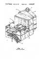
- FIG. 1shows an isometric view of one form of the apparatus
- FIG. 2shows a top view of the apparatus of FIG. 1;
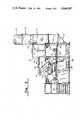
- FIG. 3shows a side elevation view in partial cross section
- FIG. 4shows an end elevation view of the apparatus of FIG. 1;
- FIG. 5shows a symbolic diagram of certain of the electrical and mechanical components of the invention.
- FIG. 6shows a schematic diagram of the turntable drive mechanism
- FIG. 7shows a diagram of the resolver coupling.
- a work center 10is adapted for positioning on the floor of an industrial plant or other facility, and it is presumed electrical power and water is supplied work center 10 from external sources.
- Work center 10includes an elevated platform 12 which is surrounded by a suitable fence 13, and is positioned adjacent to an enclosure 14 having an opening facing platform 12.
- Enclosure 14has a hood 16 and exhaust duct 18 mounted to an opening in hood 16.
- a stairway 20provides access to platform 12, and an opening 22 through fence 13 provides an access position to entry on platform 12.
- a rotatable turntable 25is fixed above platform 12 and is rotatably positionable about spindle 24 (FIG. 3).
- a robot manipulator 30is fixedly positioned relative to spindle 24, and clearance is provided beneath robot manipulator 30 to enable the free rotation of turntable 25 intermediate robot manipulator 30 and platform 12.
- Access space 26is provided beneath platform 12 for the housing of electrical and mechanical equipment as hereinafter described.
- a portion 12a of platform 12may be formed of an open grillwork or mesh, immediately adjacent to the opening in enclosure 14.
- Work center 10may be made of any convenient dimensions, and in the preferred embodiment it has been determined that a platform of square dimensions of twelve feet on each side is adequate for the intended purpose. Enclosure 14 may extend a distance of approximately eight feet above platform 12, and platform 12 may be positioned approximately four feet above the floor level.
- FIG. 2shows a top view of one form of the invention, and illustrates the cooperative relationship between the respective moving components on platform 12.
- Turntable 25is rotatably positionable to turn about a circular arc 28, and contains two or more parts mounting stations.
- Turntable 25may be formed into any number of parts mounting configurations, although a preferred construction showing two parts mounting stations 27a and 27b is shown in FIG. 2. It is apparent that an alternative construction having four parts mounting stations could readily be formed by adding two additional legs extending from spindle 24 at right angles to the construction shown on FIG. 2. Parts mounting stations 27a and 27b travel along a circular arc 28 as turntable 25 is rotated about spindle 24.
- Station 27ais shown in a loading and unloading position
- station 27bis shown in a finishing position wherein a spray finishing operation may be performed.
- the robot manipulator 30is fixedly attached to a cantilevered arm 31 (FIG. 3) extending from the center of spindle 24.
- a rotatable body 34is mounted on cantilever arm 31, and is pivotal about a vertical axis 35 extending normal to arm 31.
- Arms 33 and 36are connected to rotatable body 34, and a flexible wrist mechanism 38 is connected to the forward end of arm 36.
- Spray applicator 32is attached at the forward end of flexible wrist 38, and is manipulable by the computer controls which actuate robot manipulator 30 to perform a spray finishing operation.
- a type of robot manipulator 30 which is well-suited for use in the present inventionis disclosed in U.S. Pat. No. 4,531,885, issued July 30, 1985, which disclosure is incorporated by a reference herein.
- the servomechanisms which control the movement of the various members of this robot manipulatorare adapted for connection to a digital computer processor, and the movements of the members can be programmed into the processor for subsequent control of movement by the processor.
- servomechanismscan be connected to turntable 25 and to the processor which controls robot manipulator 30 so that rotational movement and position of turntable 25 can be programmed into the processor and can be subsequently initiated under processor control.
- the servomechanisms and digital computer communications techniques necessary for the processor control of turntable 25are readily determinable by those having skill in this art.
- the spray head of spray applicator 32is positionable under computer control to any point within an envelope defined by arcuate lines 40 and 42 and radial lines 44 and 46, which radial lines emanate from vertical axis 35. Spray finishing operations are possible at any position inside of the envelope so defined, and it can be seen that the circular arc 28 which defines the rotatable position of parts mounting stations 27a and 27b is within this envelope over approximately ninety degrees of its arcuate distance.
- turntable 25 and spray applicator 32can be cooperatively positioned relative to each other to accomplish spray painting of parts or other objects placed on turntable 25 to permit a wide range of spraying positions.
- FIG. 3shows a side elevation view of work center 10 in partial cross section.
- Turntable 25is rotatably mounted to platform 12 by means of plate bearing assembly 48.
- Plate bearing assembly 48is constructed so as to provide free rotational movement between an upper and lower bearing member, the upper bearing member being attached to turntable 25 and the lower bearing member being attached to platform 12.
- An opening through the center of plate bearing assembly 48permits the passage of spindle 24, which projects upwardly above turntable 25 and is fixedly attached to platform 12 and to the base of work center 10 by means of a mounting plate 50.
- Spindle 24has rigidly affixed thereto a cantilever arm 31 which projects toward the rear of work center 10.
- Rotatable body 34is pivotally attached to arm 31 at vertical axis 35. This attachment is made by means of a mounting plate 37 rigidly attached to arm 31 and rotatably attached to body 34.
- Robot manipulator 30has a generally upwardly extending arm 33 which is pivotable about a horizontal axis 39 at its lower end, contained in rotatable body 34. A second horizontal axis 41 at the upper end of arm 33 is coupled to arm 36 and permits pivotal motion of arm 36 about axis 41.
- Flexible wrist 38is movable in three directions on the end of arm 36, the three directions being defined as roll, pitch and yaw.
- Spray applicator 32is fixedly attached at the end of flexible wrist 38, and is therefore movable over a wide range of positions. Altogether, robot manipulator 30 has freedom of movement over six axes of motion.
- a spray booth and air exhaust systemis constructed about enclosure 14.
- Enclosure 14is preferably constructed of sheet metal, and has an opening 15 facing robot manipulator 30.
- Enclosure 14extends downwardly below platform 12 to form an air duct 17 which opens into a grating 12a which forms a portion of platform 12.
- Exhaust duct 18is connected to a blower or source of suction (not shown) to cause air to be drawn upwardly through grating 12a, and to be directed by air duct 17 into the rear portion of enclosure 14, and thereafter upwardly through hood 16 and exhaust duct 18.
- This air flowis used to convey paint overspray and residue away from the area of the spray painting station 27b.
- a water flood sheet 52may be provided for collecting additional overspray immediately behind spray station 27b.
- Water flood sheet 52is supplied with a continuous curtain of water from a water reservoir 54, which flows downwardly through an opening 55 in platform 12 into a water collection tank 56.
- the collected water in tank 56is filtered and recirculated back to reservoir 54 according to principles which are well known in the art.
- Water flood sheet 52preferably extends over the entire width of enclosure 14, and water tank 56 is preferably constructed to receive drainage over this entire width.
- Air duct 17is constructed so as to provide openings for the return flow of water from water flood sheet 52 into tank 56, and exhaust air is directed to flow through the curtain of water which falls downwardly through opening 55.
- FIG. 4shows an end elevation view of work station 10.
- Enclosure 14extends across the entire width of work station 10, and water flood sheet 52 similarly extends over the entire width of enclosure 14.
- Robot manipulator 30is centrally positioned on platform 12 to provide equal areas of spray application on either side of spindle axis 24.
- Platform 12is preferably positioned at a height of approximately four feet above base frame 58, thereby to provide a sizable volume of access space 26, for the mounting of operational equipment associated with work center 10.
- spray applicator 32frequently requires a source of compressed air, and the air compressor and the pneumatic equipment required for providing this air may conveniently be positioned beneath platform 12 in access space 26.
- the apparatusrequires a source of electrical power and a source of pressurized hydraulic fluid for driving the various servomechanisms associated with the apparatus.
- This equipmentmay also be positioned beneath platform 12, and all necessary lines and cables required for delivery of power to the robot manipulator 30 and turntable 25 may be fed through spindle 24.
- the hoses and electrical connections required by robot manipulator 30are passed through a central hollow opening through spindle 24.
- FIG. 5shows a symbolic diagram of certain electrical and mechanical components of the invention. These components are placed in physical proximity to the respective members of robot manipulator 30 and turntable 25, and certain of the components are placed in access space 26 beneath platform 12. Where required, certain electrical, hydraulic, air and coating material lines may be fed from beneath platform 12 through the opening in spindle 24 to connect to the appropriate control or drive mechanism.
- Digital processor 60may conveniently be placed in access space 26, together with memory 61. Processor 60 and memory 61 interact in a conventional manner which is well known in the art of computer processing.
- Control panel 62may be positioned at any convenient location, either above platform 12 or in access space 26. Control panel 62 may contain certain switching controls to be activated by an operator, and may also contain various light indicators to provide an indication of the operation of the system.
- a number of servomechanism devicesare located inside of robot manipulator 30, and the servomechanism devices typically include hydraulically actuable driving members for imparting rotational or linear movement about the respective axes defined with respect to robot manipulator 30. These servomechanisms also include shaft encoders or other equivalent devices for translating rotational and/or linear movement into digitally representative quantities for transmission to the processor 60.
- servomechanisms 64, 66, 68are preferably hydraulically actuable pistons and cylinders, for imparting linear motion to a servo crank arm connected about each of the axes 35, 39, 41.
- servomechanisms 64, 66, 68are encoders for responding to linear displacements, and for generating electrical signals representative of such linear displacements.
- Servomechanisms 70, 72, 74are associated with the respective motions that may be imparted to flexible wrist 38, and which have been defined “roll", “pitch” and “yaw”. Each of these servomechanisms also includes a digital translator for generating electrical signals representative of the respective motions.
- a spray control 75may be a solenoid-actuated valve or other similar device, and is utilized to actuate the spray applicator 32. In particular instances, spray device 75 may also include mechanisms for controlling air supplied to spray applicator 32.
- a servomechanism 76forms a part of turntable 25, and serves to impart the rotational motion of turntable 25 about axis 24.
- Servomechanism 76may be an electrical or hydraulically actuated motor or motors which is gear-coupled between turntable 25 and platform 12 for imparting the necessary rotational movement.
- a digital encoding deviceis included as a part of servomechanism 76 for generating electrical signals representative of the rotational position of turntable 25.
- Digital processor 60is connected in data transfer communication with all of the respective servomechanisms, according to well-known techniques, so as to generate driving signals to actuate the respective servomechanisms and control the movements associated with them.
- the digital encoding devicesare similarly connected to the respective servomechanisms and processor 60, and processor 60 is programmed so as to periodically sample the signals generated by these encoding devices to provide a digital indication of position.
- Processor 60is controlled by a program which is prestored in memory 61, and is adapted for execution by processor 60 so as to maintain coordinated control over the actuation of all servomechanisms, and to periodically receive positional information from the servomechanisms to monitor actual positions of the respective members.
- FIG. 6shows a schematic diagram of the servomechanism 76, which drives turntable 25 in response to signals from processor 60, and which transmits positional information to processor 60.
- a ring gear 80is affixed to the upper bearing member of plate bearing assembly 48, and is therefore affixed to turntable 25.
- a pair of hydraulic motors 82 and 84are affixed to platform 12, each of the motors 82 and 84 having a pinion gear engaged with ring gear 80. Motors 82 and 84 are driven in the rotational direction shown by the respective arrows, from a supply of pressurized hydraulic oil which is coupled to the motors via a servo valve 85.
- Servo valve 85is a two-position valve, conveying the pressurized supply of oil to either motor 82 or to motor 84, and at the same time conveying a return supply of oil from the hydraulic motor not engaged by the pressurized oil.
- the return oilis directed back to an oil reservoir from which the pressurized oil supply is drawn.
- the pressure oil supplyis delivered via servo valve 85 to hydraulic motor 84, and hydraulic motor 82 is coupled to a return line.
- the pressurized supply of oilis delivered to motor 82 via servo valve 85 and the return line is coupled to motor 84.
- FIG. 7shows an enlarged view of the gearing relationship between resolver 88 and ring gear 80.
- Pinion gear 89is comprised of a first gear portion 89a, which is affixed to resolver shaft 87 and rotates therewith.
- Pinion gear 89also includes a pinion gear section 89b, which is coupled to shaft 87 via a bearing, and is freely rotatable independent of shaft 87.
- Pinion gear sections 89a and 89bare connected together via a coil spring 90, and pinion gear sections 89a and 89b each have respective teeth for engagement against ring gear 80.
- the coil spring 90Prior to engaging pinion gear sections 89a and 89b against the teeth of ring gear 80, the coil spring 90 is tightened by rotating gear section 89b relative to gear section 89a. After a predetermined spring force has been developed the respective gear sections are placed into engagement with ring gear 80, and coil spring 90 forces the respective pinion gear sections into oppositely directed engagement against respective teeth surfaces of ring gear 80. This eliminates any backlash or tolerance error in connection with shaft 87 of resolver 88, and thereby eliminates any positional inaccuracies which might otherwise result from resolver 88.
- processor 60is programmed so as to provide the desired positioning of spray applicator 32 with respect to parts mounted on turntable 25 for applying coating material thereto.
- Processor 60incrementally rotates turntable 25 so as to place a parts mounting station in front of enclosure 14, and thereafter to manipulate spray applicator 32 and the controls which actuate spray applicator 32 to permit the selective release of coating materials upon the parts surfaces.
- spray applicator 32has been appropriately maneuvered to insure that coating materials are evenly distributed over all of the desired surfaces of the parts located on turntable 25, turntable 25 may then be incrementally rotated to position a new parts mounting station in front of enclosure 14.
- a different parts mounting station on turntable 25is positioned proximate access opening 22, and previously coated parts may be removed from the turntable and a new supply of parts may be attached to the turntable for subsequent coating.
- This processmay be continued for so long as desired, and if parts having different surface configurations are attached to turntable 25 it is only necessary to implement a different software routine in digital processor 60 in order to provide the necessary positional control over spray applicator 32 and the turntable 25.
- the operatormay communicate a particular parts configuration to digital processor 60 by means of control keys on control panel 62. It is therefore apparent that a wide variety and mix of parts configurations may be automatically positioned and coated by the apparatus described herein, where only inloading and unloading of the parts is necessarily accomplished under manual control.
Landscapes
- Engineering & Computer Science (AREA)
- Robotics (AREA)
- Mechanical Engineering (AREA)
- Spray Control Apparatus (AREA)
- Manipulator (AREA)
Abstract
Description
Claims (16)
Priority Applications (1)
| Application Number | Priority Date | Filing Date | Title |
|---|---|---|---|
| US06/782,430US4644897A (en) | 1985-10-01 | 1985-10-01 | Modular robotic finishing work center |
Applications Claiming Priority (1)
| Application Number | Priority Date | Filing Date | Title |
|---|---|---|---|
| US06/782,430US4644897A (en) | 1985-10-01 | 1985-10-01 | Modular robotic finishing work center |
Publications (1)
| Publication Number | Publication Date |
|---|---|
| US4644897Atrue US4644897A (en) | 1987-02-24 |
Family
ID=25126028
Family Applications (1)
| Application Number | Title | Priority Date | Filing Date |
|---|---|---|---|
| US06/782,430Expired - LifetimeUS4644897A (en) | 1985-10-01 | 1985-10-01 | Modular robotic finishing work center |
Country Status (1)
| Country | Link |
|---|---|
| US (1) | US4644897A (en) |
Cited By (22)
| Publication number | Priority date | Publication date | Assignee | Title |
|---|---|---|---|---|
| US4764077A (en)* | 1986-04-18 | 1988-08-16 | Thermwood Corporation | Assembly for performing work functions on a workpiece |
| US4845639A (en)* | 1987-12-11 | 1989-07-04 | Robotic Vision Systems, Inc. | Robotic sealant calibration |
| US4990201A (en)* | 1989-04-14 | 1991-02-05 | The Boeing Company | Method for reticulating perforated sheets |
| US5456561A (en)* | 1989-03-07 | 1995-10-10 | Ade Corporation | Robot prealigner |
| EP0723817A1 (en)* | 1995-01-26 | 1996-07-31 | Hilt Equipements Industriels | Booth for treating workpieces by spraying |
| US5760560A (en)* | 1993-10-21 | 1998-06-02 | Fanuc, Ltd. | Robot apparatus |
| US6435397B2 (en) | 2000-04-18 | 2002-08-20 | Progressive Tool & Industries Co. | Robotic turntable |
| US6641666B2 (en)* | 1999-11-15 | 2003-11-04 | Ppg Industries Ohio, Inc. | Method and apparatus for coating a substrate |
| US6662083B2 (en) | 2000-10-31 | 2003-12-09 | Progressive Tool & Industries Co. | Multiple robotic workstation with multiple fixtures |
| EP1413360A3 (en)* | 2002-07-23 | 2006-05-10 | Eastman Kodak Company | Apparatus and method of material deposition using compressed fluids |
| US20070243075A1 (en)* | 2006-04-17 | 2007-10-18 | Kawasaki Jukogyo Kabushiki Kaisha | Carrying system and processing equipment |
| WO2009043369A1 (en)* | 2007-10-01 | 2009-04-09 | Abb Technology Ab | A method for controlling a plurality of axes in an industrial robot system and an industrial robot system |
| CN103204379A (en)* | 2012-01-11 | 2013-07-17 | 株式会社安川电机 | Carrier Device And Robot System |
| US20130331989A1 (en)* | 2012-06-08 | 2013-12-12 | Kabushiki Kaisha Yaskawa Denki | Robot cell, assembling method of robot cell, and robot system |
| WO2016202922A1 (en)* | 2015-06-17 | 2016-12-22 | Yaskawa Nordic Ab | A robot cell comprising an industrial robot and a positioner |
| CN106476016A (en)* | 2015-08-28 | 2017-03-08 | 株式会社大福 | Process equipment and processing method |
| US20190022851A1 (en)* | 2017-07-20 | 2019-01-24 | Kabushiki Kaisha Yaskawa Denki | Robot system and method for controlling robot system |
| US10578098B2 (en) | 2005-07-13 | 2020-03-03 | Baxter International Inc. | Medical fluid delivery device actuated via motive fluid |
| JP2021522996A (en)* | 2018-05-03 | 2021-09-02 | ファナック アメリカ コーポレイション | Painting booth using robot and operation method |
| EP3351496B1 (en)* | 2015-09-16 | 2022-04-20 | BOE Technology Group Co., Ltd. | Double-sided adhesive tape attaching apparatus and method for attaching double-sided adhesive tape |
| US11478578B2 (en) | 2012-06-08 | 2022-10-25 | Fresenius Medical Care Holdings, Inc. | Medical fluid cassettes and related systems and methods |
| CN116273607A (en)* | 2023-02-23 | 2023-06-23 | 福建世高智能科技有限公司 | Spraying equipment |
Citations (8)
| Publication number | Priority date | Publication date | Assignee | Title |
|---|---|---|---|---|
| US3932151A (en)* | 1973-02-12 | 1976-01-13 | Binks Manufacturing Company | Spray booth |
| SU691211A1 (en)* | 1978-04-03 | 1979-10-15 | Производственное Объединение "Ростсельмаш" | Painting spraying chamber |
| US4187454A (en)* | 1977-04-30 | 1980-02-05 | Tokico Ltd. | Industrial robot |
| DE2942184A1 (en)* | 1979-10-18 | 1981-04-30 | Bruno 7441 Wolfschlugen Kümmerle | Recycling installation for ventilation systems - used for painting and similar operations and includes cooling machine with connections for both condenser and evaporator |
| US4348731A (en)* | 1979-03-05 | 1982-09-07 | Hitachi, Ltd. | Automatic working apparatus and method of controlling the same |
| US4378959A (en)* | 1979-06-13 | 1983-04-05 | Thermwood Corporation | Apparatus for performing work functions |
| US4531885A (en)* | 1981-10-05 | 1985-07-30 | Graco Robotics, Inc. | Device for robot manipulator |
| US4532148A (en)* | 1983-04-01 | 1985-07-30 | General Motors Corporation | Robot painting system for automobiles |
- 1985
- 1985-10-01USUS06/782,430patent/US4644897A/ennot_activeExpired - Lifetime
Patent Citations (8)
| Publication number | Priority date | Publication date | Assignee | Title |
|---|---|---|---|---|
| US3932151A (en)* | 1973-02-12 | 1976-01-13 | Binks Manufacturing Company | Spray booth |
| US4187454A (en)* | 1977-04-30 | 1980-02-05 | Tokico Ltd. | Industrial robot |
| SU691211A1 (en)* | 1978-04-03 | 1979-10-15 | Производственное Объединение "Ростсельмаш" | Painting spraying chamber |
| US4348731A (en)* | 1979-03-05 | 1982-09-07 | Hitachi, Ltd. | Automatic working apparatus and method of controlling the same |
| US4378959A (en)* | 1979-06-13 | 1983-04-05 | Thermwood Corporation | Apparatus for performing work functions |
| DE2942184A1 (en)* | 1979-10-18 | 1981-04-30 | Bruno 7441 Wolfschlugen Kümmerle | Recycling installation for ventilation systems - used for painting and similar operations and includes cooling machine with connections for both condenser and evaporator |
| US4531885A (en)* | 1981-10-05 | 1985-07-30 | Graco Robotics, Inc. | Device for robot manipulator |
| US4532148A (en)* | 1983-04-01 | 1985-07-30 | General Motors Corporation | Robot painting system for automobiles |
Cited By (39)
| Publication number | Priority date | Publication date | Assignee | Title |
|---|---|---|---|---|
| US4764077A (en)* | 1986-04-18 | 1988-08-16 | Thermwood Corporation | Assembly for performing work functions on a workpiece |
| US4845639A (en)* | 1987-12-11 | 1989-07-04 | Robotic Vision Systems, Inc. | Robotic sealant calibration |
| US5456561A (en)* | 1989-03-07 | 1995-10-10 | Ade Corporation | Robot prealigner |
| US4990201A (en)* | 1989-04-14 | 1991-02-05 | The Boeing Company | Method for reticulating perforated sheets |
| US5760560A (en)* | 1993-10-21 | 1998-06-02 | Fanuc, Ltd. | Robot apparatus |
| EP0723817A1 (en)* | 1995-01-26 | 1996-07-31 | Hilt Equipements Industriels | Booth for treating workpieces by spraying |
| FR2729871A1 (en)* | 1995-01-26 | 1996-08-02 | Hilt Equip Ind | SPRAY PARTS TREATMENT CABIN |
| US6641666B2 (en)* | 1999-11-15 | 2003-11-04 | Ppg Industries Ohio, Inc. | Method and apparatus for coating a substrate |
| US6435397B2 (en) | 2000-04-18 | 2002-08-20 | Progressive Tool & Industries Co. | Robotic turntable |
| US6651867B2 (en) | 2000-04-18 | 2003-11-25 | Progressive Tool & Industries Co. | Robotic turntable |
| US6662083B2 (en) | 2000-10-31 | 2003-12-09 | Progressive Tool & Industries Co. | Multiple robotic workstation with multiple fixtures |
| EP1413360A3 (en)* | 2002-07-23 | 2006-05-10 | Eastman Kodak Company | Apparatus and method of material deposition using compressed fluids |
| US10578098B2 (en) | 2005-07-13 | 2020-03-03 | Baxter International Inc. | Medical fluid delivery device actuated via motive fluid |
| US12392335B2 (en) | 2005-07-13 | 2025-08-19 | Baxter International Inc. | Medical fluid pumping system having backflow prevention |
| US11384748B2 (en) | 2005-07-13 | 2022-07-12 | Baxter International Inc. | Blood treatment system having pulsatile blood intake |
| US10670005B2 (en) | 2005-07-13 | 2020-06-02 | Baxter International Inc. | Diaphragm pumps and pumping systems |
| US10590924B2 (en) | 2005-07-13 | 2020-03-17 | Baxter International Inc. | Medical fluid pumping system including pump and machine chassis mounting regime |
| US20070243075A1 (en)* | 2006-04-17 | 2007-10-18 | Kawasaki Jukogyo Kabushiki Kaisha | Carrying system and processing equipment |
| EP1870166A3 (en)* | 2006-04-17 | 2008-12-10 | Kawasaki Jukogyo Kabushiki Kaisha | Carrying system and processing equipment |
| US7900578B2 (en) | 2006-04-17 | 2011-03-08 | Kawasaki Jukogyo Kabushiki Kaisha | Carrying system and processing equipment |
| WO2009043369A1 (en)* | 2007-10-01 | 2009-04-09 | Abb Technology Ab | A method for controlling a plurality of axes in an industrial robot system and an industrial robot system |
| CN101984750B (en)* | 2007-10-01 | 2013-01-09 | Abb技术有限公司 | A method for controlling a plurality of axes in an industrial robot system and an industrial robot system |
| US8452443B2 (en) | 2007-10-01 | 2013-05-28 | Abb Research Ltd | Method for controlling a plurality of axes in an industrial robot system and an industrial robot system |
| CN103204379A (en)* | 2012-01-11 | 2013-07-17 | 株式会社安川电机 | Carrier Device And Robot System |
| CN103204379B (en)* | 2012-01-11 | 2015-09-02 | 株式会社安川电机 | Handling device and robot system |
| EP2614932A1 (en)* | 2012-01-11 | 2013-07-17 | Kabushiki Kaisha Yaskawa Denki | Carrier device and robot system |
| US9126330B2 (en) | 2012-01-11 | 2015-09-08 | Kabushiki Kaisha Yaskawa Denki | Carrier device and robot system |
| US11478578B2 (en) | 2012-06-08 | 2022-10-25 | Fresenius Medical Care Holdings, Inc. | Medical fluid cassettes and related systems and methods |
| US20130331989A1 (en)* | 2012-06-08 | 2013-12-12 | Kabushiki Kaisha Yaskawa Denki | Robot cell, assembling method of robot cell, and robot system |
| WO2016202922A1 (en)* | 2015-06-17 | 2016-12-22 | Yaskawa Nordic Ab | A robot cell comprising an industrial robot and a positioner |
| CN106476016B (en)* | 2015-08-28 | 2020-01-21 | 株式会社大福 | Processing equipment and processing method |
| CN106476016A (en)* | 2015-08-28 | 2017-03-08 | 株式会社大福 | Process equipment and processing method |
| EP3351496B1 (en)* | 2015-09-16 | 2022-04-20 | BOE Technology Group Co., Ltd. | Double-sided adhesive tape attaching apparatus and method for attaching double-sided adhesive tape |
| US10888992B2 (en)* | 2017-07-20 | 2021-01-12 | Kabushiki Kaisha Yaskawa Denki | Robot system and method for controlling robot system |
| JP2019018320A (en)* | 2017-07-20 | 2019-02-07 | 株式会社安川電機 | Robot system |
| US20190022851A1 (en)* | 2017-07-20 | 2019-01-24 | Kabushiki Kaisha Yaskawa Denki | Robot system and method for controlling robot system |
| JP2021522996A (en)* | 2018-05-03 | 2021-09-02 | ファナック アメリカ コーポレイション | Painting booth using robot and operation method |
| US11383258B2 (en)* | 2018-05-03 | 2022-07-12 | Fanuc America Corporation | Robotic painting booth and operating method |
| CN116273607A (en)* | 2023-02-23 | 2023-06-23 | 福建世高智能科技有限公司 | Spraying equipment |
Similar Documents
| Publication | Publication Date | Title |
|---|---|---|
| US4644897A (en) | Modular robotic finishing work center | |
| US5248341A (en) | Robotic carrier mechanism for aircraft maintenance | |
| US4239431A (en) | Light-weight program controller | |
| CA1247167A (en) | End-of-arm tooling carousel apparatus for use with a robot | |
| EP0484173B1 (en) | Robotic arm for maintaining a tool in a desired orientation | |
| Briones et al. | Wall-climbing robot for inspection in nuclear power plants | |
| US8726832B2 (en) | Painting system having a wall-mounted robot | |
| US4832563A (en) | Portal system | |
| KR100503113B1 (en) | Ordinary our-face painting machine | |
| US4764077A (en) | Assembly for performing work functions on a workpiece | |
| GB1561260A (en) | Programmable manipulators | |
| US20070169691A1 (en) | Automatic retouching device for a powder-coating booth | |
| US4547120A (en) | Manipulator robot | |
| RU2104807C1 (en) | Robot installation for painting of objects | |
| KR20020075898A (en) | Sprayer device in particular for a motor vehicle body paint spray booth | |
| US4684312A (en) | Robotic wrist | |
| Kangari et al. | Automation in construction | |
| WO1991014539A1 (en) | Robotic system for paint removal | |
| CA1307306C (en) | Industrial robot device | |
| USRE32794E (en) | Programmable automatic assembly system | |
| US4455965A (en) | Automatic process and system for painting motor vehicle interiors | |
| US4370836A (en) | Universal abrasive cleaning apparatus | |
| JP2645312B2 (en) | Method and apparatus for spraying cycloids using twin guns | |
| JPS61216762A (en) | Applicator | |
| JPH05192615A (en) | Automatic painting equipment |
Legal Events
| Date | Code | Title | Description |
|---|---|---|---|
| AS | Assignment | Owner name:GRACO ROBOTICS, INC., 12898 WESTMORE AVENUE, LIVON Free format text:ASSIGNMENT OF ASSIGNORS INTEREST.;ASSIGNOR:FENDER, NORMAN N.;REEL/FRAME:004627/0902 Effective date:19850927 | |
| STCF | Information on status: patent grant | Free format text:PATENTED CASE | |
| FEPP | Fee payment procedure | Free format text:PAYOR NUMBER ASSIGNED (ORIGINAL EVENT CODE: ASPN); ENTITY STATUS OF PATENT OWNER: LARGE ENTITY | |
| FPAY | Fee payment | Year of fee payment:4 | |
| FEPP | Fee payment procedure | Free format text:PAYER NUMBER DE-ASSIGNED (ORIGINAL EVENT CODE: RMPN); ENTITY STATUS OF PATENT OWNER: LARGE ENTITY Free format text:PAYOR NUMBER ASSIGNED (ORIGINAL EVENT CODE: ASPN); ENTITY STATUS OF PATENT OWNER: LARGE ENTITY | |
| AS | Assignment | Owner name:ABB TRALLFA ROBOT A/S A CORP. OF NORWAY, NORWAY Free format text:ASSIGNMENT OF ASSIGNORS INTEREST.;ASSIGNOR:ABB ROBOTICS FINISHING INC., A OH CORP.;REEL/FRAME:006258/0305 Effective date:19910629 | |
| AS | Assignment | Owner name:ABB ROBOTICS FINISHING INC. A CORPORATION OF OHI Free format text:ASSIGNMENT OF ASSIGNORS INTEREST.;ASSIGNOR:GRACO ROBOTICS INC., A DE CORP.;REEL/FRAME:006258/0301 Effective date:19910628 | |
| FPAY | Fee payment | Year of fee payment:8 | |
| FPAY | Fee payment | Year of fee payment:12 |