US4643889A - System for generation of singlet-delta oxygen - Google Patents
System for generation of singlet-delta oxygenDownload PDFInfo
- Publication number
- US4643889A US4643889AUS06/846,254US84625486AUS4643889AUS 4643889 AUS4643889 AUS 4643889AUS 84625486 AUS84625486 AUS 84625486AUS 4643889 AUS4643889 AUS 4643889A
- Authority
- US
- United States
- Prior art keywords
- aqueous solution
- process according
- gas
- layer
- mixed aqueous
- Prior art date
- Legal status (The legal status is an assumption and is not a legal conclusion. Google has not performed a legal analysis and makes no representation as to the accuracy of the status listed.)
- Expired - Fee Related
Links
- QVGXLLKOCUKJST-UHFFFAOYSA-Natomic oxygenChemical compound[O]QVGXLLKOCUKJST-UHFFFAOYSA-N0.000titledescription5
- 239000001301oxygenSubstances0.000titledescription5
- 229910052760oxygenInorganic materials0.000titledescription5
- 239000007864aqueous solutionSubstances0.000claimsabstractdescription70
- 239000007789gasSubstances0.000claimsabstractdescription59
- 239000000463materialSubstances0.000claimsabstractdescription35
- KZBUYRJDOAKODT-UHFFFAOYSA-NChlorineChemical compoundClClKZBUYRJDOAKODT-UHFFFAOYSA-N0.000claimsabstractdescription30
- MYMOFIZGZYHOMD-UHFFFAOYSA-NDioxygenChemical compoundO=OMYMOFIZGZYHOMD-UHFFFAOYSA-N0.000claimsabstractdescription28
- 229910001882dioxygenInorganic materials0.000claimsabstractdescription28
- 238000000034methodMethods0.000claimsabstractdescription26
- MHAJPDPJQMAIIY-UHFFFAOYSA-NHydrogen peroxideChemical compoundOOMHAJPDPJQMAIIY-UHFFFAOYSA-N0.000claimsabstractdescription22
- 239000000203mixtureSubstances0.000claimsabstractdescription10
- 230000001939inductive effectEffects0.000claimsabstractdescription3
- 230000035515penetrationEffects0.000claimsabstractdescription3
- 238000006243chemical reactionMethods0.000claimsdescription36
- 239000007788liquidSubstances0.000claimsdescription12
- 239000011148porous materialSubstances0.000claimsdescription9
- 239000000919ceramicSubstances0.000claimsdescription7
- XLYOFNOQVPJJNP-UHFFFAOYSA-MhydroxideChemical compound[OH-]XLYOFNOQVPJJNP-UHFFFAOYSA-M0.000claimsdescription3
- 229910052783alkali metalInorganic materials0.000claimsdescription2
- 150000008044alkali metal hydroxidesChemical class0.000claimsdescription2
- 150000001340alkali metalsChemical class0.000claimsdescription2
- 229910052784alkaline earth metalInorganic materials0.000claimsdescription2
- 150000001342alkaline earth metalsChemical class0.000claimsdescription2
- 229910052751metalInorganic materials0.000claimsdescription2
- 239000002184metalSubstances0.000claimsdescription2
- 239000011368organic materialSubstances0.000claimsdescription2
- 239000005373porous glassSubstances0.000claimsdescription2
- HEMHJVSKTPXQMS-UHFFFAOYSA-MSodium hydroxideChemical compound[OH-].[Na+]HEMHJVSKTPXQMS-UHFFFAOYSA-M0.000description18
- 239000000460chlorineSubstances0.000description10
- 229910052801chlorineInorganic materials0.000description8
- ZAMOUSCENKQFHK-UHFFFAOYSA-NChlorine atomChemical compound[Cl]ZAMOUSCENKQFHK-UHFFFAOYSA-N0.000description7
- IJGRMHOSHXDMSA-UHFFFAOYSA-NAtomic nitrogenChemical compoundN#NIJGRMHOSHXDMSA-UHFFFAOYSA-N0.000description6
- KWYUFKZDYYNOTN-UHFFFAOYSA-MPotassium hydroxideChemical compound[OH-].[K+]KWYUFKZDYYNOTN-UHFFFAOYSA-M0.000description6
- 239000000243solutionSubstances0.000description6
- 239000011521glassSubstances0.000description4
- 239000012528membraneSubstances0.000description4
- WMFOQBRAJBCJND-UHFFFAOYSA-MLithium hydroxideChemical compound[Li+].[OH-]WMFOQBRAJBCJND-UHFFFAOYSA-M0.000description3
- 229910052757nitrogenInorganic materials0.000description3
- ZCYVEMRRCGMTRW-UHFFFAOYSA-N7553-56-2Chemical compound[I]ZCYVEMRRCGMTRW-UHFFFAOYSA-N0.000description2
- XKRFYHLGVUSROY-UHFFFAOYSA-NArgonChemical compound[Ar]XKRFYHLGVUSROY-UHFFFAOYSA-N0.000description2
- CURLTUGMZLYLDI-UHFFFAOYSA-NCarbon dioxideChemical compoundO=C=OCURLTUGMZLYLDI-UHFFFAOYSA-N0.000description2
- LFQSCWFLJHTTHZ-UHFFFAOYSA-NEthanolChemical compoundCCOLFQSCWFLJHTTHZ-UHFFFAOYSA-N0.000description2
- 239000003513alkaliSubstances0.000description2
- 235000011089carbon dioxideNutrition0.000description2
- 229910052740iodineInorganic materials0.000description2
- PNDPGZBMCMUPRI-UHFFFAOYSA-NiodineChemical compoundIIPNDPGZBMCMUPRI-UHFFFAOYSA-N0.000description2
- 239000011630iodineSubstances0.000description2
- -1polypropylenePolymers0.000description2
- VEXZGXHMUGYJMC-UHFFFAOYSA-MChloride anionChemical compound[Cl-]VEXZGXHMUGYJMC-UHFFFAOYSA-M0.000description1
- YCKRFDGAMUMZLT-UHFFFAOYSA-NFluorine atomChemical compound[F]YCKRFDGAMUMZLT-UHFFFAOYSA-N0.000description1
- 239000004743PolypropyleneSubstances0.000description1
- 229910052786argonInorganic materials0.000description1
- 230000015572biosynthetic processEffects0.000description1
- AXCZMVOFGPJBDE-UHFFFAOYSA-Lcalcium dihydroxideChemical compound[OH-].[OH-].[Ca+2]AXCZMVOFGPJBDE-UHFFFAOYSA-L0.000description1
- 239000000920calcium hydroxideSubstances0.000description1
- 229910001861calcium hydroxideInorganic materials0.000description1
- 230000001186cumulative effectEffects0.000description1
- 238000010586diagramMethods0.000description1
- 238000007599dischargingMethods0.000description1
- 238000002474experimental methodMethods0.000description1
- 229910052731fluorineInorganic materials0.000description1
- 239000011737fluorineSubstances0.000description1
- 230000005283ground stateEffects0.000description1
- 239000001307heliumSubstances0.000description1
- 229910052734heliumInorganic materials0.000description1
- SWQJXJOGLNCZEY-UHFFFAOYSA-Nhelium atomChemical compound[He]SWQJXJOGLNCZEY-UHFFFAOYSA-N0.000description1
- 239000012510hollow fiberSubstances0.000description1
- 239000011261inert gasSubstances0.000description1
- VTHJTEIRLNZDEV-UHFFFAOYSA-Lmagnesium dihydroxideChemical compound[OH-].[OH-].[Mg+2]VTHJTEIRLNZDEV-UHFFFAOYSA-L0.000description1
- 239000000347magnesium hydroxideSubstances0.000description1
- 229910001862magnesium hydroxideInorganic materials0.000description1
- 238000005259measurementMethods0.000description1
- 239000011259mixed solutionSubstances0.000description1
- 230000000149penetrating effectEffects0.000description1
- 230000035699permeabilityEffects0.000description1
- 229920001155polypropylenePolymers0.000description1
- 229920000915polyvinyl chloridePolymers0.000description1
- 239000004800polyvinyl chlorideSubstances0.000description1
- 239000000376reactantSubstances0.000description1
- 239000011347resinSubstances0.000description1
- 229920005989resinPolymers0.000description1
- 239000000126substanceSubstances0.000description1
- 230000007704transitionEffects0.000description1
- XLYOFNOQVPJJNP-UHFFFAOYSA-NwaterSubstancesOXLYOFNOQVPJJNP-UHFFFAOYSA-N0.000description1
- 238000009736wettingMethods0.000description1
Images


Classifications
- C—CHEMISTRY; METALLURGY
- C01—INORGANIC CHEMISTRY
- C01B—NON-METALLIC ELEMENTS; COMPOUNDS THEREOF; METALLOIDS OR COMPOUNDS THEREOF NOT COVERED BY SUBCLASS C01C
- C01B13/00—Oxygen; Ozone; Oxides or hydroxides in general
- C01B13/02—Preparation of oxygen
Definitions
- This inventionrelates to a system for the generation of singlet-delta oxygen, and more particularly it relates to an improved system for the generation of molecular oxygen in the excited singlet-delta electronic state, O 2 ( 1 ⁇ ), by the reaction of a liquid with a gas.
- the excited molecular oxygen, O 2 ( 1 ⁇ ),is mainly used as an exited species reactant in the chemical iodine laser.
- the chemically excited iodine laseris a laser which oscillates the transition between an excited atomic iodine, I( 2 P 1/2 ), originated in a chemical reaction and completed by transfer of energy from the excited molecular oxygen, O 2 ( 1 ⁇ ), and an atomic iodine, I( 2 P 3/2 ), in the ground state.
- This excited molecular oxygen, O 2 ( 1 ⁇ )is generated by the reaction of an aqueous hydrogen peroxide solution (H 2 O 2 ) with chlorine gas in an aqueous solution of an alkali such as sodium hydroxide, for example.
- the reaction involved hereincan be represented by the following reaction formula.
- the methods heretofore adopted for this reactionhave generally comprised injecting chlorine gas in the form of bubbles into a mixture of H 2 O 2 with an aqueous sodium hydroxide solution [U.S. Pat. Nos. 4,461,756, 4,246,252, 4,310,502, and 4,432,116; J. Appl. Phys., 52 (8), August (1981); Appl. Phys. Lett., 45 (10), Nov. 15 (1984); and Appl. Phys. Lett., 41 (1), 1 July (1982)].
- An object of this inventionis to provide a novel system for the generation of singlet-delta oxygen.
- Another object of this inventionis to provide a system for generating the excited molecular oxygen, O 2 ( 1 ⁇ ), in an extremely high ratio, by the reaction of a liquid with a gas.
- a system for the generation of excited molecular oxygenby a procedure which comprises causing a mixture of an alkaline aqueous solution with hydrogen peroxide to wet the surface portion of a thin layer of a hydrophilic and gas-pervious material, causing a molecular chlorine-containing gas to penetrate the layer from the side opposite the surface thereof, enabling the gas during the penetration thereof through the material to react with the mixed aqueous solution which has wetted the surface portion of the material, and thereby inducing generation of the excited molecular oxygen, O 2 ( 1 ⁇ ), through the surface portion of the layer wetted by the mixed aqueous solution.
- FIG. 1is a partially cutaway schematic perspective view illustrating a typical system for the generation of excited molecular oxygen, as one embodiment of the present invention
- FIG. 2is a cross section taken through FIG. 1 along the line II--II,
- FIG. 3is a cross section taken through FIG. 1 along the line III--III,
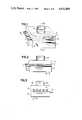
- FIG. 4is a cross section illustrating another embodiment of this invention.
- FIG. 5is a cross section illustrating yet another embodiment of this invention.
- FIG. 6is a cross section taken through FIG. 5 along the line VI--VI
- FIG. 7is a cross section illustrating a further embodiment of this invention.
- FIG. 8is a cross section taken through FIG. 7 along the line VIII--VIII,
- FIG. 9is a cross section illustrating a typical shape of the layer of a hydrophilic and gas-pervious material to be used in the present invention.
- FIG. 10Ais a schematic diagram illustrating a position of measurement in the system of the present invention.
- FIG. 10Bis a cross section taken through FIG. 10A along the line XA--XA, and
- FIG. 11is a graph showing a relation between O 2 pressure and O 2 ( 1 ⁇ )/O 2 of this invention.
- a mixture of an alkaline aqueous solutionsuch as, for example, the aqueous solution of a hydroxide of alkali metal such as sodium hydroxide, potassium hydroxide, or lithium hydroxide or a hydroxide of alkaline earth metal such as calcium hydroxide or magnesium hydroxide with a high-concentration aqueous solution of hydrogen peroxide is caused to wet the surface portion of a layer of a hydrophilic and gas-pervious material possessing fine pores and, at the same time, a molecular chlorine-containing gas is caused to penetrate the layer from the side opposite the surface thereof.
- an alkaline aqueous solutionsuch as, for example, the aqueous solution of a hydroxide of alkali metal such as sodium hydroxide, potassium hydroxide, or lithium hydroxide or a hydroxide of alkaline earth metal such as calcium hydroxide or magnesium hydroxide
- a high-concentration aqueous solution of hydrogen peroxideis caused to wet the surface portion of a
- the mixed aqueous solution wetted in the surface portion of the layer of the materialcontacts and reacts with chlorine while the gas is penetrating the material and the excited molecular oxygen O 2 ( 1 ⁇ ), consequently produced is issued through the surface portion of the layer wetted by the aqueous solution.
- the gaspenetrates the layer and the chlorine of the gas contacts and reacts with the aqueous solution and the excited molecular oxygen, O 2 ( 1 ⁇ ), is generated on the side of the surface portion wetted by the aqueous solution.
- This reaction of the aqueous solution with the chlorineoccurs in an extremely thin layer on the surface of the layer of the material.
- the excited molecular oxygen, O 2 ( 1 ⁇ )so generated immediately departs from the surface of the aqueous solution and moves into an another empty space in which the gas flows. The probability that the excited molecular oxygen once generated is quenched by collision with other molecules in the aqueous solution is extremely small.
- the alkaline aqueous solutionis desired to be an aqueous solution of an alkali metal hydroxide, particularly an aqueous solution of potassium hydroxide or sodium hydroxide.
- the pH of the mixed aqueous solutiongenerally falls in the range of 7.5 to 14, preferably 8 to 11.
- the concentration of hydrogen peroxide in the mixed aqueous solutiongenerally falls in the range of 30 to 90% by weight, preferably 50 to 80% by weight.
- porous ceramicsporous glass, porous metal, and porous organic materials, (such as hydrophilic treated polypropylene, polyvinyl chloride and fluorine resin).
- the pores in the materialhave an average diameter generally in the range of 1 to 20 ⁇ m, preferably 3 to 7 ⁇ m.
- Porosityis 20 to 85%, preferably 35 to 85%, because when the porosity is less than 20%, permeability is too low, and when the porosity is more than 85%, it is difficult to maintain the strength, although it is desirable that the porosity is as high as possible.
- cumulative pore volumeis at least 90% of length of two fold length of the mean diameter and at most 10% of length of half length of the mean diameter, preferably at least 95% and at most 5% respectively.
- This materialmay be in any desired shape. Examples of shapes assumed by the material include a film, a sheet, and a cylindrical body such as a hollow pipe and a hollow fiber. The thickness of the layer of this material generally falls in the range of 0.01 to 20 mm, preferably 0.1 to 5 mm.
- the molecular chlorine-containing gasmay be pure chlorine gas or a mixture of chlorine gas with an inert gas (such as, for example, nitrogen, helium, or argon).
- the amount of the molecular chlorine-containing gas to be suppliedgenerally falls in the range of 1 to 100 mmol/cm 2 .min, preferably 2 to 20 mmol/cm 2 .min as Cl 2 .
- the concentration of chloride gas in the aforementioned mixtureis not less than 5% by volume, preferably 100% by volume.
- the atmosphere on the side of generation of the excited molecular oxygenis kept under low pressure generally in the range of 0.1 to 100 Torr, preferably 0.3 to 10 Torr.
- At least one hollow pipe 16is disposed continuously to the liquid surface of an aqueous solution layer 14 formed by feeding a mixed aqueous solution of an alkaline aqueous solution with an aqueous hydrogen peroxide solution through a mixed aqueous solution inlet 12 into the lower part of a reaction vessel 10 and an empty space 18 overlying the aqueous solution layer 14 is provided with an oxygen gas outlet 20 connected to a pipe (not shown).
- a mixed solution outlet 26is provided when necessary for the purpose of maintaining the concentration of the aqueous solution constant.
- the hollow pipe 16 to be used in the apparatusis a ceramic pipe possessing fine pores of an average diameter of 5 ⁇ m.
- the mixed aqueous solution in the reaction vessel 10is allowed to maintain its concentration constant by feeding the mixed aqueous solution of an alkaline aqueous solution with an aqueous hydrogen peroxide solution through the inlet 12 and discharging it through outlet 20.
- the aqueous hydrogen peroxide solutionis desired to have as high a concentration as possible.
- the concentrationgenerally falls in the range of 70 to 90% by weight, preferably about 90% by weight.
- the voluminal ratio of the aqueous hydrogen peroxide solution to the alkaline aqueous solutionis about 5:1. In the mixed aqueous solution, therefore, the concentration of the hydrogen peroxide is 32 to 82% by weight and that of the alkali is 3 to 25% by weight.
- the component aqueous solutionmay be fed separately to the reaction vessel 10, they are desired to be fed in the form of a homogeneous mixed aqueous solution to the reaction vessel.
- the reaction vessel 10is desired to be evacuated with a vacuum pump to a pressure under not more than 10 mTorr in advance of the admission of the mixed aqueous solution.
- the amount of the mixed aqueous solution to be fed to the reaction vesselis such that the pipe 16 sinks to a depth in the range of 0.5 to 4 mm, preferably 1 to 2 mm below the liquid surface of the mixed aqueous solution.
- the mixed aqueous solutionby the phenomena capillary, wets the entire surface portion of the pipe 16 from the lowermost part of the pipe 16 which is held in contact with the mixed aqueous solution.
- the molecular chlorine-containing gas fed in through the gas inlet 22is caused by the difference of pressure inside and outside the pipe to pass through the fine pores in the pipe and reach the surface portion of the pipe, there to contact and react with the mixed aqueous solution and generate an excited molecular oxygen, O 2 ( 1 ⁇ ).
- the excited molecular oxygen so generatedis discharged from the system through the oxygen gas outlet 20.
- the flow volume of the molecular chlorine-containing gas as Cl 2generally falls in the range of 1 to 100 mmol/cm 2 .min, preferably about 5 mmol/cm 2 .min, based on the unit outer circumferential area of the ceramic pipe.
- FIG. 4illustrates another embodiment of this invention.
- a reaction vessel 30is provided in the intermediate portion thereof with a gas feed chamber 46 and a gas discharge chamber 40 opposed to the gas feed chamber 46.
- a thin sheet of thin membrane 36made of a hydrophilic and gas-pervious material is attached vertically or diagonally.
- a mixed aqueous solution 34 of an aqueous hydrogen peroxide solution with an alkaline aqueous solutionis stored above the two chambers 46, 40 and is allowed to fall in drops onto the chambers, the thin sheet or thin membrane of the material is wetted with the mixed aqueous solution.
- the gas discharge chamber 40 and the reaction chamber 30are evacuated in advance to a stated pressure and then the gas feed chamber 46 is supplied with the molecular chlorine-containing gas.
- the chlorine gaspenetrates the thin sheet or thin membrane 36, comes into contact and reacts with the mixed aqueous solution to induce generation of an excited molecular oxygen, O 2 ( 1 ⁇ ).
- the excited molecular oxygen so generatedis discharged from the system through a gas discharge chamber 40.
- the mixed aqueous solution which has flowed down the thin sheet or thin membranecollects in the lower part of the reaction vessel 30 to form a liquid layer 44.
- the liquid layer 44may be withdrawn from the system when necessary.
- FIG. 5 and FIG. 6illustrate yet another embodiment of this invention which is based on the same principle as the embodiment of FIG. 4.
- a reaction vessel 50is provided in the intermediate portion thereof with a cylindrical gas feed chamber 56 made of a hydrophilic and gas-pervious material which is disposed approximately horizontally and further provided above the gas feed chamber with a mixed aqueous solution feed device 68.
- the reaction vessel 50is evacuated in advance to a stated pressure and then the mixed aqueous solution is allowed to fall in drops from dropping orifices or at least one slit in the lower part of the mixed aqueous solution feed device 68. As the result, the mixed aqueous solution flows down the surface of the cylindrical gas feed chamber 56 while wetting the surface portion of the chamber 56.
- the reaction vessel 50is evacuated in advance to a stated pressure and then the molecular chlorine-containing gas is supplied through a gas inlet 62, the chlorine gas by the difference of pressure is caused to find its way from the gas feed chamber 56 to the interior of the reaction vessel 50.
- the chlorine gascomes into contact and reacts with the aforementioned mixed aqueous solution to induce generation of an excited molecular oxygen, O 2 ( 1 ⁇ ).
- the excited molecular oxygen so generatedis withdrawn from the system through the gas outlet 60.
- the mixed aqueous solution which has flowed down the surface of the cylindrical gas feed chamber 56collects in the lower part of the reaction vessel 50 to form a liquid layer 64.
- the liquid layermay be discharged from the system when necessary. If necessary, the cylindrical gas feed chamber may be rotated.
- FIG. 7 and FIG. 8illustrate still snother embodiment of the present invention.
- a cylindrical gas feed chamber 76made of a hydrophilic and gas-pervious material and disposed inside a reaction vessel 70 is provided around the central axis thereof with rotary shafts 84a, and 84b, so as to be rotatably supported by bearings 86a, and 86b respectively.
- the cylindrical gas feed chamber 76has the lower part thereof immersed in a mixed aqueous solution 74. When this chamber 76 is located about its axis, therefore, the external surface thereof is wholly wetted with the solution.
- the reaction vessel 70When the reaction vessel 70 is evacuated to a stated pressure and the molecular chlorine-containing gas is supplied through a gas inlet 82, the chlorine gas penetrates the layer of the aforementioned material and comes into contact and reacts with the mixed aqueous solution to induce generation of an excited molecular oxygen, O 2 ( 1 ⁇ ).
- the excited molecular oxygen so generatedis withdrawn from the system throug a gas outlet 80.
- the mixed aqueous solutionis allowed to maintain the concentration thereof constant because the solution is fed in through the inlet 72 and discharged through the outlet 88.
- FIG. 9is a cross section illustrating a typical cylindrical gas feed chamber made of a hydrophilic and gas-pervious material used in the present invention.
- a cylindrical ceramic pipe containing pores of an average diameter of 4 to 5 ⁇ m and having an outside diameter of 10 mm, a length of 230 mm, and a wall thickness of 1 mmwas used as a gas feed chamber 16.
- a mixture pH about 10 to 500 ml of an aqueous hydrogen peroxide solution having a hydrogen peroxide concentration of 70% by weight and 500 ml of an aqueous sodium hydroxide solution having a sodium hydroxide concentration of 43% by weightwas supplied. Then, the reaction vessel was evacuated to 5 mTorr and chlorine gas was fed into the gas feed chamber 16. The results are shown in Table 1.
- the absolute amount of O 2 ( 1 ⁇ )was measured with a PbS detector and the amount of unreacted chlorine was measured with a gas analyzer at a point separated by a distance, B, of 600 mm from the outlet of a pipe 600 mm in length after the pipe was cooled with a mixture of dry ice with alcohol to 195 K. at a point separated by a distance, A, of about 500 mm from the cylindrical gas feed chamber 16.
- the formed gaswas suctioned at a rate of 3,000 liters/min. and was cooled with liquified nitrogen at 77 K. for removal of unused chlorine (FIG. 10A).
- FIG. 10A and FIG. 10BAn experiment was carried out with an apparatus illustrated in FIG. 10A and FIG. 10B.
- a reaction vessel 110a cylindrical ceramic pipe containing pores of an average diameter of 4 to 5 ⁇ m and having an outside diameter of 10 mm, a length of 230 mm, and a wall thickness of 1 mm was used as a gas feed chamber 116.
- a liquid dropping tube 114(provided with orifices 0.3 mm in diameter spaced at intervals of 5 mm) connected to a mixing chamber 112 furnished with an aqueous hydrogen peroxide solution inlet 112a and an alkaline aqueous solution inlet 112b was disposed on the aforementioned gas feed chamber 116.
- the reactionwas caused by feeding chlorine gas through a gas inlet 122 and introducing dropwise the same mixed aqueous solution as used in Example 1 at a rate of 1 to 10 ml/sec. from the liquid dropping tube.
- the aqueous solution after the reactionwas discharged through a liquid outlet 126.
- An excited molecular oxygen, O 2 ( 1 ⁇ )was generated on the outer surface portion of a cylindrical gas feed chamber 116.
- the absolute amount of O 2 ( 1 ⁇ )was measured with a PbS detector 132 and the amount of unreacted chlorine was measured with a gas analyzer at a point separated by a distance, B, of 600 mm from the outlet of a pipe 600 mm in length after the pipe was cooled with a mixture of dry ice with alcohol to 195 K. for removal of water at a point separated by a distance, A, of about 500 mm from the cylindrical gas feed chamber 116.
- the formed gaswas suctioned at a rate of 300 liters/min and was cooled with liquified nitrogen at 77 K. in a cooler 134 for removal of unused chlorine.
- Table 1The results were as shown in Table 1.
- a glass filter having 100 ⁇ m of average pore diameter, 10 mm of thickness and 12 cm of diameterwas arranged in a vertically cylindrical reaction vessel at a lower portion thereof and the same mixed aqueous solution as Example 1 was fed into a space surrounded by the vessel and the upper surface of the glass filter. Then chlorine gas was fed into a space surrounded by the vessel and the lower surface of the glass filter so as to penetrate the glass filter under a similar condition of Example 5. Yields of O 2 ( 1 ⁇ )/O 2 and O 2 /Cl 2 were measured by the same method as Example 5. The results were as shown in Table 1.
Landscapes
- Chemical & Material Sciences (AREA)
- Organic Chemistry (AREA)
- Inorganic Chemistry (AREA)
- Lasers (AREA)
Abstract
Description
H.sub.2 O.sub.2 +2NaOH+Cl.sub.2 O.sub.2 (.sup.1 Δ)+2NaCl+2H.sub.2 O
TABLE 1 ______________________________________ Feed rate of Pres- chlorine sure of Pressure Yield Yield mmol/ oxygen of O.sub.2 (.sup.1 Δ) O.sub.2 (.sup.1 Δ)/ O.sub.2 /Cl.sub.2 Example cm.sup.2 -min mTorr mTorr O.sub.2 % % ______________________________________ 1 0.97 683 512 75 80 2 1.57 773 549 71 73 3 2.21 840 563 67 62 4 2.88 902 568 63 51 5 1.10 751 511 68 99 6 2.08 1410 756 54 98 7 3.17 2119 918 43 91 8 5.74 2723 882 32 68 9 9.92 3853 894 23 60 10 15.82 5020 803 16 52 Control 1 0.57 606 261 43 99 2 0.86 920 377 41 97 3 1.25 1327 504 38 94 4 1.58 1654 546 33 91 ______________________________________
Claims (18)
Priority Applications (1)
| Application Number | Priority Date | Filing Date | Title |
|---|---|---|---|
| US06/846,254US4643889A (en) | 1986-03-31 | 1986-03-31 | System for generation of singlet-delta oxygen |
Applications Claiming Priority (1)
| Application Number | Priority Date | Filing Date | Title |
|---|---|---|---|
| US06/846,254US4643889A (en) | 1986-03-31 | 1986-03-31 | System for generation of singlet-delta oxygen |
Publications (1)
| Publication Number | Publication Date |
|---|---|
| US4643889Atrue US4643889A (en) | 1987-02-17 |
Family
ID=25297376
Family Applications (1)
| Application Number | Title | Priority Date | Filing Date |
|---|---|---|---|
| US06/846,254Expired - Fee RelatedUS4643889A (en) | 1986-03-31 | 1986-03-31 | System for generation of singlet-delta oxygen |
Country Status (1)
| Country | Link |
|---|---|
| US (1) | US4643889A (en) |
Cited By (14)
| Publication number | Priority date | Publication date | Assignee | Title |
|---|---|---|---|---|
| US5229100A (en)* | 1988-06-13 | 1993-07-20 | The United States Of America As Represented By The Secretary Of The Air Force | Rotating disk singlet oxygen generator |
| US5378449A (en)* | 1993-08-31 | 1995-01-03 | The United States Of America As Represented By The Secretary Of The Air Force | Formation of basic hydrogen peroxide |
| US5417928A (en)* | 1994-02-25 | 1995-05-23 | Rockwell International Corporation | Singlet delta oxygen generator and process |
| DE4442463A1 (en)* | 1994-11-29 | 1996-05-30 | Deutsche Forsch Luft Raumfahrt | Generator and method for producing a product gas |
| US5624654A (en)* | 1996-05-13 | 1997-04-29 | Trw Inc. | Gas generating system for chemical lasers |
| EP0819647A3 (en)* | 1996-07-15 | 1998-07-29 | Boeing North American, Inc. | Salt free lithium hydroxide base for chemical oxygen iodine lasers |
| US5883916A (en)* | 1997-07-09 | 1999-03-16 | Trw Inc. | Integrated valve and flow control apparatus and method for chemical laser system |
| US5900219A (en)* | 1994-11-29 | 1999-05-04 | Deutsche Forschungsanstalt Fuer Luft -Ung Raumfahrt E.V. | Generator and process for generating a product gas |
| US5974072A (en)* | 1997-07-09 | 1999-10-26 | Trw Inc. | High energy airborne coil laser |
| US20020098246A1 (en)* | 2001-01-22 | 2002-07-25 | Howes Randolph M. | Compositions, methods, apparatuses, and systems for singlet oxygen delivery |
| US20030227955A1 (en)* | 2002-06-10 | 2003-12-11 | George Emanuel | Efficient method and apparatus for generating singlet delta oxygen at an elevated pressure |
| US20040234450A1 (en)* | 2001-01-22 | 2004-11-25 | Howes Randolph M. | Compositions, methods, apparatuses, and systems for singlet oxygen delivery |
| US20060251572A1 (en)* | 2004-10-20 | 2006-11-09 | Schroeder Brady M | Membrane singlet delta oxygen generator and process |
| US20070110117A1 (en)* | 2002-06-10 | 2007-05-17 | George Emanuel | Efficient Method and Apparatus for Generating Singlet Delta Oxygen at an Elevated Pressure |
Citations (6)
| Publication number | Priority date | Publication date | Assignee | Title |
|---|---|---|---|---|
| US4246252A (en)* | 1979-04-13 | 1981-01-20 | The United States Of America As Represented By The Secretary Of The Air Force | Gas generating system for chemical lasers |
| US4310502A (en)* | 1980-05-29 | 1982-01-12 | Rockwell International Corporation | Singlet delta oxygen generator and process |
| US4318895A (en)* | 1979-11-05 | 1982-03-09 | Mcdonnell Douglas Corporation | Process for generating singlet-oxygen |
| US4342116A (en)* | 1980-03-11 | 1982-07-27 | The Garrett Corporation | Dry excited singlet delta oxygen generator |
| US4461756A (en)* | 1982-09-30 | 1984-07-24 | The United States Of America As Represented By The Secretary Of The Air Force | Singlet delta oxygen generator |
| US4558451A (en)* | 1982-07-19 | 1985-12-10 | The United States Of America As Represented By The Secretary Of The Air Force | Tubular singlet delta oxygen generator |
- 1986
- 1986-03-31USUS06/846,254patent/US4643889A/ennot_activeExpired - Fee Related
Patent Citations (6)
| Publication number | Priority date | Publication date | Assignee | Title |
|---|---|---|---|---|
| US4246252A (en)* | 1979-04-13 | 1981-01-20 | The United States Of America As Represented By The Secretary Of The Air Force | Gas generating system for chemical lasers |
| US4318895A (en)* | 1979-11-05 | 1982-03-09 | Mcdonnell Douglas Corporation | Process for generating singlet-oxygen |
| US4342116A (en)* | 1980-03-11 | 1982-07-27 | The Garrett Corporation | Dry excited singlet delta oxygen generator |
| US4310502A (en)* | 1980-05-29 | 1982-01-12 | Rockwell International Corporation | Singlet delta oxygen generator and process |
| US4558451A (en)* | 1982-07-19 | 1985-12-10 | The United States Of America As Represented By The Secretary Of The Air Force | Tubular singlet delta oxygen generator |
| US4461756A (en)* | 1982-09-30 | 1984-07-24 | The United States Of America As Represented By The Secretary Of The Air Force | Singlet delta oxygen generator |
Non-Patent Citations (6)
| Title |
|---|
| Bachar, J., et al., Appl. Phys. Lett. 41(1), Jul. 1, 1982, pp. 16 18.* |
| Bachar, J., et al., Appl. Phys. Lett. 41(1), Jul. 1, 1982, pp. 16-18. |
| Bonnet, J., et al., Appl. Phys. Lett. 45(10), Nov. 15, 1984, pp. 1009 1011.* |
| Bonnet, J., et al., Appl. Phys. Lett. 45(10), Nov. 15, 1984, pp. 1009-1011. |
| Richardson, R. J., et al., J. Appl. Phys. 52(8), Aug. 1981, pp. 4962 4969.* |
| Richardson, R. J., et al., J. Appl. Phys. 52(8), Aug. 1981, pp. 4962-4969. |
Cited By (21)
| Publication number | Priority date | Publication date | Assignee | Title |
|---|---|---|---|---|
| US5229100A (en)* | 1988-06-13 | 1993-07-20 | The United States Of America As Represented By The Secretary Of The Air Force | Rotating disk singlet oxygen generator |
| US5378449A (en)* | 1993-08-31 | 1995-01-03 | The United States Of America As Represented By The Secretary Of The Air Force | Formation of basic hydrogen peroxide |
| US5417928A (en)* | 1994-02-25 | 1995-05-23 | Rockwell International Corporation | Singlet delta oxygen generator and process |
| DE4442463A1 (en)* | 1994-11-29 | 1996-05-30 | Deutsche Forsch Luft Raumfahrt | Generator and method for producing a product gas |
| US5900219A (en)* | 1994-11-29 | 1999-05-04 | Deutsche Forschungsanstalt Fuer Luft -Ung Raumfahrt E.V. | Generator and process for generating a product gas |
| US5624654A (en)* | 1996-05-13 | 1997-04-29 | Trw Inc. | Gas generating system for chemical lasers |
| US5859863A (en)* | 1996-05-13 | 1999-01-12 | Trw Inc. | Gas generating system for chemical lasers |
| US5925286A (en)* | 1996-05-13 | 1999-07-20 | Trw Inc. | Gas generating system for chemical lasers |
| EP0819647A3 (en)* | 1996-07-15 | 1998-07-29 | Boeing North American, Inc. | Salt free lithium hydroxide base for chemical oxygen iodine lasers |
| US6010640A (en)* | 1996-07-15 | 2000-01-04 | Boeing North American, Inc. | Salt free lithium hydroxide base for chemical oxygen iodine lasers |
| US5974072A (en)* | 1997-07-09 | 1999-10-26 | Trw Inc. | High energy airborne coil laser |
| US5883916A (en)* | 1997-07-09 | 1999-03-16 | Trw Inc. | Integrated valve and flow control apparatus and method for chemical laser system |
| US20020098246A1 (en)* | 2001-01-22 | 2002-07-25 | Howes Randolph M. | Compositions, methods, apparatuses, and systems for singlet oxygen delivery |
| US20040234450A1 (en)* | 2001-01-22 | 2004-11-25 | Howes Randolph M. | Compositions, methods, apparatuses, and systems for singlet oxygen delivery |
| US20050186135A1 (en)* | 2001-01-22 | 2005-08-25 | Howes Randolph M. | Compositions, methods, apparatuses, and systems for singlet oxygen delivery |
| US20030227955A1 (en)* | 2002-06-10 | 2003-12-11 | George Emanuel | Efficient method and apparatus for generating singlet delta oxygen at an elevated pressure |
| US7116696B2 (en)* | 2002-06-10 | 2006-10-03 | Ksy Corporation | Efficient method and apparatus for generating singlet delta oxygen at an elevated pressure |
| US20070110117A1 (en)* | 2002-06-10 | 2007-05-17 | George Emanuel | Efficient Method and Apparatus for Generating Singlet Delta Oxygen at an Elevated Pressure |
| US7397836B2 (en) | 2002-06-10 | 2008-07-08 | Ksy Corporation | Efficient method and apparatus for generating singlet delta oxygen at an elevated pressure |
| US20060251572A1 (en)* | 2004-10-20 | 2006-11-09 | Schroeder Brady M | Membrane singlet delta oxygen generator and process |
| US7242706B2 (en)* | 2004-10-20 | 2007-07-10 | The Boeing Company | Membrane singlet delta oxygen generator and process |
Similar Documents
| Publication | Publication Date | Title |
|---|---|---|
| US4643889A (en) | System for generation of singlet-delta oxygen | |
| JP3213430B2 (en) | Gas separator and method for producing the same | |
| KR900005691B1 (en) | Method and apparatus for rapid carbonation | |
| KR100485490B1 (en) | Apparatus for generating fluorine gas | |
| JP4996925B2 (en) | Apparatus and method for osmotic membrane distillation | |
| US5910238A (en) | Microspheres for combined oxygen separation, storage and delivery | |
| KR940001383B1 (en) | Method of liquefying and condensing nitrogen trifluoride and a method of purifying nitrogen trifluoride | |
| US4564373A (en) | Method for bubble-free gas feed | |
| Spencer et al. | CCCLIV.—Chemical kinetics of the system Ag 2 CO 3⇌ Ag 2 O+ CO 2 | |
| US5114549A (en) | Method and apparatus for treating water using electrolytic ozone | |
| FI79824B (en) | FOERFARANDE FOER FRAMSTAELLNING AV KLORDIOXID MEDELST FOERAONGNING GENOM EN MEMBRAN. | |
| US5425857A (en) | Process and device for the electrolytic generation of arsine | |
| Yang et al. | Effect of membrane preparation on the lifetime of supported liquid membranes | |
| AU615769B2 (en) | Electrochemical cell having dual purpose electrode | |
| JP4151088B2 (en) | Hydrogen-containing ultrapure water supply device | |
| CA2435156A1 (en) | Method and apparatus for production of droplets | |
| US4545964A (en) | Process for the preparation of porous products based on cobalt fluoride or lead fluoride | |
| JPH0699123B2 (en) | Excited Oxygen Molecule O ▲ Lower 2 ▼ (Upper 1 ▼ Δ) Generation Method | |
| JP3221499B2 (en) | Water filtration method | |
| US3734802A (en) | Apparatus for leaching glass films | |
| US5599518A (en) | Catalytic process for chlorine dioxide generation from chloric acid | |
| EP0241577A1 (en) | Method for separating and concentrating an organic component having a low-boiling point from an aqueous solution | |
| US5318706A (en) | Method of supplying dilute hydrofluoric acid and apparatus for use in this method for supplying the acid | |
| JP2000317210A (en) | Chemical solution degassing apparatus and chemical solution degassing method | |
| JP4438077B2 (en) | Method for preparing gas-dissolved water for cleaning electronic materials |
Legal Events
| Date | Code | Title | Description |
|---|---|---|---|
| AS | Assignment | Owner name:MITSUI GRINDING WHEEL CO., LTD., 11-10, OAZA-SYAMA Free format text:ASSIGNMENT OF ASSIGNORS INTEREST.;ASSIGNORS:UCHIYAMA, TARO;TAKEHISA, KIWAMU;ISHIZAKI, ISAO;REEL/FRAME:004548/0193 Effective date:19860325 Owner name:UCHIYAMA, TARO, 2663-9, NARUSE, MACHIDA-SHI, TOKYO Free format text:ASSIGNMENT OF ASSIGNORS INTEREST.;ASSIGNORS:UCHIYAMA, TARO;TAKEHISA, KIWAMU;ISHIZAKI, ISAO;REEL/FRAME:004548/0193 Effective date:19860325 Owner name:MITSUI GRINDING WHEEL CO., LTD., JAPAN Free format text:ASSIGNMENT OF ASSIGNORS INTEREST;ASSIGNORS:UCHIYAMA, TARO;TAKEHISA, KIWAMU;ISHIZAKI, ISAO;REEL/FRAME:004548/0193 Effective date:19860325 Owner name:UCHIYAMA, TARO,, JAPAN Free format text:ASSIGNMENT OF ASSIGNORS INTEREST;ASSIGNORS:UCHIYAMA, TARO;TAKEHISA, KIWAMU;ISHIZAKI, ISAO;REEL/FRAME:004548/0193 Effective date:19860325 | |
| CC | Certificate of correction | ||
| FPAY | Fee payment | Year of fee payment:4 | |
| REMI | Maintenance fee reminder mailed | ||
| LAPS | Lapse for failure to pay maintenance fees | ||
| FP | Lapsed due to failure to pay maintenance fee | Effective date:19950222 | |
| STCH | Information on status: patent discontinuation | Free format text:PATENT EXPIRED DUE TO NONPAYMENT OF MAINTENANCE FEES UNDER 37 CFR 1.362 |